atlas ptc700cdn.gregsmithequipment.com/documents/manuals/tirechangers/ptc… · 4 1.0 introduction...
TRANSCRIPT

Ed.11/18 Cod. 3044302
PTC700
Use and maintenance instruction manual
EnglishOriginal Instructions
ATLAS PTC700

2

3
CONTENTS
1.0 INTRODUCTION.................................................................................................................................................4 1.1_Tyre-Changer data...................................................................................................................................4 1.2_Manufacturer data.............................................................................................................................4 1.3_Data plate....................................................................................................................................42.0 GENERAL DESCRIPTION.....................................................................................................................................43.0 SPECIFICATIONS.....................................................................................................................................54.0 WARNING LABEL PLACEMENT............................................................................................................................65.0 GENERAL SAFETY RULES.................................................................................................................................76.0 SAFETY DEVICES....................................................................................................................................77.0 TRANSPORT......................................................................................................................................................88.0 UNPACKING......................................................................................................................................................89.0 INSTALLATION................................................................................................................................................9 9.1_Space required for positioning...........................................................................................................9 9.2_Tyre-Changer placement and connections..............................................................................................9 9.3_Installation and assembly.................................................................................................................10 9.4_Connection to the electrical network..............................................................................................11 9.5_Connection to the compressed air network....................................................................................11 9.6_Laser pointers calibration...............................................................................................................1110.0 EQUIPMENT COMPONENTS.................................................................................................................1211.0 CONTROLS DESCRIPTION AND FUNCTION CONTROL..................................................................................1312.0 RIM AND TYRE IDENTIFICATION.......................................................................................................1413.0 VALVE POSITION......................................................................................................................................1414.0 WHEELS AND TYRES CLASSIFICATION...................................................................................................15 14.1_Standard wheels............................................................................................................................15 14.2_Low-profiled tyre (UHP)wheels...........................................................................................15 14.3_RUN-FLAT tyrewheels.......................................................................................................1515.0 WDK RULES...................................................................................................................................................1516.0 WHEEL POSITIONING AND CENTERING ONTO CLAMPING CHUCK........................................................1617.0 WHEEL CLAMPING OPERATION WITH SMART LOCK.................................................................................16 17.1_Tightening adjustment............................................................................................................17 17.2_Maintenance................................................................................................................................1818.0 SWITCHING ON/OFF........................................................................................................................................18 18.1_Machine start up...........................................................................................................................18 18.2_Switchingoffthemachine(anemergencystop)...........................................................................1819.0 RIM SETTING - STEP 1 - ...................................................................................................................1820.0 TYRE PRESSURE MONITORING SYSTEM (TPMS) ......................................................................................1921.0 BEAD BREAKING - STEP 2- ............................................................................................................................20 21.1_Upperbeadbreaking..........................................................................................................................20 21.2_Lower bead breaking.....................................................................................................................2122.0 MATCH-MOUNTING.........................................................................................................................................2123.0 TYRE DEMOUNTING - STEP 3 - .............................................................................................................................22 23.1_Upper bead demounting.........................................................................................................22 23.2_Lower bead demounting........................................................................................................23 23.3_UHPandRUN-FLAT tyresdemounting.....................................................................................2324.0 TYRE MOUNTING - STEP 4 - .................................................................................................................................24 24.1_Lower bead mounting.................................................................................................................24 24.2_Upper beadmounting.................................................................................................................25 24.3_UHPandRUN-FLATtyresmounting..............................................................................................2625.0 INFLATION...................................................................................................................................................27 25.1_Tubeless tyre inflation (optional)..............................................................................................2826.0 STANDARD ACCESSORIES..............................................................................................................................2927.0 OPTIONAL ACCESSORIES.........................................................................................................................3128.0 REPOSITIONING......................................................................................................................................3329.0 STORAGE......................................................................................................................................3330.0 SCRAPPING AND DISPOSAL.............................................................................................................................3331.0 OIL TREATMENT.................................................................................................................................3332.0 MAINTENANCE.................................................................................................................................................34 32.1_Standard maintenance................................................................................................................34 32.2_Laser pointers calibration.............................................................................................................35
32.2.1_Rimdiameterlaserpointercalibration(verticallaserpointer)......................................35 32.2.2_Rimwidthlaserpointercalibration(horizontallaserpointer)......................................38 32.3_Extraordinary maintenance.........................................................................................................4033.0 TROUBLESHOOTING CHART...................................................................................................................4134.0 WIRING DIAGRAM........................................................................................................................4435.0 CLAMPING CHUCK MOTOR WIRING DIAGRAM......................................................................................4636.0 CLAMPING CHUCK CARRIAGE AND TOOLS CARRIAGE MOVEMENT DIAGRAM....................................4737.0 PNEUMATIC DIAGRAMS...................................................................................................4848.0 SERVICE REPORTS......................................................................................................................51
CHAPTER Page

4
1.0 INTRODUCTION
Thanks for choosing this tyre changer.Thissuperautomatictouchlessleverlesstyrechangerisdesignedfortopprofessionaltyrespecialists,servicingrunflatandUHPtyreswithnotool/rimcontact.Inordertoensurecorrect,efficientandsafeoperation,andtoprolongtheworklifeofthemachine,pleasereadthismanual carefully and follow the instructions.
1.1 Tyre-Changer data:
Please refer to “Tyre-Changer Model” and “Serial Number” data on the Data-Plate to provide our Technical Service Dept. with the necessary details for prompt assistance and spare-parts tracking.Thesedataarefoundonadhesivelabelsappliedonthemachine.Forclarityandconvenience,wehaveinsertedFAC-SIMILEintheboxbelow.
1.2 Manufacturer data:
Pleasecheckthe“DeclarationsofConformity”atpage2ofthisManualandTyre-ChangerData-Plate.
1.3 Data plate:
This manual is an integral part of the product.Before using the tyre changer, read carefully the warnings and instructions contained in this manual since theyprovideimportantinformationonoperatingsafetyandmaintenance.
Keep this Manual in good conditions for further references.
NOTE: Some parts or components of standard production may differ from the illustrations contained in this manual.
2.0 GENERAL DESCRIPTION
Thetyrechangerisdesignedtodemountandmounttyresofcarsandlightcommercialvehicleswithrimsfrom12”to28”andmaximumdiameterof1200(47”)mm.
Thetyrechangerisdesignedtodemountandmountconventionaltyresofpassengercars,lightcommercialvehicles,nextgeneration“self-supporting”RUN-FLATtyresandlowprofiletyres(UHP)onsteeland/oralloyrims,evenbig-sizetyres.
TheTyre-ChangerisNOTintendedfordemountingcompletely-orpartially-inflatedtyres,dirtytyres,norforrim bendingorfordemountingindustrialwheelswithsplitringrims.AlltheseoperationsareFORBIDDEN.

5
Connections:-Powersupply:230V-1Ph-50/60HzFormoredetailedinformation,see chapter 9.4,“Connection to the electric network”onpage11.-Operatingpressure:8÷10bar(116÷145psi)-Supplypressure:8÷14bar(116÷203psi)-Air-feedingpressureregulatorsetat10bar(145psi)standardincluded-Inflatingair-pressureregulatorsetat3,5bar(50psi)standardincluded
Working capacity:-Rimclampingrange:12”to28”-Maximumrimwidth:16”(406mm)-Max.tyrediameter:47”(1200mm)
Motoinverter clamping chuck details:-Motorspower:0,75kW-2speed-Maximumtorque:1200Nm-Clockwiserotationspeed:7÷16rpm-Workingnoiselevel:<70dB
Bead-Breaking units:-Bead breaker cylindersforceat10Bar:12037N(1227Kg)-Maximumbeadbreakingrange:670mm(26’’)-Bead-pressingtoolcylinderpowerat10Bar:3055N(312kg)
Other Details:-Minimumoveralldimensionsmm:1800x1650x1650H-Netweight(optionalaccessoriesexcluded):561kg-Operatingtemperaturerange:min+5°Cmax+50°C(+41°÷+122°F)-Storagetemperaturerange:-5°÷+60°C(23°÷140°F)
Standard accessories (ref. page 29):-Lube paste bucket and brush-Plastictyrelever-Kitofnylonprotectorsformountingtool-PlasticprotectionsforSmartLockcenteringcone-Rubber protections for clamping chuck faceplate-Plasticprotectionsforclampingchuckdrivingpin
Main optional accessories (ref. page 31):-WLWheelLifter(Maxwheelweight80kg)-Wheelclampingadaptorforreversemountedandplasticcladwheels-ConesforclampinglighttruckandLCVswheels-Tubelessinflationexternalkit(Gun)-NylonconesforspecialLamborghini,Porsche,BMWwheels-WDKKit
1860
1140
Dimensions (mm)
1430
1650
1800 1650
3.0 SPECIFICATIONS
-PlasticconeØ70mmforclampingspecialalloyrims-Reducing ring for clamping chuck faceplate-AdjustmentknobforSmartLock-Cleaning brush for clamping chuck and Smart Lock-SpareOringsforSmartLock-Bead pressing clamp-Set of rubber protectors-Airlubricator,airfilter/watertrap-Calibration jig and magnet
Grossweight611Kg.(withoutoptionalaccessories)
Woodenpallet
Carton Box
Packing details (mm)
6
Cod. 3000048
Cod. 3040491R
Cod.3025916
Cod.3042077
Cod. 3041778
Cod.3040492
Cod.3040494
(optional)
Cod. 3005410
Cod. 3044247Cod. 3040487
Cod. 3040489 Cod. 3040486
Cod. 3044238 Cod. 3040490Cod. 3041345
Cod. 3041521C
Cod. 3042080
Cod. 3042078
Cod. 3042079
Cod. 3042081
DIMEN
SION
I / DIMEN
SION
S - Larghezza / W
idth: 30 mm
(± 1mm
)- Lunghezza / Lenght: 340 m
m (± 1 m
m)
MATERIALE: pvc antigraffio trasparente m
attato spessore 0.2 mm
con colla 3M;
Resistente agli agenti atmosferici;
Deformazione am
missibile dipendente dagli agenti atm
osferici ±2%;
COLO
RI:- giallo RAL 1021 / P 116C- nero
MATERIAL: pvc scratch resistant thickness 0.2 m
m w
ith 3M glue;
Weather resistant;
Maxim
um perm
issible deformation due to atm
ospheric condition ±2%;
COLO
RS:- yellow
RAL 1021 / P 116C- black
340 ± 1 mm
30 ± 1 mm
Rev.Data /Date
Descrizione / DescriptionDisegnato /
DrawnControllato /
CheckedApprovato / Approved
Modif. / Mod.
102/12/2015
Disegno rilasciato per produzione / Drawing released for production
S. CaramazzaI. Benedettini
A. MacchiaP97
Kg.0
vedinota/seenote
-
© Sicam
srl. All rights reserved, also regarding any disposal, exploitation, reproduction, editing, distribution as well as in the event of applications for industrial property rights.
ITA/IN
G
F E D C B A
43
21 1
23
45
67
8
D C B A
Disegnato / Drawn
1
HRCProf. / Depth
Rivestimento / Surface
1180
CORREGGIO (RE)
BWN1 / 1
A3
SW
26/10/2015A.M
acchiaData / Date
PVC
Approvato / ApprovedData / Date
Controllato / CheckedData / Date
Size/Gst.Missed details/Fehlende Angaben
Trattamento / Treatment
Mat. / Mat.Da / From
Repl. for
Doc.type
Foglio / Sheet
Ind.DP/TD
Repl. by
Format
MNR
Scala / ScaleConf. Mat. / Mat. meets
Crit. P.
Ling. / Lang.Peso / Weight
Syst.
P.B
artoli15/10/2015
© Sicam
srl. Si riserva a termini di legge la proprietà del presente disegno con divieto di utilizzo, riproduzione, m
odifica, distribuzione senza autorizzazione.
30/10/2015
1695105291
ETIC
HETTA
SICUREZZA
AREALA
VOROLIFT/S
TICKER
10:1
S.C
aramazza
ITA/IN
G
PVC
Kg.0
vedinota/seenote
-
© Sicam
srl. All rights reserved, also regarding any disposal, exploitation, reproduction, editing, distribution as well as in the event of applications for industrial property rights.
ITA/IN
G
F E D C B A
43
21 1
23
45
67
8
D C B A
Disegnato / Drawn
1
HRCProf. / Depth
Rivestimento / Surface
1180
CORREGGIO (RE)
BWN1 / 1
A3
SW
26/10/2015A.M
acchiaS.C
aramazza
Data / DateApprovato / Approved
Data / DateControllato / Checked
Data / DateSize/Gst.
Missed details/Fehlende AngabenTrattamento / Treatment
Mat. / Mat.Da / From
Repl. for
Doc.type
Foglio / Sheet
Ind.DP/TD
Repl. by
Format
MNR
Scala / ScaleConf. Mat. / Mat. meets
Crit. P.
Ling. / Lang.Peso / Weight
Syst.
P.B
artoli22/09/2015
© Sicam
srl. Si riserva a termini di legge la proprietà del presente disegno con divieto di utilizzo, riproduzione, m
odifica, distribuzione senza autorizzazione.
30/10/2015
1695105292
ETIC
HETTE
LEVASOLLE
VATO
RE/S
TICKER
1:2
ITA/IN
G
DIMEN
SION
I / DIMEN
SION
S - Larghezza / W
idth: 14 mm
(± 0,5 mm
)- Lunghezza / Lenght: 475 m
m (± 1 m
m)
MATERIALE: pvc bianco spessore 200 m
icron con colla acrilica permanente;
Resistente agli agenti atmosferici;
Deformazione am
missibile dipendente dagli agenti atm
osferici ±2%;
COLO
RI:- giallo RAL 1021 / P.116C- nero
MATERIAL: pvc w
hite thickness 200 micron w
ith permanent acrylic glue;
Weather resistant;
Maxim
um perm
issible deformation due to atm
ospheric condition ±2%;
COLO
RS:- yellow
RAP 1021 / P.116C- black
475 ± 1 mm
14 mm ± 0,5
Rev.Data /Date
Descrizione / DescriptionDisegnato /
DrawnControllato /
CheckedApprovato / Approved
Modif. / Mod.
102/12/2015
Disegno rilasciato per produzione / Drawing released for production
S. CaramazzaI. Benedettini
A. MacchiaP97
Cod. 3042601
Cod. 3042605(optional)
Cod. 3041958
Cod. 3019232B
Cod. 3042405
1 2 3 4
E E
F F
Il presente disegno è proprietà della Giuliano Group SpA e non può essere riprodotto o ceduto a terzi previa autorizzazione scritta
GREZZO
PESI SEMILAVORATI Kg.
MATERIALE
TRATT. TERMICO
DUREZZA
COD. MAT. GREZZ0
TRATT. SUP.
ISQ 87SEGUIRE LA SEGUENTE ISTRUZIONE:PER LE TOLLERANZE NON INDICATE SUL DISEGNO
p
SALDATURA AD ARCO CONFILO ANIMATO IN
ATMOSFERA DI GAS ATTIVO (80%Ar , 20% CO2)136
135 DI GAS ATTIVO (80%Ar , 20% CO2)
SALDATURA AD ARCO CONFILO IN ATMOSFERA
DESCRIZIONE
da S235
DOMEX 490÷740
a S355
T1
TIPO DI ACCIAIO
C20 ÷ C60
Sm x45°
R=
SMUSSINON QUOTATI
RACCORDINON QUOTATI
TOGLIERE TRUCIOLIE SPIGOLI VIVI
DATA:
UNITA' DI MISURA mm
MACCHINA
DIMENSIONI ISO
DISEGNO MOD.
SCALA: 1:1
N° PEZZI PER MACCHINA
DISEGNATORE
COD.LAV.DENOMINAZIONE
DIMENSIONI DA CONTROLLARE
FINITO
CODICE DI CONDIVISIONE
PROCEDIMENTI DI SALDATURA p (UN IEN 22553)
Dra
w2
1 2 3 4
A A
B B
C C
D D
DECALCO PULIZIA SMART LOCK
E MANDRINO 30 41521
SMTG
14/09/2016
Colognesi
Avery 806 YellowE806
CC
03/10/2017: C) Aggiunta fase di regolazione (Vezzani)10/10/2016: B) Modificata numerazione fasi di pulizia (Vignoli)18/05/2016: A) Modificata grafica adesivo ok Pellicciari
16
981
Cod.3025916
Cod.3025916
Cod. 3035727
Cod. 3042405
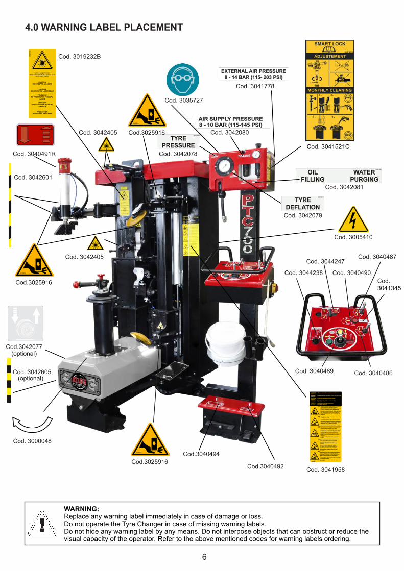
4.0 WARNING LABEL PLACEMENT
WARNING:Replace any warning label immediately in case of damage or loss.Do not operate the Tyre Changer in case of missing warning labels.Do not hide any warning label by any means. Do not interpose objects that can obstruct or reduce the visualcapacityoftheoperator.Refertotheabovementionedcodesforwarninglabelsordering.

7
The Tyre-Changer may only be used by specially trained and authorized expert personnel.
- The use of the machine is forbidden to disabled operators if their disabilities may affect the safety of the workingoperations.-Anytamperingormodificationtotheequipmentwithoutthemanufacturer’sexpresspriorauthorizationwillrelievethemanufacturerfromallresponsibilityfordamagederivingfromorreferabletosuchactions.-RemovingortamperingwithsafetydevicesimmediatelyinvalidatetheguaranteeandrepresentsaviolationofEuropeanSafetyLegislation.-TheTyre-Changerisequippedwithinformativeandwarninglabels,whicharedesignedandproducedtolastintime. If they should deteriorate, user shall request replacement decals.
5.0 GENERAL SAFETY RULESTheTyre-Changeristobeoperatedonlybyqualifiedandauthorisedpersonnel.
Aqualifiedoperatorissomeonewhohasfullyunderstoodtheinstructionsdescribedinthisoperationandmaintenancemanual,hasbeenspecificallytrainedandisawareofsafetystandardsathisworkplace.
Theoperatorsusingthemachineshallnotbeundertheinfluenceofdrugs,alcoholorotherintoxicatingSubstances,asthis may interfere with their ability to work safely.
Forgreatersecurityagainston-the-jobinjuries,theoperatorsshallwearsafetyfootwear,gloves,protectiongogglesandshallNOTwearanyformoflooseclothingthatcouldgetcaughtuporrestricttheoperator’smovements.
The operator must be able to:
- read and understand all instructions in the user and maintenance manual so as to be able to use the machine correctly and safely.- read and understand the danger warnings.- understand the characteristics of the machine.-keepunauthorizedpeopleawayfromtheworkingarea.- make sure that the setting in motion of the machine has been carried out in compliance with all applicable rules andregulations.- make sure all operators are familiar with the machine and know how to use it safely and correctly.-avoidtouchingmovingpartsorpressurisedpartswithoutfirstdisconnectingthemachinefromtheelectricalandairpower supply.-keeptheoperationinstructionmanualwithcareinaneasilyaccessibleplace,sothatitcanbeconsultedwheneverneeded.
INCASEOFFIRE,USEONLYDRYCHEMICHALORCO2EXTINGUISHERSTOPUTTHEFIREOUT
6.0 SAFETY DEVICESThetyrechangerisequippedwithsafetydevicesthataredesignedtoguaranteethesafetyofthemachineoperator:-Mainpowerswitchwithemergencystopfunction:cutsoffpowersuppliedtothemachine.-Pressurelimitingvalve,installedinsidethemachinepreventsthepressurefromexceeding3,5bar(50psi)duringinflation.-Pressureregulatorwithairsupplypressuregaugelimitedtomaximumworkingpressure(10bar(145psi)).OnTyre-Changersequippedwith“Tubelesstyrebeadseatingsystem”:-Maximumpressurevalve,installedontotheairtankpreventsthepressurefromexceeding11bar(160psi).
Removing or tampering with safety devices immediately invalidates the guarantee andrepresents a breach of the European Safety Legislation.
WATERextinguisher
FOAMextinguisher
POWDERextinguisher
CO2extinguisher
DRY materialsFLAMMABLE liquidsELECTRICAL equipment
OK OK OK OKOK OK OK
OK OKNONO NO
8
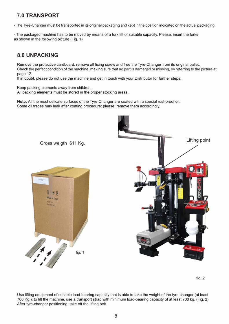
Grossweigth611Kg.
fig.2
fig.1
7.0 TRANSPORT- The Tyre-Changer must be transported in its original packaging and kept in the position indicated on the actual packaging.
-Thepackagedmachinehastobemovedbymeansofaforkliftofsuitablecapacity.Please,inserttheforksasshowninthefollowingpicture(Fig.1).
8.0 UNPACKINGRemovetheprotectivecardboard,removeallfixingscrewandfreetheTyre-Changerfromitsoriginalpallet.Check the perfect condition of the machine, making sure that no part is damaged or missing, by referring to the picture atpage 12.If in doubt, please do not use the machine and get in touch with your Distributor for further steps.
Keeppackingelementsawayfromchildren.Allpackingelementsmustbestoredintheproperstockingareas.
Note: AllthemostdelicatesurfacesoftheTyre-Changerarecoatedwithaspecialrust-proofoil.Someoiltracesmayleakaftercoatingprocedure:please,removethemaccordingly.
Useliftingequipmentofsuitableload-bearingcapacitythatisabletotaketheweightofthetyrechanger(atleast700Kg.);toliftthemachine,useatransportstrapwithminimumload-bearingcapacityofatleast700kg.(Fig.2)Aftertyre-changerpositioning,takeofftheliftingbelt.
Lifting point

9
Fig.1
500
500
500
1900
500
100
500
1900
500
500
500
1900
9.2 Tyre-Changer placement and connectionsPlaceTyre-Changerontoaflat,smoothandnotslipperyfloorwithasuitableloadcapacity.The machine need not necessarily be anchored to the ground, but if you prefer to do so, drill holes 100 mm deep onthe ground in correspondence of holes at the machine rear base by using a 10 mm drill bit of suitable length. Insert suitablemetalanchordowelsintheholesdrilledandsecurefirmly.If the machine is installed outside it must be protected by a appropriate lean-to shed.The installation site should be equipped with an electrical system with an adequate grounding circuit equipped with anappropriategroundfaultcircuit–breakersetfor16Aplacedinavisibleandaccessibleplacebytheoperatorandequipped with power indicator light.
NOTE:Ifthemachineissuppliedwithouttheelectricalplug,theusershallfitone-atleast16A-thatissuitableforthevoltageofthemachineandcomplieswithcurrentregulations.
Before connecting the machine, please check that the characteristics of your networkscorrespond to those indicated by machine’s data plate.
Unplug the machine from electrical power source and compressed air supply before moving and servicing it.
9.0 INSTALLATION
9.1 Space required for positioning
Whenchoosingtheplaceofinstallationbesurethatitcomplieswithcurrent safety-at-work regulations.The Tyre-Changer must be connected to the main electric power supplyandthecompressedairsystem.Itisthereforeadvisabletoinstallthe machine near these power sources.Theinstallationareamustleaveatleasttheroomshowninpicture“Fig.1”,soastoallowallpartsofthemachinetooperatecorrectlyand without any restriction.Lighting should be adequate to perform safe operations and complywith the current regulations for safety at work.
The Manufacturer is not responsible for damages caused by electrical connection differentfrom the original indications on the data plate.
Even small jobs done on the electrical system must be carried out by professionally qualifiedpersonnel.
During the first connection to the compressed air, attention must be paid to the movementof certain parts of the machine, which may be sudden and unexpected, creating potentialhazards in the action area.
10
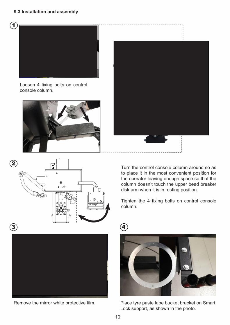
9.3 Installation and assembly
1
2
3 4
Loosen 4 fixing bolts on controlconsole column.
Turn the control console column around so as toplace it in themostconvenientpositionfortheoperatorleavingenoughspacesothatthecolumndoesn’ttouchtheupperbeadbreakerdisk arm when it is in resting position.
Tighten the 4 fixing bolts on control consolecolumn.
Removethemirrorwhiteprotectivefilm. PlacetyrepastelubebucketbracketonSmartLock support, as shown in the photo.

11
Fig.2
Mount the hook for the brush on the inner side ofthe control console column.
Thepneumaticnetworkoftheinstallationareamustbeprovidedwithmin.8barworkingpressure outlet.
- Connect the machine to the compressed air network by means of the air connection unitlocated at the rear side of the machine (Fig.2).
9.5 Connection to the compressed air network
9.4 Connection to the electrical networkThe installation site should be equipped with an electrical system with adequate grounding circuit.Connectthemachinetoanelectricalpowersocket230V/1Ph/50-60Hzprotectedbysafetycircuitbreakerwiththefollowingfeatures:
-InterventionratedcurrentIn=20A,C curveaccordingtoIEC/EN60898standard-DifferentialcurrentId=30mA
NOTE: Ifthemachineissuppliedwithouttheelectricalplug,theusershallfitonethatissuitableforthevoltageofthemachine and complies with current regulations.
9.6 Laser pointers calibrationBefore starting demounting/mounting a tyre, please check positioning of laser pointers using a special calibration jig supplied with the standard accessories of the machine.Followtheinstructionsinchapter32.2onpag.35.
Positionthelifterplatform(optional)soastoalignitsholewiththepin.Tightenthescrewsfirmly,asshown in the photos.
5
6
7
8
12
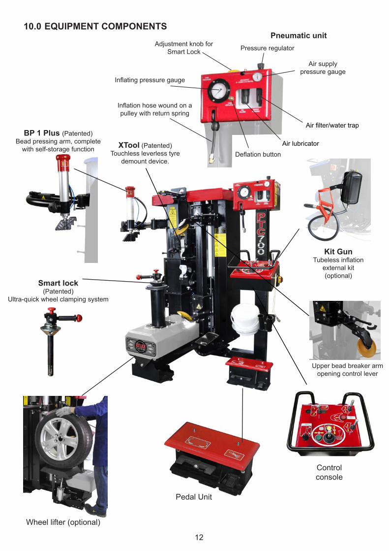
10.0 EQUIPMENT COMPONENTS
Upperbeadbreakerarmopeningcontrollever
Pneumatic unitAdjustmentknobfor
Smart Lock Pressureregulator
Inflationhosewoundonapulley with return spring
Inflatingpressuregauge
Airsupplypressure gauge
Airfilter/watertrap
AirlubricatorDeflationbutton
BP 1 Plus (Patented)Bead pressing arm, complete
with self-storage function
Smart lock(Patented)
Ultra-quickwheelclampingsystem
PedalUnit
Control console
Kit GunTubelessinflation
external kit(optional)
Wheellifter(optional)
XTool(Patented)Touchlessleverlesstyre
demountdevice.

13
11.0 CONTROLS DESCRIPTION AND FUNCTION CONTROL
Any testing must be carried out without any tyre on the machine.Watch out for any component which could interfere with machine testing operations.
1-Clockwise and counterclockwise clamping chuck (ref.14)rotationcontrolpedal2-Wheelliftercontrolpedal(up/down), optional3-Inflationpedal4-STEP 1:Rim diameter and width setting joystick 5-STEP1: Laserverticalmovementenablingbutton 6-STEP 2:Lowerbeadbreakerdiskcontrollever(up/down)7-STEP 2:Upperbeadbreakerdiskcontrollever(up/down)8-STEP 2:Bead breaker disks radial“over-run”button
9-STEP 3:Demountingtoolcontrollever10 - Air supply11-STEP 4:Mounting tool selector switch12-Deflationbutton13-Beadpressingarmcontrolbuttons(up/down)14-Clamping chuck15-Bead breaker disks16-Mounting/demounting tools17-STEP 1 : Laserhorizontalmovementenabling button 18-MainPowerSwitch19-Upperbeadbreakerarmopeningcontrollever
2
13 12
14
16
31
45
6
789
11 17
18 1015
19

14
12.0 RIM AND TYRE IDENTIFICATIONBeforestartingdemountingatyre,itisofCRUCIALIMPORTANCEtoidentifythemeasurementsoftherimandofthetyre, as well as to make sure that neither the rim nor the tyre are damaged.
WARNING: theseveryimportantprocedureshavetobeperformedcorrectlytoreduceanyrisksoftyreburstingwhilere-mountingandinflatingthetyreontherim.
Each rim bears an indication of their diameter, width, number of humps etc.Example: 8Jx15H2
A=8 Nominalwidthoftherimininches(1inch=25.4mm)B=J SizeoftheflangeC=15 NominaldiameteroftherimininchesD=H2Doublehump(beadretentionsystem)
Each tyre bears a considerable amount of details, among which are thedimensions, type and maximum speed.
Example: 205/65 R 15 91H TL
A=205Widthofthetyre(thedistancebetweentyresides,expressedinmillimetres).B=65 Ratiopercentagebetweenthewidthofthesectionanditswidth.C=R Typeoftyre(R=radial).D=15Indicatesthekeyingdiameterininches(diameterofwheel),which must be the same as the rim.E=91 Indexofthemaximumloadbornbyeachwheel.F=H Maximumadmittedspeedofthetyre(H=210Km/h)G=TLTypeoftyre(TL=Tubeless)
WARNING:Itisstrictlyforbiddentomounttyresonrimswithmismatchingparameters(diameterandwidth).Itisalsoforbiddentomounttyreswithdimensionswhicharedifferentfromtheonesstated in the car logbook.
8J x 15H2
A DB C
AFECB DG
13.0 VALVE POSITION
Thepictureontherightsiderepresentsarimasaclockface(viewfromthetop).ThevalveorthetoolpositiondescribedbythefollowingworkingstepsALWAYSrefer to the represented clock-face hours-marks.
WARNING :To avoid damaging the valve or the pressure sensor, whereinstalled,youmustalwayssetthevalveintothepositionindicated,following the instructions during bead breaking, mounting anddemounting operations.
15
fig.1
14.0 WHEELS AND TYRES CLASSIFICATION
14.1 Standard wheels
A“standardwheel”isacarwheelwithsteeloralloyrim,withcenterhole,drop centre close to the external border of the rimandastandardtyre(neitherRUN-FLATnorLowProfile).
14.2 Low-profiled tyres (UHP) wheels
Lowprofiletyres(UHP)arethoseinwhichtheheight(H)andthewidth(C)havearatiolowerthan0.5(i.e.lowprofileseries45standsforaaspectratioofH/C=0.45).Fortyrestobeconsideredaslowprofile(UHP),theymustalsohaveamaximumspeedcodeequalto/orhigherthanV.
Maximum speed codesQ=to160km/hR=to170km/hS=to180km/hT=to190km/h
14.3 RUN-FLAT tyres wheels
RUN-FLATtyresarethosewhichallowtocontinuetodrivethevehicleforapresetnumberofmilesandatapresetspeed,eveniftheyhavenointernalpressure.Theseparameterschangefromonemanufacturertoanother.Themarketcurrentlyoffers2differenttypesofRUN-FLATtyres:-Thosewithreinforcedsidewall(self-supporting)where,thankstoadifferentmixandareinforcedstructure,theshoulderofthetyrecanbeartheweightofthevehicleevenwhentheinternalpressureofthetyreiszero.-Thosewithinternalsupportwhichhavearinginsidetherimthatbearsthesidewallofthetyrewhenthereisnopressureinsideit.Theinternalsupportmaybemadeofplastic(Pax-Sistem)orofmetal(Support-Ring).
Allthetyreswhichdonotcorrespondtotheabovementioneddescriptionshavetobeconsideredas“standardtyres”.
ThisTyre-Changerisabletohandlealltypesofwheelswith“standard”tyres,LowProfile(UHP)andRUN-FLATtyreswith reinforced side.RUN-FLAT tyres with internal support (PAX System or Support-Ring type) mounting/demounting procedures needspecial accessories to be used according to precise dedicated instructions.
It is compulsory to follow the demounting/mounting instructions carefully, in order to avoid tyre damages and the consequent risks for the vehicle and the passengers safety.
U=to200km/hH=to210km/hV=to240km/h
W=to270km/hZR=>240km/hZR(Y)=>300km/h
15.0 WDK RULESWDKisaGermancertifiedbodychargedwiththeevaluationoftyre-changersfunctioningandtheircapabilitytoperformgoodandsafeoperationsonRUN-FLATandUHPtyrescorrectly,toavoidpermanentand potentially dangerous damages to tyres.In order to perform a correct demounting and mounting process, the following premises are strictly compulsory:
1.Guidelinesknowledge-WDKliteratureprovidesallnecessaryguidelinesforalltyrebrandsandmodels,includingalltheoreticalandpracticalinstructionstoavoidanypossibledamagetotyre,rimandpressure sensor.2.Certifiedtyre-changer-ThisTyre-ChangercanbedeliveredwithWDKaccessoriestofulfilallWDKrequirements.3.TomeettherequirementsoftheWDKprocedure,thepneumaticbeadpressingarmmustbeusedwiththespecificbeadpressingtool(showninthepicturebeside).4.Qualifiedoperator–ThespecifictechnicalcoursesprovidetheoperatorswiththenecessaryWDKguidelinesandserviceinstructions.DedicatedWDKofficialcoursesareavailabletogettheWDKdiploma, when necessary.
WDKBeadpressing tool(optional)

16
16.0 WHEEL POSITIONING AND CENTERING ONTO CLAMPING CHUCK (OPTIONAL)Beforeliftingandpositioningthewheelontotheclampingchuck,removeallthecounterweightsfromtherimusinganappropriatetool,beingcarefulnottodamagetherimitself.Removeanyobjectortoolwhichcouldinterferewiththewheel lifter (availableasoptional).-Putthewheelverticallyontothewheellifter(optional),sothatinsideofrimfacestyrechanger(Fig.1).-Pressthecontrolpedalref.3toliftthewheelandpositionitontoclampingchuck.Oncethewheelisovertheclampingchuck, align the central hole of the rim with the rotation axle of the clamping chuck. Rotate the wheel in order to match oneofthelugholeswiththedrivingpinoftheclampingchuck(Fig.2).-Lower the lift by releasing pedal ref. 3. -Reversemountedwheelsshouldalwaysbepositionedandclampedon theclamping chuckupsidedown.Whenclamping,useFRRQuickwheelclampingadaptorforreversemountedandplasticcladwheels(availableasoptional,seepage31).FollowtheinstructionsgiveninFRRQuickmanual.
Fig.2
Clamping chuckDrivingpin3-Wheelliftercontrol pedal
Fig.1Wheellifter(optional)
17.0 WHEEL CLAMPING OPERATION WITH SMART LOCK (PATENTED)
-Patentedultra-quickwheelclampingsystemmakesiteasierforoperatorstoperformatoughandsteadywheelclampingbysimplyturningalever.
- The clamping is performed by an expanding nut. Both strength and grip can be easily calibrated by acting on itsadjustment button and by means of an appropriate adjustment knob.
-SMARTLOCKweighsjust:4,5Kg.

17
Wheel clamping operation with Smart LockLockinglever
SMART LOCK introduction /extraction handle.
Centering cone
Expanding nut
Elastic rubber rings(OR3093)
Conical terminal
Check the correct wheel positioning onto the clamping chuck.InsertSMARTLOCKmakingthecenteringconefittherimholecorrectly,leavingnospaceamongSMARTLOCKnut,therimandthetyre-changerclampingchuck.
Keeping the handle pressed down (to avoid eventual residual plays), tilt thelockingleververtically.
Duringwheelclampingoperationthequick-releasesystemmovesautomaticallyto hooking position (click).Check the perfect wheel locking onto the clamping chuck before performing any bead breaking, demounting or mounting operation.
Plasticprotectiontoavoidanydamageto
alloy rim
Wheel unlockingOncetheoperationsontothewheelarecompleted,liftuptheQuick-Releasesleeve.
TiltdownthelockinglevertounlockSMARTLOCK,inorder topullout the lockingnutandremove thewheel from the clamping chuck.
1
2
3
1 2 3
4
5
5
CL
ICK
4
Quick-Releasesleeve
17.1 Tightening adjustment
TheclampingforceofSMARTLOCKcouldbeloosenedafteralongtimeusebyaprogressivewearingofsomecomponents,thisrevealedbyaprogressiveslackofthelockinglever.
Torestore/increase/decreasetheSMARTLOCKtightening:presstheyellowadjustmentbuttonand,bymeansoftheadjustmentknob(standardsupplied),startturningmanuallytheconicalterminalthusactingontheexpandingnut.Then,release the button and keep on turning the conical terminal until the button pops up again.
Tighteningstrengthadjustmentbutton(yellow).
- +Adjustment
knob
+ Rotate clockwise to increase the clamping force
- Rotate counterclockwise to decrease the clamping force
18
Fig.2Fig.1
1
2
B
2
1
A 4
ON
OFF
1 2 3 4
E E
F F
Il presente disegno è proprietà della Giuliano Group SpA e non può essere riprodotto o ceduto a terzi previa autorizzazione scritta
GREZZO
PESI SEMILAVORATI Kg.
MATERIALE
TRATT. TERMICO
DUREZZA
COD. MAT. GREZZ0
TRATT. SUP.
ISQ 87SEGUIRE LA SEGUENTE ISTRUZIONE:PER LE TOLLERANZE NON INDICATE SUL DISEGNO
p
SALDATURA AD ARCO CONFILO ANIMATO IN
ATMOSFERA DI GAS ATTIVO (80%Ar , 20% CO2)136
135 DI GAS ATTIVO (80%Ar , 20% CO2)
SALDATURA AD ARCO CONFILO IN ATMOSFERA
DESCRIZIONE
da S235
DOMEX 490÷740
a S355
T1
TIPO DI ACCIAIO
C20 ÷ C60
Sm x45°
R=
SMUSSINON QUOTATI
RACCORDINON QUOTATI
TOGLIERE TRUCIOLIE SPIGOLI VIVI
DATA:
UNITA' DI MISURA mm
MACCHINA
DIMENSIONI ISO
DISEGNO MOD.
SCALA: 1:1
N° PEZZI PER MACCHINA
DISEGNATORE
COD.LAV.DENOMINAZIONE
DIMENSIONI DA CONTROLLARE
FINITO
CODICE DI CONDIVISIONE
PROCEDIMENTI DI SALDATURA p (UN IEN 22553)
Dra
w2
1 2 3 4
A A
B B
C C
D D
DECALCO PULIZIA SMART LOCK
E MANDRINO 30 41521
SMTG
14/09/2016
Colognesi
Avery 806 YellowE806
CC
03/10/2017: C) Aggiunta fase di regolazione (Vezzani)10/10/2016: B) Modificata numerazione fasi di pulizia (Vignoli)18/05/2016: A) Modificata grafica adesivo ok Pellicciari
16
981
17.2 Maintenance -TheregularcleaningandlubricationoftheSMARTLOCKcomponents grant a long-lasting correct functioning of the tool.1- Clean the expanding nut with the metallic brush or use the standard supplied cleaning brush for Smart Lock.2-Blowcompressedairtoremovedirt.3- Clean the clamping chuck inner surface using the standard supplied cleaning brush.4-Blowcompressedairtoremovedirt.-PeriodicallylubricateallmovingmechanicalpartswithCRCorsimilar.- The replacement of 2 rubber rings (OR3093)isrecommendedevery12÷18monthsuseofSMARTLOCK.
18.0 SWITCHING ON/OFF18.1 Machine start up
- Turn the yellow/red main power switch clockwise(ref.18,page13).
18.2 Switching off the machine (an emergency stop)
- Turn the yellow/red main power switch counterclockwise(ref.18,page13).
STEP 1: rim diameter setting
-KeepingbuttonA pressed down, while simultaneously acting on the joystick (4)withhorizontalmovement(ref.1,Fig.1)andbringtheLASERpointerontotheedgeoftherimtoplaceitaccordingtoitsdiameter.
19.0 RIM SETTING - STEP 1
STEP 1: rim width setting
-PressandholddownbuttonB, while simultaneously acting on the joystick (4)withverticalmovements(ref.2,Fig.1)andbringtheLASERpointerontotheedgeoftherimtopositionitaccordingtothecorrectheightoftheupperrimedge.
WARNING:Before carrying out any operation on the wheel make sure that pointers are correctly positioned as showninpicture2toavoidanydamagetotherimortyre.
19
TPMSvalve
Traction point
20.0 Tyre Pressure Monitoring System(TPMS)TPMS,TyrePressureMonitoringSystemisanelectronicsystemdesignedtomonitortheairpressureinsidethetyresthrough special sensors mounted inside the wheels, which provide real-time tyre-pressure information and insidetemperaturedatatothevehicle’selectroniccontrolunit.Tyrepressuresystemalertsthedriverwhenthetyrepressurefalls 20% below the recommended pressure, thus increasing your safety on the road.ThischapterdescribesthecorrectpositioningofTPMSvalveduringthedifferentworkingstages,inordertoavoidanydamage.
Bead breaking:PlaceTPMSvalveat “2:00o’clock”position.Startpushingon thetyre bead using the upper bead breaker disk.
Upper bead demounting:Spintheclampingchuck(clockwise)bypressingthepedal1 until the valvereaches“1 o’clock”position(at about 10 cm from the demounting tool)so as toavoidpossible damagestotheTPMSvalve.
Warning: rim and tyre must spin together as one during bead demountingoperations,toavoiddisplacementofTPMSsensor.
Lower bead demounting, with demounting tool:Place TPMS valve below the demounting tool at “12:00 o’clock”position.
Lower bead demounting, with bead breaker disk:PlaceTPMSvalvetowardsthebeadbreakerdisk.
Lower bead mounting:PlaceTPMSvalveat“5:00o’clock”position,inanycaseatabout10cm from traction point.
Upper bead mounting:PlaceTPMSvalveat“5:00o’clock”position,inanycaseatabout10cm from traction point.
Demounting tool positioning:Place TPMS valve at “2:00 o’clock” position. Bring the demounting tool into working position. Whilespinning the wheel, insert the demounting tool into the dropcentrelevel.Stoptyrerotationwhenthevalvereaches11o’clockposition.
20
fig.1
fig.3
19
7
8
fig.2
Check for correct centering and locking of the wheel onto the clamping chuck.
21.1 Upper bead breaking
-Before starting any operation, check the correct centering and locking of the wheel onto the clamping chuck.-Beforestartinganyoperation,pleasecheckeventualpresenceofaTPMSpressuresensor.Ifso,checkitsefficiencyusing an appropriate tool.-Itispossibletounlockthedisksupportandenableaspringloadedmovement,changingtheangleofthedisk,increasingitspenetrationinsidetherim.Particularlyeffectivewithsofttyres.
Make sure the tyre is completely DEFLATED before starting any operation on the wheel.
21.0 BEAD BREAKING - STEP 2-
-Spintheclampingchuckuntilthevalvereaches“2 o’clock”position.
-Bringtheupperbeadbreakerdiskdownuntilittouchesthetyreusingcontrollever7forliftingandlowering(up/down).
- Start spinning clockwise by pressing pedal 1 (page13).
Note:theclampingchuckcanspinat2differentspeeds,accordingtooperator’spreferences.
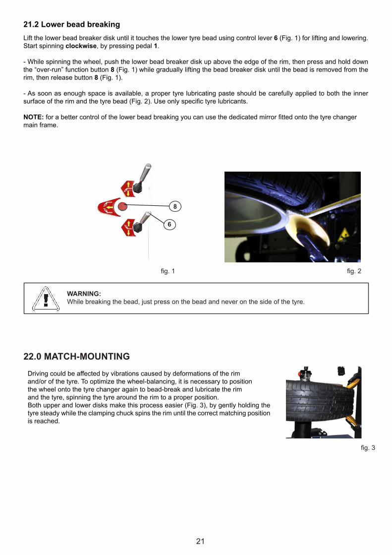
-Whilespinningthewheel,pushtheupperbeadbreakerdiskdownbelowtheedgeoftherim,thenpressandholddownthe“over-run”functionbutton8 (Fig.2) whilegraduallyloweringthebeadbreakerdiskuntilthebeadisremovedfromthe rim, then release the button 8 (Fig.2). -Assoonasenoughspaceisavailable,apropertyrelubricatingpasteshouldbecarefullyappliedtoboththeinnersurfaceoftherimandthetyrebead(Fig.1).Useonlyspecifictyrelubricants.
During bead breaking operations, check thecorrectpositioningofTPMSpressure sensor (ifany), usual-lyinsertedintothevalveoftherim.Wrongmovementsofthebeadbreakerdiskscoulddamagethesensor.AvoidanycontactbetweenthelubricatingpasteandTPMSpressure sensor, if any.
-Oncethebeadgetsloosened,raiseandmoveawaytheupperbeadbreakerdiskbyactingonlever7 (Fig.2).
-Once the bead breaker disk is out of therim,itispossibletomovethebeadbreakerdisk arm away from the working position by actingonlever 19(fig.3).
19
21
fig.2
fig.3
fig.1
8
6
Lift the lower bead breaker disk until it touches the lower tyre bead using controllever 6 (Fig.1) for lifting and lowering.Start spinning clockwise, by pressing pedal 1.
-Whilespinningthewheel,pushthelowerbeadbreakerdiskupabovetheedgeoftherim,thenpressandholddownthe“over-run”functionbutton 8 (Fig.1)whilegraduallyliftingthebeadbreakerdiskuntilthebeadisremovedfromtherim, then release button 8 (Fig.1).
-Assoonasenoughspaceisavailable,apropertyrelubricatingpasteshouldbecarefullyappliedtoboththeinnersurfaceoftherimandthetyrebead(Fig.2).Useonlyspecifictyrelubricants.
NOTE:forabettercontrolofthelowerbeadbreakingyoucanusethededicatedmirrorfittedontothetyrechangermain frame.
21.2 Lower bead breaking
WARNING:Whilebreakingthebead,justpressonthebeadandneveronthesideofthetyre.
22.0 MATCH-MOUNTING
Drivingcouldbeaffectedbyvibrationscausedbydeformationsoftherimand/orofthetyre.Tooptimizethewheel-balancing,itisnecessarytopositionthe wheel onto the tyre changer again to bead-break and lubricate the rimand the tyre, spinning the tyre around the rim to a proper position.Both upper and lower disks make this process easier (Fig.3), by gently holding the tyre steady while the clamping chuck spins the rim until the correct matching position is reached.
22
Fig.2
Fig.3
Fig.4
9
23.0 TYRE DEMOUNTING - STEP 3-Oncethebeadbreakingprocessiscompleted,andthewheelisalreadypositionedontotheclampingchuck,checkand ensure its locking and centering.
23.1 Upper bead demounting
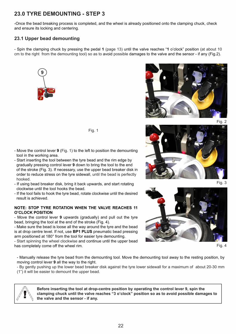
- Spin the clamping chuck by pressing the pedal 1 (page13)untilthevalvereaches“1 o’clock”position(at about 10 cmtotherightfromthedemountingtool)soastoavoidpossible damagestothevalveandthesensor-ifany(Fig.2).
-Movethecontrollever9 (Fig.1) to the left to position the demounting tool in the working area.- Start inserting the tool between the tyre bead and the rim edge by gradually pressing controllever 9 down to bring the tool to the end ofthestroke(Fig.3).Ifnecessary,usetheupperbeadbreakerdiskin order to reduce stress on the tyre sidewall, until the bead is perfectly hooked.- If using bead breaker disk, bring it back upwards, and start rotating clockwise until the tool hooks the bead.- If the tool fails to hook the tyre bead, rotate clockwise until the desired resultisachieved.
NOTE: STOP TYRE ROTATION WHEN THE VALVE REACHES 11 O’CLOCK POSITION -Move the control lever 9 upwards (gradually) andpull out the tyrebead,bringingthetoolattheendofthestroke(Fig.4).- Make sure the bead is loose all the way around the tyre and the bead isatdropcentrelevel.Ifnot,useBP1 PLUS pneumatic bead pressing armpositionedat180°fromthetoolforeasiertyredemounting.- Start spinning the wheel clockwise and continue until the upper bead has completely come off the wheel rim.
-Manuallyreleasethetyrebeadfromthedemountingtool.Movethedemountingtoolawaytotherestingposition,bymovingcontrollever 9 all the way to the right.- By gently pushing up the lower bead breaker disk against the tyre lower sidewall for a maximum of about 20-30 mm (1”)itwillbeeasiertodemounttheupperbead.
Before inserting the tool at drop-centre position by operating the control lever 9, spin the clamping chuck until the valve reaches “3 o’clock” position so as to avoid possible damages to the valve and the sensor - if any.
Fig.1

23
fig.2fig.1
fig.3 fig.4
8
6
9
23.2 Lower bead demounting
-Beforepullingoutthelowerbead,spintheclampingchuckuntilthevalvereaches“3o’clock”positionso as toavoidpossibledamagestothevalveandthesensor-ifany.
-Bringthelowerbeadbreakerdiskupbyoperatingthecontrollever 6 (Fig.1) to lift the tyre until the lower bead is about10mmovertheupperrimedge(Fig.2).Pressandholddownbutton8 (Fig.1)toactivatethe“over-run”functionand bring the disk close to the rim.
- Spin the wheel clockwise until the tyre comes off completely.
- Check the status of the pressure sensor - if any - and replace it if necessary. -Oncetheoperationsarecompleted,movethelowerbeadbreakerdiskawayfromtheworkingposition.
NOTE: rim and tyre must spin together as one.-Inordertohelpthelowerbeadcomingoutandtoreducethestresstothetyre:inserttheplasticleverandspinthewheel clockwise.
23.3 UHP and RUN-FLAT tyres demounting
-SomepreciseandcarefuloperationsarenecessarytodemountUHPandRUNFLATtyres.ItiscompulsorytofollowWDKrulestoavoidpermanentdamagestothesetyres.-UpperbeaddemountingofUHPorRunflattyrescanbeperformedbyinsertingthedemountingtool(Chapter23.1)insidethetyreandreachingthedropcentrelevel.Atthisstage,placeBP1 PLUS pneumatic bead pressing arm on the oppositesideofthedemountingtoolandpressthesidewalltofacilitatethefittingofthebeadinsidethedrop-centre.-Graduallypressthecontrollever9 (Fig.4)all the way up, and pull out the tyre bead, bringing the tool upwards at the end of the stroke.-By gently pushing up the lower bead breaker disk against the tyre lower sidewall for a maximum of about 20-30 mm (1”)itwillbeeasiertodemounttheupperbead.-Inserttheredplastictyrelever(Fig.3)- Start spinning the wheel clockwise and continue until the upper bead has completely come off the wheel rim.- Manually releasethetyrebeadfromthedemountingtool.Movethedemountingtoolawayfromtheworkingposition,bymovingthecontrollever9 (Fig.4) all the way to the right.-Thedemountingprocedureofthesecondbeadissimilarto“standard”tyre(Chapter23.1).

24
7
8
fig.1
fig.2 fig.3
24.0 TYRE MOUNTING - STEP 4-Checktherimandthetyrecarefully,asperinstructionsintherelevantparagraphofthismanual.
-Iftherimhasbeenremoved,clampitagainontotheclampingchuckasperinstructionsinparagraph“Wheelclam-pingoperationwithSmartLock”ofthismanual.Makesurethetwolasersarecorrectlypositionedontherimedge.
- Carefully lubricate the whole inner surface of the rim and the beads of the tyre, both externally and internally right aroundthecircumference,forawidthofatleast3cm(Fig.1).
Avoid any contact between lubricating paste and pressure sensor, if any.
24.1 Lower bead mounting-Placethetyreontotherim,tiltingthetyreto“3o’clock”positioninordertomakethebeadgoundertheupperrimedge,takingcareofpositioningthevalveat“5o’clock”position(Fig.3).-Bringtheupperbeadbreakerdiskdownuntilittouchesthetyreusingcontrollever7 (Fig.2)for lifting and lowering (up/down).- Rotate the wheel clockwise by pressing pedal 1 (page13),whilemanuallypressingthetyrein“5o’clock”positionuntilthelowerbeadreachesthedropcentrelevel.Keepthetyrepressedwhilerotatingtocompletethelowerbeadmounting.
WARNING:Rim and tyre must spin together as one.
25
fig.2
fig.3
fig.1
fig.4
fig.5 fig.6
11 Position 1
Central position (0)
24.2 Upper bead mounting
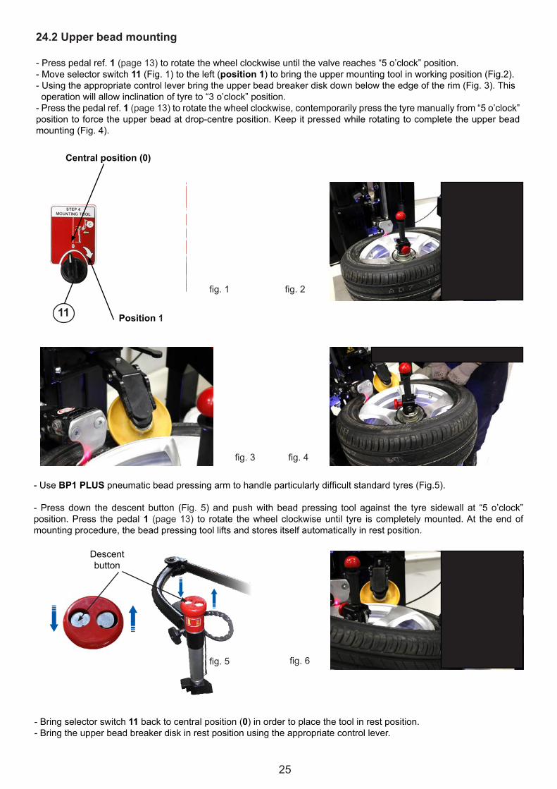
- Presspedalref. 1 (page13)torotatethewheelclockwiseuntilthevalvereaches“5o’clock”position.-Moveselectorswitch11 (Fig.1)totheleft(position 1)tobringtheuppermountingtoolinworkingposition(Fig.2).-Usingtheappropriatecontrolleverbringtheupperbeadbreakerdiskdownbelowtheedgeoftherim(Fig.3).Thisoperationwillallowinclinationoftyreto“3o’clock”position.-Pressthepedalref.1 (page13)torotatethewheelclockwise,contemporarilypressthetyremanuallyfrom“5o’clock”positiontoforcetheupperbeadatdrop-centreposition.Keepitpressedwhilerotatingtocompletetheupperbeadmounting(Fig.4).
-UseBP1 PLUSpneumaticbeadpressingarmtohandleparticularlydifficultstandardtyres(Fig.5).
-Pressdown thedescentbutton (Fig. 5) andpushwithbeadpressing tool against the tyre sidewall at “5o’clock”position.Press thepedal1 (page13) to rotate thewheelclockwiseuntil tyre iscompletelymounted.At theendofmounting procedure, the bead pressing tool lifts and stores itself automatically in rest position.
- Bring selector switch 11 backtocentralposition(0)inordertoplacethetoolinrestposition.-Bringtheupperbeadbreakerdiskinrestpositionusingtheappropriatecontrollever.
Descent button

26
Fig.1
Fig.4 Fig.5
11
24.3 UHP and RUN-FLAT tyres mounting
-LowerbeadmountingofUHPorRunflattyrescanbeperformedbyusingtheupperbeadbreakerdiskonly(page24).Rotatetherimclockwiseuntilthevalvereaches“5o’clock”position.Putthetyreontherimtilteddownto“3o’clock”position. Lower the upper bead breaker disk on the shoulder of the tyre, rotate the wheel clockwise and simultaneously push down the bead breaker disk to complete the mounting.-Oncethelowerbeadismounted,rotatetherimuntilthevalvereaches“5o’clock”position.Pressthetyrebytheupperbeadbreakerdiskuntilthebeadreachesdrop-centrelevel.Movetheselectorswitch11 (Fig.3)totheleft(position 1)and insert the mounting tool into the tyre.- Usethebeadpressingclamp(standardsupplied)togetherwiththeproperrubberprotection(•steelrim,••aluminiumrims,•••aluminiumrimswitharchedspokes)(Fig.1).Lockitontotherimedgewiththevalveat“5o’clock”position.Pressthetyrebeadwiththeupperbeadbreakerdisktofacilitatepositioningandlockingoftheclamp.-SpinslightlyandfitBP1 PLUSbeadpressingtoolbetweenthediskandtheclamp.Pressthetyreuntiltheupperbeadreachesdrop-centrelevel(Fig.4).-InaccordancewiththeWDKprocedure,thepneumaticbeadpressingarmmustbeusedwiththeWDKbeadpressingtool(Fig.2,optionalaccessory).- Start spinning the wheel making sure that the whole tyre bead is right inside the drop-centre.- If this necessary condition for a correct mounting is not accomplished, use the pneumatic bead pressing arm and pushthetyresidewalltofittheupperbeadintothedrop-centre(Fig.5).
-Goonspinningthewheeluntiltheupperbeadiscompletelymounted.-Removetheclampandtherubberprotectionwiththehelpofbeadpressingarmorbead breaker disk. Removethebeadpressingarmandmovethetoolinrestpositionbyrotatingtheselectorswitch 11 to the center posi-tion(0).Liftthebeadbreakerdiskupandbringittorestpositionusingthecontrollever 7.-Keepthewheellockedontotheclampingchuckduringtheinflatingoperations.Readtheinflatinginstructionscarefully.-Oncethetyreinflationiscompleted,unlockthewheelandbringitdownontothefloor,takingadvantageofthewheelpositioningdevice.
Rubber protectors WDKBeadpressingtool(optional)
WARNING:In these last phases, work very carefully to avoid straining the side of the tyre excessively.
Fig.2
Fig.3Position 1
Central position (0)
27
3
25.0 INFLATION
If tyre had to burst or rim had to break under pressure, operators could beseriously injured or even killed.
During inflation use personal protective equipment to protect hearing and sight.
Make sure the rim and tyre are the same size.
Also check the conditions of the tyre and rim to make sure there are no defects beforestarting to inflate.
Inflate the tyre with brief jets of air checking the pressure on the gauge frequently.
This Tyre-Changer is automatically limited to an inflation pressure of 3,5 bar (50 psi).NEVER EXCEED THE PRESSURE RECOMMENDED BY THE TYRE MANUFACTURER.
Keep hands and body as far away as possible from the tyre during inflation.
Tyres must be inflated with the utmost caution. The instructions below have to be read andfollowed strictly.This Tyre-Changer is NOT designed to protect operators and objects from accidental tyresexplosions.
ATTENTION: If tyre bead fails to fit in place at 3.5 bar pressure, it is necessary to repeat the beadloosening and lubricating procedures before trying again to inflate the tyre.
Inflationhosewoundonapulley with return spring
Inflatingpressuregauge
Airsupplypressure gauge
Deflationbutton
Inflationpedal
•Connecttheinflationhosetothevalveofthetyre.•Makesuretherimandthetyrehavethesamediameter.•Makesuretherimandtyrearesufficientlylubricated;lubricateifnecessary.•Pressandreleasetheinflationpedal(3)frequently,checkingthepressureonthepressuregaugeuntilthetyrebeadfitscompletelyontotherim.•Continueinflatingtoreachthepressurerecommendedbythetyremanufacturer.Alwaysinflateinshortblasts
and constantly check the pressure in the process.
•Pressthedeflationbuttontodeflatethetyreincasethepressureexceedsthevaluerecommendedbythetyremanufacturer.
NOTE: Sometimes, regular inflation may not be enough to seat the bead of tubeless tyres. This problem may be solved by using the optional accessory TUBELESS TYRE BEAD SEATING SYSTEM (GUN, ref. page 32).

28
Tubelessinflationexternalkithelpsseatingthebeadproperlyduringinflationoperations,whenservicinglowprofiledtyres.InordertoproperlyusetheoptionalTubelesstyrebeadseatingsystem:
•Pressthesafetyvalveagainsttherimedge,pushtheactivatingbuttonontothe handle to blast air, while simultaneously pressingtheinflationpedal(3)inordertofeedthewheelvalve.
Activatingbutton
Safetyvalve
25.1 Tubeless tyre inflation (optional)
Duringtheinflationstages(andespeciallyduringthebeadseatingoperation),itisrecommendedtowearanappropriatepersonalprotectiveequipmenttoprotecttheauditoryapparatusfrompossibleblastinjuriesandfromnoiselevelsthatsometimesexceedthepermittedthreshold.
Usealsoappropriateeyeprotectionsequipmenttoshadeyoureyesfromanypossibledebristhatmightflyduetothehighpressureinvolvedintyrebeadseating.
Thejetofairthatcomesoutwhentheinflatingdeviceisonhasaveryhighpressure:holdthehandlefirmlywithyourhandtoavoidanysortofbacklash.

29
X 2
X 2
26.0 STANDARD ACCESSORIES (STANDARD SUPPLIED)
-Lube paste bucket-Brush
-Plastictyrelever.TobeusedduringtyredemountinginaccordancewithWDKprocedure.
-Kitofnylonprotectorsformountingtool
-PlasticprotectionsforSmartLockcenteringcone
- Rubber protections for clamping chuck faceplate
-PlasticconeØ70mmforclampingspecialalloyrims
- Reducing ring for clamping chuck faceplate.Tobeusedtofitparticularalloyrims.

30
X 2
-AdjustmentknobforSmartLock
- Cleaning brush for Smart Lock and clamping chuck inner surface
-SpareOringsforSmartLock
-Plasticprotectionsforclampingchuckdrivingpin
-Plasticbeadpressingclampwithextra insert for rim edge with specialinclination. To be used together with rubberprotectionsformountingUHPandRUNFLATtyreaccordingtoWDKprocedure.
- Rubber protector for steel rims.(markedwith•)
- Rubber protector for aluminium rims(markedwith••)
- Rubber protector for aluminium rims witharched spokes.(markedwith•••)
-Airlubricator,airfilter/watertrap
- Calibrationjigandmagnet(seedetailsinchapter32.2)

31
27.0 OPTIONAL ACCESSORIES
Art. FRR QUICKWheelclampingadaptorforreversemountedandplasticcladwheels on center post tyre changer. Standard supplied with measuringcaliperandtwokitsofpins(6pins70mmlength;6pins100mmlength).Youcanhandlerimswith3,4,5or6lugholes(andtheirmultiples)in different shapes and design.
3 lug holes 4 lug holes
5 lug holes 6 lug holes
Reverse mounted wheelsSpecial rims
LTK3Centering cones adaptor kit for light-truck rimslocking(centrehole:Ø120toØ190mm).
LTK4Centering cones adaptor kit for light-truck rims locking(centrehole:Ø140toØ220mm).
LTK6Centering conical adaptor for steel rims locking (centrehole:Ø75toØ120mm).
LTK5Two-sides centering conical adaptor for steel rimslocking(centrehole:Ø75toØ145mm).

32
GUNTubelessinflationexternalkit
Art. UHP WDKKitforJBOSS
WL6Wheellifterforwheelpositioningandcenteringontoclampingchuck.LiftingcapacityKg.80
SPK 1 (LAMBORGHINI)NYLONCONEFORSPECIALLAMBORGHINIWHEELS,allowsclampingwheelswith center hole diameter from 55 to 85 mm.
SPK 2 (PORSCHE)NYLONCONEFORSPECIALPORSCHEWHEELS,allowsclampingwheelswith center hole diameter from 60 to 85 mm.
SPK 3(BMW)NYLONCONEFORSPECIALBMWWHEELS,allowsclampingwheelswith center hole diameter from 55 to 70 mm.

33
General precautions-Avoiddirectandprolongedcontactwithskin.-Avoidtheformationofoilmistsintheair.-Avoidsplashing.-Wearappropriateclothing,glovesandgogglestoprotectagainstoilsplashes.- Do not use greasy rags.- Do not eat or smoke if your hands are soiled with oil.
First Aid instructions-Ifoilisswallowed,doNOTinducevomitingbutgoimmediatelytothenearestmedicalcentrewithinformationonthetype of oil swallowed.- If oil gets in eyes, rinse abundantly with water until irritation ceases, then go to the nearest medical centre.-Ifoilcomesintocontactwithskin,rinseabundantlywithneutralsoapandwater.donotusesolventsorirritantproducts.
Disposing of used oilDo not throw used oil away outdoors or pour it on the ground.Drainintoasuitablecontainerandforwardtospecialisedoildisposalcentres,orhanditovertoauthorisedcollectioncompanies.
Oil spillages or leakagesEliminate the cause of the leakage and stop the oil spillage from spreading using absorbent material. Clean the area where theoilhasspilledusingdegreasingdetergentstopreventslippinganddisposeofthewasteaccordingtocurrentstateandnationalregulations.CleanuptheoilandsendtospecialdisposalcentresaccordingtocurrentNationalregulations.
31.0 OIL TREATMENT
OIL IS POLLUTANT! DO NOT THROW AWAY OUTDOORS OR POUR ON THE GROUND.Clean up the oil and send to special disposal centres according to current national laws.
28.0 RE-POSITIONINGTore-positiontheTyre-Changerinanewworkplace:securethemovingparts(i.e.thebeadpressingarms,etc.)disconnectallthepowersourcesandinstallitagainfollowingalltheinstructionperchapter9.0(INSTALLATION)ofthis manual.Connections to power sources and connection & inspections of the safety systems must be carried out bytrained personnel.
29.0 STORAGEIfthetyrechangerhastobestoredawayforextendedperiodsoftime:- Disconnect the power sources.-Emptythetankscontainingoperationalfluids.-Protectpartsthatcouldbedamagedifdustshouldsettleonthem.-Greasepartsthatcoulddamageiftheyshoulddryup.
Whenre-commissioningthetyrechanger:-Followtheinstructionsgiveninchapter9.0ofthismanual.- Replace any damaged parts, referring to the spare parts list - this to be carried out by skilled personnel.
30.0 SCRAPPING AND DISPOSALIfyoudecidethatthetyrechangercannolongerbeused,youarerecommendedtomakeitunusablebyremovingthepowersupplyconnections,emptyingthetanksanddisposingofthefluidsaccordingtocurrentstateandNationalregulation. The tyre changer is considered as heterogeneous waste and must consequently be split-up into parts madeofsimilarmaterial(electricalparts,plasticpartsandferrousparts),whichmustbedisposedofproperly,accordingtocurrentNationalregulation.
WARNING: follow RAEE and ROHS Conformity Declaration rules for a correct disposal(where applicable).
34
-Ondailybasis,keepthemachinecleaneliminatinganymouldanddirttoensuretheperfectmovementof slides, carriages and tools and to grant the correct functioning of clamping chuck and locking systems.
-Ondailybasis,checkforwornordamagednylon protectors for mounting tool, as well as plastic and rubber protectorstoavoidanydamagetotherimortyre.In case of wear or damage, replace them with new protectors.
32.1 Standard Maintenance
Routine maintenance according to the following instructions is of crucial importance to ensure the correct operation andlasting life of the Tyre-Changer.
Always disconnect the electrical power and air supply from the machine before servicing and removing any parts.Release all compressed air from the circuit by pressing the inflation pedal (ref. 3, page 13) for a few seconds.
32.0 MAINTENANCE
-Every7days,checktheoildroppinginto the cup (1 drop every 4/5activations of the bead pressingarmorofthebeadbreakersystem). Otherwise turn the screw on the top ofthecupbyascrewdriver.
- For a long lasting correctfunct ioning of the 10 bar pressure limitdevice,checkonregular basis and discharge the condensation when needed.
- I f necessary, d ra in the c o n d e n s a t i o n b y t u r n i n g clockwisethedraintap(keepthepneumatic feeding on to perform thisadjustment).
-Onmonthly basis, unplug themachine from pneumatic feeding andremovethefiltercuptocleanit from possible solid impurities.
- Periodically check the oil levelwhichshouldalwayskeepabovethecontainertrasparentpart.Otherwiseunscrew the cup and top-up by adding oil for pneumatic systems in classISOHG(i.e.ESSOFebisK32;MOBILVacoulineOil1405;KLUBERAirpress32).
-Onperiodicalbasis,cleantheslidingguidesofthebeadbreakercarriagebynaphthaandlubethembyoilorpropergrease.Performthesamecleaningandlubricatingactionsoneveryjunctionandmechanical sliding.
-Onperiodicalbasis,checkthetensioningofclampingchuckrotationdrivingbelt.Ifnecessary,usea13mmwrenchtoloosenthefixingboltsofthemotorsupportplate,thenadjustthebelttensionbyactingonthetensioningscrewandtightthefixingbolts.
35
32.2 Laser pointers calibration 32.2.1 Rim diameter laser pointer calibration (vertical laser pointer)
4
5
6
78
9
11 17
- Switch on the machine by turning the main power switch, located on the side of the machine,totheONposition.
Press and hold down laser horizontal movement button (17), while simultaneously moving rim diameter and width setting joystick lever (4) to the left until the clamping chuck carriage stops.
-Movethedemountingtoolcontrollever9 to the left, to position the demounting tool in the working area.
-Pressandholddown laserverticalmovementsenablingbutton(5),whilesimultaneouslymovingrimdiameterandwidthsettingjoysticklever(4)upwardstoliftthedemountingtooltotheendofthestroketothehighestposition.

36
max 4 mm
max 2 mm
Place the calibrationmagnet on the outmost part of thedemounting tool (asshown in thephoto).Align the laserbeam with the reference dot on the magnet.
Bring the demounting tool down to the end of the stroke limit, acting on commands 4 and 5. Check if the laser beam keeps aligned with the reference dot on the magnet.Otherwiseadjustthescrewsofthelaserpointersupport(seenextpage).
Maximum tolerance of lateral displacement is 4 mm.
Maximum tolerance of radial displacement is 2 mm.
Otherwiseadjustthescrewsofthelaserpointersupport,seethefollowingparagraph:“Adjustment procedure”
37
D
AB
C
Adjustment procedure
After the adjustment procedureis finished, recheck the correctalignment of laser pointer with the reference dot on the magnet located on the demounting tool both at the highest and at the lowest position.
If necessary, slightly loosen screws A and B to adjust the laser.Act on screwsC and D to adjust the laser in radial direction from clamping chuck. Tighten the screws A and B.

38
32.2.2 Rim width laser pointer calibration (horizontal laser pointer)
Install the calibration jig on clamping chuck
1
Fig.1
Remove the magnet from the tool.Bring the demounting tool to the highest position, using commands 4 and 5.
Calibration jig
Pivoting stick on the
jig Rim width laser reference dot
Rim diameter laser reference
dot
Rim diameter
laser reference
dot on pivoting
stick
Stick
Alignthelaserbeamwiththereferencedot 1 by means of commands 17 and 4. Check the correct positioningofthecalibrationjig.Usetheclamping chuck rotation control pedal (ref.1page13) to findthecorrectposition.

39
Otherwise adjust laser supportby acting on the screws E and F. E
F
Bring the demounting tool down to about 1 mm from calibration jig), acting on commands 4 and 5.
Turn the calibration jig so that the wide right side is under the demounting tool.
Turn the calibration jig so that it returns to position 1 (Fig.1,page38).In this position, both the two lasers must be aligned with the reference dots.
NB: At the end of these operations, you will have the correct calibration of lasers for the demounting tool. All other tools and disks adjustment procedures must be performed without moving clamping chuck and tools carriages (Do not act on commands 4, 5, 17).

40
The Manufacturer is not responsible for claims due to non-original spare parts or for damages causedby removal and tampering to the safety devices.Removal or tampering with the safety devices (max. pressure valve – pressure regulator) represents abreach of European Regulations for Workplace Safety.
- After 5 years from installation date, the Tyre-Changer must be serviced in all its main components to grant itscorrect functioning and the operators safety.
- Extraordinary maintenance must be carried out by factory authorized personnel ONLY.
- Defective parts should be exclusively replaced with genuine spare parts by factory authorized service personnel.
32.3 Extraordinary maintenance

41
33.0 TROUBLESHOOTING CHART
PROBLEM CAUSE SOLUTIONThe clamping chuck does not rotate 1)Thepowersupplyismissing;
2)Machinehasnotpluggedcorrectly;3)Thefuseshaveblown;4)Thebeltisloosenedorbroken;5)Themotorpulleyisunscrewed;6)Themotordriveisnotworkingproperly;7)Themotorisdefectiveordamaged.
1)Checkthewallsocket;2)Checkthemachineplugisconnect properly or if the plugwires are well connected.3)Replacethefuses;4)Tensionorreplacethebelt;5)Tightenthepulleyscrew;6)Re-connectthefootcontrol;7)Replacethemotor.
Motor runs but clamping chuck does not rotateforwardorreverse.
1)Looseorbrokendrivebelt.2)Pulleysfailed.3)Looseorbrokenfixingbolts4)Transmissiondamagedordefective.
1)Tightenorreplace2)Replacepulleys.3)Tightenboltsorreplacethem4)Replacetransmission.
Afterthefoot-controlreleasing,theclamping chuck motor rotates at onespeed only or just in one direction
1)Thefoot-controlhasnotbeensetuporadjustedcorrectly;2)Themicro-switchesscrewsareunscrewedormissing;3)Themicro-switchisdamagedordefective;4)Thefoot-controlspringisdamagedorloosened;
1)Adjusttheclampingchuckrotationcontrolpedal;2)Tightenthescrewswherenecessary or replace the missingones;3)Replacethemicroswitch;4)Replacethespring.
The clamping chuck motor rotates at onespeed only or just in one direction
1)Themicroswitchisdamagedordefective;2)Themicroswitchedisnotconnectedproperly;3)Themotorisdamaged;4)Themotorwiresarenotconnected.
1)Replacethemicroswitch;2)Checktheinverterwireandconnectitifnecessary;3)Replacethemotor;4)Checkandconnectthemotorwire.
Clamping chuck rotates, but will notmount or demount tyres.
1)Mounting/demountingtooloroperating arm needs adjustment.Operatorusingincorrectprocedures:2)Failuretouserubberlubricant.3)Attemptingtomountbadlybent or rusted wheels.4)Mismatchsizeoftyreandwheel
1)Adjustasrequired2)Lubricate3)Cleanorrepair4)Checkthattherimandtyrehavethe same diameter
The clamping chuck rotates but the wheelstays still
1)SmartLocksystemisnotclamping2)Anti-rotationpinisnotholding.
1)Checkthesystemisclampingcorrectly;2)Positionthepinproperly.
Motoinverterdoesnotwork 1)MotorOverload 1)Disconnectthemachinefromthe power supply for 5 minutes
Thebeadbreakerdiskdoesnotmoveverticallyoritmovesslowly
1)Theairsupplyismissing;2)Thecontrolvalveisdamaged;3)Thesilencersareblocked;4)Thecylindersealisdamaged;5)Thevalveisdamagedordefective.
1)Checkthenetpressure;2)Replacethevalve;3)Cleanupthesilencersorreplacethem;4)Replacetheseals;5)Replacethevalve.
The bead breaker disk positions itself correctlybutdoesnotperformthe“overrun”
1)Theairsupplyismissing;2)Thecontrolvalveisdamagedordefective;3)Thecylinderssealsaredamaged;4)Movementisnotactivated;5)Theoverrunswitchisdamaged;
1)Checknetpressure;2)Replacethecontrolvalve;3)Replacetheseals;4)Rotatetheswitch;5)Replacetheswitch;
Always disconnect the electrical power and air supply from the machine before servicing and removing any parts.

42
PROBLEM CAUSE SOLUTIONBead breaker operates, but willnot break beads.
1)Inadequateairsupply.2)Operatorusingincorrectprocedure.3)Beadbreakerdiskbindingor damaged.4)Valve/valvesobstructedordamaged.
1)Verifyminimum10BAR(150PSI).Check air lines for leaks,blockage, or kinks.2)Refertooperatinginstructions.3)Checkforbinding,replaceas needed.4)Checkoperating&controlvalves.Repairorreplaceasneeded.
Thetooldoesnotmovevertically 1)Theairsupplyismissing;2)Thesupplyunionisnotconnected;3)Thefeedinghosesaredamagedorsqueezed;4)Controlvalveisdamaged;5)Thesilencersareblocked;6)Thecylindersealisdamaged.
1)Checknetpressure;2)Plugtheunioncarefullyorchecktheairhosespassage;3)Replacethefeedinghoses;4)Replacethevalve;5)Cleanupthesilencersorreplacethem;6)Replacetheseals.
Fingertooldoesnotmoveup/down 1)Nopneumaticsupply2)Thesupplyfittingisnotconnectedcorrectly3)Supplytubesbrokenorsquashed4)Controlvalvebroken5)Mufflerobstructed6)Fingertoolactivatingcylinderdamaged
1)Checkthelinepressure2)Insertthefittingcorrectlyinthe supply socket or check thepipe route3)Replacethesupplytubes4)Replacethevalve5)Cleanthemufflerorreplaceit6)Checkcylinder,repairorreplace
The tool hit the rim duringmounting operations
1)Thelockingplatehasnotbeenadjustedproperlyorisdefective2)Theunlockingplatespringsaredamaged3)SmartLockisloosened
1)Adjustorreplacethelockingplate2)Replacetheunlockingplatesprings3)TightenSmartLock
Theinflatingdevicedoesnotwork 1)Theairsupplyismissing;2)Thecontrolvalveisdamaged;3)Thepressurevalveisdamaged.
1)Checkthenetpressure;2)Replacethevalve;3)Replacethevalve.
Gaugenotaccurate. 1)Airlinekinkedorobstructed.2)Needlestuckorbroken.3)Inletsideorsnubberofgaugeblocked.4)Gaugeoutofcalibration.
1)Removeandcleandebris,straighten hose.2)Replacegauge.3)Replacegauge.4)Replacegauge.
Pedalsdonotactuateorreturnproperly.
1)Misaligned,damagedorwornpedal linkage.2)Obstructioninairvalves.3)Objectsunderfootpedals.4)Returnspringbrokenormisaligned.5)Inadequatelubrication
1)Repairorreplace.2)Remove,cleanvalves,&reinstall.3)Removeforeignobjectsfrom under machine.4)Repair,replaceorrealign.5)Lubricate
Always disconnect the electrical power and air supply from the machine before servicing and removing any parts.

43
PROBLEM CAUSE SOLUTIONBead pressing arm will not raise/lower
1.Leakingairlinesorfittingsorvalve.2.Defectivevalve.3.Defectivecylinder.4. Slide bar binding.5. Inadequate lubrication.
1. Check for kinks, leaks ordebrisinairlinesorvalves.2. Replace3. Repair or replace.4.Adjusttensionnutfixingtheslidebar 5. Lubricate
Bead pressing arm bleeding down 1.Leakingairlinesorfittingsorvalve.2.Defectivecylinder.3.Checkvalveleakingordefective.
1. Check for kinks, leaks ordebrisinairlineorvalve.2. Repair or replace.3. Repair or replace.
The clamping chuck carriage does notmovehorizontally
1)Thelockingplatehasnotbeenadjustedproperlyorisdefective2)Theunlockingplatespringsaredamaged3)Theairsupplyismissing4)Thecontrolvalveisdamaged5)Thesilencersareblocked6)Thecylindersealisdamaged.7)Insufficientlubricationofmovingparts
1)Adjustorreplacethelockingplate2)Replacetheunlockingplatesprings3)Checkthenetpressure4)Replacethevalve5)Cleanupthesilencersorreplace them6)Replacetheseals.7)Lubricatemovingparts
Thetoolscarriagedoesnotmovevertically
1)Thelockingplatehasnotbeenadjustedproperlyorisdefective2)Theunlockingplatespringsaredamaged3)Theairsupplyismissing4)Thecontrolvalveisdamaged5)Thesilencersareblocked6)Thecylindersealisdamaged.7)Insufficientlubricationofmovingparts
1)Adjustorreplacethelockingplate2)Replacetheunlockingplatesprings3)Checkthenetpressure4)Replacethevalve5)Cleanupthesilencersorreplace them6)Replacetheseals.7)Lubricatemovingparts
The demounting tool does not per-formpresetmovementsintodropcentrelevel
1)Theairsupplyismissing;2)Thecontrolvalveisdamagedordefective;3)Thecylinderssealsaredamaged;4)Movementisnotactivated;5)Theoverrunbuttonisdamaged;6)Thepilotvalvedamagedordefective.
1)Checknetpressure;2)Replacethecontrolvalve;3)Replacetheseals;4)Presstheoverrunbutton;5)Replacethebutton;6)Replacethevalve.
Thetoolsdonotmoveintoworkingarea
1)Theairsupplyismissing;2)Thesupplyunionisnotconnected;3)Thefeedinghosesaredamagedorsqueezed;4)Controlvalveisdamaged;5)Thesilencersareblocked;6)Thecylindersealisdamaged.
1)Checknetpressure;2)Plugtheunioncarefullyorchecktheairhosespassage;3)Replacethefeedinghoses;4)Replacethevalve;5)Cleanupthesilencersorreplacethem;6)Replacetheseals.
Mounting/demounting tools hit the rim during operations
1)Laserpointersareinwrongposition2)SmartLockisloosened
1)Calibratelaserpointersusingthecalibration jig 2)TightenSmartLock
The wheel lifter does notmoveormoveslowly(optional)
1)Theairsupplyismissing;2)Thecontrolvalveisdamaged;3)Thesilencersareblocked;4)Thecylindersealsaredamaged.
1)Checknetpressure;2)Replacethevalve;3)Cleanupthesilencersorreplacethem;4)Replacetheseals.
The wheel lifter does not stop (optional)
1)Thecontrolvalveisdamaged;2)Thefootcontrolspringisdamaged
1)Replacethevalve;2)Replacethespring.
Always disconnect the electrical power and air supply from the machine before servicing and removing any parts.
44
34.0 WIRING DIAGRAM 230V 1Ph
SC
ATO
LA E
LETT
RIC
A
SPI
NA
1Ph
PR
OTE
ZIO
NE
A
CA
RIC
O
DEL
L'U
TEN
TE
LIN
EA A
LIM
ENTA
ZIO
NE
230V
1Ph
50/
60H
z
Imax
=20A
Cur
va C
IEC
/EN
608
98Id
=30m
A 16A
AM
N
L
L
N
L
N
L
L
N
N
-F1
F
2
mm
q3X
1,5-W
2
mm
q3X
2,5-W
1
-Q1
03.5
-SEZ
ION
ATO
RE
03.5
03.5
02.402.4
POWERSUPPLYLINE
Protection
by th
e us
erImax=20A
CCurve
IEC/E
N60898
Id=30m
A
Plug
MainPow
erSwitch
Ele
ctric
al b
ox

45
0 V
200
V23
0 V
0 V
6V
SC
HE
DA
3V
12
34
0V 6V3V
0V
LASE
RU
TEN
SIL
E
Bia
nco
Ros
so
Ara
ncio
ne
SC
ATO
LA E
LETT
RIC
A
43
21
LED
Mar
rone
Bia
nco
+-0V
0V
12V
10,5
V
SC
HE
DA
10,5
V
0V
12V
Led
+
Led
-
Puls
anti
Lase
r U
tens
ile
L-
Pul
sant
e La
ser
Car
rello
Man
drin
o(V
erde
)
Gia
llo
Ver
de
Lase
r C
arca
ssa
LASE
RC
ARC
ASS
A
0V
Marrone
0V
Ros
so
+- +-
Blu
Cav
o S
egna
li
Cav
o S
egna
li
Cav
o S
egna
li
Pul
sant
e La
ser c
arre
lloU
tens
ile (G
iallo
)
0 V
24V
Blu
L
Ner
o
Marrone
Bia
nco
Ver
de
Bianco
NR
osso
Blu
Mar
rone
Bia
nco
01.9
01.9
1A T
-F4
1A T
-F3
-T1
1 A T-F5
1 A T-F6
06.6
06.8
-S12
-S11
ELE
CTR
ICALBOX
White
Green
Orange
Brown
White
Red
Bla
ck
Green
Yellow BOARD
Bro
wn
White
Sig
nals
cab
le
BOARD
Red
White
Fram
eLa
ser To
ol
Lase
rR
ed
Blue
Blue
Sig
nals
cab
le
Sig
nals
cab
le
Fram
eLa
ser
Tool
La
ser
Bro
wn
Brown
White
Blu
eB
utto
ns
Chu
ck m
otor
ena
blin
g button(Green)
Tool
m
otor
en
ablin
g button(Yellow)
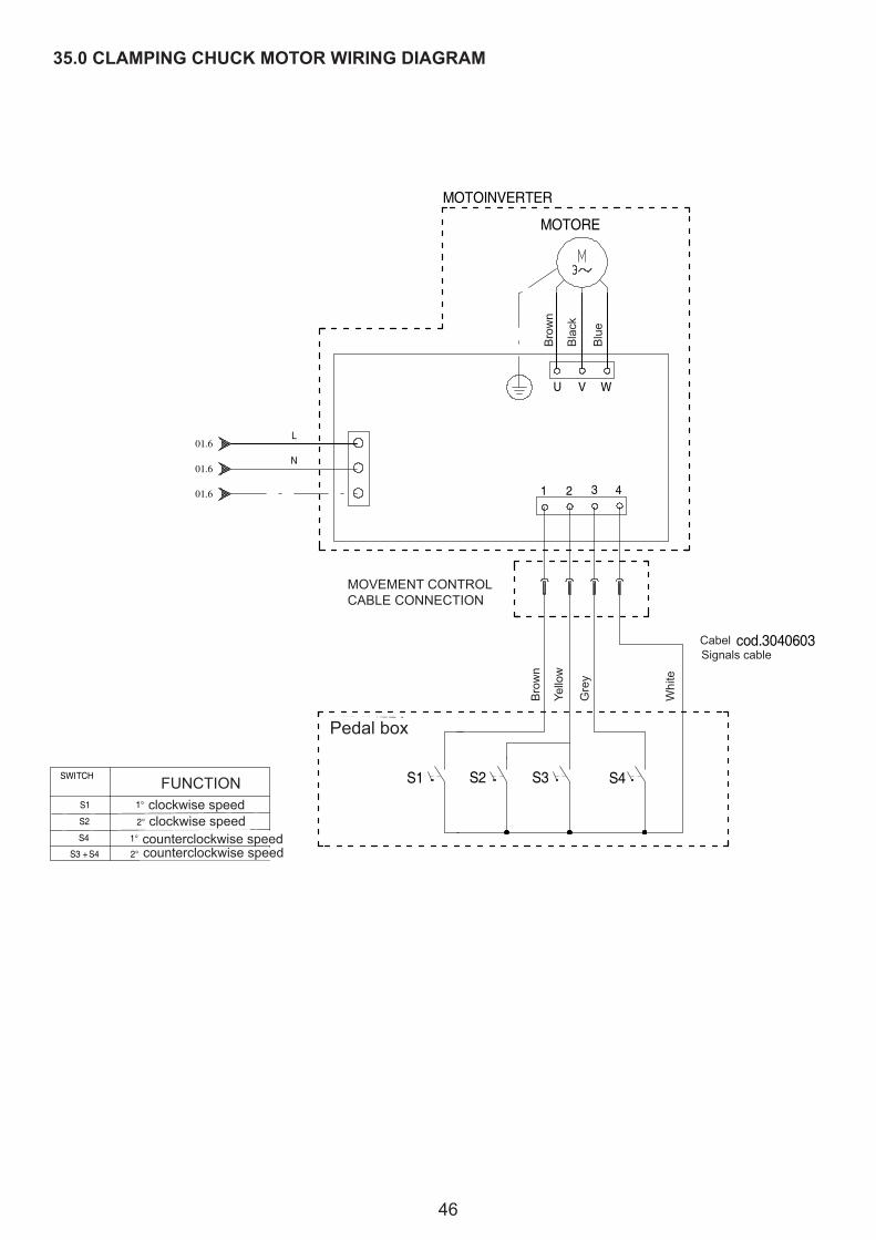
46
35.0 CLAMPING CHUCK MOTOR WIRING DIAGRAM
1 2 3 4
MOTORE
U V W
COLLEGAMENTO CAVO GESTIONE MOVIMENTI
1° VELOCITA' ORARIA
BIA
NC
O
GR
IGIO
GIA
LLO
MA
RR
ON
E
MOTOINVERTER
S1 S3 S4
PEDALIERA
MA
RR
ON
E
NER
O
BLU
FUNZIONE
S1
S2
S4
S2
S3 + S4
Cavo cod.3040603
SCHEMA COLLEGAMENTO MOTORE MANDRINO
2° VELOCITA' ORARIA
1° VELOCITA' ANTI-ORARIA
2° VELOCITA' ANTI-ORARIA
SWITCHCOMANDO
Cavo Segnali
N
L
01.6
01.6
01.6
Bro
wn
Bla
ck
Blu
eMOVEMENTCONTROLCABLECONNECTION
Yellow
Bro
wn
Grey
White
Pedalbox
CabelSignals cable
FUNCTIONclockwise speedclockwise speed
counterclockwise speedcounterclockwise speed
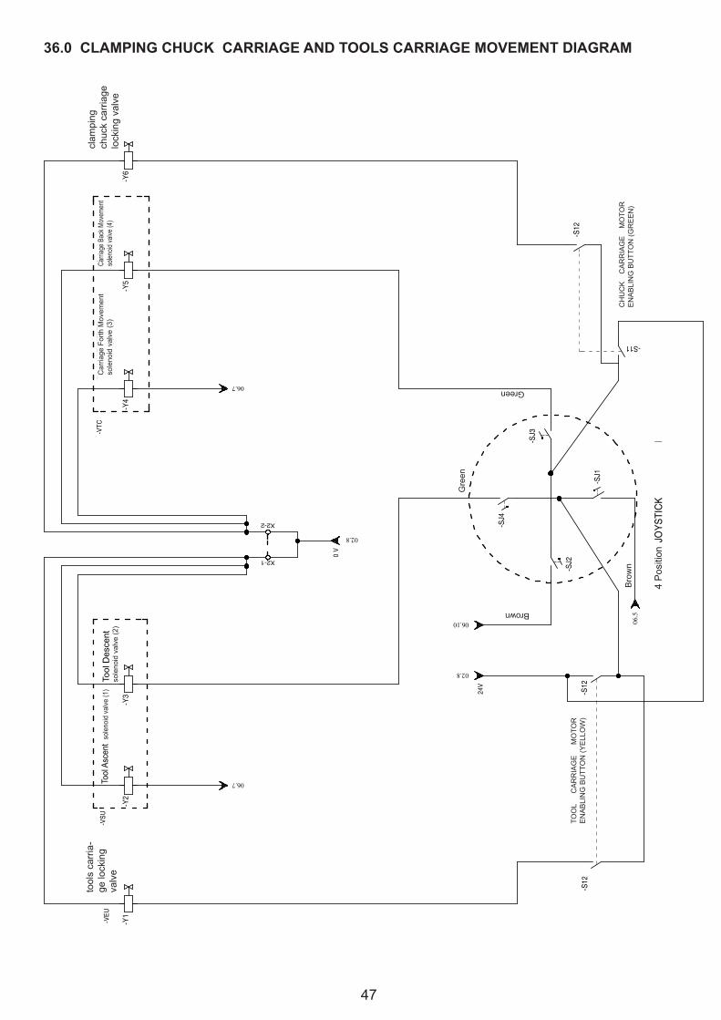
47
36.0 CLAMPING CHUCK CARRIAGE AND TOOLS CARRIAGE MOVEMENT DIAGRAM
JOYS
TIC
K 4
POS
IZIO
NI
PULS
ANTE
VER
DE
ABIL
ITA
ZIO
NE
CA
RR
ELLO
M
AND
RIN
O
PULS
ANTE
GIA
LLO
ABIL
ITAZ
ION
E C
ARR
ELLO
UTE
NS
ILE
Mar
rone
Marrone
Verde
Ver
de
0 V
EV. S
TRAN
GO
LA
UTE
NSI
LE
EV. S
ALIT
A U
TEN
SILE
(1)
EV. D
ISC
ESA
UTE
NSI
LE (2
)EV
. STR
ANG
OLA
M
AND
RIN
O
EV. A
RR
ETR
AMEN
TO
MAN
DR
INO
(4)
EV. A
VAN
ZAM
ENTO
M
AND
RIN
O (3
)
24V
-VEU
-VSU
-VTC
-VEC
-Y1
-S12
-Y2
06.7
-Y3 -S
12
02.8
06.10 06.5
-SJ2X2-1
02.8
X2-2 -SJ4
-SJ1
-SJ3
-Y4
06.7
-S11
-Y5
-S12
-Y6
CHUCKCARRIAGEMOTO
R
ENABLINGBUTT
ON(G
REEN)
4Position
Bro
wn
Brown
Green
Green
TOOL
CARRIAGE
MOTO
R
ENABLINGBUTT
ON(Y
ELLOW)
CarriageBa
ckMovem
ent
solen
oidva
lve(4)
CarriageForthMovem
ent
solenoidvalve(3)
ToolAscentsolenoidvalve(1)
Tool
Des
cent
solenoidvalve(2)
clam
ping
ch
uck
carr
iage
lockingvalve
tool
s ca
rria
-ge
lock
ing
valve

48
37.0 PNEUMATIC DIAGRAMS
Filtr
o R
egol
ator
e
Sorg
ente
Rub
inet
to
Ingr
esso
aria
Lubr
ifica
tore
Dis
tribu
toreCilin
dro
Pres
s Ar
m
Valv
ola
Pres
s Ar
m
Fine
cors
a sc
aric
oPr
ess
Arm
Cilin
dro
Ove
rcor
sa S
tallo
nato
ri
Valv
ola
Ove
rcor
sa S
tallo
nato
ri
Cilin
dro
dopp
io s
tadi
o m
ovim
ento
ung
hia
A B C
F
8-10
bar
- VP
- PA
- CP
- CO
- CU
8-14
bar
-VO
Abilit
azio
ne
mov
imen
to u
nghi
a
Valv
ola
mov
imen
to
ungh
ia
-VA-VM
- VN
RVa
lvol
a di
Non
Rito
rno
Valv
ola
sing
olo
cilin
dro
- VS
Cilin
dro
brac
cio
uten
sile
sm
onta
ggio
Valv
ola
smon
tagg
io
- CTS
- VTS
D
XTo
ol
movem
ent
valve
Cyl
inde
r for
bea
d breakerdisksover-
runmovem
ent
Valveforb
ead
brea
ker d
isksover-
runmovem
ent
BP1Pluscylinder
BP1Plusvalve
BP1Plusend
of s
troke
rele
ase
valve
Dis
tribu
tor
Airsupply
Airinletvalve
Lubr
icat
or
Filterregulator
Dem
ountingvalve
Dem
ount
ing
cylin
der
Dou
ble
stag
e cy
linde
r for
XToolmovem
ent
cylindervalve
XTo
ol
movem
ent
enablingvalve
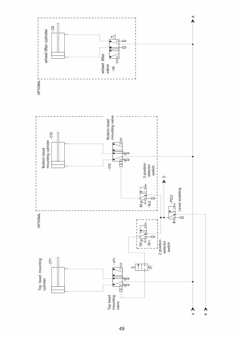
49
Con
sens
o Le
va
A B
Sele
ttore
2 po
sizi
oni
SXD
X
Cilin
dro
mon
tagg
ioTa
llone
Sup
erio
reC
ilindr
o m
onta
ggio
Tallo
ne In
ferio
re
Valv
ola
mon
tagg
ioTa
llone
Sup
erio
re
Valv
ola
mon
tagg
ioTa
llone
Infe
riore
A
- CT2
- CT1
- VT2
- VT1
- PC
L2
- SL1
- SL2
D
OPT
ION
ALC
ilindr
o So
lleva
tore
Valv
ola
So
lleva
tore
- VS
- CS
OPT
ION
AL
Sele
ttore
3 po
sizi
oni
whe
el li
fter c
ylin
der
whe
el l
ifter
valve
Bot
tom
bea
d m
ount
ing
cylin
der B
otto
m b
ead
mountingvalve
3 po
sitio
n se
lect
or
switc
h
2 po
sitio
n se
lect
or
switc
h
Leverenabling
Top
bead
m
ount
ing
valve
Top
bead
mou
ntin
g cy
linde
r
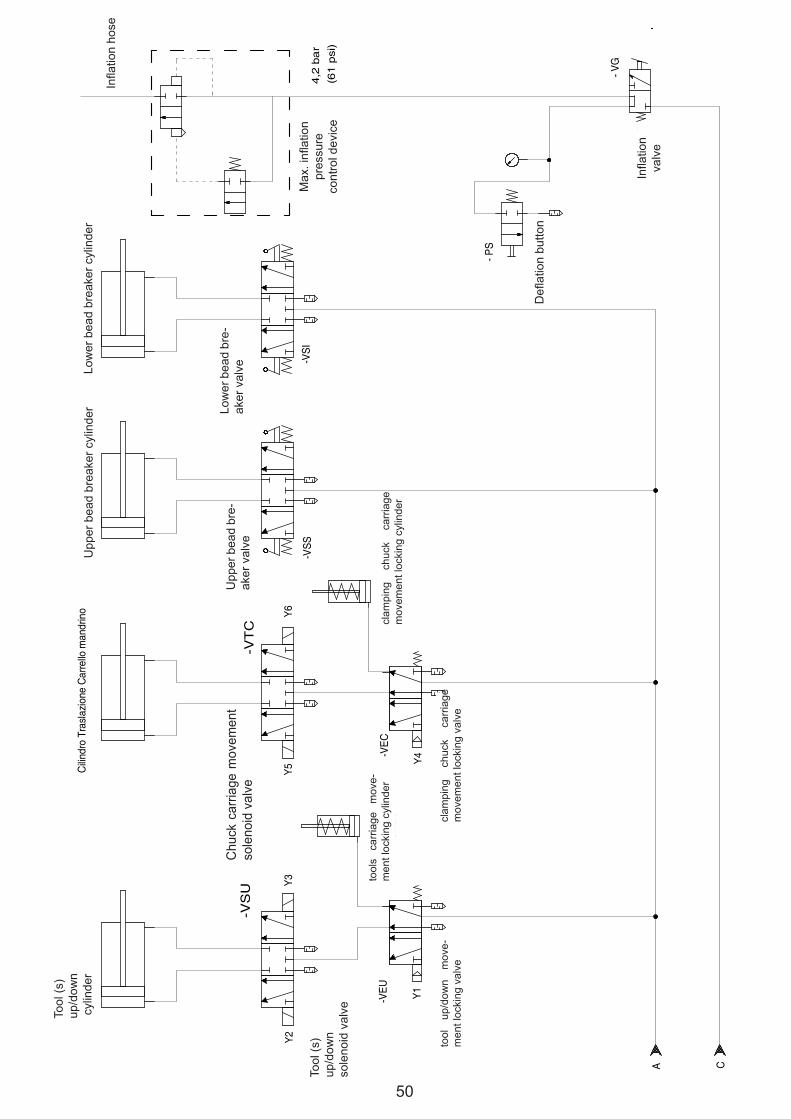
50
Valv
ola
di
gonf
iagg
io
Tubo
di
gonf
iagg
io
4,2
ba
r (6
1 p
si)
Dis
posi
tivo
cont
rollo
pr
essi
one
mas
sim
adi
gon
fiagg
io
Puls
ante
di
sgon
fiagg
io
C
- PS
- VG
A
Cilin
dro
Salit
a/D
isce
sa U
tens
ileC
ilindr
o Tr
asla
zion
e C
arre
llo m
andr
ino
-VEU
-VEC
Y1
Y2Y3
Y4
Y5Y6
Elet
trova
lvol
a Sa
lita/
Dis
cesa
Ute
nsile
Elet
trova
lvol
a S
trang
ola
Salit
a/D
isce
sa U
tens
ile
Elet
trova
lvol
a Tr
asla
zion
e ca
rrello
man
drin
o
Elet
trova
lvol
a s
trang
ola
Tras
lazi
one
carre
llo m
andr
ino
Cilin
dro
Stal
lona
tore
Sup
erio
reC
ilindr
o St
allo
nato
re In
ferio
re
Valv
ola
Stal
lona
tore
Sup
.
Valv
ola
Stal
lona
tore
Inf.
-VSS
-VSI
Cilin
dro
Stra
ngol
a tra
slaz
ione
car
rello
ut
ensi
le
Cilin
dro
Stra
ngol
a tra
slaz
ione
car
rello
m
andr
ino
-VS
U-V
TC
Inflation
valve
Deflationbutton
Max.inflation
pres
sure
controldevice
Inflationhose
Low
er b
ead
brea
ker c
ylin
der
Low
er b
ead
bre-
akervalve
Upperbeadbreakercylinder
Upperbeadbre-
akervalve
Chuckcarriagem
ovem
ent
solenoidvalve
Tool(s)
up/d
own
cyl
inde
r
Tool(s)
up/d
own
solenoidvalve
clam
ping
ch
uck
carr
iage
movem
entlockingcylinder
clam
ping
ch
uck
carr
iage
movem
entlockingvalve
tools
carriagemove-
men
t loc
king
cyl
inde
r
toolup/dow
nmove-
mentlockingvalve

51
38.0 SERVICE REPORTS
All the operations made on the machine in the course of time must be reported herebelow so as to have anupdated situation of the efficiency of the machine.The user must carry out both cleaning and greasing operations according to the instructions given in thismanual.Any operation concerning the replacement of parts is strictly reserved to authorized and trained staff.
Date Signature
Intervention
Replacements
Notes
Date Signature
Intervention
Replacements
Notes
Date Signature
Intervention
Replacements
Notes

52
Date Signature
Intervention
Replacements
Notes
Date Signature
Intervention
Replacements
Notes
Date Signature
Intervention
Replacements
Notes
Date Signature
Intervention
Replacements
Notes

53
Date Signature
Intervention
Replacements
Notes
Date Signature
Intervention
Replacements
Notes
Date Signature
Intervention
Replacements
Notes
Date Signature
Intervention
Replacements
Notes