atiou l technical - nasa · 2013-08-31 · the university of alabama in huntsville p. 0. box 1247...
TRANSCRIPT

A STRUCTURED MICROPROGRAM SETFOR THE SUMC COMPUTER
TO EMULATE THE IBM SYSTEM/360MODEL 50
by
CESAR R. GIMENEZ
(NASA-CR-12,582) A STRUCTURPD ICBOPROGRAM N75-17125
SET FOR THE SUMC COMPUTER TO EMULATE THE Id&
SYSTEM/36 , MODEL 5, aO.S. Thesis - Ala
Univ. (Sperry Rand Corp.) 163 p HC UnclasCSCL 0)9B G3/61 u9919
A THESIS
Submitted in partial fulfillment of the requirementsfor the degree of Master of Science in Engineering in
The Department of Electrical Engineering
of
The Graduate School
of
The University of Alabama in Huntsville
Huntsville, Alabama
1975
'ATIOu" L TECHNICAL,-I ,-,ON SERVICE ."INFORMA -e I commerce
US D*P'V17, v A. 22151
https://ntrs.nasa.gov/search.jsp?R=19750009053 2018-07-13T19:58:35+00:00Z

THE UNIVERSITY OF ALABAMA IN HUNTSVILLEP. 0. Box 1247
Huntsville, Alabama 35807
THESIS APPROVAL FORM
Name of Candidate C. R. Gimenez
Major Subject Electrical Engineering
Title of Thesis A Structured Microprogram Set for the SUMC
Computer to Emulate the IBM System/360 Model 50
Approved by:
Thesis Committee:Chairman Date
Date Date
Date Date
Department Chairman Date
Dean of School Date
Dean of Graduate Studies Dateand Research
ii

ABSTRACT
The thesis consists of an explanation of the similarities between
regular and structured microprogramming; an explanation of machine
branching architecture (particularly in the SUMC computer) required for
ease of structured microprogram implementation; the implementation of a
structured microprogram set in the SUMC to emulate the IBM System/360;
and finally a comparison of the structured set with a nonstructured set
previously written for the SUMC.
iii

ACKNOWLEDGMENTS
The author wishes to thank Professor Charles A. Halijak; without
his kind assistance this thesis would not have been published. The author
wishes to acknowledge: Robert Asquith, of MSFC, who designed the SUMC,
and Charles A. Williams, who collaborated with the author in the design
and checkout of the original SUMC microcode set.
The author is grateful for the financial assistance for his under-
graduate and graduate education provided by persons or institutions which
follow: Cesar U. and Nora Gimenez (parents), Stetson University, U.S. Office
of Education, Diocese of South Florida, Chrysler Corporation, Pratt and
Whitney Aircraft, and Sperry Rand.
iv

BIOGRAPHICAL SKETCH
Cesar Raul Gimenez, P.E. was born in . In
1960 he moved to Miami, Florida, where he completed his secondary
education. He holds a Bachelor in Electrical Engineering from Georgia
Tech (1967). He has designed data acquisition, supervisory control,
video, and computer systems. He is a registered Professional Engineer
in Alabama and Florida.
v

PATENT NOTICE
The author signed a standard patent agreement with his employer,
who, in turn, is contractually obligated to inform the Government of,
and surrender patent rights to, all new technology developed under
contract. Since this thesis proceeded from work on such a contract,
material herein is potentially patentable by the Government.
vi

DEDICATION
To Linda, Michael, and Teri.
vii
CONTENTS
Chapter Page
I INTRODUCTION
1.1 Scope . . . . . . . . . . . . . . .. . . . . 11.2 Background of Thesis . . . . . . . . . . . . . . . . . 11.3 Objectives . . . . . . . . . . . . . . . . . . . . . . 3
II MICROPROGRAMMING
2.1 The Microprogrammable Computer . . . . . . . . . . . . 52.2 Formal Definitions of Regular Microprograms . . . . 62.3 Regular Microprogram Meaning . . . . .. ..... 72.4 Practical Aspects of Regular Microprogramming . .. 82.5 Structured Microprogramming . . . . . . ... . 8
III STRUCTURED MICROPROGRAMMING BRANCHING ARCHITECTURE
3.1 Machine Dependence . . . . . . . . . . . . . . . . . . 113.2 Ease of Implementation . . . . . . . . . . . . . . 11
IV SPACE ULTRARELIABLE MODULAR COMPUTER (SUMC)
4.1 General Description. . . . . . . . . . . . . . . . 314.2 System Organization and Data Flow .... . . . . . . 354.3 Functional Description . . . . ......... . 374.4 Computer Control . . . . . . . . . . . . . . . . 464.5 Timing . . . . . . . . . . .. . . . 49
V SUMC BRANCHING ARCHITECTURE
5.1 Sequence Control Unit . . . . . . . . . . . . . . . . 525.2 SUMC Conditional Checks . . . . . . . . . 525.3 SUMC Structured Microprogram Primitives . . . . . . . 555.4 Subroutines . . . . . . . ... . . . . . . . . . . . . 66
VI SUMC BB MICROCODE IMPLEMENTATION
6.1 Emulation . . . . . . ........... . . . 706.2 IBM System/360 Instruction Formats . . . . . . . . . . 706.3 Structured Microprograms ........... . . . . 70
viii

CONTENTS(Concluded)
Chapter Page
VII COMPARISON
7.1 Conclusion . ....... . ........ . . . . . 1367.2 Further Research . ............... . . . 137
REFERENCES . . . . . . ........ . . . . . . . . . . . . 138
APPENDICES
A Notation ................... 140B Flowchart Conventions . ....... . . . . . . .... 141C SPM Mask Registers . ........... . . . . . . 147D External Interrupts . .................. . 148
ix

LIST OF TABLES
Table Page
3.1 Successor Commands for Machine X . . . . . . . . . . . . . . 12
3.2 Successor Commands for Machine Y . . . . . . . . . . . . . . 19
3.3 Successor Commands for Machine Z . . . . . . . . . . . . . . 25
4.1 SUMC Control Memory Word Format ........... . . . 47
5.1 Successor Commands for SUMC BB . . . .......... . . 55

LIST OF FIGURES
Figure Page
2.1 Microprogrammed Computer Model . ............ . . 6
3.1 Concatenation Microflowchart for Machine X . . . ....... 13
3.2 Concatenation Macroflowchart for Machine X .. . . ..... 14
3.3 Decision Microflowchart for Machine X . . . . . . . . . .. 15
3.4 Decision Macroflowchart for Machine X . . . . . . . . . . . 16
3,5 Iteration Microflowchart for Machine X . . . . . . . . . 17
3.6 Iteration Macroflowchart for Machine X . . . . . . . . . . . 18
3.7 Concatenation Microflowchart for Machine Y . . . . . . . . 19
3.8 Concatenation Macroflowchart for Machine Y . . . . . . . . . 20
3.9 Decision Microflowchart for Machine Y . . . . . . . . 21
3.10 Decision Macroflowchart for Machine Y . . . . . . .... . 22
3.11 Iteration Microflowchart for Machine Y ......... . 23
3.12 Iteration Macroflowchart for Machine Y . . . . . . . . . 24
3.13 Concatenation Microflowchart for Machine Z . . . . .. . .... 25
3.14 Concatenation Macroflowchart for Machine Z ..... ...... 26
3.15 Decision Microflowchart for Machine Z . ....... . . 27
3.16 Decision Macroflowchart for Machine Z . ....... . . 28
3.17 Iteration Microflowchart for Machine Z . . . . .. . . . .. 29
3.18 Iteration Macroflowchart for Machine Z . . . . . . . .. . . 30
4.1 Simplified SUMC Block Diagram . . . . . . .... . . . 32
4.2 Sample Scratch Pad Memory Map . ......... . . . . 33
xi

LIST OF FIGURES(Continued)
Figure Page
4.3 SUMC BB Block Diagram . . . . . .. . . . . . . . ....... 36
4.4 Basic SUMC Timing Signals . . . . . . .. . . . . . ...... 50
5.1 SUMC Concatenation Microflowchart . . . . .. . . . .... . 56
5.2 SUMC Concatenation Macroflowchart . . . . .. . . . ...... 57
5.3 SUMC Decision Microflowcharts . . . . . .. . . . . ...... 58
5.4 SUMC Decision Macroflowcharts . . . . . .. . . . . ...... 60
5.5 SUMC Iteration Microflowcharts . . . . . .. . . . ...... 62
5.6 SUMC Iteration Macroflowcharts . . . . .. . . . ...... 64
5.7 SUMC N-Iterative Loop . .............. . . .. 67
5.8 SUMC N+l-Iterative Loop . . . . . .. . . . . . . . ...... 68
5.9 SUMC Do Once Loop . ........... . . . .. . 69
RR FORMAT INSTRUCTIONS
6.1 Add Register (AR) Microprogram . . . . .. . . . . ...... 72
6.2 Add Logical Register (ALR) Microprogram .. . . ...... 73
6.3 And Register (NR) Microprogram . . . . .. . . . . ...... 74
6.4 Compare Register (CR) Microprogram ............ 74
6.5 Branch and Link Register (BALR) Microprogram .. . . . 75
6.6 Branch on Condition Register (BCR) Microprogram . . . . . . 76
6.7 Branch on Count Register (BCTR) Microprogram .. . . . 77
RX FORMAT INSTRUCTIONS
6.8 Add (A) Microprogram . .............. . . .. 78
6.9 Add Halfword (AH) Microprograms . . . . . .. . . ...... 79
6.10 Add Logical (AL) Microprogram . .......... . . .. 79
xii
LIST OF FIGURES(Continued)
Figure Page
6.11 And (N) Microprogram . . . . . . . . . . . . . ....... 80
6.12 Compare (C) Microprogram . . . . . . .. . . . . . ...... 80
6.13 Compare Halfword (CH) Microprogram . . . . . .. . . . . 81
6.14 Branch and Link (BAL) Microprogram . . . . . . . ..... 82
6.15 Branch on Condition (BC) Microprogram . . . . . . . .. . 83
6.16 Branch on Count (BCT) Microprogram . . . . . .. ..... 83
RS FORMAT INSTRUCTIONS
6.17 Branch on Index High (BXH) Microprogram . . . . . . . . . 84
6.18 Branch on Index Low or Equal (BXLE) Microprogram . . . .. 85
SI FORMAT INSTRUCTIONS
6.19 Test Under Mask (TM) Microprogram . . . . . . . . . ... 86
6.20 Move Immediate (MVI) Microprogram . . . . . . . . . 87
6.21 Test and Set (TS) Microprogram . . . . . . . . . . . . . . 88
6.22 And Immediate (NI) Microprogram . . . . . . . . . . . . 89
6.23 Compare Logical (CLI) Immediate Microprogram . . . . . . . 90
6.24 Or Immediate (01) Microprogram . .......... . . . 91
6.25 Exclusive Or Immediate (XI) Microprogram . . . . . . . . . 92
6.26 SI Format (SIF) Microprogram . . . . . . . . . . . . . .. 93
6.27 SI Format (SIF1) Microprogram .. . . . . . . . ..... 94
SS FORMAT INSTRUCTIONS
6.28 Move Microprograms (MVC, MVN, MVZ) . ........... 95
6.29 Translate and Test (TRT) Microprogram . . . . . . . . .. 96
6.30 TRTC Microprogram . ........ ....... ... .. 97
xiii

LIST OF FIGURES(Continued)
Figure Page
6.31 TRTD Microprogram . . . . .. . . . . . . . . . . . . . . 98
6.32 Translate (TR) Microprogram . . . . . .. . . . . . . . . . 99
6.33 TRC Microprogram ..... . ...... . . .. . .. 100
6.34 SS Format (SSF) Microprogram ........ . . . . . . . 101
6.35 SS Format (SSFA) Microprogram . . . . . .. . . . . . . . . 102
6.36 SS Format (SSF+06) Microprogram . . . . .. . . . . . ..... 103
6.37 SS Format (SSFB) Microprogram . . . . . .. . . . . . . . . 104
6.38 SS Format (SSFC) Microprogram . . . . . .. . . . . . ..... 105
HOUSEKEEPING MICROPROGRAMS
6.39 Fetch (FTCH) Microprogram . ........... . . . . . 106
6.40 NIO Microprogram .. . . . . . . . . . . . ..... .. 107
6.41 EXCP Microprogram . ........... . . . .. ... . . 108
6.42 RX Microprogram . . . . . . . . . . . .. . .. . .. 109
6.43 NRX Microprogram . . . . .. . . . . . . . . . . . . . . 110
6.44 ABERR Microprogram .. . . . . . . . . . . . . . . 111
6.45 WAIT Microprogram ............ . . .. . . . 112
6.46 10 Microprogram . ............ ..... . ... 113
6.47 Load Program Status Word (LPSW) Microprogram . . ..... 114
6.48 LPS Microprogram ................... .. . 115
6.49 LPSA Microprogram . . . . ........ .. ......... . . . . . . . 116
6.50 LPSB, LPSC, LPSD Microprograms. .... . . . . . . .... 117
6.51 Overflow (OF) Microprograms . . . . . . . . .. . . . .. 118
6.52 OFS Microprogram . ....... ......... . .. . 119
6.53 OFSA Microprogram ............. . . . .. . . . . 120
xiv

LIST OF FIGURES(Concluded)
Figure Page
6.54 OFSB Microprogram ... . . . . . . ........ . . . . 121
6.55 Interrupt (INT) Microprogram . . . . . . . . . . . . . .. 122
6.56 INTEG12 Microprogram . . . . . . ............ . . 123
6.57 INTL8 Microprogram . ........ . . . .. . . . . 124
6.58 INTO, INTI, INT2, INT3 Microprograms. . ...... .. 125
6.59 INT23 Microprogram . . .... . . . . . . . ... . 126
6.60 INT4, INT5, INT6, INT7, INTF Microprograms .. ..... . 127
6.61 INT8 Microprogram . ......... ..... ...... 128
6.62 INT9 Microprogram . . . ................ . . . 129
6.63 INT10O Microprogram . ... ............... . 130
6.64 INT11 Microprogram .......... . .. . .. 131
6.65 INT12 Microprogram ............. o ....... 132
6.66 INT13 Microprogram . . . . o. . . ..... . . 133
6.67 INT14 Microprogram ..... ..... . .. . . . 134
6.68 INT15 Microprogram . .... . . . . . ... . . . . . . 135
xv

CHAPTER I
INTRODUCTION
1.1 Scope
This thesis assumes the reader is familiar with computer micro-
programming. It is intended to be a practical document that bridges the
gap between computer architecture and microprogramming. It is written
so that it appeals to those interested in computer architecture,
computer languages, and microprogramming.
A summary of the similarities between regular and structured
microprogramming is given in Chapter II. The mathematical foundations
for these are discussed in depth in the works of Dijkstra, Glushkov,
Ito, and Mills given in the References. The basic architectural struc-
tures needed to implement structured microprograms are explained in
Chapter III. The SUMC, a versatile aerospace microprogrammable computer
developed by NASA, is introduced in Chapter IV. Then, the basic struc-
tured primitives for the SUMC are developed in Chapter V. These are
used, throughout Chapter VI, to implement a subset of structured micro-
programs which emulate the IBM System/360. Finally, the structured
microprograms are compared with the corresponding nonstructured micro-
programs.
1.2 Background of Thesis
The Data System Laboratory, Marshall Space Flight Center (MSFC),
Huntsville, Alabama, is engaged in the development of a family of
2
computers known as Space Ultrareliable Modular Computers (SUMC). The
main guideline in the SUMC program is to develop a microprogrammable
computer family capable of emulating existing ground commercial com-
puters. As an employee of Sperry Rand, Huntsville, Alabama, supporting
Data Systems Lab (under contract No. NAS8-21812), the author was
assigned to write the microcode for the SUMC Breadboard (SUMC BB) used
in the emulation of an IBM System/360. The original microcode set [20]
occupied 1700 memory locations. Delivery delays of a similar micro-
code memory, to be used in the development of a SUMC input/output pro-
cessor (IOP), forced MSFC to require the SUMC microcode be rewritten
within a 1K (1024) memory module, to free the other SUMC BB memory
module for IOP use. The SUMC microcode was rewritten to fit within a
1K memory module. Careful attention was exercised so that not only
microcode size requirements were met, but also the resulting microcode
instruction set was faster in execution time.
The author has had an interest in regular expressions since 1968.
While reading articles on regular microprogramming, he noticed great
similarities between regular and structured programming. Structured
programming guidelines, have been issued by MSFC to be used in the
SUMC software development program. Similar guidelines, however, have
not been issued in the area of microprogramming. This thesis explores
the use of structured microprogramming in the SUMC Breadboard. This
objective was not brought about from a mere desire to illustrate
structured microprogramming implementation, but rather to illustrate
structured microprogramming implementation under realistic design
constraints. Most of the current literature on structured programming

3
concepts deals with high level language implementation. Since high
level languages are, by design, machine independent, the application
of structured programming techniques to them is rather straightforward.
On the other hand, microprogramming is machine and real time dependent.
Thus, the application of structured programming techniques in this
area is more difficult. But most important, all design is subject to
unpredictable restrictions (such as those caused by the delivery delay
discussed above). Thus, the author's approach was to rewrite the
microcode used in the SUMC BB emulation of the IBM System/360, with
similar constraints. He purposely, preserved the sequence of events
within the microprograms whenever possible. In this manner (with the
algorithms as a fixed parameter), the two microcode sets could be more
easily compared. At the same time, he was insured that the structured
microprogram set was a valid one. That is, once this set is assembled
into machine language and loaded into memory, it will successfully
emulate an IBM System/360 in the problem state.
1.3 Objectives of Thesis
The objectives of this thesis are as follow:
Objective 1. To point out the similarities between regular and
structured microprogramming. This objective was fulfilled.
Objective 2. To study the branching architecture required for
ease of structured microprogramming implementation. This objective
was also fulfilled.
Objective 3. To write a complete structured microcode set for
the SUMC BB for the emulation of an IBM System/360.

This objective was partially but adequately fulfilled. Rather
than rewritting the complete microcode set, the author selected micro-
programs subsets which exemplify the implementation techniques and
point out the main differences between the sets. By doing this, he
eliminated many repetitious sections from the thesis.
Objective 4. To compare the size, speed, and ease of implementa-
tion of the structured and nonstructured microprogram sets. This
objective was fulfilled.

5
CHAPTER II
MICROPROGRAMMING
2.1 The Microprogrammable Computer
Consider a simplified computer model consisting of two blocks: an
operational and a control automaton shown in Fig. 2.1. The output of
the operational automaton is the string of values of the logical condi-
tions (predicates) p1 ' P2' .. ' Pn. If the current state sj of the
automaton belongs to S, then the logical condition is taken to be
satisfied (pj = 1). Otherwise, the condition is not satisfied (pj = 0).
The output signals (microoperations) of the control automaton
(m, m2, ... , 'mn) are identified with certain transformations of the
set of states of the automaton. That is, m: S - S. Note that the
output of the control automaton corresponds to an input string of the
operational automaton.
A microprogrammable computer is a structure:
C= {S,I,O,MP
of partial functions for which there exist: The set of states, S; the
set of input sequences, I; the set of output sequences, 0; the set of
microprograms, M; and the set of predicates, P. The input function I
is related to S by a mapping of I into S. Thus, the input function,
I: I -* S. Similarly, for the output function, 0: S + 0; for the
microprogram set, M: S S; and for the predicate set, P: S + (0,1).

6
Operational (ml m2, ..."' mn) ControlAutomaton ( Automaton
(P ' P2' "" Pn)
Input Output
Figure 2.1. Microprogrammed Computer Model
2.2 Formal Definition of Regular Microprograms
A class of regular microprograms [8] can be defined recursively as
follows:
1. Individual microoperations (e, mi, m2, ... , mn) are
regular microprograms. The NO-OPERATION microoperation is e.
2. If x and y are regular microprograms, then regular micro-
programs are formed by the following rules:
a. Concatenation
x * y ; meaning x followed by y
b. Decision expressions
< x v y > ; meaning p * x v ~ * yp
c. Iteration
[ x ] ; meaning while p do xp

7
3. Where p is a predicate term as defined below:
a. Individual predicates (T, F, pi,' 2 ' ..." pn) are
predicate terms.
b. If x is a regular microprogram and p is a predicate,
then x * p is a predicate term.
c. If p and q are predicate terms, then p v q, p A q,
P are predicate terms.
2.3 Regular Microprogram Meaning
A regular microprogram has meaning only when an interpretation is
given. An interpretation for regular microprograms is specified by a
computer C = {S,I,0,M,P} on which a regular microprogram is represented.
For any state s of S, regular microprograms will be given to the
following meaning:
1. e(s) = s
2. x * y(s) = y(x(s))
3. < x v y >(s) = if p(s) then x(s), else y(s)
p
4. [ x ](s) = while p(s) do x(s)p
5. T(s) = true; F(s) = false
6. x - p(s) = p(x(s))
7. (p v q)(s) = if p(s) then true, else q(s)
8. (p A q)(s) = if p(s) then q(s), else true
9. (p - q)(s) = if p(s) then q(s), else false
10. (5)(s) = if p(s) then false, else true
11. p(s) . q(s) = q(s) * p(s) = p(q(s)) = q(p(s))

8
2.4 Practical Aspects of Regular Microprogramming
But why should one be concerned with regular microprograms? As
it is clearly shown in the works of Glushkov [3, 4]: "Any microprogram
can be represented in regular form. There exists an algorithm for
transformation of arbitrary microprograms written in ordinary form into
regular form". Ito [8] has shown that any microprogram can be written
in an ordinary flowchart or an automaton diagram, and that this flow-
chart or automaton diagram can be represented by a linear system of
equations of regular microprograms. Furthermore, any linear system of
equations of regular microprograms can be solved and its solutions are
in the class of regular microprograms.
2.5 Structured Microprogramming
Structured programming is currently receiving a great deal of
attention. The theorems providing the mathematical foundations of
structured programming given by Mills [14] are: The structure Theorem
("Any flowchartable program logic can be represented by the expansions
of as few as three types of structures"), the TOP-DOWN Corollary
("structured programs can be written or read top-down"), the
Correctness Theorem (under certain conditions, "a program can be proved
correct by a tour of its program tree"), and the Expansion Theorem
which gives the rules for top-down decomposition. The three types of
control structures which are usually used as a basis for the control
structures of flowchartable programs are:
1. f then g
* f * * g ****** ***x*

9
2. If p then f, else g
Yes * * No• . * p *
* fS .**** . * **** . *
3. While p do f
* * Yes * * * * * ** * Yes****** p * .. .* f * .
* *****
* NO
Structured microprogramming is defined as the implementation of
microprograms utilizing only concatenation, decision expressions, and
iteration primitives.
It is obvious that the three structured microprogramming primitives
correspond to the expressions given under Rule 2 in the formal defini-
tion of regular microprograms. Note that f corresponds to x, and g
corresponds to y.
2a. Concatenation
x * y f then g

10
2b. Decision expressions
< x v y > If p then f, else gp
2c. Iteration Do while
[ x ] While p, do x
p
When implementating structured microprogramming (or programming
in general) it is common practice to implement the iteration primitive
[ x ] (while not p do x), instead of [ x ]. This is done because itP Pis easy to load some iteration counter with a positive value (1 < v < N)
prior to entering the iteration. The iteration count is decremented by
a fixed number (usually 1) with each pass through the iterative loop,
until the iteration count is made zero (or sometimes negative) prior to
exiting the primitive. Refer to Section 5.3. Note that either [ x ]p
or [ x ] can be used as a primitive without losing the validity of the
conclusions previously made. The iteration primitive when implemented
is always finite. That is, a finite number of passes are made prior to
exiting the iteration.

CHAPTER III
STRUCTURED MICROPROGRAMMING BRANCHING ARCHITECTURE
3.1 Machine Dependence
Microprogramming is machine dependent. Thus, the ease with which
one can implement structured microprograms in a given microprogrammable
computer is closely governed by the machines' branching architecture.
Implementation of the aforementioned control primitives is significantly
more difficult at the macro level because specific return addresses
must be saved within the macros.
3.2 Ease of Implementation
The relationship between branching architecture and ease of struc-
tured microprogramming implementation is best shown by example. In
the following pages three machines (X, Y, and Z) will be discussed.
A table summarizes the machine commands used in microinstruction
sequencing. Each control primitive is implemented for each machine
both at the micro and macro level. For each primitive, a microprogram
and a macroprogram are given. The programs are further illustrated by
the corresponding micro and macro flowcharts. The following abbrevia-
tions are used for the sequencer and alternate sequencer registers:
SEQ and ASEQ respectively. Two other utility registers LITERAL (LIT)
and TEMPORARY (T) are used.

12
TABLE 3.1
Successor Commands for Machine X
COMMAND NEST INSTRUCTION ADDRESS RETURN ADDRESS
STEP (SEQ) + 1SKIP (SEQ) + 2SAVE (SEQ) + 1 (SEQ) - (ASEQ)CALL (ASEQ) + 1 (SEQ) - (ASEQ)JUMP (ASEQ) + 1RETN (ASEQ) + 2WAIT (SEQ)
The successor commands for Machine X [16], are given in Table 3.1.
The default successor command is STEP. The machine has two pointers
into control memory, SEQ and ASEQo It has subroutine capabilities
provided by the CALL and RETN commands. Both true and false successors
can be specified in each instruction. Figures 3.1 through 3.6 further
illustrate the implementation of structured primitives given in the
text for Machine X.
At the micro level, the structured microprogram primitives can be
easily implemented. However, implementation of these primitives at the
macro level is more difficult because specific return addresses must be
inserted within the macros.
Primitive: f then g
Microprogramf, STEPg

13
* ENTRY
* f *
* STEP
* g *
Figure 3.1. Concatenation Microflowchart for Machine X
Primitive: f then g
Macroprogramfl' STEP
f2' STEP
fn STEP
G - 1=: ASEQ
JUMP
G1: g

14
* ENTRY *
*********
* fl **** * ****
FlSTEP
f2* f2 **********
. F2
* f, **********
. Fn
*********
* Gl-1 t (ASEQ) *
JUMP
* g *
G1
Figure 3.2 Concatenation Macroflowchart for Machine X
Primitive: If p then f, else g
MicroprogramIf p then SKIP, else STEP
G: g, SKIP
F: f, STEP

15
* ENTRY
STEP NO * * YES SKIP
* * * - -
S** *
* g * * f *
* 2 3
SKIP STEP
*** **
4
Figure 3.3. Decision Microflowchart for Machine X
Primitive: If p then f, else g
MacroprogramF1 - 1 =: ASEQ
If p then CALL, else STEP
G1 - 1 =: ASEQ
If (not p) then CALL, else STEP
F: f: fl
f2
fn-1
fn, RETN
G: g: 91
92
gms JUMP

16
* ENTRY *
* F - 1 (ASEQ) ** *1.........
STEP NO * * YES CALL
* * * ** ** 9
* G - 1 + (ASEQ) * * f *
* * *F 1
* *****
* p * * * * *****
2STEP YES
* * * * * *E * G *E *
E * ***** *****R * * *fn-1 *
* ***** *****
T Fn-1AK.K * ***** *****E * * 9m * * fn *N* ***** *****
* * Gm FnJUMP* * * * * * * * * * * * * * * RETN
* *
3
Figure 3.4. Decision Macroflowchart for Machine X

17
Primitive: While 0, do f
MicroprogramROM - 1 =: ASEQ
ROM: If (not p) then STEP, else SKIP
f, JUMP
g
* ENTRY
* ROM-1 - (ASEQ) *
* ROM-1
* *
* * NO STEP * * * * * JUMP• p *---.-* f *.....
* * *****
*ROM ROM + 1
YES ** SKIP
* g *
ROM + 2
Figure 3o5. Iteration Microflowchart for Machine X
18
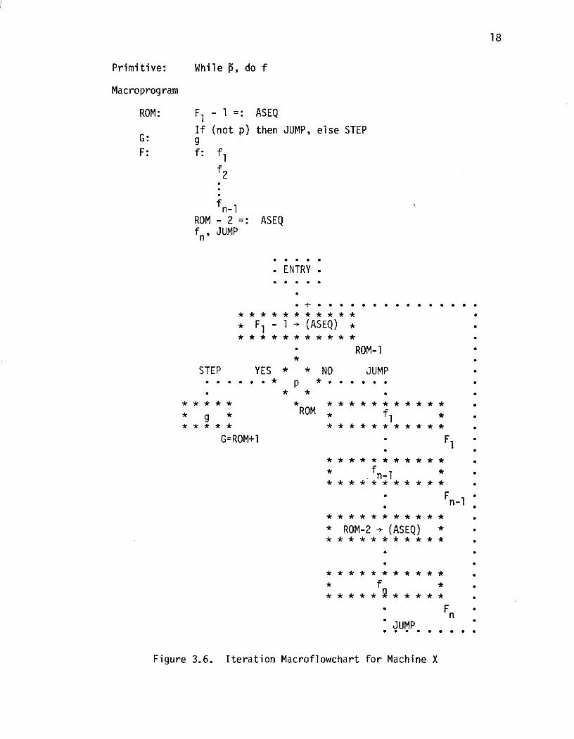
Primitive: While 5, do f
Macroprogram
ROM: F1 - 1 =: ASEQ
If (not p) then JUMP, else STEPG: gF: f: fl
f2
n-lROM - 2 =: ASEQfn, JUMP
. ENTRY .
-* * * * * * * * * * *
* F1 - 1 (ASEQ) .
* ROM-1
STEP YES * * NO JUMP
* * * * *
S* * ** * *** *** ** ** *
* g . ROM . fl ** * * * * * * * * * * * * * * * *
G=ROM+ * F1
* * * * ** * * * * * *
* fn-I *
* Fn-l
* ROM-2 - (ASEQ) ** ** * * ** ** * * *
* * * * * * * * * **
* f *S** * * ****
* F *nJUMP
Figure 3.6. Iteration Macroflowchart for Machine X

19
TABLE 3.2
Successor Commands for Machine Y
COMMAND NEXT INSTRUCTION ADDRESS RETURN ADDRESS
STEP (SEQ)+lSKIP (SEQ)+2SAVE (SEQ)+l (SEQ)+1 + (ASEQ)CALL (LIT) (SEQ)+1 + (ASEQ)JA (ASEQ)JL (LIT)JT (T)
The successor commands for Machine Y [17] are given in Table 3.2.
The machine has four pointers into control memory: SEQ, ASEQ, LIT,
and T. The STEP, SKIP, SAVE, and CALL commands are similar to those
of Machine X. Only one successor can be specified in each microinstruc-
tion. The default successor is always STEP. Machine Y has three JUMP
commands. At the macro level, the existence of multiple JUMP commands
simplifies returns from the function f and facilitates modular decomposi-
tion of the microcode. However, specific return addresses must still be
inserted within the macros.
Primitive: f then g
Microprogramf, STEPg
* ENTRY *
* f *
SSTEP
* g *
Figure 3°7. Concatenation Microflowchart for Machine Y

20
Primitive: f then g
Macroprogramfl' STEP
, STEP
G1 =: ASEQ, JA
G1 g
* ENTRY *
*******
* f *
. F1
:STEP
* f *
. Fn
:STEP
* Gi (ASEQ) *
JA
* g *
Figure 3.8. Concatenation Macrofowchart for Machine Y
Figure 3.8. Concatenation Macroflowchart for Machine Y

21
Primitive: If p then f, else g
MicroprogramIf p then SKIP, else STEPg, SKIPf, STEP
* ENTRY
STEP NO * * YES SKIP
* 1* p
* g f 1
* 2 . 3* SKIP STEP
* * . * * * . * *
4
Figure 3.9. Decision Microflowchart for Machine Y
Primitive: If p then f, else g
MacroprogramF1 =: LITERAL
If p then CALL, else STEPG1 =: LITERAL
If (not p) then CALL, else STEPF: f: fl
n-1F , JA
G: g: gl1
gm, JA

22
* ENTRY "
Fl (LIT)
CALL YES * * NO STEP
** * * * * ** * * * * * * * ****
* f * * G * (LIT) *
SF 1 *F 1 STEP YES * * NO CALL
* * * * * * * * * * * . . * p * . . . . . .
* * * * * ************ * *2
. * g1 *** ** *
* * * * * * * * * * * *
F V * *EF n-1 *V
E *****R********** *R
* (ASEQ)+1 (ASEQ) * :*********** T *****
*A * 9gm **K*E G*********** *E . G
* fn * N
F* n ** JA . JA *
*****
* *
3
Figure 3.10. Decision Macroflowchart for Machine Y

23
Primitive: While , do f
MicroprogramROM =: ASEQ
ROM: If (not p) STEP, else SKIPf, JAg
* ENTRY
* ROM (ASEQ) *
* ROM-1
* STEP NO * * YES SKIP
* . * * -.* * *
S ** ROM* * f * * g *S ***** **g **
* * ROM+l ROM+2
. . . JA
Figure 3.11. Iteration Microflowchart for Machine Y
Primitive: While , do f
MacroprogramF1 =: ASEQ, STEP
ROM =: LITROM: If (not p) then JA, else STEP
Fl: f: fl
n JL

24
* ENTRY
* F1 (ASEQ) *** *******
. STEP
* ROM - (LIT) *
* ROM-1
. *
S* * STE
* ***** * *****
* fl * ROM g* ***** *****
* * F1 ROM+l
. *****
* *
* *****
* fn *
F* . * n
* * * * * * *JL
Figure 3.12. Iteration Macroflowchart for Machine Y
The successor commands for Machine Z are given to Table 3.3. At
the micro level, the implementation of structured primitives is identi-
cal to that of Machine Y. However, at the macro level, the implementa-
tion of the decision primitive is considerably easier since this
successor set allows for multiple return addresses to be specified

25
outside of the macro instruction blocks. Thus, substantial improve-
ments in microprogramming efficiency and a reduction in control memory
size are possible with Machine Z.
Microprogrammable machines are not easy to program structuredly
unless the branching architecture capabilities provide for easy
implementation of the structured primitives. In particular, a successor
set consisting of STEP, SKIP, SAVE, two CALL, and two JUMP commands,
should be sufficient to implement structured microprograms with ease.
TABLE 3.3
Successor Commands for Machine Z
COMMAND NEXT INSTRUCTION ADDRESS RETURN ADDRESS
STEP (SEQ)+lSKIP (SEQ)+2SAVE (SEQ)+1 (SEQ)+1 + (ASEQ)CALLA (ASEQ) (SEQ)+1 + (ASEQ)CALL (LIT) (SEQ)+l -P (ASEQ)JA (ASEQ)JL (LIT)
Primitive: f then g
Microprogramf, STEP
* ENTRY *
* f *
* STEP
* g *
Figure 3.13. Concatenation Microflowchart for Machine Z

26
Primitive: f then g
Macroprogram
F1 fl STEP
fn, STEP
G1 =: ASEQ, JA
G1: g
* ENTRY *
********
S fl *
* STEP F1
* STEP
* f_ n
*STEP Fn
* Gl (ASEQ) *
* JA
* g *
GFigure 3.14. Concatenation
Figure 3.14. Concatenation Macroflowchart for Machine Z

27
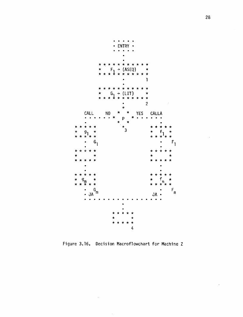
Primitive: If p then f, else g
MicroprogramIf p then SKIP, else STEP
G: g, SKIPF: f, STEP
* ENTRY
NO * * YES
* * *** p * * ***
S * **
S 2 * 3
SKIP STEP
4
Figure 3.15. Decision Microflowchart for Machine Z
Primitive: If p then f, else g
MacroprogramF1 =: ASEQ
G1 =: LIT
If p then CALLA, else CALL
F1: f: fl
fn, JA
G1: g: 91
gm' JA
28
* ENTRY *
• * * * * * * * * * *
* F (ASEQ) *• ** *******
* 1
* G + (LIT) *
* 2*
CALL NO * * YES CALLA
* **** ** *****
* 9 * 3 * fS** * * * * *1
SG F1
• **** *****
* * * *
• **** *****
• **** *****
* , * * fn *• **** *****
* G * F*JAm JA * n
*****
* *
4
Figure 3.16. Decision Macroflowchart for Machine Z

29
Primitive: While 1, do f
MacroprogramROM =: ASEQ
ROM: If (not p) then STEP, else SKIPF: f, JAG: g
* ENTRY *
* ROM - (ASEQ) *
* ROM-1
* * NO * * * * JA *p * . * f * *
* ROM F=ROM+1
* g *
G=ROM+2
Figure 3.17. Iteration Microflowchart for Machine Z
Primitive: While 1, do f
MacroprogramF1 =: ASEQ
ROM =: LIT
ROM: If (not p) then JA, else STEPG: g, STEP
F1: f: f.1
f , JLn

30
* ENTRY *
* 0 *
S FF + (ASEQ) *
. ROM-2
• ROM + (LIT) *
. ROM-1
* *NO JA
* *** 0
ROM *f. * * *
YES
* STEP *
* g * * *
G=ROM+1 •
f *.
n- n-l* Fn-1 "
*f *
'JL F n
Figure 3.18. Iteration Macroflowchart for Machine Z

31
CHAPTER IV
SPACE ULTRARELIABLE MODULAR COMPUTER (SUMC)
4.1 General Description
The simplified SUMC block diagram shown in Fig. 4.1 depicts SUMC's
logical construction. Six major logic blocks are shown and are briefly
described herein to provide the reader a better understanding of SUMC's
microprogrammed control. These logic blocks are the Main Memory Unit,
the Scratch Pad Memory, the Arithmetic Logic Unit, the Multiplexer
Register Unit, the Floating Point Unit, and the Control Unit.
The Main Memory Unit (MMU) is a 32 bit plated wire memory which
is used to store program instructions and data. The memory addressing
scheme allows access of up to 4 billion words.
Scratch Pad Memory (SPM) consists of sixty-four 32 bit registers.
Factors which determine SPM use and allocation are:
1. Instruction format and repertoire.
2. Memory addressing scheme.
3. I/0 and interrupt processing scheme.
Scratch Pad Memory register assignments for the 32 bit floating point
SUMC Breadboard are shown in Fig. 4.2.
The Arithmetic Logic Unit (ALU) consists of three multiplexers
and two parallel arithmetic units. Multiplexers are used to select
the data source(s) for the two arithmetic units which perform the
required logical or arithmetic operation.

32
FLOATINGPOINT UNIT
(FPU)
CONTROL
MAIN MEMORY ---- ARITHMETIC I MULTIPLEXERUNIT I/O LOGIC UNIT I REGISTER UNIT I/0(MMU) - (ALU) (MRU)
CONTROL 0 ONTROL
SCRATCH PADCONTROL UNIT MEMORY
(CU) (SPM)
CONTROL
CONTROL LINES
Figure 4.1. Simplified SUMC Block Diagram

33
0
GENERAL REGISTERS
15 0 3116
FLOATING POINTREGISTERS (F) (4 DOUBLE REGISTERS)
23 0 31
24 0 0 0 7 8 PROGRAM COUNTER (P) 31
SYSTEM25 0 MASK(S 7 8 0 0 0 0 0 0 31MASK (S)PROGRAM I
26 0M 3 4 0 0 0 0 0 0 0 31
27 0 0 0 7 8(C)11 12 0 0 0 0 0 31
KEY AMWP28 0 718 0 0 0 0 0 0 31
29 0 (Z) CHANNEL BUSY FLAG, (1) = BUSY, (0) = NOT BUSY 31
30 0 (V) TEMPORARY STORAGE 31
31 0 NOT USED 31
32
TEMPORARY STORAGE REGISTERS(TO-T9)
41 0 31
42NOT USED
47
MASKS(K0 - KF)
63 0 31
Figure 4.2. Sample Scratch Pad Memory Map

34
The Multiplexer Register Unit (MRU) consists of three multiplexers
and three registers. The MRU is used to transfer data from the ALU to
the Main and Scratch Pad Memory units, and to retain the results of
intermediate microinstructions during microprogram execution.
The Floating Point Unit (FPU) consists of a 32 bit multiplexer,
an 8 bit Exponent Arithmetic Logic Unit (EALU), and an 8 bit Exponent
Register (ER). The FPU is used for computing the characteristic, and
for normalization, of floating point numbers.
The Control Unit (CU) decodes the program instruction and provides
the ALU, SPM, MRU, FPU and MMU control required to execute the instruc-
tion. The major units within the CU and their function are:
1. Instruction Register (IR)
The IR is a 32 bit register which contains the computer
instruction currently being executed. The contents of
the 8 bit operation code field is used to address the
IAROM.
2. Instruction Address Read Only Memory (IAROM)
The IAROM is a 256 word 24 bit read only memory which
contains the starting addresses of the computer instruc-
tion microprogram stored in the MROM, and additional
instruction format control bits. The 8 bit operation
code of each computer instruction specifies the IAROM
location which contains the MROM starting address for
the microprogram that must be executed to perform the
computer instruction. The 10 least significant bits of
the addressed IAROM location are gated to the Sequence
Control Unit (SCU) for MROM addressing.

35
3. Sequence Control Unit (SCU)
The SCU functions as an address register for the Micro-
program Read Only Memory (MROM). The value contained
in the SCU specifies an MROM location (microinstruction)
to be broadcast for SUMC control. SCU values are modified
during microinstruction execution to provide microprogram
sequencing.
4. Microprogram Read Only Memory (MROM)
The MROM is a 1024 word 72 bit memory which contains the
prestored sequences of microinstructions (microprograms)
required to fetch and execute program instructions, initiate
and control input/output operations, and respond to exter-
nal interrupts. A microprogram is executed by broad-
casting the contents of one or more MROM locations to the
ALU, MRU, FPU, SPM, MMU, and CU.
5. Iteration Counter (IC)
The IC is used to control microinstruction sequencing.
The contents of the IC may be interrogated and/or modified
under microinstruction control. Microprogram transfer or
microinstruction reiteration may be affected depending on
the value contained by the IC at the time of interrogation.
4.2 System Organization and Data Flow
A more detailed SUMC block diagram is depicted in Fig. 4.3. The
system is structured and interconnected to provide a versatile and
orderly flow of data between the arithmetic section and memory. The

MAIF
TT ITMETIC E ETFLOATING
LOG
I C
UNIT RGIST R POINT
(MMu) ALU) E ULTIPExERXIS T S IT D EP W
32 BIT Isir Ij Ii.... i FL.. . . F ..... .... IT (FPulo~ D1
ATE.( .11)r --p S IS . S -i :.T 1 ISBIULTITL A DR UNIT 1 ADR UNIT 2 A.....
EXTERN IA uco Ia aA. A Sora
REQUESTS ! R BIT (10 ET lULTDPLE ER.. BIT- 3A .1T BIuT (a2 ) (TT
INSTRUCTION
...... , .... ... ....... I- I- ,B G NoI UL TPL T EIT
T
ARIT-ETIC L I LO Wa AEIIIE
c ( ) , ,L ;2 -, ]T " " I LOGIC
ALM UIEL R..T XR GI
mCWROL _.LGm 0
TAO TSONLY
SQE* B.U 8 T ' t4 ORS - -
UNITGI UNTOLYMRRVML-I~ U LTIP
(scPOL*) (!A-' WO -T GLTIL* I UITIFL- ooos TNTr
TIU L EOE BELIN Is EI. ILu 1,,IT I.") B o ,,0,)n IT 3 ,si
Irtlrn* I I1~1 Aro 0-
ALU COMISIM LOGIC UNITC)I~*
IS I.. ONIRL LNE 'RE4.
(MT) To LL NITSDum F iLO, DIGRA

37
data path for information transferred between main memory and peripheral
devices (I/0) is through the Arithmetic and the Multiplexer Register
Units.
The hardware is organized into six functional sections Main
Memory Unit (MMU), Scratch Pad Memory (SPM), Arithmetic Logic Unit (ALU),
Multiplexer Register Unit (MRU), Floating Point Unit (FPU), and the
Control Unit (CU).
4.3 Functional Description
Main Memory Unit (MMU)
The main memory addressing scheme provides both base and index
addressing capability. Details of how instructions are read from
main memory and executed are described later.
Scratch Pad Memory (SPM)
The SPM consists of sixty-four 32 bit semiconductor registers.
The memory is divided into four groups of 16 registers each. Each
group provides nondestructive read storage for 8 general purpose
registers, 4 floating point registers, a program counter for instruc-
tion address storage, and other utility functions such as program and
machine status, interrupt return, and temporary storage.
The two high order bits of SPM address (register group select)
is provided by the interrupt source. The four low order address bits
(register select) are provided by the instruction being executed or by
the microcode.
Memory addressing and read/write operations are under micro-
program control. This control also provides for partial read/write
operations which allows floating point fractions to be accessed and
operated upon independent of their characteristics.

38
Arithmetic Logic Unit (ALU)
The arithmetic section of the CPU consists of two 36 bit adder
units and three 36 bit multiplexers.
Normal operations consist of performing arithmetic or logical
operations on one, two, or three 32 bit operands selected by the input
multiplexers. Operand selection and the operations to be performed by
the arithmetic section are specified by the microcode stored in MROM.
Multiplexer outputs are zero when no operand selection is specified.
Four extender bits (least significant bit positions) provide the
capability for operating on 36 bit operands. These positions are used
during special arithmetic operations for multiply, divide and square
root algorithms, and when performing a long shift of the 64 bit word
contained in the multiplexer register section PRR and MAR registers.
MPXA1 is a two input 36 bit multiplexer which selects the data
for input A for the first adder unit (AD1). Only one of the two inputs
is used in this configuration. This input consists of the 32 bit
Floating Point Multiplexer (FPM) output and the four most significant
bits (sign and positions 1 through 3) of the multiplexer register
section MAR register.
MPXB1 is a three input 36 bit multiplexer which selects the data
for input B of adder unit AD1. The three inputs consist of two 32 bit
words and two partial word inputs. They are:
1. I/O is a 32 bit source input from external input/output
hardware.
2. SPM is a 32 bit source input from scratch pad memory.
Multiplexer control and internal connections allow

39
selection of full word or half word scratch pad memory.
Half SPM is obtained by gating the SPM input shifted
right one bit position with a sign fill in the vacated
high order bit position.
3. MROM is a 10 bit source input (transfer field) from the
microprogrammed read only memory. The inputs are connected
to bit positions 22 through 31 of MPXB1.
4. Status inputs are various machine and program status bits
connected to the MPXB1 positions not used by the MROM
input. Selection of status information is independent
of MROM selection.
MPXB2 is a three input 36 bit multiplexer which selects the data
for input B of the second adder unit (AD2). The output of AD1 provides
the information for input A of AD2. The three inputs to MPXB2 are:
1. SPM is a 32 bit data source from scratch pad memory.
Input connections are made such that 1/4 or 1/8 scratch
pad memory words may be selected. This is accomplished
by gating the SPM input shifted right two and three bit
positions respectively with a sign fill in the vacated
high order positions. The least significant bits are
shifted into the extended bit positions of the MPXB2
output.
2. MM is a 32 bit source input from main memory. Multiplexer
control is implemented to allow either full or partial
word selection. Positions 8 through 31 can be selected

40
for floating point fraction operations. Positions 20
through 31, the instruction displacement field, can also
be selected for computing main memory address.
3. EALU is an 8 bit input from the exponent arithmetic
logic unit. EALU inputs are connected to the most
significant 8 positions of MPXB2. This input provides
a data path for logically combining floating point
characteristics and fractions in the arithmetic section.
Multiplexer Register Unit (MRU)
The multiplexer register section consists of three 32 bit multi-
plexer register pairs.
These multiplexer register pairs control the flow of data between
the arithmetic section output and the main and scratch pad memory.
They also provide temporary storage for intermediate operands obtained
during a series of arithmetic or logical operations.
The multiplexer register pairs are shown in Fig. 4.3 and are
identified as follows:
1. Product Remainder Multiplexer/Register (PRM/PRR);
2. Memory Address Multiplexer/Register (MAM/MAR);
3. Multiply Quotient Multiplexer/Register (MQM/MQR).
Product Remainder Multiplexer (PRM) is a four input 32 bit gating
network which also has shifting capability. The arithmetic section
output is connected to the four PRM inputs in a manner that allows the
input to be shifted either right or left, or gated directly to the PRM
output.

41
Depending on the microcode used, the input may be:
1. Gated direct to PRM output.
2. Shifted right 1 or 4 positions at the PRM output.
The vacated high order bits are either replaced with the
arithmetic sign or with zero depending on the specific
microcode used. This corresponds to an arithmetic or
logical right shift respectively.
3. Shifted left 1, 2, or 4 positions at the PRM output.
The vacated low order bits are either replaced with the
output of the four extended bit positions or with zero
depending on the specific microcode used. This corre-
sponds to a long or short left shift respectively.
As shown in Fig. 4.3, the PRM output is connected to the PRR and
MQM input and is also available externally. Information is entered
into the PRR only when specified by the microcode.
Memory Address Multiplexer (MAM) is a four input 32 bit gating
network with shifting capabilities similar to that of the PRM. The
output is entered into the MAR only when specified by the microcode.
Two data sources, the ALU and the MAR outputs, are connected to
the four MAM inputs. Depending on the microcode used, the MAM output
is:
1. The arithmetic section output (positions sign through 31).
2. The four extended positions of the arithmetic section
output and the contents of MAR positions 4 through 31.

42
3. Same as for 2 right shifted 1 or 4 positions.
The vacated high order positions are either replaced
with the least significant bits of the arithmetic section
output (positions 28 through 31) or zero depending on
the specific microcode used. This corresponds to a long
or short right shift in the MAM.
4. Same as for 2 left shifted 1, 2 or 4 positions.
The vacated low order bits are replaced with zero.
Multiply Quotient Multiplexer (MQM) in a two input 32 bit gating
network that has shifting capabilities similar to that of the PRM and
MAM.
Inputs are provided by the PRM and MQR outputs. Depending on the
microcode used the MQM output is:
1. The PRM output.
2. The MQR output right shifted four positions. The sign
bit replaces the vacated high order positions.
3. The MQR output left shifted 1 or 2 positions. The
vacated low order positions are replaced with zero.
Floating Point Unit (FPU)
The floating point section contains logic for computing exponents
and for normalizing floating point fractions. These operations are
performed by three functional units interconnected as shown in Fig. 4.3.
These units are: Exponent Arithmetic Logic Unit (EALU), Exponent
Register (ER), and Floating Point Multiplexer (FPM).
Exponent Arithmetic Logic Unit (EALU)
Arithmetic operations are performed on data selected by three
multiplexers whose outputs are connected to two adder units. Data

43
selection and arithmetic operations are specified by control memory
microcode.
Exponent fields from both the scratch pad and main memory outputs
are connected to the EALU input. Also connected to the input are the
exponent register output and the derived exponent (DEX) from the
floating point multiplexer. The derived exponent specifies the number
of hexadecimal digits the floating point multiplexer input must be
shifted (right or left) to produce a normalized fraction. Exponent
arithmetic logic unit outputs are connected to the ER and to MPXB2 of
the arithmetic section as shown in Fig. 4.3.
Exponent Register (ER)
The Exponent Register provides temporary storage for results of
arithmetic operations performed by the EALU. Exponent register outputs
are connected to the EALU input, and to the floating point multiplexer
for controlling fraction normalization.
Floating Point Multiplexer (FPM)
The Floating Point Multiplexer, provides logic for normalizing
floating point fractions. Normalization of long (64 bit) or short
(32 bit) operands can be performed depending on the specific microcode
used.
Outputs from the multiplexer register section PRR and MAR registers
provide a 64 bit input to the FPM. These two registers provide tem-
porary storage for the most and least significant words, respectively,
of the fraction to be normalized. Floating point multiplexer logic
generates a 5 bit derived exponent (DEX) which specifies the number
of hexadecimal digits the contents of PRR and MAR must be shifted to
44
obtain a normalized fraction. The DEX value is transferred to the
ER (via the EALU) when specified by control memory microcode.
The exponent register contents provides control for the FPM
normalizing logic. This logic, when enabled by the microcode, shifts
the 64 bit input the number of positions specified by the value con-
tained in the ER. The FPM output is a 32 bit word connected to input
multiplexer MPXA1 of the arithmetic section (refer to Fig. 4.3). This
output consists of either the least or most significant half of the
normalized input, depending on the specific microcode used.
When not enabled, the FPM normalizing logic gates the specified
portion of the 64 bit input to the output without normalizing. This
provides a data path between the PRR or MAR output and the arithmetic
section during fixed point arithmetic or logical operations.
Control Unit (CU)
The control unit contains six functional units that control SUMC
operation and data flow. These units are: Instruction Register (IR),
Instruction Address Read Only Memory (IAROM), Sequence Counter (SC),
Iteration Counter (IC), Microprogram Read Only Memory (MROM), and
Control Logic and Timing (CLT).
Instruction Register (IR)
The IR is a 32 bit register. Each computer instruction to be
executed is first gated to the IR for temporary storage. The instruc-
tion operation code (8 bits) identifies the IAROM location containing
the instruction microprogram starting address.

45
Instruction Address Read Only Memory (IAROM)
The IAROM is a 256 word 16 bit memory constructed from read only
memory storage elements. Each IAROM word is associated with a specific
computer instruction operation code, thus allowing an instruction
repertoire of up to 256 instructions.
The 10 least significant bits of each IAROM word specify the
starting address for the microprogram that must be executed to perform
instruction operations. This information is gated into the sequence
counter for control memory addressing. The remaining six bits identify
instruction characteristics that allow functions to be implemented in
hardware which simplify firmware design. These characteristics are:
data addressing boundaries, register specification limitations, and a
memory operand flag which indicates an operand from main memory is
required for instruction execution.
Sequence Control Unit (SCU)
The Sequencer register is a 10 bit register. It functions as an
address register for the Microprogram Read Only Memory (MROM). Sequencer
register contents are modified under microinstruction control to provide
microprogram sequencing. Modification is conditional or unconditional
depending on the specific microcode used.
The value contained in the sequencer register can be incremented
by 1, or initialized from either of three sources. These sources are:
Arithmetic Logic Unit (ALU); Instruction Address Read Only Memory
(IAROM); and the Microprogram Read Only Memory (MROM). Both external
and internal status lines are monitored by sequence counter control
logic to provide microprogram sequence control. External status lines

46
are: interrupt request, input request, and output request. Internal
status lines are: overflow, arithmetic section output sign, EALU sign,
and iteration counter status.
Iteration Counter (IC)
The Iteration Counter is a 6 bit counter. It is used to implement
microprogram loops for instructions requiring repeated operations such
as shift, divide, multiply, and square root. Depending on the specific
microcode used, the IC value can be decremented in either 1 or 4 bit
steps. It can also be initialized from either of three sources: the
PRM, the PRR, or the MROM.
Microprogram Read Only Memory (MROM)
The MROM is a 1024 word 72 bit memory. This memory contains the
prestored control words (microinstructions) required to fetch and
execute program instructions, initiate and control I/O operations, and
respond to external requests.
Each 72 bit control word is divided into fields where the control
bits in each field specify the operations to be performed by the associ-
ated SUMC sections. Table 4.1 shows the control word format.
4.4 Computer Control
The computer can be operated in either of two modes (normal or
manual) that can be selected from the computer operators panel.
In the normal mode of operation all I/O requests, input data, and
computer control signals are generated by external sources. In the
manual mode of operation, all external inputs are disabled and replaced
by similar functions which can be generated manually from the computer

47
TABLE 4.1
SUMC Control Memory Word Format
BIT FUNCTION
1-10 ROM Transfer Address
11-12 Condition Selection
13-16 Sequencer and Iteration Control
17-18,59 FPM Control
19-24 EALU Control
25-26 Main Memory Control
27-30 Load Register
31-32 MQM Control
34-36 MAM Control
38-41 PRM Control
43-44 ALU Control
45-47 Adder 2 Control
48-50 Adder 1 Control
51-55 MPXB2 Control
56-58,60 MPXB1 Control
61 MPAX1 Control
62-63 SPM Access
64 SPM Read/Write
65-66 SPM Address Modifier
67-72 SPM Address
37,42,58,60 Special Control

48
operators panel. The manual operating mode provides for manual loading
or modification of programs and for microprogram verification.
The following is a brief description of the signals which control
the computer and I/O operations:
1. Computer stop - Computer stop disables the timing logic
during fetch of the instruction following the computer
stop request. No SUMC operations are performed until the
computer stop request is removed.
2. Computer start - Computer start removes the computer
stop request and enables the timing logic
3. Program halt - Program halt disables the IAROM output
(IAROM output is forced to a fixed MROM address) causing
transfer to the program halt microprogram. This micro-
program decrements the program counter contents (instruc-
tion address) and returns to the fetch microprogram. All
I/O requests are processed in the program halt condition.
Normal instruction execution continues when the program
halt condition is removed.
4. Program start - Program start removes the program halt
condition and allows normal instruction execution to
continue.
5. Data output request - Data output request is detected
during the fetch microprogram and causes transfer to the
I/O microprogram. Data is accessed from the memory loca-
tion specified by the address on the I/O input bus.

49
6. Data input request - Data input request is detected during
the fetch microprogram and causes transfer to the I/O
microprogram. The data to be stored is the second of two
words input from the I/O bus. The first word specifies the
memory location where the data is to be stored.
7. Interrupt request - Interrupt request is detected during
the fetch microprogram. The I/O microprogram performs
the operations required for the particular interrupt
identified by the data word on the I/O input bus.
4.5 Timing
The timing logic consists of an oscillator and logic for generating
six signals depicted in Fig. 4.4. Three of the signals (X, Y, and Z)
are used for control of basic operations while the remaining signals
provide for special control functions and timing variations. The basic
microinstruction cycle consists of five operations which are described
as follows:
1. Selection of the control word to be broadcast for opera-
tional control. This occurs at clock time Z when the
sequence counter contents are updated by the previous
microinstruction. The updated MROM address selects the
new control word that is broadcast for operational control.
2. Start memory read/write operation if specified by micro-
code. Scratch pad and main memory write operations are
initiated at clock time X. Address and data to be stored
must be loaded into the appropriate registers during a

50
CLOCK
W
WD
XD
Y
MICROINSTRUCTION CYCLE
1 *(Start main memory read/write.)*(Start SPM write.)
2 Update SPM address.*(Set instruction register.)
3 *(Set MQR, PRR, MAR, ER)Update sequence and iteration counters.
*These operations are performed only when specified by the microcode.
Figure 4.4. Basic SUMC Timing Signals

51
previous microinstruction cycle. The SPM address register
is not updated until the SPM write operation is completed.
This allows an operand from SPM to be operated upon and
returned during the same microinstruction cycle. The SPM
address is updated at clock time Y.
3. Perform arithmetic or logical operations specified by
control word. These operations occur during the complete
microinstruction cycle. It should be noted however that
scratch pad memory operands are not available until
clock time Y where the address is updated as specified by
the current control word.
4. Gate results of arithmetic or logical operations into
temporary storage registers of multiplexer register
section for later use or for transfer to main or scratch
pad memories. This occurs at clock time Z.
5. Update the sequence and iteration counter contents, as
specified by the microcode and status signals, to maintain
the desired microprogram control. This occurs at clock
time Z.

52
CHAPTER V
SUMC BRANCHING ARCHITECTURE
5.1 Sequence Control Unit (SCU)
The purpose of the SUMC Sequence Control Unit (SCU) is to provide
the address of the next microinstruction to be executed. To achieve
this purpose, selected data is brought into the sequencer register.
Data is selected from one of three sources as outlined below:
IAROM - The 10 least significant bits of the IAROM are loaded
into the sequencer. This value is the microprogram starting
address.
MROM - The 10 least significant bits of an MROM control word
are loaded into the sequencer. This value is the address of
the microinstruction to be executed next if a condition
checked for is met.
PRM - The 10 least significant bits of the PRM multiplexer
are loaded into the sequencer. This value is the address of
the next microinstruction to be executed.
5.2 The SUMC Conditional Checks
The SUMC has a number of conditional checks which are used to decide
which microinstruction is to be executed next [2]. These checks can be
grouped into two categories: The Decision checks and the Iterative
53
checks. The Decision checks can be grouped into three categories: The
I/O checks, JI; the FALSE checks, JF; and the TRUE checks, JT.
The I/O Checks (JI).
For each of these checks, if the I/O condition checked for is true;
the sequencer register is loaded with the MROM transfer field; if false,
the contents of the sequencer are incremented. The I/O checks are
defined as follows:
JINT(N)-Jump on interrupt to N.
JIDOT(N)-Jump on interrupt or data out request to N.
JIO(N)-Jump on interrupt or I/O request to N.
The FALSE Checks (JF)
If the condition checked for is false, the sequencer is loaded
with the MROM transfer field; if true the sequencer contents are
incremented. The FALSE checks are defined as follows:
JNOF(N)-Jump on no ALU overflow to N.
JNXOF(N)-Jump on no EALU overflow to N.
JNZ(N)-Jump if FPM not zero.
JNRSX(N)-Jump on no register specification to N.
The TRUE Checks (JT)
For the TRUE checks, if the condition checked for is true, the
sequencer is loaded with the MROM transfer field; if false, the
sequencer contents are incremented. The TRUE checks are defined as
follows:
JN(N)-Jump if ALU negative.
JNX(N)-Jump if EALU negative.
JIA14-Jump if IAROM control bit 14=1.
JIA13(N)-Jump if IAROM control bit 13=1.

54
The Iterative Checks (JC)
For the Iterative checks, if the count condition checked for is
satisfied, the sequencer is loaded with the MROM transfer field; other-
wise the count is decremented and the same microinstruction is executed
(for JCH); or the next microinstruction is executed (for JCA). The
Iterative checks are defined as follows:
JCZH(N) - Jump to N if iteration counter contents is zero.
Otherwise, decrement the iteration counter con-
tents by 1 and repeat microinstruction.
JCL4H(N) - Jump to N if iteration counter contents is less
than 4. Otherwise decrement the iteration
counter contents by 4 and repeat microinstruction.
JCZA(N) - Jump to N if iteration counter contents is zero.
Otherwise, decrement the iteration counter con-
tents by 1 and execute next microinstruction.
JCL4A(N) - Jump to N if iteration counter contents less
than 4. Otherwise, decrement the iteration
counter contents by 4 and execute next micro-
instruction.
The SUMC successor commands are summarized in Table 5.1. The
unconditional branching commands are STEP and J (Jump); the decision
commands are JI (Jump on I/0 Condition), JT (Jump on TRUE), JF (Jump
on FALSE); the iterative commands are represented by JCH (Jump on
count condition true or hold), and JCA (Jump on count condition true
of advance).

55
TABLE 5.1
Successor Commands for SUMC BB
COMMAND NEXT INSTRUCTION ADDRESS INSTRUCTION ADDRESS
STEP (SEQ) + 1
J (MROM)X - (SEQ) -------------
JI I< (MROM)X + (SEQ) V (SEQ)+1 >
JT T< (MROM)X (SEQ) V (SEQ)+l >
JF F< (MROM)X (SEQ) V (SEQ)+1 >
JCH C< (MROM)X (SEQ) V (SEQ) >
JCA C< (MROM)X (SEQ) V (SEQ)+1 >
5.3 SUMC Structured Microprogram Primitives
In this section, the structured microprogram primitives are
implemented for the SUMC BB. A microprogram, a macroprogram, and their
corresponding flowcharts are given for each primitive. The decision
primitive is implemented for both True and False SUMC checks.
Primitive: f then g
Microprogramf, STEPg

56
* ENTRY
* fi
STEP
* g *
Figure 5.1 SUMC Concatenation Microflowchart
Primitive: f then g
Macroprogram
fl' STEP
f2' STEP
fn' J(G1)
GI: g

57
* ENTRY *
* *
fl
. F1
* STEP
Sf2*
. F2
* STEP
n f
n
G1
Figure 5.2. SUMC Concatenation Macroflowchart
Primitive: If p then f, else g
Microprogram for TRUE Checks
If p then JT(F), else STEP
g, STEP
F: f, J(G+1)
Microprogram for FALSE Checks
If p then STEP, else JF(G)
f, STEP
G: g, J(F+1)

58
For TRUE Checks
* ENTRY *
STEP NO * * YES JT(F)* p *
S* * 1
•~**** G-1 ****
* g * * f *• **** *****
* G * F
STEP J(G+1)STEP
* *
G+1
For FALSE Checks
* ENTRY0 0 g
JF(G) NO * * YES STEP
* g * * f **** * *****
* G * F
J(F+1) * STEP
* *
F+1
Figure 5.3. SUMC Decision Microflowcharts

59
Primitive: If p then f, else g
Macroprogram for TRUE Checks
If p then JT(F 1), else STEP
G1: 91' STEP
g2' STEP
gn, STEP
F1 fl', STEP
f2' STEP
Sn' J(Gn+l)
Macroprogram for FALSE Checks
If p then STEP, else JF(G1 )
F1 f1 , STEP
f2' STEP
fn, STEP
G1: 1' STEP
g2' STEP
gm, J(Fn+l)

60
For TRUE Checks
* ENTRY •
STEP NO * * YES JT(F1 )
S**** * * ** *
* 91* * fl *S* *** G * * * * FSTEP STEP* * * ** *****
Sg 2 * * f2 ** * * * G2 *** * F
* STEP 2STEP* **** *****
* m * * nS****G ***** Fm n
STEP * J(Gm+l)
* * **Gm+l
For FALSE Checks
* ENTRY .
JF(G 1) NO * * YES STEP
* * * .
* * F1-1 *****STEP1
1STEP * STEPS * *G * *F *
J(Fn+l* STEP
* * * *Fn+
Figure 5.4. SUMC Decision Macroflowcharts

61
Primitive: While j, do f
While [(IC) / 0], do f
MicroprogramIf (not p) then f, else JCZH (X)
While [IC) { 4], do f
MicroprogramIf (not p) f, else JCL4H (X)

62
While [(IC) 0], do f
* ENTRY
* f
* 0***** f *
* * NO ********* ** IC=O * * * * * * * (IC)-1+(IC)** * * * * * * * *
*JCZH(X)
YES
* *
*****X
While [(IC) { 4], do f
* ENTRY *
*****F* * * * *
* * NO * * * * *
* IC=4* * ********
:YES
* *
Figure* * * *Iteration Microflowchart
Figure 5,5. SUMC Iteration Microflowchart

63
Primitive: While P, do f
While [(IC) 0], do f
Macroprogram
F1-1: If (not p) then STEP, else JCZA(X)
F1 fl' STEP
f2' STEP
fn, J(F1-1)
X: CONTINUE
White [(IC) { 4], do f
Macroprogram
F1-1: If (not p) STEP, else JCL4A(X)
F1 f1 , STEP
fl' STEP
fn' J(F1-)
X: CONTINUE

64
While [(IC 0)], do f
* ENTRY
* * NO STEP* IC=0 * * * * * * *
* *,(IC -1 IC).
JCZA(X) . YES * l* * * *Fl
* * *******
X***** * 2 * F* **** ***F 2
* STEP******* ** f n * ** ****** *F •
J(Fl-l)
While [(IC) j 4], do f
* ENTRY *
* * NO STEP* (IC<4)* * * . * *
* * *
JCL4A(X) 1- (IC)-4 IC)* * * ** ** 1* * * *F •* * 1
* * * * *X ** * * ** * * *
* 2 ** * * ** * * *F2
* ******* *f
* n * ****** * * *Fn
* J(Fl-l)
Figure 5.6. SUMC Iteration Macroflowchart

65
It is possible to implement other iterative loops by using the
SUMC hardware in the following manner. A positive iteration (refer to
Fig. 5.7) count, N, is initially loaded into a temporary register, T.
Subsequent microinstructions execute the desired process, f. Then,
the count is decremented by 1 and checked for zero. If the count is
not zero, the execution of f is repeated; otherwise, control is trans-
ferred to some other microprogram through a JNZ(X) microorder. This
technique is used to implement N iterations in the loop. The disadvan-
tage of this technique is that the PRR must be loaded at least one
microinstruction prior to making the check.
Another way of implementing an iterative loop is as follows: A
negative count, -N, is initially loaded into T (Ref. Fig. 5.8) subsequent
microinstructions execute the desired process f. Then, the count is
incremented by 1 and checked for negative. If the count is negative,
the execution of f is repeated. If the count is not negative, the
sequencer is advanced. This technique allows /N/+l iterations in the
loop. This technique is better because it frees the PRR.
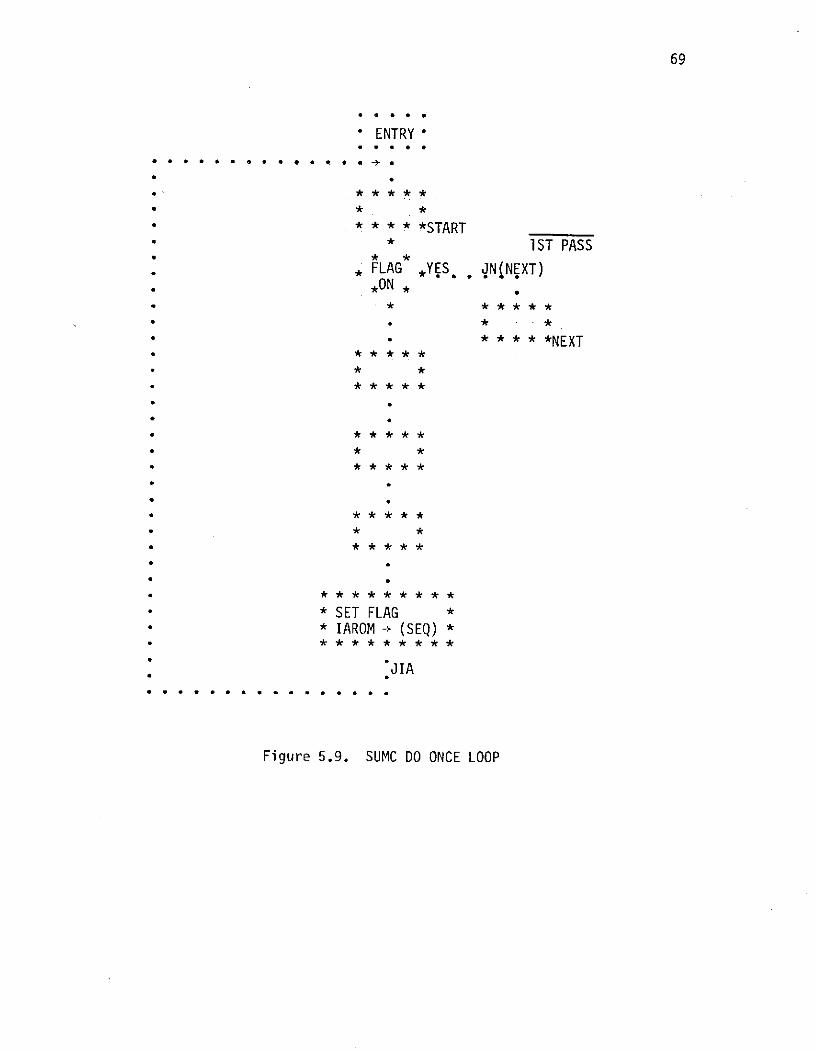
A third type of iterative loop is used in the implementation of the
SI format instructions [6]. Formats are discussed in Section 6.2. This
technique uses a JIA microorder in conjunction with a flag (refer to
Fig. 5.9). During fetch, the flag is set to zero. Some time later in
fetch, the sequencer addresses the microprogram starting location as a
result of JIA microorder. Thus microprogram control is transferred to
this location. The first step of the microprogram checks the flag.
Since it is zero, the sequencer is advanced. Subsequent microinstructions
in the microprogram perform the desired process, f. Then, the flag is

66
changed to a one. To form the loop, a JIA microorder is called.
Since the IAROM is still pointing to the microprogram starting location,
control is once again transferred to this location. Since the tag
is set to a one, the sequencer is loaded with the MROM transfer address.
Thus, control is transferred to some other microprogram. This tech-
nique implements a "one pass" iterative loop.
5.4 Subroutines
The SUMC computer does not have a hardware CALL. However it is
still possible to handle subroutines (and thus implement the CALL) by
using one of the scratchpad temporary registers to store the return
address.
In practice, the process is as follows: at some time during the
microprogram (at a cost of one microinstruction) the desired return
address is stored in a temporary register (usually T5), then at some
subsequent microinstruction the subroutine is entered through an
unconditional jump. The desired subroutine is executed. The last step
of the subroutine consists of gating the temporary register contents to
the sequencer, thus transferring to the previously selected micro-
instruction (return address). This technique, however, does not allow
for subroutine nesting. The SS format flowcharts in Chapter VI illus-
trate the technique.

67
* ENTRY *
* N (T) ** * * * * * * * * F1
*********
* f * 0
S********F1
* (T)-l - (T) ** (PRR) ** * * * * * * * *F
* 2
* * NO JNZ(F 1)* PRR=O * * * * * * * * * * * *
* *
*F3
*YES
* ** * * * * * * * *F
* NEXT *
Figure 5.7. SUMC N-Iterative Loop

68
* ENTRY •
*F
* f *
* (T)+1 + (T) *
* * * * * * * * * F2
* * YES JN(F 1PRM ..NEG,
* NO
* *
* * * * * * * * * F3
.3
* NEXT *
Figure 5.8. SUMC N+1-Iterative LOOP
69
* ENTRY •
*****
**
* * * * *START* 1ST PASS
FLAG YES* J N(NEXT)*ON .
* *****
* *
S* * * * *NEXT*****
* **
*****
*****
****
*********
* SET FLAG ** IAROM (SEQ) **********
JIA
Figure 5.9. SUMC DO ONCE LOOP

70
CHAPTER VI
SUMC BB MICROCODE IMPLEMENTATION
6.1 Emulation
One of the main advantages of a microprogrammable computer is its
emulation ability. Emulation is defined as the imitation of one
system by another such that the imitating system accepts the same data
and programs and achieves the same result as the initial system. There
may be a difference in execution time to achieve the same results.
6.2 IBM System/360 Instruction Formats
The length of an instruction format can be one, two, or three
halfwords. An instruction consisting of only one halfword causes no
reference to main storage. A two-halfword instruction provides one
storage-address specification; a three-halfword instruction provides
two storage-address specifications.
The five basic instruction formats [6] are denoted by the format
codes RR, RX, RS, SI, and SS. These codes express the operation to be
performed. RR denotes a register-to-register operation; RX, a register-
and-indexed-storage operation; RS, a register-and-storage operation; and
SS, a storage-to-storage operation.
6.3 Structured Microprograms
This section contains a subset of SUMC structured microprograms
in flowchart form which emulate the IBM System/360 instruction set [6].

71
Decimal and floating point instructions are not implemented. The
author had intended to code the microprograms represented by the flow-
charts, and run diagnostics on them. However, since the available
hardware is undergoing expansion modifications it was not wise to do so.
A corresponding nonstructured microprogram set (contain floating point
instructions), previously written by the author [21] has been thoroughly
verified by the use of diagnostics. The author exercised great care
not to alter the emulating process; thus, the implemented structured
microprograms should be valid or sufficiently close to valid to allow
realistic conclusions.
The structured microprogram flowcharts shown in Figs. 6.1 through
6.68 are divided into the following groups: RR format, RX format, RS
format, SI format, SS format, and housekeeping. Housekeeping micro-
programs fetch instructions and operands to be executed, and store
program status information.
In the following flowcharts, instruction mnemonics correspond to
those used for IBM System/360 instructions. A microprogram name which
is formed by adding one or more letters to an instruction mnemonic
refers to a continuation microprogram. A continuation microprogram,
unless listed separately in the List of Figures, appears in the same
figure as the instruction mnemonic, the microprogram is listed in the
List of Figures. For example, SIF1 is listed as Fig. 6.27. Instruction
opcodes are shown in hexadecimal form in the upper right hand corner of
the instruction entry block.

72
1A
* AR *
* * ** * ***** ** *
* (AR)+(PRR) + (AR) ** (PRR) ** 0 (MAR) ** -1 + (ER) *
*
YES * * NO * ** . O ALU , .* FTCH
• OF.
* *1 JNOF(FTCH)
* (CCR) - (CC) *
2S J(OF)
* OF *
Figure 6.1. Add Register (AR) Microprogram

73
1E*ALR
* (AR)+(PRR) (AR) ** (PRR) ** O 0 (MAR) *
* J(ALRC)
* ALRC *
*R
* ALRC *
* Kg (ER) ** -1+CL - PRM *
*
NO * * YES * * *.... .. * PRM =1 * ........ ALRD *
+* J(ALRD) ~ . .
* (ER) - (ER) * 1* (ER) RS4 (MQR)* *-1 PRR** + (CC) * *-1 +ER *S******* * ** **
* JNZ(FTCH) * * YESYES * * NO JNZD(FTCH) . . . . . * PRR=O * . . . . .
.... * DEX3 * .... NO * ** * * * * *1 ******
S* * * *** * 2 ..... * O- PRR ** (MQR) Ll1 (CC)* . FTCH * * *(ER) + (ER)*
*** * ** * ** J(FTCH)3
* FTCH * * FTCH * FTCH .
Figure 6.2. Add Logical Register (ALR) Microprogram

74
14
* NR *
* *** * * * **** *
*(AR)A(PRR) - (AR) ** (PRR) ** 0 + (MAR) *
* 1
* J(ALRD)
* ALRD
Figure 6.3. And Register (NR) Microprogram
19
* CR
* ARS V (PRR) PRM ** (MAR) *
*
NO * * YES. . . . . * PRM =1 * a * * ** * * JN(CR+2) ** *1 *
* ** * *** * * * ** * * ** * * * * * * * * *
(AR) - (PRR) + (PRR)* * ARS (PRR) ** 0 (MAR) * * *
2 3
*J(FTCH) J(FTCH) *
* FTCH *
Figure 6.4. Compare Register (CR) Microprogram

75
* BALR
*[(IR) A (KD)]+1PRM** 8-15 *
R2 FIELD = 0 * R2 FIELD 0NO BRANCH NO * * YES BRANCH
* *PRM =1 * * * * * *S* * JN(BALR+2)
* (PC)+2 - (MAR)* * (PRR) + (MAR)*
2 3
* J(BAL) J(BAL) *
* BAL *
Figure 6.5. Branch and Link Register (BALR) Microprogram

76
07
*R
*[(IR)8-15A K6]-1 + PRM* K6 = FFOFFFFF1
* * YES R2 FIELD = 0 . . .*PRM =1 * * * * * * * * * * * * * FTCH
* S * JN(FTCH) * * * ** NO BRANCH* NO
S(IR)-15 A (CC) -1PRM*
2
* * YES RESULT = 0*PRMS=1 * . . . . - FTCH
* * JN(FTCH) * ** NO BRANCH* NO
* (PRR)-2 - (PC) *
3J(FTCH)
* FTCH * BRANCH
Figure 6.6. Branch on Condition Register (BCR) Microprogram

77
06
* BCTR
* * ** *** * * **
* (AR)-1 + (AR) *
* * ** ** ** ** *
*[(IR) IAK6]-+PRM*S** -5*****2
S R2 FIELD = 0* * 2 o *
* PRM=1 * * * * * FTCH* S * J(FTCH) .....
*NO NO BRANCH
* * ** ** ** ** *
* (AR) + PRM ** ** * ** * * * * *
3
YES * ** * * * * * * * * PRM=1 ** * S *
*
NO* ** ** * ** * ** *
* * (AR)-1 PRM ** * *** ** * * * * *
4
* * NO BRANCH* * * YES (AR)=O .
* * PRM=1 * * * * FTCH* * S * J(FTCH) *.. *
NO
* * ** ** * * * * *
* (PRR)-2 - (PC) ** * * * **** ** *
5
J(FTCH) * BRANCH
* FTCH *
Figure 6°7° Branch on Count Register (BCTR) Microprogram

78
5A
* A
*********
*(AR)+(MR) (AR) ** (PRR)** 0 (MAR) ** -1 -+ (ER) **********
YES * * NO * * ** * * * * * * ALU * * * * * * * FTCH ** * OF* JNOF(FTCH) * * * *
1
* (CCR) + (CC) **********
2
*J(OF)
* OF *
Figure 6.8. Add (A) Microprogram

79
4A* AH ** A
*(AR)+(MR) + (AR) ** SHW (PRR) ** -1 ER *
YES * * NO* * * * * * * ALU * * * * * * * FTCH
* OF* JNOF(FTCH)
* (CCR) - (CC) *
2O J(OF)
* OF *
Figure 6.9. Add Halfword (AH) Microprograms
5E
* AL *
* (AR)+(MR) (AR) ** (PRR) ** 0 - (MAR) *
. :JI(ALRC)F ALRC (
Figure 6.10. Add Logical (AL) Microprogram

80
54
* N *
* ** *** **** *
* (AR) (PRR) + (AR) ** (PRR)** 0 + (MAR) ** * * * * ** *** *
* 1:J(ALRD)
* ALRD
Figure 6.11. And (N) Microprogram
59
* C
S* ** ** ** * **
* ARS (MR) PRM ** (MAR) ** ** * * ** * * **
* * YES..... . *PRM =1 * . . .
* * * JN(C+2)
* ** **** ** * ** * * *** * * * *
(AR)-(MR) - (PRR) * * *
0 - (MAR) * * ARS (PRR)* * * * * * * * * * * * * * * * * * * * *
2 3
J(FTCH) ....... (TCH
* FTCH *
Figure 6.12. Compare (C) Microprogram

81
49
* CH
* ** * * * * *
* ARS(MR) + PRM ** SHW (MAR) ** ** * * * * * ** *
* * YES. . . . . *PRMS=1 * . * * * ** * *JN(CH+2)
* ***** ** * * * ** ** * **** * *
(AR)-(MR) + (PRR) * * AR+ (PRR)0 ->(MAR) * * S
* * **** *** ** ** ** **** **
2 3
* J(FTCH) J(FTCH)-
* FTCH
Figure 6.13. Compare Halfword (CH) Microprogram
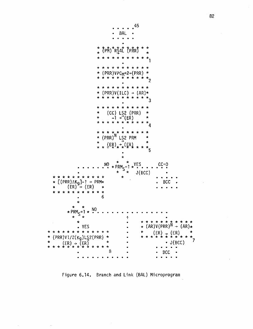
82
45
* BAL
*(PM) R4Lt PRR*** ** ******
1
* (PRR)VPC+2(PRR) *
2* * * * * ** * * **
* (PRR)V(ILC) - (AR)*
3* ** * * ** * * * *
* (CC) LS2 (PRR) ** -1 -+(ER) *
4* * * * * * * * * *
* (PRR)N LS2 PRM *
5
* *
* *NO YES CC=O
* * PRMS =1 * * * * *
* * * J(BCC) ** * * * ** ** ** *
* [(PRR)AKg]-1 + PRM* * BCC(ER) - (ER) * . . .
. 6
NO*PRM=1 * . . . . . * *
* * +* * * * ** ** ** **
. YES * (AR)V(PRR)N + (AR)** * * * ** * * * * * * * * (ER) - (ER) *(PRR)V1/2(Kg)L 2(PRR) * * * * * * * * * * * *
(ER) (ER) * * * J(BCC)* * * * * * * * * * * * * * * * * *
. 8 * * BCC
Figure 6.14. Branch and Link (BAL) Microprogram

83
47
* BC *
*[(IR)8_i5A(CC)]-1PRM** **-1*
*
NO * * YES .....* BCC . ...... *PRIS=1 * ...... FTCH *
.. . * S* J(FTCH) . . .
(MAR)-2 - PC *
. 2
* J(FTCH)
FTCH
Figure 6.15. Branch on Condition (BC) Microprogram
46
* CTo
* (AR)-1 - (AR) ** (PRR) *
S. . . YES * *
* BCC *. o . . . *PRMs=1 ** * . * * J(BCC) * *
*NO
* * * * * NO * * YES* BCC * * * * * * PRR=O * ......* * .* * J(BCC) * *
2 ,
3* J(FTCH)
* FTCH
Figure 6.16. Branch on Count (BCT) Microprogram

84
86
* BXH
* (R3) - (PRR) ** 0 - (ER) *
J(RXIHC) *
* BXHC *
* BXHC
*(PRR)+(RI ) - (PRR) ** (ER) (ER) *
NO * * YES* **.................. * FRS *.......•
• ********** *1 ***********
,,,)-(PPR) DP' * *(R-41)-(PRR) - PRM ** * **** * * * * * * * * * * * * *
* 2 * 4
NO * * YES NO * * YES. *PRM i1 * *PRMS * . * .* * * JN(BXHC46) * * * JN(BXHC+5)*
* ***** * *** *** * * ***** * * *****
*(PRR)R+ ()* *(PRR) (R )* *(PRR)~ (R1)* *(PRR)~(R1)** * * 3 * * * 7 * ** * * * * * 63 7 5 6
.(CTCH) :JBC) .. .J(FTCH) * :J(BCC)* FTCH * * BCC * * FTCH * BCC
Figure 6.17. Branch on Index High (BXH) Microprogram

85
87
* BXLE
* (R3) (PRR) *•* -1 (ER) *
J(BXHC)
* BXHC *
Figure 6.18. Branch on Index Low or Equal (BXLE) Microprogram

86
91
* TM *
S** . .* .
*(ER) - (ER)** ****** *
* *YES ** * ** ERS=1 * . . . * SIF * *
* * JN(SIF) * * * ** JIA
NO
* (To)A(MR) RSJL (PRR) ** O0 (MAR) ** (ER) - (ER) *
3
* (PRR) - 1 - PRM ** (ER) - (ER) *
4
*1/2(To)V(PRR) L.SIA (PRR) ** . (ER) (ER) *
5
* K9 RS4L (PRR) ** (ER) - (ER) *
6
* *
YES * * NO JNZD(TM+7).* * . *(PRR, MAR) * * *
* * ZERO *
* *
* * ** * * * *** ****
* -0 (PRR) * *-I - (PRR) **-1 - ER * *-1 + ER *
7 8
* J(FTCH)
* FTCH
Figure 6.19. Test Under Mark (TM) Microprogram

87
92
* MVI *
* ****** * **
* (ER) + (ER) *
** *****
* * YES * * * * ** ERS=1 * * * * * * * * SIF * * *
* * JN(SIF) * * ** JIA
* NO
* (PRR)V(To) - (PRR ) ** MEM WRITE ** 0 - (ER) *
2
* DELAY **(ER) + (ER) *
3. :J(FTCH)FTCHJ(FTCH)
Figure 6.20. Move Immediate (MVI) Microprogram

88
93
* TS *
* [(MAR)AKo]-1 - PRM** * ** * * ** * **
1
JN(TS+3) YES * * NO.* * * * * *. * PRM=l * .* * * . * ** S **
* * ** ** * ** * * * * * ** ****** *
* (MR) RS4A (MQR) * * (MR) LS4A (MQR) ** - (T2) * * . (T2) ** * ** * * ** ** * ** ** ** * * ** *
4 2
S* * * * * * * * * * * * * * * * * * * * *
*(MR)V(Ki) + PRR * * (MR)V(K2) - (PRR) **MEM WRITE * * MEM WRITE ** ********** ***********
5 3
* * * * * * * .* * * * . * * * * * * *
* (T2) L14 (T2) ** * * * ** * * * *
6
* (T2 )s (PRR) ** *
*0 (MAR) ** -1 + (ER) *
* J(FTCH) 7
* FTCH *
Figure 6.21. Test and Set (TS) Microprogram

89
94
* NI *
* ******** *
* (ER) + (ER) *
********
* * YES * * * * ** ERS=1 * * * * * * * SIF * *
* * JN(SIF) * * * * * JIA*
* NO
* * * * *** * * *** *
* (PRR)V(To)A(MR) -+ (PRR)** MEM WRITE ** (ER) - (ER) ** *** * * ** * ** **
2
*(To)A(PRR) R IL (PRR) ** 0 -+ (MA) ** (ER) (ER) ** * * * * * * * * * * * *
* J(SIF2) 3
* SIF2
Figure 6.22. And Immediate (NI) Microprogram

90
95
* CLI
* * * -* * * * C
*(ER) + (ER)*
* * YES
*ER=1 * * * * * * * SIF * * * * *S* JN(SIF) * * * * * JIA
*
* NO
* * * * * * * * * ** * * * * * *
* (MR) - [(PRR)V(To)] (PRR) ** (ER) - (ER) ** * * * * * * * * * * * * * * * *
.J(FTCH)
* FTCH
Figure 6.23. Compare Logical Immediate (CLI) Microprogram

91
96
* 01 *
***** * * *
* (ER) - (ER) ** ******** *
* 1 * * YES * * * * *
* ER =1 * * * * * * SIF * * * *S * ** * * JIA
* NO
* (MR)V(To) - (PRR) ** MEM WRITE ** (ER) + (ER) ** * * * * * * * * * * ***
2
*J(SIF1)
* SIFI *
Figure 6.24. Or Immediate (OI) Microprogram

92
97
* XI
****** *
*(ER) -+(ER)** ******
1* *
* * YES
* ER5 * * * * * * SIF * * ** * JN(SIF) * * * * * JIA
* NO
*(To)*(MR) (PRR) ** MEM WRITE ** (ER) )(ER) ** * * * * * * ** * * * *
-J(SIF1) 2
* SIF1 *
Figure 6.25. Exclusive Or Immediate (XI) Microprogram

93
* SIF *
*(PRR) L14 (To) ** * * ***** *
1
* [(MAR)AKO]-1 - PRM *
.2
EVEN BYTE ADRESS YES * * NO ODD BYTTE ADDRESS/... . . * * * PRM =1* * * *
JN(SIF+4) * * *S* *
*KIA(MR ) (PRR)* *K2A(MR) - (PRR)** * * * * * * * * * * * * * *
5 3
*(To) LS4A (To) * *(To) RS4L (To) ** * * * ** * * ***
6 4
* J(SIF+6)
* (PRR) (T3) *7
* IAROM - (SEQ) ** -1 (ER) *
8
Figure 6.26. SI Format (SIR) Microprogram

95PRECEDING PAGE BLANK NOT FX"LMF9
D2 D1 D3
* MVC . * MVN * MVZ
**** **** **** **** *********
SK-(MAR) * * K4 (MAR) * * K (MAR) *
* 1 (R) * * 1 -(ER) * * (ER)*** *** ******* * *********
: J(MVCD) : J(MVCD) : J(MVCD)
*MVCD * * MVCD . * MVCD
* MVCD . * MVCX *. . . . .
S******* * *********
* MVCX (Tv) * * MVCY -+ (T5 ) ** ER-~ (ER) * * * * * * * * *
SJ(VCW) * * * * * * *
, J(MVCW) o
*(PRR)V(T 3 ) - (PRR) *
* MVCW • * MEM WRITE *
J(SJb)
* .0 (T .. . . . MVCy MVCX + 2
...... SSFB
* MVC( W * "R ..
*********
* T) * * (T5 )-2 (T5 ) ** 0 (T) * *** * *
* (ER) E R) *•********* J(TRTB) * * * * * * * * * *
J(TRTB).* (T2) (MAR) *
* TRTB * * MEM READ *. . . . *********
J(SSFA)
* SSFA *
Figure 6.28. Move Microprograms (MVC, MVN, MVZ)

96
DD
* TRT *S. . . . * TRTB
* ****** *
* -1 + (T) ** 1 - (E * *********** * * * * * (PRR)N R 4L (PRR) *
1 * (ER)+1 - (ER) *J(TRTA) ** . . . .
* TRTAS* * * * * * * * * *
* (PRR)N RS4L (To) ** (ER)+1 (ER) *
* TRTA * ***********2.TRA 2
* * * * * * * * * * *
* * * * * * * (MAR) (T7)*K2 + (MAR) * * (P R) **(ER) + (ER)* * -(ER) (ER) *
* * * * * * * * * * * * * * * * *
1 3J(TRTB)
* * * * * * * * * * *
TRTB . *(PRR,MAR)N (PRR) *. .. * (T6) *
* (ER) - (ER) *
4
* (B)+D2 (MAR) *** * ******
5
* 0 (T) ** *** ** ***
6
* J(TRA)
* TRA *
Figure 6.29. Translate and Test (TRT) Microprogram

97
* TRTC
********
*(T 1 ) (MAR) ** (MQR) ** 1 (ER) *
YES * * NO* . . .*............* PRR=O* * . . ..........* * * JNZ(TRTC+2)
* *(PRR) RS4L (PRR) ** * (ER) 1 (ER) *
**********
3
S**********
* (MQR) . (ARI) *S* (PRR)N (P
* * (ER)+1 - (ER) ** **********
4
* **********
* * K7 (MAR) ** * (ER)+1 - (ER) ** ***********
* *********
* *(PRR)N RS4L (PRR)** (ER) ' (ER) ***********
6
**********
* (MAR)A(AR2)-(AR 2)* **********
7
**********
* *(AR 2 )V(PRR)-(AR2 )** * -1 - (ER) *** * * * * * * *
8
* J(TRTC+1)
* -(ER) - (ER) ** TRC - (T5) ** 0 - (MAR) *
2
* J(TRTD)
* TRTD *
Figure 6.30. TRTC Microprogram

98
* TRTD
* (ER) + (ER) **(To)-1 - PRM *
NOT LAST BYTE NO * * YES LAST BYTE. .. ............ * PRM.I=1* . ............
* -* * JN(TRTD+3)•****** * *******
(ER) (ER) * 0 (PRR) **(ER)** E*(ER)+(ER) ** * ** * * ********
* 2 4JNX(SSFB) YES * * NO YES * * NO
S* ER =1 * . * . .. * ER * .....Ss* JN(FTCH) * ** * * ******* * * * *
SSSFB * -1 * (PRR)* *I (PRR) *S*-1 - (ER) * * *-1 * (ER) *
3 5
*J(SSFB) ..............J(FTCH)
SSFB FTCH
Figure 6.31. TRTD Microprogram

99
DC
o TR
******
* 1 + (T9 ) ** 1 (ER) ********
:JITRTA)* TRTA *
* TRA
*[(T9)A(PRR)]-1*PRM ** 1 (ER) *
.... YES * * NO . .
*SSF ** ** .. *PRM =1 * . TRB
*** *JN(SSF) * * .**
* TRB *
*** ** **
*(MAR) (Tv)********
J(TRC)
Figure 6.32. Translate (TRTRC) Microprogram
Figure 6.32. Translate (TR) Microprogram

100
* TRC *
* * e * * . * * * *
* TRD * *(T )+(MAR)** *. * * MEM READ *
* 1 - (ER) ** ****** ********TRC + (T5) ** ****** *
* *******
* *TRD + (T5) ** * * * * * * * * * * *(ER)+1 (ER)**(T3 )V(PRR) - (PRR) * * * * * * * ** MEM WRITE * 2
*J SSFB) *[(MAR)AKo]-1 PRM *SSSFB * * (ER)+1 - (ER) *
YES * * NO* . . * * ... . *PRM =1 * * * * * *
JN(TRC+6) * S ** * * * * * * * * * * * * * * * * * * * * * *
* (MR)AK1 RSAL (PRR)* * (MR)AKp (PRR) ** (ER)+1 (ER) * * (ER - (ER) ** * * * * * * * * * * * * * * * * * * * * *
7 4
* J(TRC+4)
* (PRR)N RS4L (T ) ** (PRR) ** (ER) + (ER) *
5
* (Tv) + (MAR) ** 1 - (ER) *
6
* J(SSF)
* SSF *
Figure 6.33. TRC Microprogram

101
* SSF
* (tAR)+(T2)(MAR) ** (T) *
(ER) (ER ** MEM READ *
* J(SSFA)
* SSFA *
Figure 6.34. SS Format (SSF) Microprogram

102
* SSFA
* * *** * * * * **
*(MAR)AKF+1 PRM ** (ER) - (ER) *
NO * * YESS* * * * * PRMS=1 * * a * a *
* * * JN(SSFA+13)* * * * * * * * * * * * * * * * * * *
* ((MAR)AKO)-1 - PRM * * ** (ER) (ER) * * * * * ** 14
NO * * YES * ABERR ** * * * * * * * *PRM =1 * * * * * * * *
* JN(SSFA+14) * *S* * * * * * * * * * * * * * * * * * * * * *
*(MR)A(T 6 ) - (PRR) * *(MR)A(T 7 )L 4A(PRR) *(E) (ER) * * (ER) (ER)
* * * * * * * * * * * * * * * * * * * * * *
15 3
* JN(SSFA+4)* * * * * * * * ** * *
* *(PRR) L4A (PRR) ** * (ER) - (ER) *
4* *
*********
*(PRR) - (T3 ) ** (ER) - (ER) *
5
* (Tg) - PRM ** (ER) - (ER) *
6
YES * * NO * * * * * *S *PRM =1 * * . SSFA+06
* J(TRTC) * * J(SSFA+O6)* . . . . ** * a * * *
* TRTC *
Figure 6.35. SS Format (SSFA) Microprogram
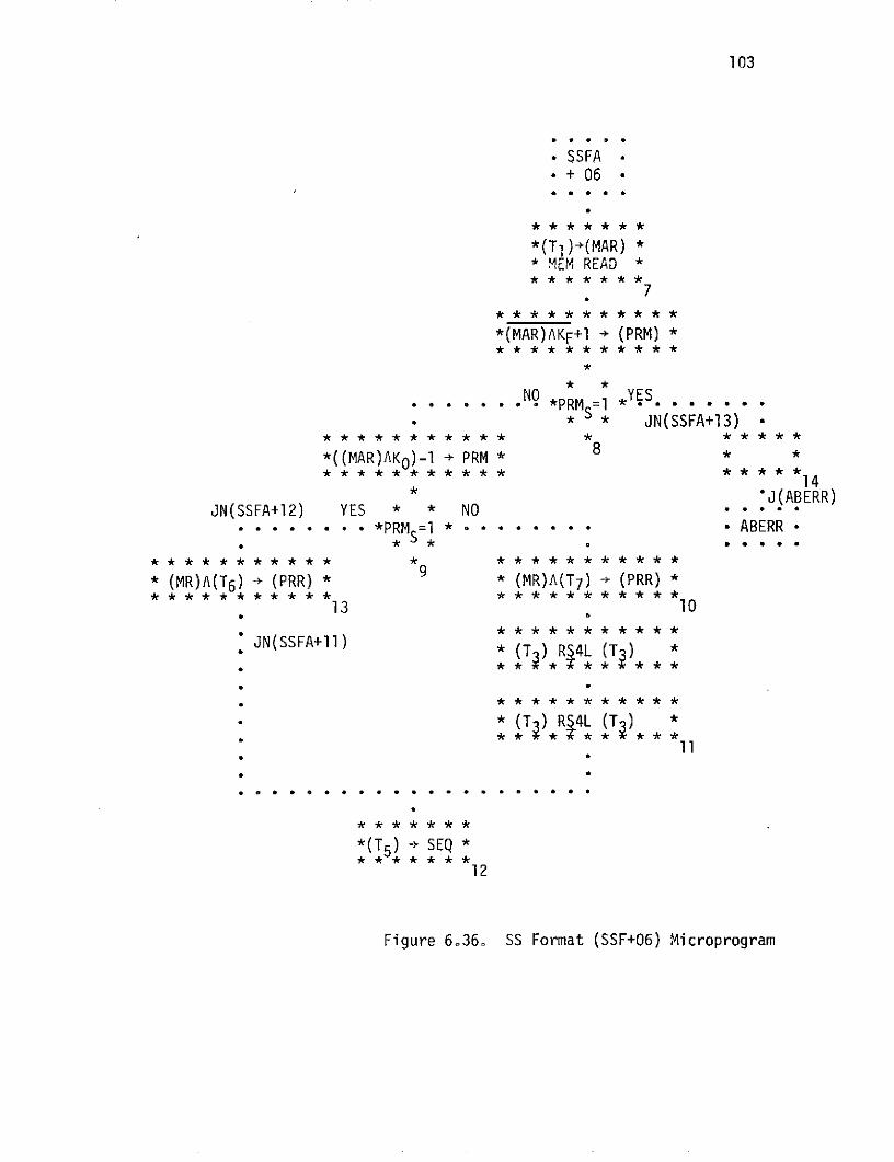
103
* SSFA ** + 06 *
*(TI)*(MAR) ** MEM READ *
7
*(MAR)AKF+1 (PRM) *
* *NO YES. *NO *PRM =1 * * *.
* * S * JN(SSFA+13)• * * * * * * * * * * * * * * * *
8*((MAR)AKO)-1 + PRM * 8 * *S* * * * * * * * * * ** ** *
14• 'J(ABERR)
JN(SSFA+12) YES * * NO ABERR)S .. .. . . *PRMS=1 * .* * * * * * * * ABERR *. * * . * * **
(MR)A(T6 ) - (PRR) * * (MR)A(T7 ) - (PRR) *. * * * * * * * * * * * * * * * * * * * *
13 10* * * * * ** ****
JN(SSFA+11) * (T1) R4L (T3 ) *S* Y * *4L ***
* *
* * * * * * * * * ** *
* * (T3) R.4L (T) *S**** ** *
11
. . . . . . . . . . . . . . . . . . . .
*(T5) SEQ ** * ** * * *
12
Figure 6.36. SS Format (SSF+06) Microprogram

104
* SSFB
* (TO)-1 - (T) *
* 0 + (MAR) *
LAST
NOT LAST NO * * YES *........ **PRM =1 * * *******FTCH ** * 5* J(FTCH) * * *
* F* * * *
SSSFC *
Figure 6.37. SS Format (SSFB) Microprogram

105
SSSFC
S********
*(T2)+I , (T2 ) ** (MAR) ** (ER) - (ER) *
1
* (MAR)AKF+1 PRM ** (ER) - (ER) *
* * YES ADDRESS EXCEPTION*PRMS=1 * * * * * . *
* * JN(SSFC+5) **2 NO
* ******** * *
*(T1)+1 (T) * * * * * *6* (MAR) * 6* (ER) + (ER) * * * JAERR* * * * * * * * * * ABERR
* (MAR)AKF+1 PRM ** (ER) - (ER) *
NO * * YES ADDRESS EXCEPTIONo * * * * * * P =1 * O
* * JN(SSFC+4)• ******** * **********
3
RETURN *(T5 ) - SEQ * 3 * *RETURN *(ER) - (ER) * * *
* * * * * * * * * * * * * * * * * * *
4 5J(ABERR)
* ABERR *
Figure 6.38. SS Format (SSFC) Microprogram

106
* FTCH
* (ER) - (ER) *
NO * * YES JNX(FTCH+3)* * * * * * * * * ER = * * * * * * *
S* ** ** * * * *1 * * ** ** ** *
*(PC)+2 (PC) * *(PC)+2 (PC) ** (MAR) * * (MAR) ** SET FW LATCH * * MEM READ ** * * SET FW LATCH *• ******** *********
2 4
. ******
* (CC) + PSW *S*** ******
5J(FTCH+2.
YES * * NO. * I/0 * . .. . . .
J(IOG) * *. . . . . * 0
SlIOG *
S**** ****
* (PC)-2 + (PC) *
******* *
* FTCH + (T2) ** **** ** *
2SNIO
Figure 6.39* * NIFetch (FTCH) Microprogram
Figure 6.39. Fetch (FTCH) Microprogram
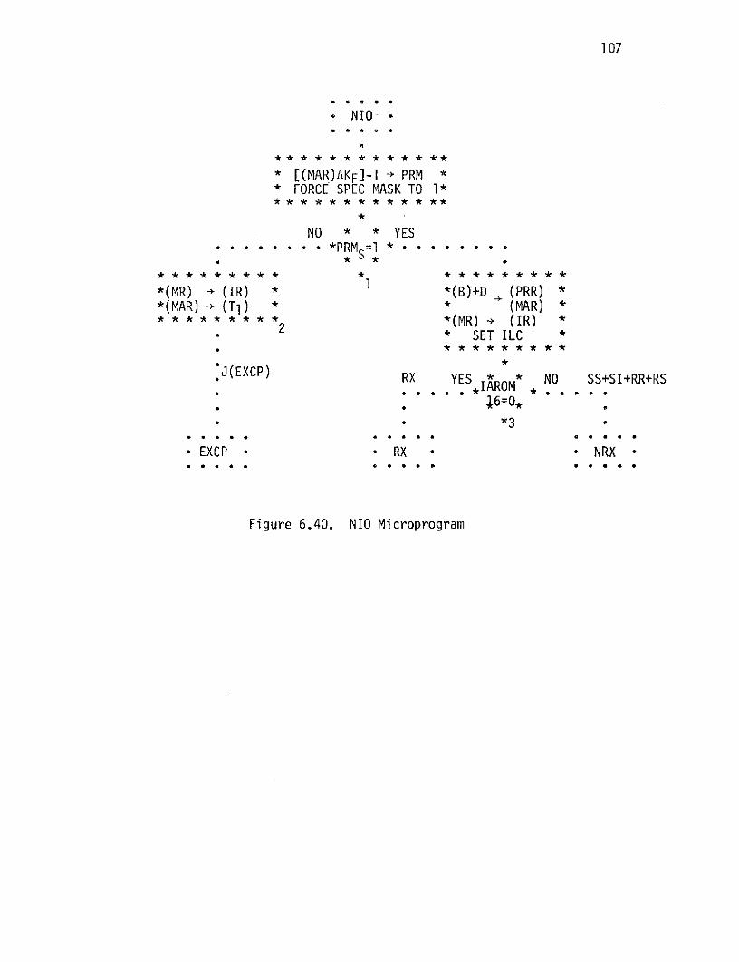
107
SNIO
* * * * * * * * * * * **
* [(MAR)AKF]-1 - PRM ** FORCE SPEC MASK TO 1** * * * * * * * * * * **
NO * * YES* * * . * .* PRM *PM * * * * * . .
*(MR) - (IR) * 1 *(B)+D (PRR) **(MAR) (T1) * * (MAR) *
S2 *(MR) (IR) *2 * SET ILC *
*J(EXCP) RX YES * NO SS+SI+RR+RS.IAROM ......
16=0.S* *3
*EXCP * * RX * NRX
Figure 6.40. NIO Microprogram

108
* EXCP
*(PC)-2 (PC) ** SET ILC **********
1
*********
* 0 + (PRR) ** ILC (MAR) ** -1 ER **********
2
*(PRR,MAR)NR~(PRR) ** (ER) - ER *
3
* (PRR)+(PC) (PC) ************4
*********
*(T1 ) + (MAR) ** * * * * * * * *5
* J(ABERR)
* ABERR *
Figure 6o41. EXCP Microprogram

* RX
*(X)+(PRR) + (MAR) ** OPTIONAL READ ** SET FW' LATCH *
*
YES * * NO.IAROM. ........
* 5=1,0 * . . .. * .*
* ABCHK 1.. *(PC)+2 - (PC) *
. * IAROM SEQ *
*[(MAR)PFFSPAS]-1 PR * * * 4S* * * * * * ' * * * * * * YES * * NO
.. * * * *.. .... * * RSE * * * * ** * • * *
NO * * YES * * * * * * * * * * * * * * **p * PRPMS =1 * ..... *Ko+2 I.1A (PRR)* * EXECUTE
* JN(RX+3) * * * * * * * * * *INSTRUCTION*
2 r
3OFS * FTCH
S J(ABERR) ........
ABERR
Figure 6.42. RX Microprogram

110
SNRX
* (X) -, (PRR) *
1
NO * * YES -.. . .. * *. RSE * . . . . . .
* *
* ******** * * *** ***
*(mR)AK - (PPR)* * EXECUTE ** OPTIONAL READ * * INSTRUCTION ********* *********
* e
YES * * NO * FTCHIARO!M
JIA15(ADCHK)* 5I
AICHK * *(MAR)-.(T 1 )** * ******
* 3
YES * * NO JNRSX(NRX+4)* RSE *...
* k
*. * ** *At A * *
* NO OP * *1K+2 LlA (PRR)**** * * * * * * * * * *
J( ACHK) * J(OFS)
ABCHK * * OFS *
Figure.6.43. NRX Microprogram
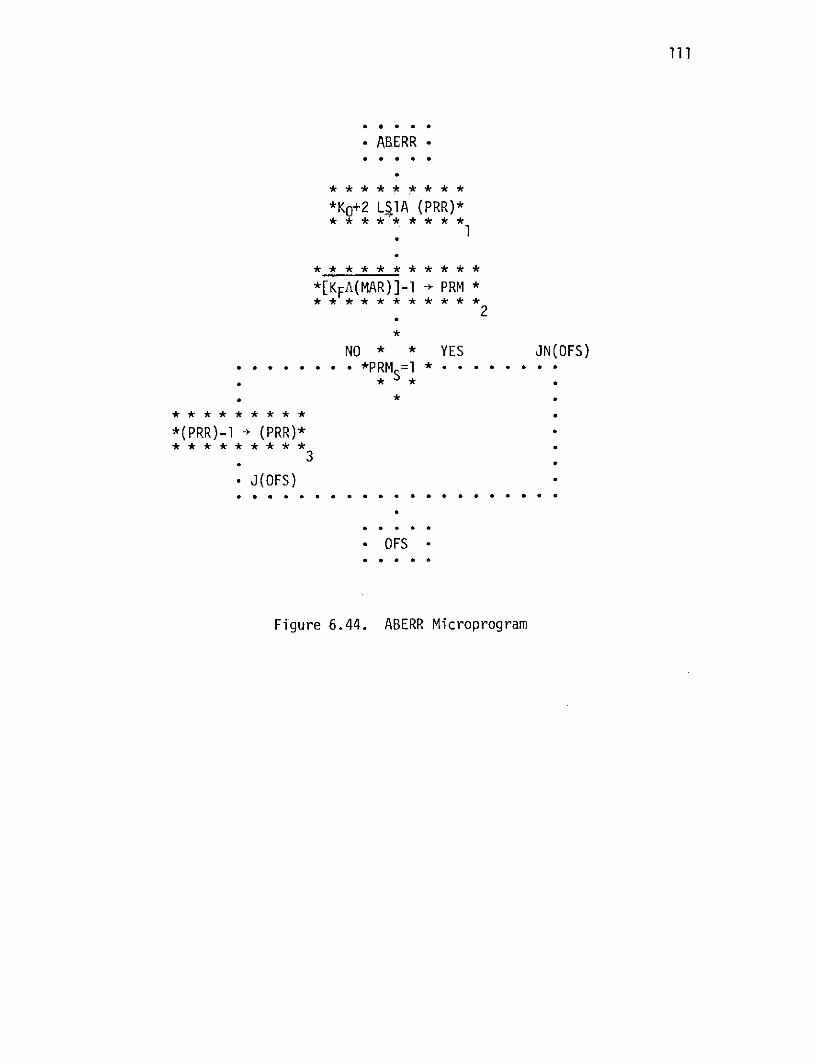
* ABERR *
*** * * ***
*KO+2 L 1A (PRR)*
1
*[KFA(MAR)]-1 PRM *
2
NO * * YES JN(OFS)* * * * * . * . *PRM =1 * * * * * * * *
* ******** *
*(PRR)-1 + (PRR)*
3
* J(OFS)
* OFS *
Figure 6.44. ABERR Microprogram

112
* WAIT
* NO * ******* INT *
1
*YES
* 10 *
Figure 6.45. WAIT Microprogram

113
* * YES ....* INT * .* * * * INT *
* * JINT * * * ** NO
* I/O WORD (MAR) ** MEM READ *
DATA IN NO * * YES DATA OUTS* DOT *.* * * JIDOT(IO+5)
********* * *********
*RESET I/O MUX * 2 * MEMORY READ ** * * * * * * * * * DELAY *
3 *********0 6
********* *
*I/0 WORD (PRR)* * * * * * * *
* MEM WRITE * * (MR) - (PRR) ** SET I/O * * * * * * * * * *
4 ********** (PRR) - I/0 *
7
* * * * * * *
* T2 SEQ *
5
Figure 6.46 10O Microprogram

114
82
* LPSW
*(N) ~1A (PRR) ** -1 (ER) *
.1
*(PRR)N L 4A (PRR) ** (ER) + (ER) *
* 2
PROBLEM STATE YES * * NO SUPERVISOR STATE* * . * . * * * * PRMS=1* * * * * * * *
* * * * * * * * * * * ** * * * * * * * * *
* * * NO OPERATION ** * * * * * * * * * * * * * * * * * * * *
* J(OFS) 4 . 3
S* * * *** * * *
* SUBROUTINE OFS ** * * * * * * * * * *
J(LPS)
* LPS *
Figure 6.47. Load Program Status Word (LPSW) Microprogram

115
* LPS~ •
SUPERVISOR STATENEW SYSTEM MASK
***********
* (MR) (PRR) ** (MQR) ** (SM) *
* (MAR)+4 (MAR) ** MEM READ ** 0 - (SM)M ** -1 + (ER) *
2
* (PRR)N L 4A (MQR) ** (N) ** (ER) + (ER) ** * * * * ******
3S* * * * * **** **
* 0 (N)M ** ( (PRR) NEW KEY AND AWMP
* (MR) (MAR) *
4
* (MR) - (MQR) ** (PC)M * NEW PROGRAM COUNT(PC)M ** (MAR) LJ2L (MAR) ** * * * ** * * *
5
* (MQR) - (PM) ** (ER) + (PRR)+(PRR)*
6***********
* 0 (MQR) ** (PM)M *
7
* (PM) L 4A (PM) *
8
* LPSA *
Figure 6.48. LPS Microprogram
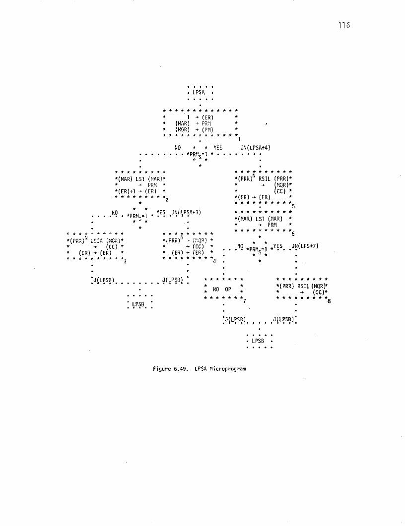
* LPSA *
* 1 - (ER) ** (MAR) - PR:1 ** (MQR) - (PM) ******** ******
NO * * YES JN(LPSA+4)........ *PR, =1 * ..... .
**
********* **********
*(MAR) LSI (MAR)* *(PRR)N RSIL (PRR)** * PRM * * (MQR)**(ER)+1 - (ER) * * (CC) ** * * * * * * * * *(ER) - (ER) *
* *********** * * 5
NO *PRM * ES JN(LPSA+3) * ** * * * * * * **.*PRM=1* *(MAR) LSI (MAR) *
* -* PRM *d*** * ** *********
,(PR")N .SIA (kQR)* *PRR) N ** (CC) * * + (cc) * NO *PR YES JN(LPS+7)
* (ER) - (ER) * * (ER) (ER) * " S .
3 4. *
* * *(PRR) RSIL (MQRYNO OP * (CC)*
LPSB 7 * 8
J'LPSB). ... JJLPSB):
LPSB
Figure 6.49. LPSA Microprogram

117
* LPSB •
* (PC)-2 - (PC) *
* (Z) PRM ** -1 + (ER) *
2
.NO, ,YES JN(LPSB+3)*PRM =1*
* * CHANNEL NOT BUSY *
* * .* **. * *** * *** *****
*(N) LS2 (PRR) * *(K ) (PRR) ** -1 4 (ER) * ** ** ****** *
3
* LPSC * * (PRR) - (I/0) *5
* . * . . J(LPSD)* LPSC •
* ********
*(PRR)N - (PRR) * CHECK PSW* (ER) - (ER) * WAIT BIT
1
* * YES * •*PRMS = * FTCH *
* S * * * 9 * .
JN(FTCH) NO* *
* LPSD
*WAIT+O0 - (T ) ** (SEQ)*
1
Figure 6.50. LPSB, LPSC, LPSD Microprograms

118
* OF
** *******
*(PM) (PRR) **********
* * YES * * *
*PRMS=1 * * * * * * * * * * * FTCH* S* * * * * *
*
*********
* (8) + PRR **********
2
* OFS
NOTE: SUBROUTINE OFS RETURNS TO FTCH
Figure 6.51. Overflow (OF) Microprogram

119
* OFS
***********
* 40 (MAR) ** * * ** * * * * * *
1
* * * * ** * * * * *
* (N) R 4L (MQR) ** * * * * ** * * * *
.2
* (MQR) R4A (SM)***** ** *
3
*(PRR)+(SM) + (PRR) ** MEM WRITE ** 1 + (ER) ************
4
* (MAR)+4 (TO ) ** (ER)+1 - (ER) *
5
* * ** * * * * * * *
*(PM) R.4L (MQR) ** (ER) - (ER) *
6
* (MQR) R4A (MQR) ** (CC) - (MAR) ** (ER) - (ER) *
7
* OFSA *
Figure 6.52. OFS Microprogram

120
* OFSA
* (ER) - (ER) ** (MQR) -, (PM) *
* N PRM *(MAR) MAR *
NO * * YES JN(OFSA+4)..... *PRM =1 * . ........... .
* CC/8 * * CC=8
********* 1 **********(MAR) L1lL PRM * *(PM) L 4L (PRR)* CC=O* (MAR)** * * * *5* (ER) * (ER)** ** * * * * * *
* *J(0FSB)
NO * * YES JN(OFSA+5). *PPRM =1* . . . ...
SCC/4 **S CC=4. .*********** * ***********
*(MAR) LSjL PRM " 2 * 1 (ER) CC=1* (MAR) * *(PM)+(ER) L 4 (PRR)* CC=* (r) (E) ****** *
* * YES JN(OFSA+6)*PRMS=1 *. . . . * . . . . J(OFSB)
*P =I * CC=2 ..* ***********3
* * (ER) + (ER) *CC=1 . NO *(PM)+(ER) Lq4L (PRR)k
* * * * * * * * * * J(OFSB)
* (ER)+1I" (ER) **(ER)+(PM) LS4L (PRR) * *********** ** • .
* * .* J(OFSB)* OFSB *
Figure 6.53. OFSA Microprogram

121
* OFSB *
S*** *** * * ***
* (PRR)+(ILC)+(PC+2) - (PRR)*
*********
* (TO) (MAR) ** MEM WRITE **********
2
*********
* NO OP **********
3
*********
*(MAR)+60(MAR) ** MEM WRITE **********
4
*********
* NO OP **********
5J(LPS)
* LPS *
Figure 6.54. OFSB Microprogram

122
* * * * * * * * * * *
* I/0 (T9) ** * (PRR) ** o0 (MAR) ** MEM READ ** * * * * * * * * * *
1
*15 (PRR) (PRR) ** * * * * * * * * * *
2
* (PRR)-8 (PRM) *
NO * * YES * *. . .. . . *PRM =1 * * * * * * INTL
* * S* *****
*(PRR)-12 + PRM *
INT > 12 NO * * YES 8 < INT. <12* * * * *PRMS=1 * * * * * * * * * *
* * *
* 4 * (PRR)-2 *(PRM) ** * * * * ** * * * * * * ** *
*INTEG12* ** * * * NO * * YES INT-dO
* * * * * *PRMS=1 * * * * * *
* ** * * * * * * * * * * * *
* (PRR)-3 PRM * 5 * * YES* o a********** . PRR * INT8
* 6 ;ERO,
NO YES 7*INT11 * * *PRM =1 * * INT10 * *
* * * * * * * NO
* INT9
Figure 6.55. Interrupt (INT) Microprogram

123
'INTEGj2'
* 3A (PRR) (PRR)** * * * * * * * * * *
* (PRR)-2 - PRM *
* 2
NO * * YES INT < 14* * * * * * * * *PRMS=I * . .* * * *
* * . * * * NO * * YES *..* * * * * * * * * INT13* * * * .... INT12*
*(PRR)-3 + PRM ** * ZER * Q
* 3 4
* * * * * * YES * * * * *
*INT15* * *PRMS=1 * * * * * * INT14 *Figure * * INTEG12 Microprogram * *
Figure 6°56. INTEG12 MicroprOgram

124
. INTL8 .
* (PRR)-4 PRM *
INT > 4 NO * * YES INT <4S- . * PRM =1 * .......
* * * * * * * * * 1 * * YES * * * .
* 3A(PRR)- (PRR)* *PRR=O * . .... INTO********* * * * .o .
2 *S*6 O. < INT <4
* * * *** * * .NO* (PRR)-2 - PRM * * * * * * * * * ** * * * * * * * * (PRR)-2 -f PRM *
INT > 6 * INT < 6 * * * * * * * * *7NO* * YES *
S*PRMS=1 * . " NO * * YES .....* * .. . . *PRM =1 * * * * * *. INTI
** ****** * * * * *
* (PRR)-3 - PRM * 3* * * * * * * * * * (PRR)-3 + PRM *
4 ** ***-**
* * YES*PRM=1 * . ..... INT2
S* * . . . *
NO.NO * * YES. .. *
INT6* * PRMS=1 * . . .INT7 *.. * * INT3
* * * * * * * C * C
* INT5 . * . . *PRR=O * YES INT4.mm . * * * **
*5
Figure 6.57. INTL8 Microprogram

125
* INTO
* (PRR)* I/O *
* (PRR) - I/0 *
* LPS
* INT1
*********
* (PRR) + I/0 *
1
* LPSC(T3)
* INT2 3
* 24- (T3) **********
1
* INT23 *
* INT3 , INT Microprogram
* 56 T3*********
1
* INT23 *
Figure 6.58. INTO, INT1, INT2, INT3 MicrOprOgrams

126
* INT23 *
* . Z ** 0 + PRR *
* RESET I/0 *
2
* I/O + (MAR) ** SET I/0 *
3
*(MARASM)-1 - PRM** 1- ER) *
* 4
CHANNEL ENABLED NO * ** * * * * * *PRM =1 ** * *
* ******** *
*K8 L 1A (PRR) * YES
5 8*
* (T)** ** *INTF*
* (PRR) + I/O * * * * * * * * * **(MAR)AK8 (PRR)* * (PRR) I/0 ** * * * * * * * * * * * * * * * * *
6 9
* (T,3) MAR * * INTF *
7
* OFS *
Figure 6.59. INT23 Microprogram

127
* INT4 * 0* INT5 *
* * ****** * **
* (PRR) - I/O ** (PRR) - I/0 *0 (Z)
* *********
* INTF *I/0 WORD 2+(CC)** SET I/O ** **** *****
* FTCH *
* INTF* * INT6 * * INT7 *
** *** * ********* ** ******
* WAIT SEQ * * (PRR) I/O * PRR I/O ** (T2 ) * * * * ****** * 0 + (Z)
* * * * * * * * * *
* I/O WORD2 (z)* .* SET I/O * * INTF *
2
* (T2 ) + SEQ *
3
Figure 6.60. INT4, INT5, INT6, INT7, INTF Microprograms
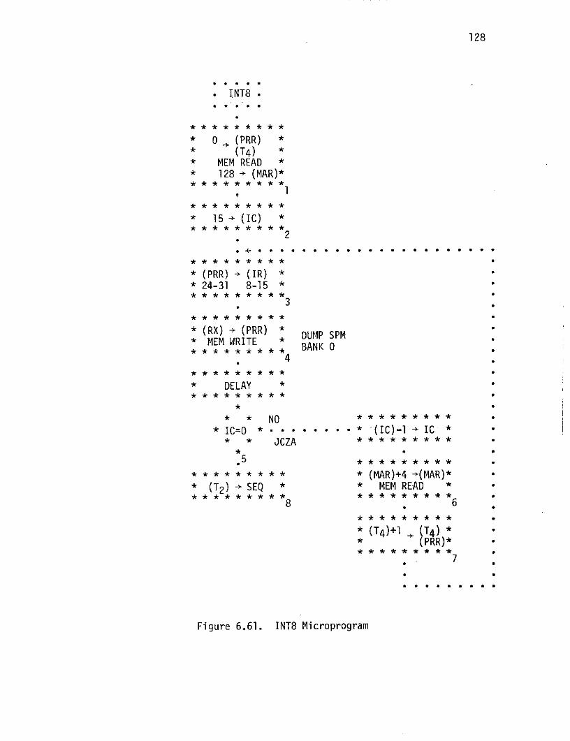
128
. INT8 .
******* *
* 0 (PRR) ** (T4) ** MEM READ *• 128 - (MAR)*
1
* 15 - (IC) *
2
* ********
• (PRR) + (IR) ** 24-31 8-15 *
******** *3
* ******** *
* (RX) (PRR) ** MEM WRITE * DUMPSPM.0 .. .BANK 0
4
******** *
* DELAY *********
* * NO ********* °
* IC=O * * * * * * * * * (IC)-1 IC ** *********CZA
*5* * * * * * * * * (MAR)+4 *(MAR)*
* (T2) - SEQ * * MEM READ ** * * * * * * * * * * * * * * * *
8 6
* (T4 )+1 (T4 ) ** (PRR)*
7
Figure 6.61. INT8 Microprogram
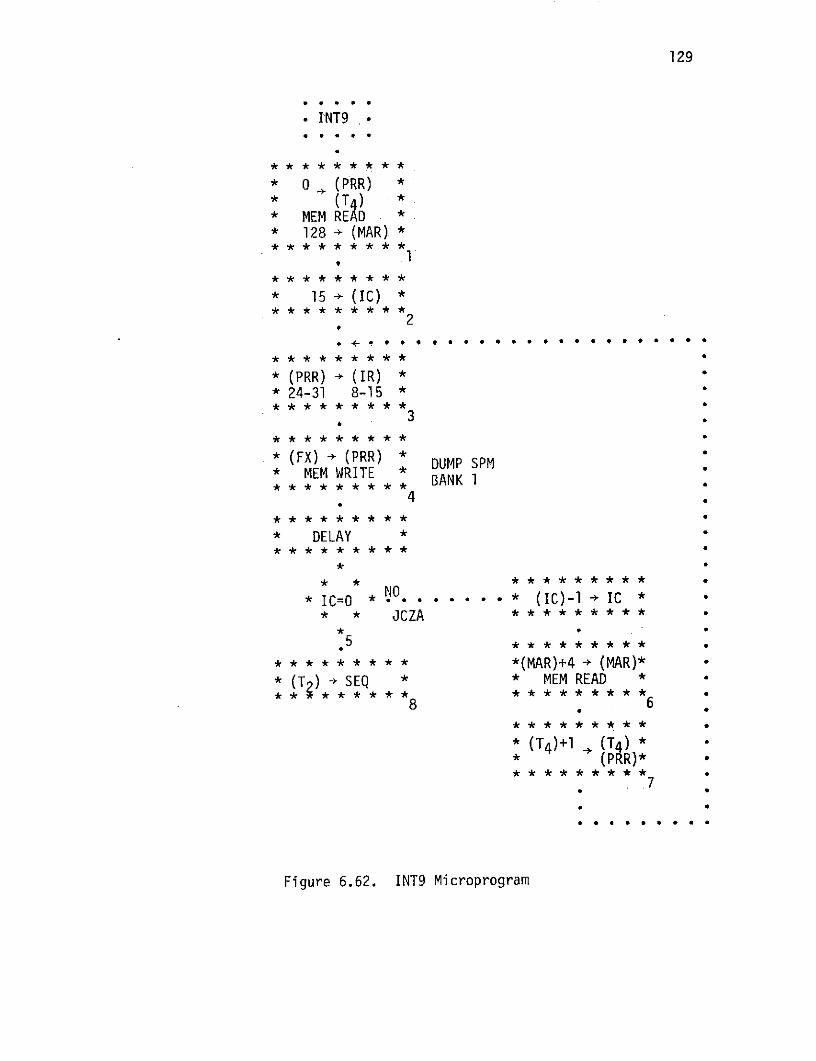
129
* INT9 **INT9
*********
* 0 (PRR) ** (T4) ** MEM READ *• 128 + (MAR) *
* 15 + (IC) *
2+ 9 9 * * * 9 9 9 9 9 * * 0 9 * * * * * *
• ******** *
(PRR) - (IR) ** 24-31 8-15 *• **** * ** *
3S** ******
* (FX) + (PRR) ** MEM WRITE * DUMP SPM
* * * * * BANK 14
• ******** *
* DELAY *
* * *********
* IC=O .NO* * * * * * (IC)-1 IC *
* * JCZA * * * * * * *
5 ****** ***
S * * * * * *(MAR)+4 - (MAR)*S(T2) SEQ * * MEM READ *
* * * * * * * ** * ** ** * *
******** 6
* (T4)+1 (T4) ** (PRR)********* *
7
Figure 6.62. INT9 Microprogram

130
* INT10 *
* 0 (PRR) ** (T) *
* MEM READ ** 128 + (MAR) *
* 15 - (IC) **********
2
* **** *- * *
* (PRR) + (IR) ** 24-31 8-15 *• ******** *
. 3
* ******** *
* (T) - (PRR) * DUMP SPM* MEM WRITE ** * * * * * * * BANK 2
4* * *** * *
* DELAY ** ******** *
* * NO ********** IC=O * * * * * . * * * (IC)-1 +IC *
* * JCZA * * * * * * * *
*5 ** *********
* * * * * * * * * *(MAR)+4-+ (MAR)** (T ) SEQ * * MEM READ ** * 5 * * * * * * * * * * * * * *
8 6* ******** *
* (T4 )+l (T *•* (PRR)********* *
7
Figure 6.63. INTO10 Microprogram

131
* INT11 l
* 0 (PRR) ** (T4) ** MEM READ ** 128 (MAR) **********
* 15 (IC) *
2
******* * * *
* (PRR) (IR) ** 24-31 8-15 ** ******** *
3* ******** *
* (YX) - (PRR) * DUMP SPM* MEM WRITE * BANK 3* ******** *
4* ******** *
* DELAY *********
* * NO * * * * * * * * *
* IC=O * * * * * * * * * (IC)-I IC ** * JCZA * * * * * * * * *
5 *
* * * * * * * * * *(MAR)+4 (MAR)** (T2 ) SEQ * * MEM READ ** * * * * * * * * * * * * * * * *
8 6S********
* (T4 )+1 (T4) * .* (PRR)*
7
Figure 6.64. INT1I Microprogram

132
* INT12 *
*********
* 0 (PRR) *(T
* MEM REA ** 128 - (MAR)*
1
* 15 + (IC) *
2
* ******** *
* (PRR) (IR) ** 24-31 8-15 ** ******** *
3S******* **
* (MR) (RX) *LOAD SPM* * * * * BANK 0
* ********
* DELAY ** ******** *
* * NO * * * * * * * * *
* IC=O * * * * * * * * * (IC)-1 - IC ** * JCZA * * * * * * ***
5 *********
*5* * * * * * * * * *(MAR)+4 + (MAR)** (T2) SEQ * * MEM READ ** * * * * * * * * * * * * * * *
8 6S******** *
* (T4 )+1 (T )** (PRR)** ******** *
7
Figure 6.65. INT12 Microprogram

133
* INT13
0 (PRR) ** (T4 ) ** MEM READ *• 128 - (MAR) *
1
* 15 + (IC) *
2
******** *
* (PRR) (IR) ** 24-31 8-15 *
******** *3
*********
(MR) (FX) * LOAD SPMBANK I4
* *** ***
* DELAY *********
* * NO ********** IC=O * * * * * * (IC)-1 IC *
* * JCZA * * * ** * * * **5 . * *
*5* * * * * * * * *(MAR)+4 (MAR)*
* (T2 ) SEQ * * MEM READ *S* * * * * * * * * * * * * * * * *
8 6* ******** *
* (T4)+1 (T4) ** (PRR)** ******** *
7
Figure 6.66. INT13 Microprogram

134
* INT14 *
* (PRR) ** -(T4) ** MEM READ ** 128 + (MAR) *
1
* 15 IC *
2
* ******** *
* (PRR) (IR) ** 24-31 8-15 ********* *
3* ******** *
* (MR) - (T) * LOAD SPM* * * * * * * * * BANK 2
4* * C*******
* DELAY ** ******** *
* * NO ********** IC=O * * * * * * * * (IC)-1 IC *
* * JCZA * * * * * * * * *
.5 *********
* * * * * * * * * *(MAR)+4 + (MAR)** (T2 ) - SEQ * * MEM READ ** * * * * * * * * * * * * * * *
8 6
* ******** *
* (T4 )+l (T4)** (PRR)** ******** *
7
Figure 6.67. INT14 Microprogram

135
* INT15 *
* 0 (PRR) ** (T4) ** MEM READ ** 128 (MAR) *
* 15 - (IC) *
2
S** -*** * *
* (PRR) - (IR) ** 24-31 8-15 ** ******** *
3* * * * * * * * * LOAD SPM
LOAD SPM* (MR) (YX) * BANK 3* ******** *
4S******** *
* DELAY ** ******** *
* * NO ********** IC= * * * * * * . * * * (IC)-1 - IC *
* * JCZA * * * * * * * * **5 ** *********
* * * * * * * * * *(MAR)+4 (MAR)** (T ) + SEQ * * MEM READ *
S* * * * * * * * * * * * * * * *
8 6S******** *
* (T )+l (T) ** (PRR)** ******** *
7
Figure 6.68. INT15 Microprogram

136
CHAPTER VII
COMPARISON
7.1 Conclusions
A comparison of the structured and nonstructured microprograms
used in the emulation of the IBM System/360 by the SUMC BB brought
to light the following conclusions:
1. Structured instruction microprograms were essentially as
efficient as the corresponding nonstructured microprograms. That is,
execution time and microprogram size remained essentially the same.
2. The implementation of structured housekeeping microprograms
(Fetch, Overflow, Interrupt, etc.) was considerably more difficult.
In general, these structured microprograms were slower and occupied
more control memory locations than the nonstructured ones. For instance,
in the Interrupt microprograms the lack of a CASE (COMPUTED GO TO)
statement primitive forces the microprogrammer to use 15 decision
blocks rather than one to decide which interrupt to process. This
represents up to a 30 percent reduction in speed (execution speed varies
with each interrupt processed), and a 16 percent increase in the size
of the microcode memory portion which handles interrupts. Furthermore,
note that INT8, INT9, INT10O, INT11, INT12, INT13, INT14, and INT15 are
identical except for Step 4. These microprograms could be combined by

137
using the forbidden CASE primitive. Because of this restriction, the
size of the structured Interrupt microprogram subset is 200 percent
greater than the size of the nonstructured Interrupt microprogram
subset. There were no significant changes in speed or size for Fetch
and Overflow microprograms. The author feels the housekeeping area is
the crucial one when implementing structured microprograms because real
time response limitations or control memory size restrictions may not
permit the microprogrammer to use structured primitives wholly in
housekeeping microprograms.
3. Structured RR, RX, RS and SI format microprograms were easily
implemented in the SUMC;speed and microcode memory size were not
sacrificed.
4. Structured SS format microprograms remained as fast as the
nonstructured ones. However, it was not possible to share microcode
memory locations, within these microprograms, as easily as it was with
the nonstructured microprograms. Consequently, the microcode memory
size was increased by 15 percent for the structured set.
5. Structured microprograms were better organized and thus should
be more readily and quickly understood by users.
One must not forget that microprogramming is machine dependent.
Thus, these conclusions apply only to the SUMC BB.
7.2 Further Research
The study of the branching architecture required for ease of imple-
mentation of structured microprograms is not complete. The branching
architecture of other microprogrammable machines and of the newly
developed microprocessors should be studied.

138
REFERENCES
1. Dijkstra, E. W., "The Structure of the 'THE' MultiprogrammingSystem", Communications of the ACM, May 1962.
2. Gimenez, C. R., and Williams, C. A., SUMC BB/360 MicroprogrammersReference Manual, Sperry Rand, 1974.
3. Glushkov, V., "Automata Theory and Formal MicroprogramTransformations", Kibernetika, Vol. 1, No. 5, 1965.
4. Glushkov, V., "Automata Theory and Structural Design Problems ofDigital Machines", Kibernetika, Vol. 1, No. 1, 1965.
5. Glushkov, V., "Minimization of Microprograms and AlgorithmSchemes", Kibernetika, Vol. 2, No. 5, 1966.
6. IBM System/360 Principles of Operation, IBM Systems DevelopmentDivision, Publication No. GA22-6821-8, May 1970.
7. Intel 8080 Single Chip Eight Bit Parallel Central Processor Unit,Intel, April 1974.
8. Ito, T., "A Theory of Formal Microprograms", Sigmicro Newsletter,Vol. 4, No. 1, April 1973.
9. Ito, T., "On Proving the Correctness of Programs", Fourth PrincetonConference on Information Sciences and Systems, 1970.
10. Ito, T., "Some Formal Properties of a Class of Program Schemata",IEEE Symposium on Switching and Automata Theory, 1968.
11. Jones, L. H., "The Role of Instruction Sequencing in StructuredMicroprogramming", Sigmicro Newsletter, Vol. 4, No. 3, October 1973.
12. National Semiconductor IMP 8 Programming Manual, National Semi-conductor, December 1973.
13. Navy Electronics Laboratory, "Microprocessor Developments forProject 2175", August 1973.
14. Mills, Harlan, "Mathematical Foundations for StructuredProgramming", IBM Research Report FSC 72-6012, February 1972.
15. G. Noguez, "A Standardized Microprogram Sequencing Control with aPush Down Storage", Fifth Annual Workshop on Microprogramming,University of Illinois, 1972, (Preprints).

139
REFERENCES(Concluded)
16. Reigel, E. W., Faber, U., and Fisher, D. A., "The Interpreter --A Microprogrammable Building.Block System", AFIPS ConferenceProceedings, Vol. 40, SJCC 1972, pp. 705-723.
17. Roberts, J. D., Jr., Ihnat, J., and Smith, W. R., Jr.,"Microprogrammed Control Unit (MCU) Programming ReferenceManual", Sigmicro Newsletter, Vol. 3, No. 3, October 1972.
18. Space Ultrareliable Modular Computer (SUMC), S&E-ASTR-C-005,1972.
19. SUMC Microinstruction Assembler, S&E-ASTR-C-002, Rev. A,October 1972.
20. SUMC 360 Microcode and Microprogram Flowcharts, Sperry Rand,December 1972.
21. SUMC 360 Microcode and Microprogram Flowcharts, Sperry Rand,December 1973.
22. Tenny, Ted, "Structured Programming in Fortran", Datamation,July 1974.
23. Yourdon, E., "A Brief Look at Structured Programming and TOPDOWN Program Design", Modern Data, June 1974.

140
APPENDIX A
NOTATION
Symbol Meaning
=: is loaded into
corresponds to or is related to
corresponds to
A - B mapping of A into B
+ loaded into
* concatenation
<a v b > if p then a; if not p then bp
[b] while p do bp
( ) contents of
V logical OR
V- exclusive OR
A logical AND
logical NOT
logical NOT
< less than
not less than
equal to
not equal to

141
APPENDIX B
FLOWCHART. CONVENTIONS
* Entry or exit point.
* * Microinstruction cycle.
* * Decision block.
lower case letter => a function of process
within a micro-instruction cycleor decision block
upper case letter => MROM location
on lower right handcorner of a micro-instruction cycleor decision block

142
EXAMPLES
Example Explanation
* * * * * Microinstruction cycle
fl * with decision block.F1 refers to MROM location;
F1 fl to some function per-
* *formed during Fl; dl refers
Sdl * to some decision performed
. . during Fl.
.. . . Microprogram begins at
* ENTRY * microinstruction cycle F1is followed by decision
block F2. d2 refers tosome decision performedduring F2 ; if the condition
S f * checked for during F2 is
* * * * * * * true, a No-Operation cycle
F1 F3 is performed prior to
. going to EXIT; if the* condition checked for during
NO * * YES F2 is false; f4 is performed
S. d2 * .... during microinstructionS . . cycle F4 prior to EXIT.
*F2
* *** * *f4* f4 * * *
* F4 F3
* EXIT* • • a a

143
APPENDIX B
FLOWCHART SYMBOLS
( ) Contents of
A Logical "AND" operation
V Logical "OR" operation
Logical "EXCLUSIVE OR" operation
+ Addition
Subtraction
-T One's complement
-( ) Negation (Two's complement)
- Data transfer or flow
N (Used either as a subscript or superscript). Normalized
LS4A Left shift four arithmetic bits
LS2A Left shift two arithmetic bits
LS1A Left shift one arithmetic bits
LS4L Left shift four logical bits
LS2L Left shift two logical bits
LS1L. Left shift one logical bits
RS4A Right shift four arithmetic bits
RS1A Right shift one arithmetic bits
RS4L Right shift four logical bits
RS1L Right shift one logical bits

144
APPENDIX B
FLOWCHART ABBREVIATIONS
AR Accumulator Register
ALU Arithmetic Logic Unit
B Base Register
CC Condition Code
CCR Condition Code Register
D Displacement Field
DEX Derived Exponent
EALU Exponent Arithmetic Logic Unit
ER Exponent Register
IAROM Instruction Address Read-Only-Memory
IC Iteration Counter
IR Instruction Register
K SPM Mask Registers (see Appendix C)
M Program Mask
MAR Memory Address Register
MAM Memory Address Multiplexer
MQR Multiplier/Quotient Register
MR Memory Register
MROM Microcode Read-Only-Memory
N Interrupt Status Register
OF Overflow
PC Program Counter

145
FLOWCHART ABBREVIATIONS(Concluded)
PRM Product Remainder Multiplexer
PRR Product Remainder Register
R Register
ROM Microcode Read-Only-Memory
S System Mask
SPM Scratch Pad Memory
T Temporary Register
X Register

146
APPENDIX B
FLOWCHART SUBSCRIPTS
M Mantissa
N Normalized * Also used as a superscript
OF Overflow
S Sign bit
SHW Sign Extended Halfword
V Used with Temporary register Tv
O-F Hexadecimal 0-15
+1 Register specified by selected IR field +1

147
APPENDIX C
SPM MASK REGISTERS
K0 = 00000001
K1 = OOFFFFFF
K2 = FFOOFFFF
K3 = FOFFFFFF
K4 = FFFOFFFF
K5 = OFFFFFFF
K6 = FFOFFFFF
K7 = FFFFFFOO
K8 = 0000FFFF
K9 = 01000000
KA = OOFF0000
KB = F000000
Kc = OOFO0000
KD = 000FFFFF
KE = O000F000
KF = OOFF0000

148
APPENDIX D
EXTERNAL INTERRUPTS
Name Function
INTO Power Up
INT1 Release CPU
INT2 External Interrupt
INT3 Channel 1
INT4 System Reset
INT5 Set Condition Code
INT6 Set Channel Busy
INT7 Initial Program Load
INT8 Store SPM Bank 0
INT9 Store SPM Bank 1
INTO1 Store SPM Bank 2
INT11 Store SPM Bank 3
INT12 Load SPM Bank 0
INT13 Load SPM Bank 1
INT14 Load SPM Bank 2
INT15 Load SPM Bank 3