atcamsoftx3000 hardware introduction issue2.1
DESCRIPTION
ATCAMSOFTX3000 Hardware Introduction ISSUE2.1TRANSCRIPT
HUAWEI TECHNOLOGIES CO., LTD.
www.huawei.com
HUAWEI Confidential
Security Level:
MSOFTX3000 Hardware Introduction

HUAWEI TECHNOLOGIES CO., LTD. HUAWEI Confidential Page 2
Objectives
Hardware configuration, types of buses and
their functions
Functions, external interfaces, cable
connection, and DIP setting of boards
Signal flow among boards
Cable configurations
Upon completion of this course, you will
understand:
HUAWEI TECHNOLOGIES CO., LTD. HUAWEI Confidential Page 3
Contents
Chapter 1 Overview
Chapter 2 Overall System
Chapter 3 Boards
Chapter 4 Signal Flow
Chapter 5 Cable Connection

HUAWEI TECHNOLOGIES CO., LTD. HUAWEI Confidential Page 4
Chapter 1 Overview
Section 1 Introduction to the Section 1 Introduction to the
MSOFTX3000MSOFTX3000
Section 2 Hardware Platform
Evolution
Section 3 OSTA2.0 Platform
HUAWEI TECHNOLOGIES CO., LTD. HUAWEI Confidential Page 5
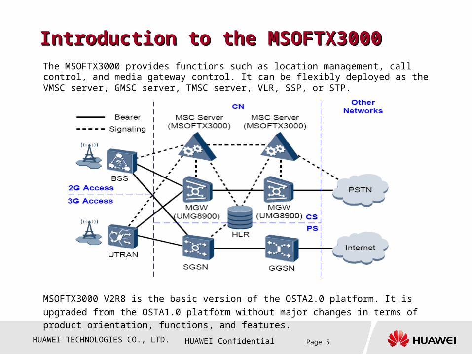
Introduction to the MSOFTX3000Introduction to the MSOFTX3000The MSOFTX3000 provides functions such as location management, call control, and media gateway control. It can be flexibly deployed as the VMSC server, GMSC server, TMSC server, VLR, SSP, or STP.
MSOFTX3000 V2R8 is the basic version of the OSTA2.0 platform. It is upgraded from the OSTA1.0
platform without major changes in terms of product orientation, functions, and features.

HUAWEI TECHNOLOGIES CO., LTD. HUAWEI Confidential Page 6
Chapter 1 Overview
Section 1 Introduction to the Section 1 Introduction to the
MSOFTX3000MSOFTX3000
Section 2 Hardware Platform Section 2 Hardware Platform
EvolutionEvolution
Section 3 OSTA2.0 Platform

HUAWEI TECHNOLOGIES CO., LTD. HUAWEI Confidential Page 7
CPCI Platform Structure
Centralized power supply: The UPWR supplies power for all boards in a subrack.
Dual CPCI (compact pci) buses (that is, resource-sharing buses A and B) with the bandwidth of 2×2Gbps
Ethernet dual-platform and dual-star architecture
Master and slave serial buses
H.110 bus, providing switching capability of 4096 timeslots and 256 Mbps bandwidth

HUAWEI TECHNOLOGIES CO., LTD. HUAWEI Confidential Page 8
Limitations of the CPCI Platform Low scalability
Complex bus types and limited bandwidth:
CPCI bus: 2 x 2 Gbps
H.110 bus: 256 Mbps
Ethernet bus: 24 x 100 Mbps (in spite of expansion) Limitations related to the power supply, structure, and heat dissipation: The maximum power consumption of
a single slot (50 W) constrains the performance improvement of boards. Not hot-swapping sub boards
Low reliability The bus structure has inherited faults and potential single-point failures, for example, centralized power
supply, CPCI bus, and master/slave serial bus The device control flow cannot be separated from the service flow. This may cause security problems.
Non-authentic Open Standard Platform Carrier-specific standard: Expanded with multiple private interfaces based on the original CPCI standard (for
example, Ethernet bus, H.110 bus, back board size, and main/slave serial port bus) No standard open software interface; tight coupling of hardware and software High lifecycle costs
HUAWEI TECHNOLOGIES CO., LTD. HUAWEI Confidential Page 9
ChallengesWith the development of the telecom industry, carriers are increasingly having higher requirements related
to telecom devices, especially in the following aspects:
Simplicity: The platform should be capable of simplifying the design, manufacture, test, and application of
network devices.
Capacity: The platform should provide sufficient bandwidth, call rate, processor loading rate, and operating
efficiency to meet the current and future requirements.
Performance: The platform should be capable of supporting short delay and call setup duration and providing
high service performance and QoS.
Reliability: The reliability of the platform should reach 0.99999.
Serviceability: The platform should be capable of providing simple, strong, and cost-saving OAM&P.
Security: The platform should be capable of protecting key services from being intercepted and against
Hacking.
Time to Market: Time to market for a new product should be shortened. (purchasing boards, subracks,
Middleware, and APIs from other vendors to reduce development workload)
Cost: Lifecycle costs should be reduced. (software and hardware architectures can ease the multiplexing among
different products and reduce development workload)
Regulatory Considerations: The platform should comply with international specification and standards.

HUAWEI TECHNOLOGIES CO., LTD. HUAWEI Confidential Page 10
ATCA Specifications Advanced Telecommunications Compute Architecture (ATCA ) is the largest specification effort in the
history of the PCI Industrial Computer Manufacturers Group (PICMG), with more than 100 companies participating. It includes serials of specifications, for example, PICMG3.0, PICMG3.1, PICMG3.2, PICMG3.3, and PICMG3.4.
Sub-specifications:
3.1: Ethernet and Fiber channel Transport
3.2: Infini Band Transport
3.3 : Star Fabric Transport
3.4 : PCI Express Transport
3.5 : Advanced Fabric Interconnect / Serial Rapid IO
AMC module specification: hot swapping and sub board specification
The ATCA specification is developed based on the CPCI specification. It meets the new requirements of the telecom industry with the following features:
Dual -48 VDC redundancy power
High-speed differential signal connector and high bus bandwidth
Proper board size (8U x 280mm) and slot distance (1.2 inch) for ease of heat dissipation
Hot-swap high-speed subboards
Standard IPMI bus for the management of any parts in the system
Open software and hardware architecture with the CGL operating system
Compliance with the NEBS and ETSU standards
High reliability with the dual-star architecture for service buses
HUAWEI TECHNOLOGIES CO., LTD. HUAWEI Confidential Page 11
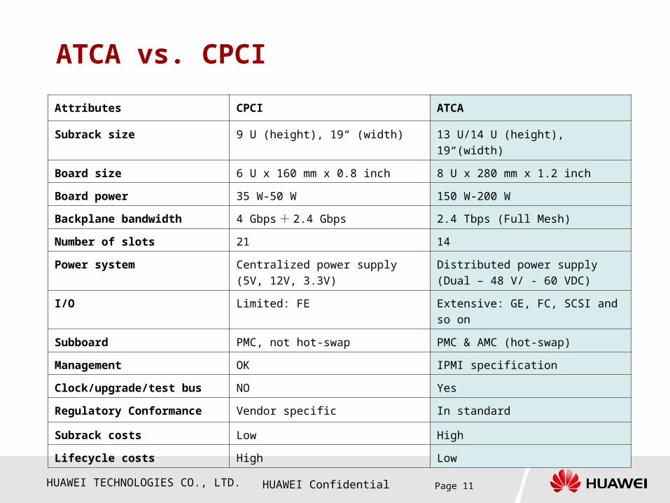
ATCA vs. CPCI
Attributes CPCI ATCA
Subrack size 9 U (height), 19“ (width) 13 U/14 U (height), 19“(width)
Board size 6 U x 160 mm x 0.8 inch 8 U x 280 mm x 1.2 inch
Board power 35 W-50 W 150 W-200 W
Backplane bandwidth 4 Gbps + 2.4 Gbps 2.4 Tbps (Full Mesh)
Number of slots 21 14
Power system Centralized power supply (5V, 12V,
3.3V)
Distributed power supply (Dual – 48
V/ - 60 VDC)
I/O Limited: FE Extensive: GE, FC, SCSI and so on
Subboard PMC, not hot-swap PMC & AMC (hot-swap)
Management OK IPMI specification
Clock/upgrade/test bus NO Yes
Regulatory Conformance Vendor specific In standard
Subrack costs Low High
Lifecycle costs High Low

HUAWEI TECHNOLOGIES CO., LTD. HUAWEI Confidential Page 12
Chapter 1 Overview
Section 1 Introduction to the Section 1 Introduction to the
MSOFTX3000MSOFTX3000
Section 2 Hardware Platform Section 2 Hardware Platform
EvolutionEvolution
Section 3 OSTA2.0 PlatformSection 3 OSTA2.0 Platform
HUAWEI TECHNOLOGIES CO., LTD. HUAWEI Confidential Page 13
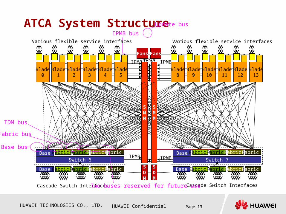
ATCA System StructureIPMB bus
Blade0
Blade1
Blade2
Blade3
Blade4
Blade5
Blade8
Blade9
Blade10
Blade11
Blade12
Blade13
Switch 6
Base Fabric 0Fabric 1Fabric 2Fabric 3
Switch 7
Base Fabric 0Fabric 1Fabric 2Fabric 3
SMM
SMM
Fans
Cascade Switch Interfaces
SMM
Various flexible service interfaces
Base Fabric 0Fabric 1Fabric 2Fabric 3 Fabric 0Fabric 1Fabric 2Fabric 3BaseSDM
SDM
IPMB IPMB
IPMBIPMB
Cascade Switch Interfaces
Various flexible service interfaces
Fans
Base bus
Fabric bus
TDM bus
Two buses reserved for future use
Update bus
HUAWEI TECHNOLOGIES CO., LTD. HUAWEI Confidential Page 14
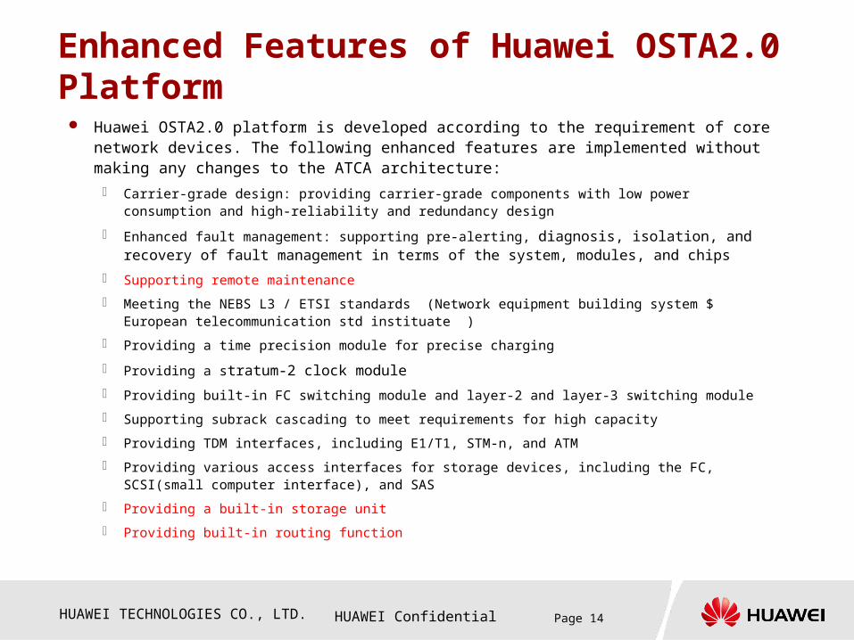
Enhanced Features of Huawei OSTA2.0 Platform
Huawei OSTA2.0 platform is developed according to the requirement of core network devices. The following enhanced features are implemented without making any changes to the ATCA architecture:
Carrier-grade design: providing carrier-grade components with low power consumption and high-reliability and redundancy design
Enhanced fault management: supporting pre-alerting, diagnosis, isolation, and recovery of fault management in terms of the system, modules, and chips
Supporting remote maintenance
Meeting the NEBS L3 / ETSI standards (Network equipment building system $ European telecommunication std instituate )
Providing a time precision module for precise charging
Providing a stratum-2 clock module
Providing built-in FC switching module and layer-2 and layer-3 switching module
Supporting subrack cascading to meet requirements for high capacity
Providing TDM interfaces, including E1/T1, STM-n, and ATM
Providing various access interfaces for storage devices, including the FC, SCSI(small computer interface), and SAS
Providing a built-in storage unit
Providing built-in routing function
HUAWEI TECHNOLOGIES CO., LTD. HUAWEI Confidential Page 15
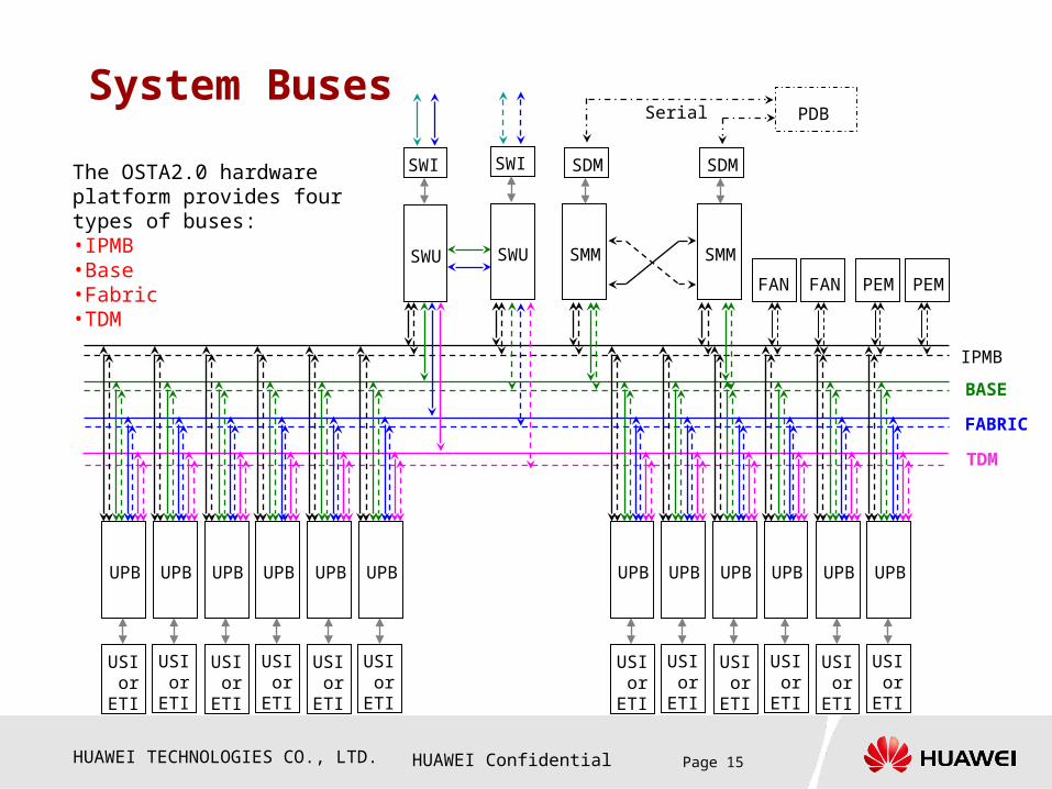
System Buses
The OSTA2.0 hardware platform provides four types of buses:•IPMB•Base•Fabric•TDM
SMM
SDM
SMM
SDM
FAN FAN
PDBSerial
IPMB
BASE
FABRIC
SWU
SWI
SWU
SWI
TDM
UPB UPB UPB UPB UPB UPB UPB UPB UPB UPB UPB UPB
PEMPEM
USI orETI
USI orETI
USI orETI
USI orETI
USI orETI
USI orETI
USI orETI
USI orETI
USI orETI
USI orETI
USI orETI
USI orETI

HUAWEI TECHNOLOGIES CO., LTD. HUAWEI Confidential Page 16
Description of System Buses
The OSTA2.0 hardware platform provides four types of buses:
IPMB bus: It is the device management bus in an OSTA2.0 subrack. With the
IPMB bus, the SMM monitors and manages all the hardware in the subrack. The
IPMB bus transmits all the information related to the hardware, such as alarms,
power-on/power-off operations, and fan speed adjustment.
Base bus: It is located on the management and control plane of the system. It
provides a channel for software loading, alarm reporting, and maintenance
message delivery.
Fabric bus: It provides a data channel for the system service plane. It transmits
the service information of the system.
TDM bus: It is used to deliver the system clock source and the narrowband
timeslot information of bearer boards.

HUAWEI TECHNOLOGIES CO., LTD. HUAWEI Confidential Page 17
Questions
Compared with the OSTA1.0 platform, what are
advantages of the OSTA2.0 platform?
How many types of buses are provided by the
MSOFTX3000 OSTA2.0 platform? What are the
corresponding functions of each type of bus?

HUAWEI TECHNOLOGIES CO., LTD. HUAWEI Confidential Page 18
AnswersCompared with the OSTA1.0 platform, what are advantages of the OSTA2.0 platform?1.Strong scalability, great bandwidth, high integrity, and abundant service interfaces
2.Dual-star bus and distributed power supply ensure higher security.
3.Compliance with standard specifications; lower lifecycle costs
How many types of buses are provided by the MSOFTX3000 OSTA2.0 platform? What are the corresponding functions of each type of bus? The OSTA2.0 hardware system provides four types of buses:
1.IPMB bus: It is the device management bus in the OSTA 2.0 subrack. With the IPMA bus, the SMM monitors and manages all the hardware in the subrack.
2.BASE bus: It is a management control plane bus of the system. It is g generally used for software loading, and transmission of the alarm and maintenance information.
3.FABRIC bus: It is the data channel of the service plane. It is generally used to transmit information related to services in the system.
4.TDM bus: It is used to transmit the information about the system synchronization clock and narrowband timeslots among bearer boards.
HUAWEI TECHNOLOGIES CO., LTD. HUAWEI Confidential Page 19
Contents
Chapter 1 Overview
Chapter 2 Overall System
Chapter 3 Boards
Chapter 4 Signal Flow
Chapter 5 Cable Connection
HUAWEI TECHNOLOGIES CO., LTD. HUAWEI Confidential Page 20
Chapter 2 Overall System
Section 1 Cabinet
Section 2 Subrack
Section 3 PDB
Section 4 MRMU

HUAWEI TECHNOLOGIES CO., LTD. HUAWEI Confidential Page 21
Cabinet
The MSOFTX3000 uses the N68E-22 cabinet:
Dimensions: 600 x 800 x 2200 (width x depth x
height)
Available space inside: 46 U (1 U = 44.45 mm )
A maximum of three OSTA2.0 subracks
configured for each subrack
Weight: 100 kg (400 kg in full configuration)
Single-door providing the air filter, with the
perforated rate reaching 51%
Supporting up to 8 KW heat dissipation
HUAWEI TECHNOLOGIES CO., LTD. HUAWEI Confidential Page 22
Cabinet Configuration
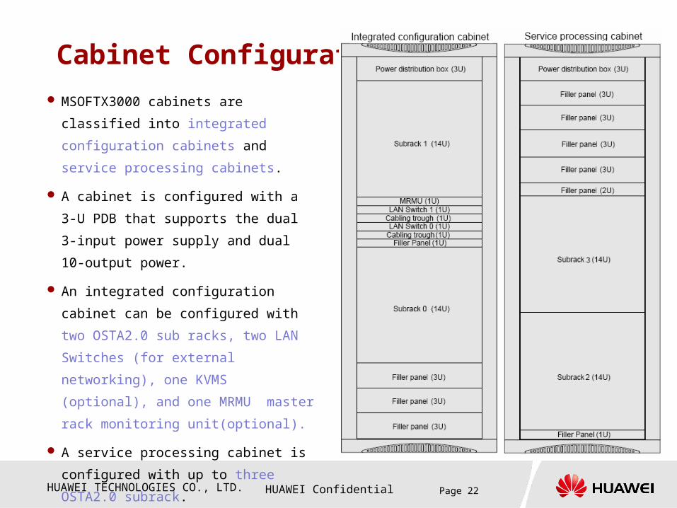
MSOFTX3000 cabinets are classified into
integrated configuration cabinets and
service processing cabinets.
A cabinet is configured with a 3-U PDB that
supports the dual 3-input power supply and
dual 10-output power.
An integrated configuration cabinet can be
configured with two OSTA2.0 sub racks, two
LAN Switches (for external networking), one
KVMS (optional), and one MRMU master
rack monitoring unit(optional).
A service processing cabinet is configured
with up to three OSTA2.0 subrack.
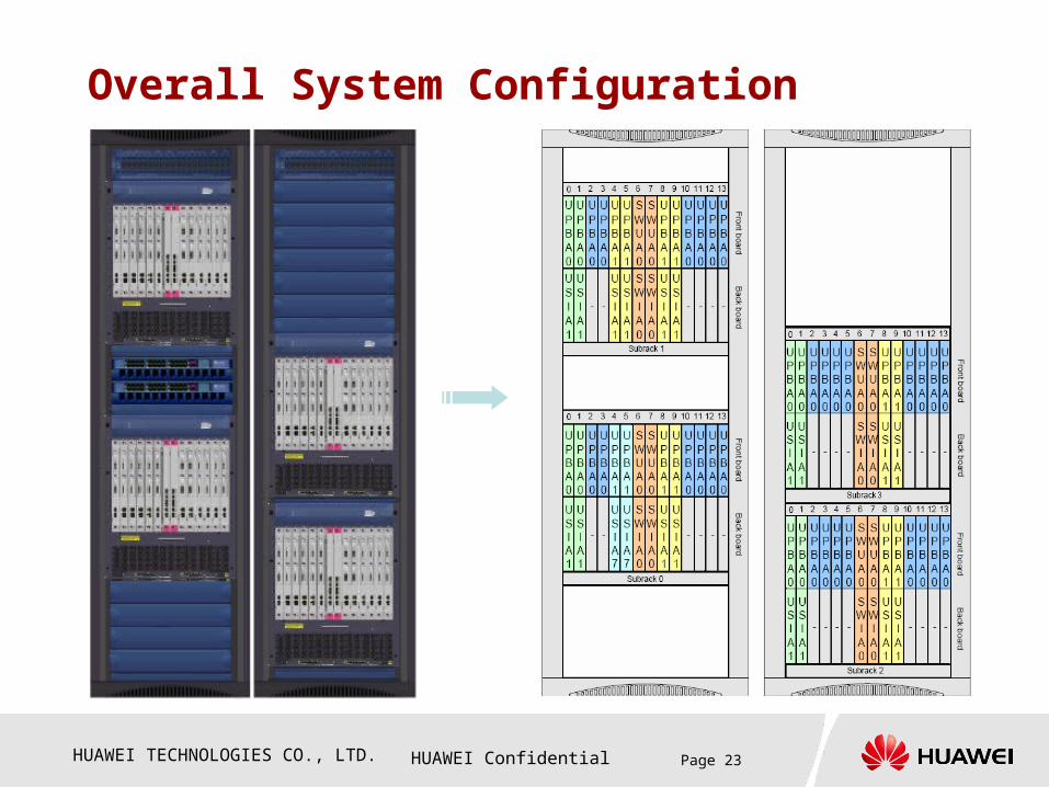
MSOFTX3000 V2R8 supports two cabinet
and four subracks in full configuration, as
shown in the figure.
HUAWEI TECHNOLOGIES CO., LTD. HUAWEI Confidential Page 23
Overall System Configuration

HUAWEI TECHNOLOGIES CO., LTD. HUAWEI Confidential Page 24
Chapter 2 Overall System
Section 1 Cabinet
Section 2 Subrack
Section 3 PDB
Section 4 MRMU

HUAWEI TECHNOLOGIES CO., LTD. HUAWEI Confidential Page 25
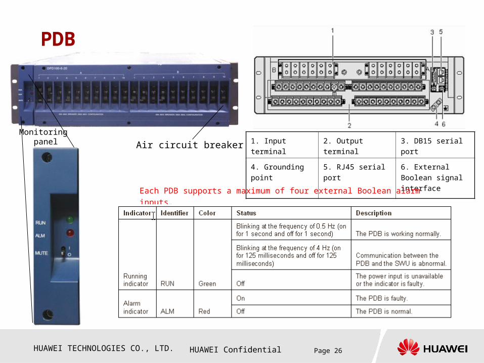
PDB
Supporting dual-input, dual 2-input, and dual 3-
input power supply (dual 3-input is used for the
MSOFTX3000)
Input voltage: -40 to -72 V DC; Maximum input
current: 100 A
Supporting the dual 10-output power supply,
with maximum current of 50 A for each output
(not more than 100 A for each zone)
HUAWEI TECHNOLOGIES CO., LTD. HUAWEI Confidential Page 26
PDB
1. Input terminal 2. Output terminal 3. DB15 serial port
4. Grounding point 5. RJ45 serial port 6. External Boolean
signal interface
Monitoring panel Air circuit breaker
Each PDB supports a maximum of four external Boolean alarm inputs.
HUAWEI TECHNOLOGIES CO., LTD. HUAWEI Confidential Page 27
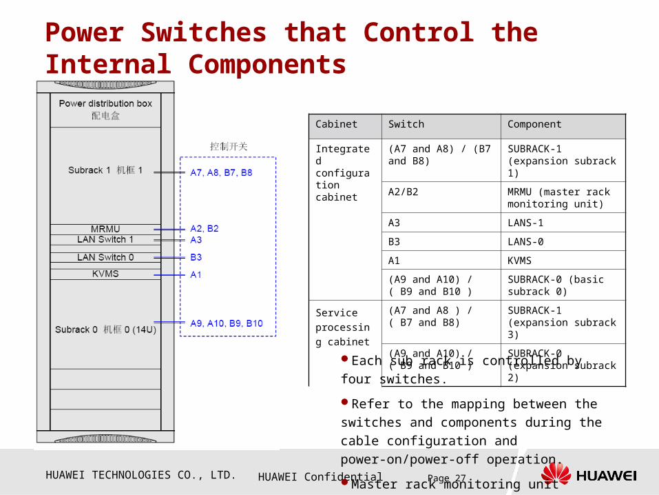
Power Switches that Control the Internal Components
Cabinet Switch Component
Integrated configuration cabinet
(A7 and A8) / (B7 and B8)
SUBRACK-1 (expansion subrack 1)
A2/B2 MRMU (master rack monitoring unit)
A3 LANS-1
B3 LANS-0
A1 KVMS
(A9 and A10) / ( B9 and B10 )
SUBRACK-0 (basic subrack 0)
Service
processing
cabinet
(A7 and A8 ) / ( B7 and B8)
SUBRACK-1 (expansion subrack 3)
(A9 and A10) / ( B9 and B10 )
SUBRACK-0 (expansion subrack 2)
Each sub rack is controlled by four switches.
Refer to the mapping between the switches
and components during the cable configuration
and power-on/power-off operation.
Master rack monitoring unit

HUAWEI TECHNOLOGIES CO., LTD. HUAWEI Confidential Page 28
Chapter 2 Overall System
Section 1 Cabinet
Section 2 PDB
Section 3 Subrack
Section 4 MRMU
HUAWEI TECHNOLOGIES CO., LTD. HUAWEI Confidential Page 29
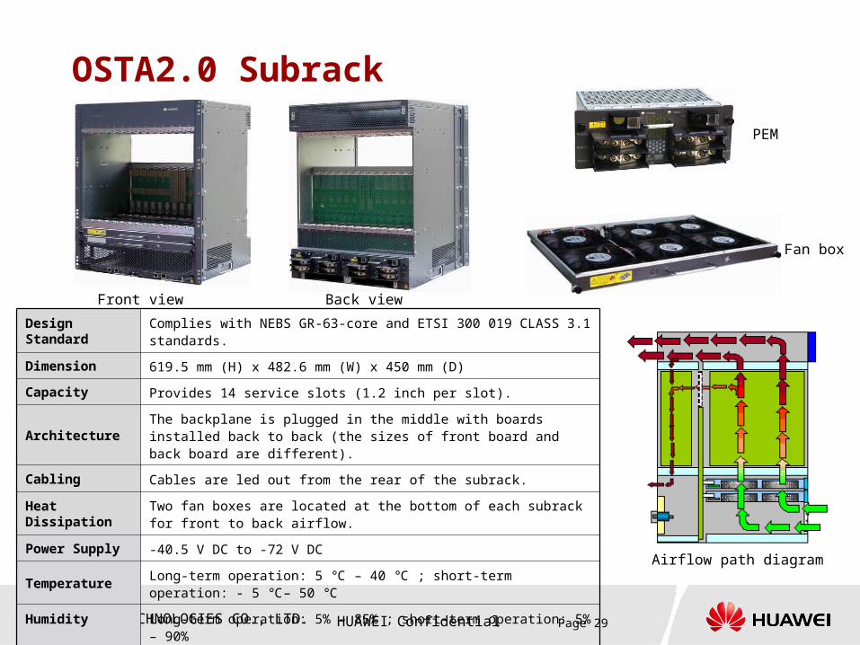
OSTA2.0 Subrack
Design Standard Complies with NEBS GR-63-core and ETSI 300 019 CLASS 3.1 standards.
Dimension 619.5 mm (H) x 482.6 mm (W) x 450 mm (D)
Capacity Provides 14 service slots (1.2 inch per slot).
ArchitectureThe backplane is plugged in the middle with boards installed back to back (the sizes of front board and back board are different).
Cabling Cables are led out from the rear of the subrack.
Heat DissipationTwo fan boxes are located at the bottom of each subrack for front to back airflow.
Power Supply -40.5 V DC to -72 V DC
Temperature Long-term operation: 5 – 40 ; short-term operation: - 5 – 50 ℃ ℃ ℃ ℃
HumidityLong-term operation: 5% – 85% ; short-term operation: 5% – 90%
Fan box
Airflow path diagram
PEM
Front view Back view
HUAWEI TECHNOLOGIES CO., LTD. HUAWEI Confidential Page 30
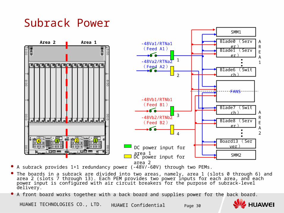
Subrack Power
A subrack provides 1+1 redundancy power (-48V/-60V) through two PEMs. The boards in a subrack are divided into two areas, namely, area 1 (slots 0 through 6) and area 2 (slots 7 through 13). Each
PEM provides two power inputs for each area, and each power input is configured with air circuit breakers for the purpose of subrack-level delivery.
A front board works together with a back board and supplies power for the back board.
13 24
Area 1Area 2
DC power input for area 2
Blade0 ( Server)
Blade1 ( Server)
Blade6 ( Switch)
Blade7 ( Switch)
Blade8 ( Server)
Board13 ( Server)
AREA1
-48Va1/RTNa1( Feed A1)
-48Vb1/RTNb1( Feed B1)
-48Va2/RTNa2( Feed A2)
DC power input for area 1
SMM1
SMM2
FANS
-48Vb2/RTNb2( Feed B2)
4
1
2
3AREA2
HUAWEI TECHNOLOGIES CO., LTD. HUAWEI Confidential Page 31
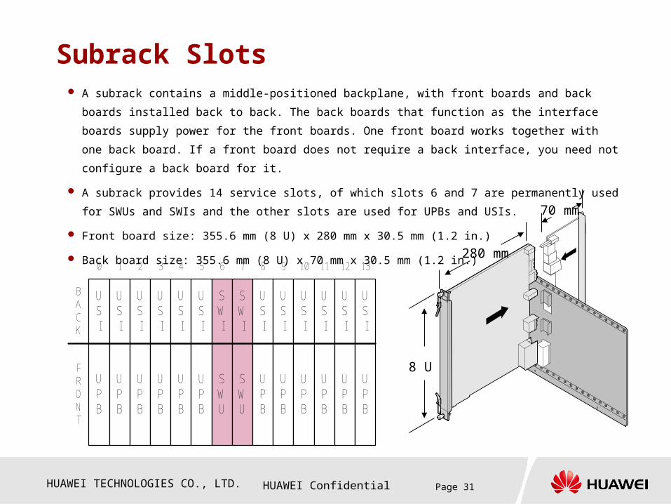
Subrack Slots A subrack contains a middle-positioned backplane, with front boards and back boards installed back to back.
The back boards that function as the interface boards supply power for the front boards. One front board
works together with one back board. If a front board does not require a back interface, you need not
configure a back board for it.
A subrack provides 14 service slots, of which slots 6 and 7 are permanently used for SWUs and SWIs and
the other slots are used for UPBs and USIs.
Front board size: 355.6 mm (8 U) x 280 mm x 30.5 mm (1.2 in.)
Back board size: 355.6 mm (8 U) x 70 mm x 30.5 mm (1.2 in.)
8 U
280 mm
70 mm
UPB
USI
0
UPB
USI
1
UPB
USI
2
UPB
USI
3
UPB
USI
4
UPB
USI
5
SWU
SWI
6
SWU
SWI
7
UPB
USI
8
UPB
USI
9
UPB
USI
10
UPB
USI
11
BACK
FRONT
UPB
USI
12
UPB
USI
13
HUAWEI TECHNOLOGIES CO., LTD. HUAWEI Confidential Page 32
Board Configuration Samples0 1 2 3 4 5 6 7 8 9 10 11
BACK
FRONT
12 13
UPBA0
SWUA1
SWIA1
SWIA1
USIA1
UPBA0
USIA1
UPBA0
UPBA0
UPBA1
UPBA1
UPBA1
UPBA1
UPBA0
UPBA0
UPBA0
UPBA0
SWUA1
USIA7
USIA7
USIA1
USIA1
0 1 2 3 4 5 6 7 8 9 10 11
BACK
FRONT
12 13
UPBA0
SWUA0
SWIA0
SWIA0
USIA1
UPBA0
USIA1
UPBA0
UPBA0
UPBA1
UPBA1
UPBA1
UPBA1
UPBA0
UPBA0
UPBA0
UPBA0
SWUA0
USIA1
USIA1
USIA1
USIA1
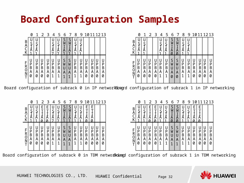
Board configuration of subrack 0 in IP networking Board configuration of subrack 1 in IP networking
Board configuration of subrack 0 in TDM networking
0 1 2 3 4 5 6 7 8 9 10 11
BACK
FRONT
12 13
UPBA0
SWUA1
SWIA1
SWIA1
USIA1
UPBA0
USIA1
UPBA0
UPBA0
UPBA1
UPBA1
UPBA1
UPBA1
UPBA0
UPBA0
UPBA0
UPBA0
SWUA1
USIA7
USIA7
USIA1
USIA1
ETIA0
ETIA0
ETIA0
ETIA0
0 1 2 3 4 5 6 7 8 9 10 11
BACK
FRONT
12 13
UPBA0
SWUA1
SWIA0
SWIA0
USIA1
UPBA0
USIA1
UPBA0
UPBA0
UPBA1
UPBA1
UPBA1
UPBA1
UPBA0
UPBA0
UPBA0
UPBA0
SWUA1
USIA1
USIA1
USIA1
USIA1
Board configuration of subrack 1 in TDM networking
ETIA0
ETIA0
ETIA0
ETIA0
HUAWEI TECHNOLOGIES CO., LTD. HUAWEI Confidential Page 33
Chapter 2 Overall System
Section 1 Cabinet
Section 2 Subrack
Section 3 PDB
Section 4 MRMU
HUAWEI TECHNOLOGIES CO., LTD. HUAWEI Confidential Page 34
MRMU
SN. Description
1 Power ports
2 Detecting/control ports
3 Smoke sensor reset button
4 Serial communication ports
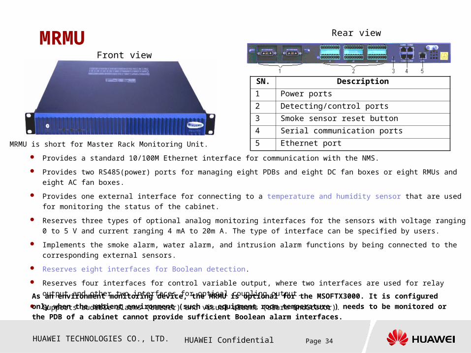
5 Ethernet portMRMU is short for Master Rack Monitoring Unit.
Provides a standard 10/100M Ethernet interface for communication with the NMS.
Provides two RS485(power) ports for managing eight PDBs and eight DC fan boxes or eight RMUs and eight AC fan boxes.
Provides one external interface for connecting to a temperature and humidity sensor that are used for monitoring the status of the
cabinet.
Reserves three types of optional analog monitoring interfaces for the sensors with voltage ranging 0 to 5 V and current ranging 4 mA
to 20m A. The type of interface can be specified by users.
Implements the smoke alarm, water alarm, and intrusion alarm functions by being connected to the corresponding external sensors.
Reserves eight interfaces for Boolean detection.
Reserves four interfaces for control variable output, where two interfaces are used for relay output and other two interfaces for
optical coupling output.
Supports audible alarms (buzzer) and visual alarms (alarm indicator).
Front view
Rear view
As an environment monitoring device, the MRMU is optional for the MSOFTX3000. It is configured only when the ambient
environment (such as equipment room temperature ) needs to be monitored or the PDB of a cabinet cannot provide
sufficient Boolean alarm interfaces.
HUAWEI TECHNOLOGIES CO., LTD. HUAWEI Confidential Page 35
Questions
Which type of cabinet is used for the MSOFTX3000? How many types of cabinets are
there?
Integrated configuration cabinet & service processing cabinet
How many cabinets and sub racks are supported by the MSOFTX3000 in full
configuration?
2 cabinet & 4 sub racks
How many slots are provided by an OSTA2.0 sub rack of the MSOFTX3000? How many
slots are service slots?
14 are service slots
What are the power supply features of an OSTA2.0 sub rack of the MSOFTX3000?
Dual 3 input and 10 out puts power supplies
HUAWEI TECHNOLOGIES CO., LTD. HUAWEI Confidential Page 36
Answers
Which type of cabinet is used for the MSOFTX3000? How many types of cabinets are there?
The N68E-22 cabinet is used for the MSOFTX3000 . There are two types of cabinets. They are integrated configuration cabinet and service processing cabinet.
How many cabinets and subracks are supported by the MSOFTX3000 in full configuration?
Two cabinets and four subracks are supported by MSOFTX3000 in full configuration.
How many slots are provided by an OSTA2.0 subrack of the MSOFTX3000? How many slots are service slots?
A total of 14 slots are provided by an OSTA subrack. Among them, 12 slots are used as service slots.
What are the power supply features of an OSTA2.0 subrack of the MSOFTX3000?
An OSTA2.0 subrack supports area-based power supply and 1+1 redundancy power bus. The subrack provides two PEMs to implement 1+1 power supply. The boards in the subrack are divided into two areas. One area covers slots 0 through 6 and the other area covers slots 7 through 13. Each PEM provides two power inputs and each power input is responsible for each area
HUAWEI TECHNOLOGIES CO., LTD. HUAWEI Confidential Page 37
Contents
Chapter 1 Overview
Chapter 2 Overall System
Chapter 3 Boards
Chapter 4 Signal Flow
Chapter 5 Cable Connection

HUAWEI TECHNOLOGIES CO., LTD. HUAWEI Confidential Page 38
Chapter 3 Boards
Section 1 General Introduction
Section 2 Device Management
Module
Section 3 Switching Module
Section 4 Service Processing
Module

HUAWEI TECHNOLOGIES CO., LTD. HUAWEI Confidential Page 39
System Interconnection The MSOFTX3000 hardware is
composed of main components
and auxiliary components.
The main components are
composed of OSTA2.0
subracks, which work in self-
cascading mode.
In the ATCA platform, the
functionalities of the BAM,
iGWB, and XPTU are
implemented by boards and
integrated in a subrack. The
XPTU is deployed as a process
in the OMU board.
In the SOSM networking,
independent servers are
adopted for the BAM, iGWB,
and XPTU in a cabinet.
UPB
UPB
UPB
UPB
LMT
To the IP Backbone network
SMM
SWU
SWU
UPB
UPB
OMU
OMU
UPB
UPB
UPB
UPB
IGWB
IGWBSMM
SMM
SWU
SWU
UPB
UPB
UPB
IGWB
IGWB
UPB
UPB
UPB
UPB
UPB
UPB
UPB
SMM
SMM
SWU
SWU
UPB
UPB
UPB
IGWB
IGWB
UPB
UPB
UPB
UPB
UPB
SMM
0#
1#
2#
To the billing centerTo the billing Center
LMT LMT
To the network management center
LANSWITCH
HUB
To the NTP ServerTo the NTP Server
Host
To the IP Backbone network
To the billing CenterTo the billing Center
HUAWEI TECHNOLOGIES CO., LTD. HUAWEI Confidential Page 40
OSTA2.0 Logical Structure
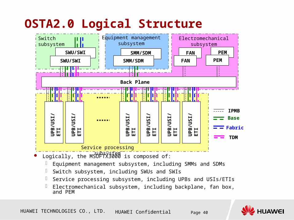
Logically, the MSOFTX3000 is composed of: Equipment management subsystem, including SMMs and SDMs Switch subsystem, including SWUs and SWIs Service processing subsystem, including UPBs and USIs/ETIs Electromechanical subsystem, including backplane, fan box, and PEM
Back Plane
Service processing subsystem
SMM/SDM
Equipment managementsubsystem
Switch subsystem
IPMB
Base
Fabric
SWU/SWI SMM/SDM
SWU/SWI
Electromechanical subsystem
FAN
FAN
PEM
PEM
UP
B/U
SI/
ET
I
TDM
UP
B/U
SI/
ET
I
UP
B/U
SI/
ET
I
UP
B/U
SI/
ET
I
UP
B/U
SI/
ET
I
UP
B/U
SI/
ET
I
HUAWEI TECHNOLOGIES CO., LTD. HUAWEI Confidential Page 41
Chapter 3 Boards
Section 1 General Introduction
Section 2 Device Management
Module
Section 3 Switching Module
Section 4 Service Processing
Module
HUAWEI TECHNOLOGIES CO., LTD. HUAWEI Confidential Page 42
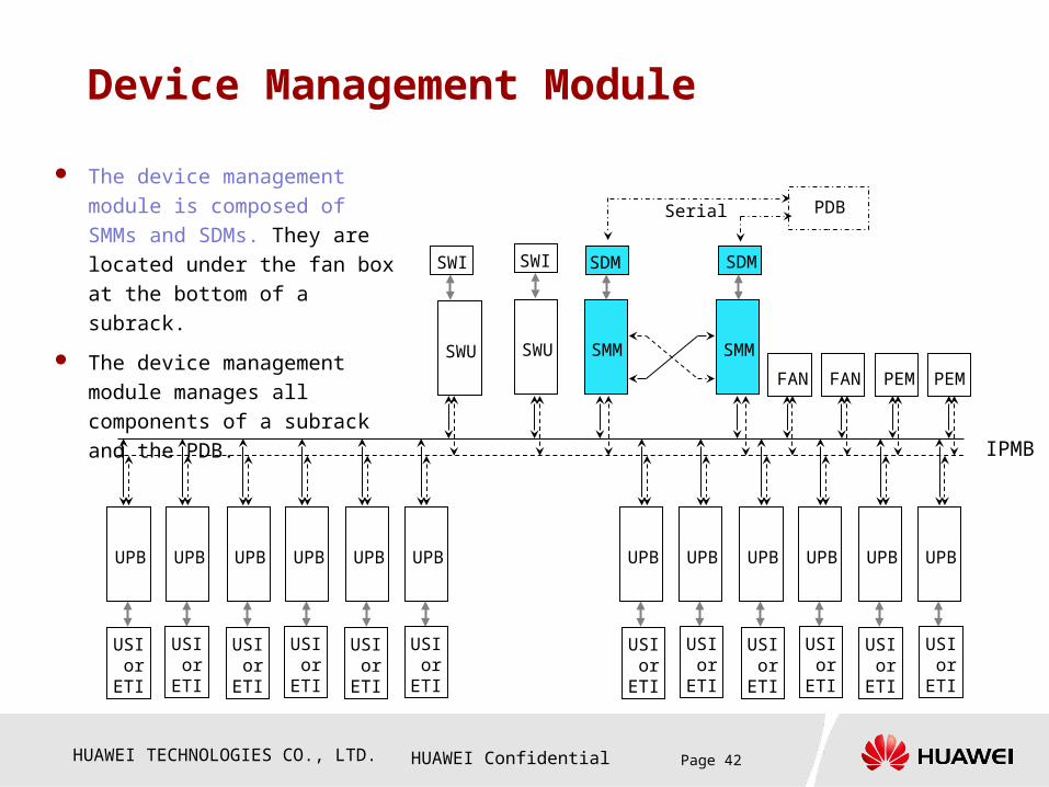
Device Management Module
The device management module
is composed of SMMs and SDMs.
They are located under the fan
box at the bottom of a subrack.
The device management module
manages all components of a
subrack and the PDB.SMM
SDM
SMM
SDM
FAN FAN
PDBSerial
UPB
USI orETI
UPB UPB UPB UPB UPB UPB UPB UPB UPB UPB UPB
SWU
SWI
SWU
SWI
IPMB
PEM PEM
USI orETI
USI orETI
USI orETI
USI orETI
USI orETI
USI orETI
USI orETI
USI orETI
USI orETI
USI orETI
USI orETI
HUAWEI TECHNOLOGIES CO., LTD. HUAWEI Confidential Page 43
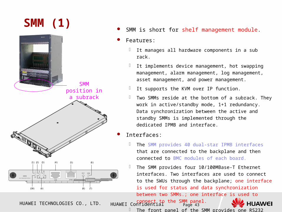
SMM (1) SMM is short for shelf management module.
Features:
It manages all hardware components in a sub rack.
It implements device management, hot swapping management,
alarm management, log management, asset management, and
power management.
It supports the KVM over IP function.
Two SMMs reside at the bottom of a subrack. They work in
active/standby mode, 1+1 redundancy. Data synchronization
between the active and standby SMMs is implemented through
the dedicated IPMB and interface.
Interfaces:
The SMM provides 40 dual-star IPMB interfaces that are
connected to the backplane and then connected to BMC
modules of each board.
The SMM provides four 10/100MBase-T Ethernet interfaces.
Two interfaces are used to connect to the SWUs through the
backplane; one interface is used for status and data
synchronization between two SMMs.; one interface is used to
connect to the SMM panel.
The front panel of the SMM provides one RS232 serial port.
COM ETH0
RST HSW
SMMD
SHELF MANAGEMENT MODULE
(1) (2) (3) (4) (5) (6)
(10) (9) (8) (7)
SMM position in a subrack

HUAWEI TECHNOLOGIES CO., LTD. HUAWEI Confidential Page 44
SMM (2)
COM ETH0
RST HSW
SMMD
SHELF MANAGEMENT MODULE
(1) (2) (3) (4) (5) (6)
(10) (9) (8) (7)
1: Minor alarm indicator
2: Major alarm indicator
3: Critical alarm indicator
4: COM serial port
5: ETH0 interface
6: HOTSWAP indicator
7: Ejector lever
8: Reset button
9: Customized indicators
10: HEALTHY indicator
Indicator Color Meaning Description Normal State
HEALTHYRed or green
Healthy status
indicator
The HEALTHY indicator has four states:•Off: The SMM is not installed or powered on.•Steady green: The SMM works normally.•Flash green (at the frequency of 0.5 Hz): The SMM is in the standby state.•Steady red: The software is not started, or a hardware failure occurs.
Steady green
HOTSWAP BlueHot-
swapping indicator
The HOTSWAP indicator has four states:•Off: The SMM is running or is in the active state.•On: The SMM is powered off or the SMM is loading processes.•Fast blink: The SMM is being activated.•Slow blink: The SMM is being deactivated.
Off
Alarm indicator
Red
Minor,major, and
criticalalarm
indicators
The meanings of the three alarmindicators are as follows:•!: A minor alarm is generated.•!!: A major alarm is generated.•!!!: A critical alarm is generated.
Off
Customized indicator
Red or green
Customizedindicator
You can define the state and meaning of this indicator. -
Fast blink means that the indicator is on for 900 ms and off for 100 ms alternatively. Slow blink means that the indicator is on for 100 ms and off for 900 ms alternatively.
HUAWEI TECHNOLOGIES CO., LTD. HUAWEI Confidential Page 45
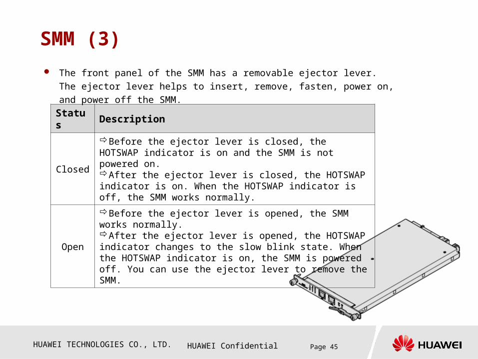
SMM (3)
Status Description
Closed
Before the ejector lever is closed, the HOTSWAP indicator is on and the SMM is not powered on.After the ejector lever is closed, the HOTSWAP indicator is on. When the HOTSWAP indicator is off, the SMM works normally.
Open
Before the ejector lever is opened, the SMM works normally.After the ejector lever is opened, the HOTSWAP indicator changes to the slow blink state. When the HOTSWAP indicator is on, the SMM is powered off. You can use the ejector lever to remove the SMM.
The front panel of the SMM has a removable ejector lever. The ejector lever
helps to insert, remove, fasten, power on, and power off the SMM.
HUAWEI TECHNOLOGIES CO., LTD. HUAWEI Confidential Page 46
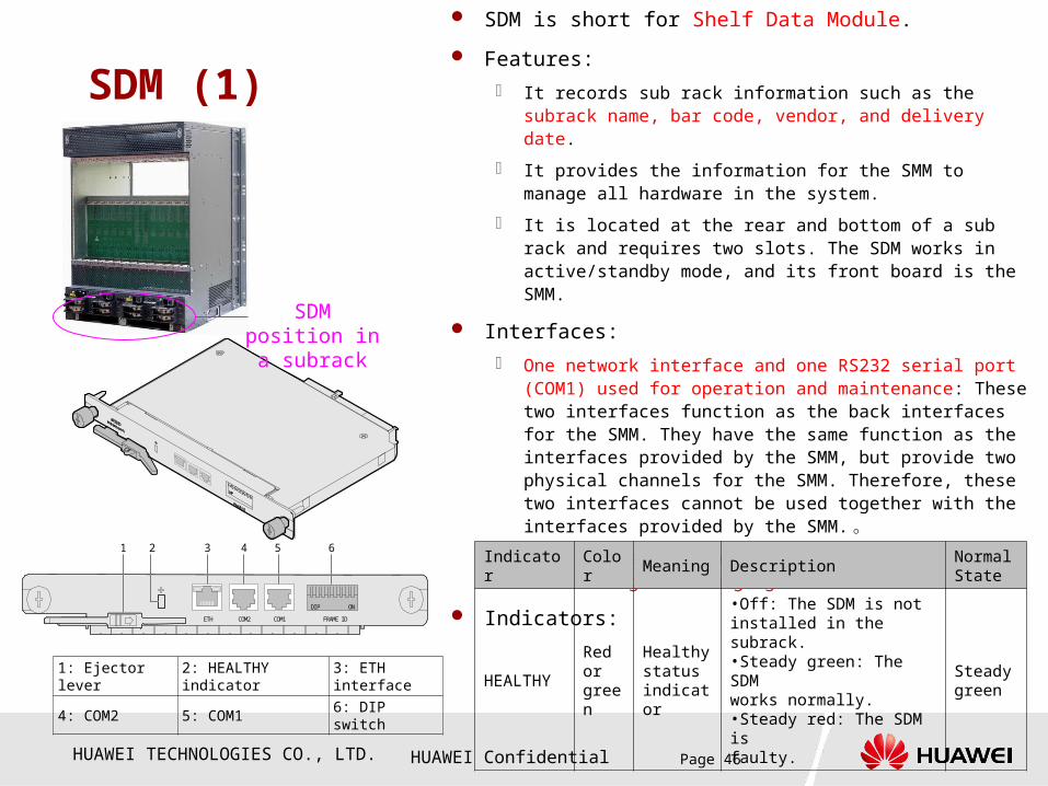
SDM (1)
1: Ejector lever 2: HEALTHY indicator 3: ETH interface
4: COM2 5: COM1 6: DIP switch
SDM is short for Shelf Data Module.
Features:
It records sub rack information such as the subrack name, bar code, vendor, and delivery date.
It provides the information for the SMM to manage all hardware in the system.
It is located at the rear and bottom of a sub rack and requires two slots. The SDM works in active/standby mode, and its front board is the SMM.
Interfaces:
One network interface and one RS232 serial port (COM1) used for operation and maintenance: These two interfaces function as the back interfaces for the SMM. They have the same function as the interfaces provided by the SMM, but provide two physical channels for the SMM. Therefore, these two interfaces cannot be used together with the interfaces provided by the SMM. 。
One RS485 serial port (COM2) used for maintaining and managing the PDB.
Indicators:1 2 3 4 6
COM2ETH COM1 FRAME I D
DI P ON
5
SDM position in a subrack
Indicator Color Meaning DescriptionNormal State
HEALTHY Red or green
Healthy status indicator
•Off: The SDM is notinstalled in the subrack.•Steady green: The SDMworks normally.•Steady red: The SDM isfaulty.
Steady green
HUAWEI TECHNOLOGIES CO., LTD. HUAWEI Confidential Page 47
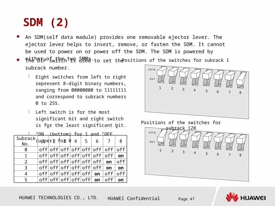
SDM (2) An SDM(self data madule) provides one removable ejector lever. The ejector lever helps to
insert, remove, or fasten the SDM. It cannot be used to power on or power off the SDM. The
SDM is powered by either of the two SMMs.
The DIP switch is used to set the subrack
number.
Eight switches from left to right represent 8-
digit binary numbers, ranging from 00000000
to 11111111 and correspond to subrack
numbers 0 to 255.
Left switch is for the most significant bit and
right switch is for the least significant bit.
“ON” (bottom) for 1 and “OFF” (upper) for 0
1 2 3 4 5 6 7 8
ON:1
OFF:0
1 2 3 4 5 6 7 8
ON:1
OFF:0
Positions of the switches for subrack 1
Positions of the switches for subrack 128
Subrack No.
1 2 3 4 5 6 7 8
0 off off off off off off off off1 off off off off off off off on2 off off off off off off on off3 off off off off off off on on4 off off off off off on off off5 off off off off off on off on

HUAWEI TECHNOLOGIES CO., LTD. HUAWEI Confidential Page 48
Chapter 3 Boards
Section 1 General Introduction
Section 2 Device Management
Module
Section 3 Switching Module
Section 4 Service Processing
Module

HUAWEI TECHNOLOGIES CO., LTD. HUAWEI Confidential Page 49
Switch Module A switching module is composed of SWUs and SWIs, which
are located in slots 6 and 7.
The SWUs provide switching functions through the BASE
plane, Fabric GE plane, and TDM plane.
The SWIs provide external interfaces for implementing
cascading of the BASE plane and Fabric GE plane.
The cascading of the TDM platform is implemented through
the Base plane. 1. first & salve 2 types
SWI
SMM
SDM
BASEFABRIC
SWU
SWI
SWU SMM
SDM
TDM
UPB
USI orETI
UPB UPB UPB UPB UPB UPB UPB UPB UPB UPB UPB
USI orETI
USI orETI
USI orETI
USI orETI
USI orETI
USI orETI
USI orETI
USI orETI
USI orETI
USI orETI
USI orETI
UPB
UPB
UPB
UPB
UPB
UPB
SWU
SWU
UPB
UPB
UPB
UPB
UPB
UPB
USI
USI
USI
USI
USI
USI
SWI
SWI
USI
USI
USI
USI
USI
USI
0 1 2 3 4 5 6 7 8 9 10111213
FRONT
BACKBackplane

HUAWEI TECHNOLOGIES CO., LTD. HUAWEI Confidential Page 50
SWU (1)
1. Ejector lever 2. OOS indicator
3. HEALTHY indicator 4. SYSTEM indicator
5. BMC COM serial port
6. SYS COM serial port
7. LAN0 port 8. HOTSWAP indicator
9. LAN1 port
SWU is short for Switch Unit. Features:
The SWU implements data switching among the boards in a sub rack through the backplane and data switching among sub racks through cascading interfaces provided by the SWIs.
Three planes: Base, Fabric, and TDM Base plane:
− Provides 12 interfaces for connecting to 12 UPB slots.− Provides two interfaces for connecting to the active and standby
SMMs.− Provides one interface for connecting to the Base plane of the
other SWU to implement redundancy of the Base plane.− Provides eight external interfaces provided by the SWIs.
Fabric plane:− Provides 12 interfaces for connecting to 12 UPB slots.− Provides one interface for connecting to the Fabric plane of the
other SWU to implement redundancy of the Fabric plane.− Provides eight external interfaces provided by the SWIs.
TDM plane:− Provides 12 interfaces for connecting to 12 UPB slots.− Provides eight cascading interfaces and sharing external.
interfaces with the Base plane to implement cascading among sub racks.
− Implements the distribution of the system synchronization clocks and interworking of the TDM service messages.

HUAWEI TECHNOLOGIES CO., LTD. HUAWEI Confidential Page 51
SWU (2)
SWU0 SWU1
1 GE Fabric Switch daughter Card
2 TDM Switch daughter Card
Currently, the MSOFTX3000 provides two types of the SWU, that is, SWU0 and SWU1.
The SWU0 provides switching functions only through the Base plane and GE Fabric plane. It is
used for broadband networking.
Based on the SWU0, the SWU1 is added with TDM switching functions. It can implement the
clock distribution among sub racks and TDM switching. It is used for narrowband networking.
HUAWEI TECHNOLOGIES CO., LTD. HUAWEI Confidential Page 52
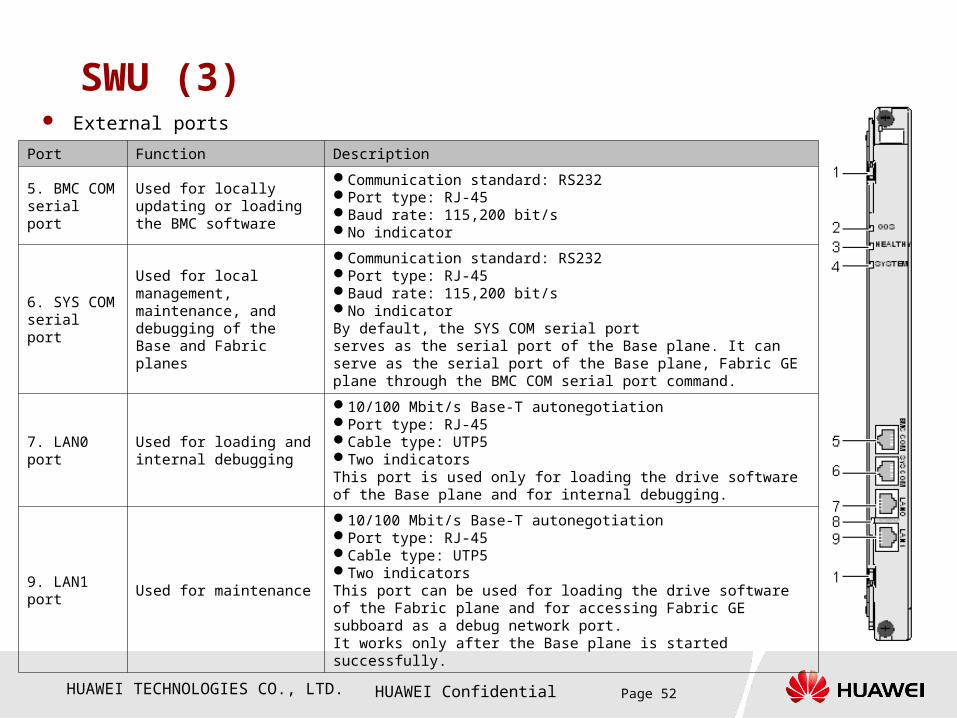
SWU (3) External ports
Port Function Description
5. BMC COM serial port
Used for locally updating or loading the BMC software
Communication standard: RS232Port type: RJ-45Baud rate: 115,200 bit/sNo indicator
6. SYS COM serial port
Used for local management, maintenance, and debugging of the Base and Fabric planes
Communication standard: RS232Port type: RJ-45Baud rate: 115,200 bit/sNo indicatorBy default, the SYS COM serial portserves as the serial port of the Base plane. It can serve as the serial port of the Base plane, Fabric GE plane through the BMC COM serial port command.
7. LAN0 portUsed for loading and internal debugging
10/100 Mbit/s Base-T autonegotiationPort type: RJ-45Cable type: UTP5Two indicatorsThis port is used only for loading the drive software of the Base plane and for internal debugging.
9. LAN1 port Used for maintenance
10/100 Mbit/s Base-T autonegotiationPort type: RJ-45Cable type: UTP5Two indicatorsThis port can be used for loading the drive software of the Fabric plane and for accessing Fabric GE subboard as a debug network port.It works only after the Base plane is started successfully.
HUAWEI TECHNOLOGIES CO., LTD. HUAWEI Confidential Page 53
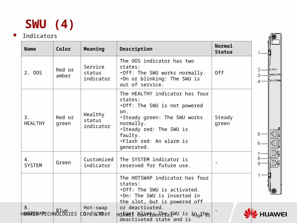
SWU (4) Indicators
Name Color Meaning Description Normal Status
2. OOSRed or amber
Service statusindicator
The OOS indicator has two states:•Off: The SWU works normally.•On or blinking: The SWU is out of service.
Off
3. HEALTHY
Red or green
Healthy statusindicator
The HEALTHY indicator has four states:•Off: The SWU is not powered on.•Steady green: The SWU works normally.•Steady red: The SWU is faulty.•Flash red: An alarm is generated.
Steady green
4. SYSTEM GreenCustomized indicator
The SYSTEM indicator is reserved for future use.
-
8. HOTSWAP
BlueHot-swapindicator
The HOTSWAP indicator has four states:•Off: The SWU is activated.•On: The SWU is inserted in the slot, but is powered off or deactivated.•Fast blink: The SWU is in the deactivated state and is requesting activation.•Slow blink: The SWU is in the activated state and is requesting deactivation.
-

HUAWEI TECHNOLOGIES CO., LTD. HUAWEI Confidential Page 54
SWI (1)
1. Line clock input interface
2. BASE/TDM interface
3. FABRIC interface 4. BITS clock input interface
5. Ejector lever 6. HOTSWAP indicator
7. HEALTHY indicator 8. OSS indicator
SWI is short for Switch Interface Unit.
Features: It is the interface board of the SWU. It is used to connect to
external devices or implement cascading of several subracks.
It provides eight 10/100/1000M Base-T interfaces of the Base plane. These interfaces also used for bearer of TDM services.
It provides eight 10/100/1000M Base-T interfaces of the GE Fabric plane.
It provides stratum-2 or stratum-3 clock functions, supporting BITS clock source and line clock source.
Interfaces:Interface Description
2. BASE/TDM interface
Eight Gigabit Ethernet interfaces10/100/1000 Mbit/s Base-T autonegotiation; Two indicators
3. FABRIC interface Eight Gigabit Ethernet interfaces10/100/1000 Mbit/s Base-T autonegotiation; Two indicators
4. BITS clock input
interface
One SMB interface
Provides 2-Mbps/2-MHz external clock input.
1. Line clock input
interface
One RJ45 interface
Provides two 8k line cock input.
SWIA0 SWIA1

HUAWEI TECHNOLOGIES CO., LTD. HUAWEI Confidential Page 55
SWI (2)
Indicators:
Name Color Meaning DescriptionNormal Status
8. OOSindicator
Red or amber
Service statusindicator
The OOS indicator has two states:•Off: The SWI works normally.•On or blinking: The SWI is out of service. Off
7. HEALTHY indicator
Red or green
Healthy statusindicator
The HEALTHY indicator has four states:•Off: The SWI is not powered on.•Steady green: The SWI works normally.•Steady red: The SWI is faulty.•Flash red: An alarm
Steady green
6. HOTSWAP indicator Blue
Hot-swapindicator
The HOTSWAP indicator has four states:•Off: The SWI is activated.•On: The SWI is inserted in the slot, but is powered off or deactivated.•Fast blink: The SWI is in the deactivated state and is requesting activation.•Slow blink: The SWI is in the activated state and is requesting deactivation. -

HUAWEI TECHNOLOGIES CO., LTD. HUAWEI Confidential Page 56
Chapter 3 Boards
Section 1 General Introduction
Section 2 Device Management
Module
Section 3 Switching Module
Section 4 Service Processing
Module

HUAWEI TECHNOLOGIES CO., LTD. HUAWEI Confidential Page 57
A service processing module is composed of multiple blade servers. A blade server can
be a front board UPB, a back board USI, or a narrowband interface board ETI.
The UPBs, USIs, and ETI are installed in slots 0 through 5 and slots 8 through 13.
The UPB is classified into UPBA0 and UPBA1. The UPBA0 can serve as a service
processing board that is deployed with the CCU, IFM, or BSG process. The UPBA1 can
serve as a server that is deployed with the OMU or iGWB.
The USI is classified into USIA1 and USIA7. The USIA1 provides four GE interfaces and
can serve as an IP interface board or an interface board for the iGWB/XPTU. The USIA7
provides six GE interfaces and one RTC clock module. It can serve as an interface board
for the OMU.
The ETI is classified into ETIA0 and EITA2. The ETIA0 provides 32 E1/T1 interfaces. The
ETIA2 provides 16 E1/T1 interfaces and 2 GE interfaces. The function of the ETI is to
provide narrowband interfaces for the UPBA0s.
Service Processing Module
HUAWEI TECHNOLOGIES CO., LTD. HUAWEI Confidential Page 58
UPB (1)
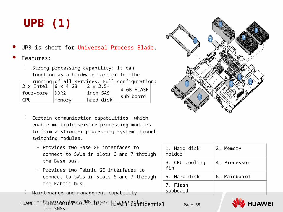
UPB is short for Universal Process Blade.
Features:
Strong processing capability: It can function as a hardware
carrier for the running of all services. Full configuration:
Certain communication capabilities, which enable multiple
service processing modules to form a stronger processing
system through switching modules.
− Provides two Base GE interfaces to connect to SWUs
in slots 6 and 7 through the Base bus.
− Provides two Fabric GE interfaces to connect to
SWUs in slots 6 and 7 through the Fabric bus.
Maintenance and management capability
− Provides two IPMB buses to connect to the SMMs.
− Supports the display, mouse, and keyboard.
1. Hard disk holder 2. Memory
3. CPU cooling fin 4. Processor
5. Hard disk 6. Mainboard
7. Flash subboard
2 x Intel four-
core CPU
6 x 4 GB
DDR2
memory
2 x 2.5-inch
SAS hard disk
4 GB FLASH
sub board
HUAWEI TECHNOLOGIES CO., LTD. HUAWEI Confidential Page 59
UPB universal process bord (2)
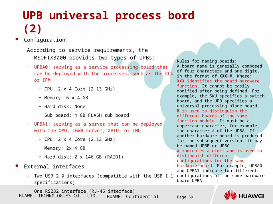
Rules for naming boards:A board name is generally composed of four characters and one digit, in the format of XXXM#. Where:XXX identifies the board hardware function. It cannot be easily modified after being defined. For example, the SWU specifies a switch board, and the UPB specifies a universal processing blade board. M is used to distinguish the different boards of the same function module. It must be a uppercase character, for example, the character A of the UPBA. If another hardware board is produced for the subsequent version, it may be named UPBB or UPBC.# indicates a digit and is used to distinguish different configurations for the same hardware board. For example, UPBA0 and UPBA1 indicate two different configurations of the same hardware board UPBA.
Configuration:
According to service requirements, the MSOFTX3000 provides
two types of UPBs:
UPBA0: serving as a service processing board that can be deployed
with the processes, such as the CCU or IFM
− CPU: 2 x 4 Core (2.13 GHz)
− Memory: 6 x 4 GB
− Hard disk: None
− Sub board: 4 GB FLASH sub board
UPBA1: serving as a server that can be deployed with the OMU,
iGWB server, XPTU, or INU:
− CPU: 2 x 4 Core (2.13 GHz)
− Memory: 2x 4 GB
− Hard disk: 2 x 146 GB (RAID1)
External interfaces:
Two USB 2.0 interfaces (compatible with the USB 1.1 specifications)
One RS232 interface (RJ-45 interface)

HUAWEI TECHNOLOGIES CO., LTD. HUAWEI Confidential Page 60
UPB (3) Indicators:
1. Captive screw 2. Hard disk 1
3. Hard disk 0 4. USB port
5. COM serial port6. HOTSWAP indicator
7. HD0_RAID/ALM indicator
8. HD0_ACT indicator
9. HD1_RAID/ALM indicator
10. HD1_ACT indicator
11. SYSTEM indicator 12. HEALTHY indicator
13. OOS indicator 14. Ejector lever
Name Color Meaning Description
13. OOS indicator
Red or amber
Service status indicator
The OOS indicator can be in red (in north America) or amber (in Europe). The color of the OOS indicator can be set through the BMC command.
Off: The UPB works normally and the services are in progress.
On or blinking: The UPB is out of service.
12. HEALTHY indicator
Red or green
Healthy status indicator
Off: The UPB is not powered on. (The indicator blinks 10 times during power-on.)
Steady green: The UPB works normally.
Blinking red: An alarm occurs in the UPB.
11. SYSTEM indicator
- - You can define the function of this indicator.
6. HOTSWAP indicator
BlueHot-swap indicator
Off: The UPB is activated.On: The UPB is not powered on or is deactivated.Fast blink (The indicator is on for 900 ms and then off for 100 ms alternatively.): The UPB is being activated.Slow blink (The indicator is on for 900 ms and then off for 100 ms alternatively.): The UPB is being deactivated.
8/10. HD_ACT indicator
Green
Hard disk status indicator
The HD_ACT indicator indicates whether the hard disk is activated or being read or written.Off: The hard disk is not installed or is deactivated.On: The hard disk is activated.Blinking: The hard disk is being read or written.
7/9. HD_RAID/ALM indicator
Red or green
Hard disk status indicator
The HD_RAID/ALM indicator indicates whether the hard disk is in RAID synchronization or whether a fault or alarm occurs.Steady red: The hard disk is faulty.Blinking red: The hard disk generates alarms.Blinking green (at a frequency of 1 Hz): The hard disk is in RAID synchronization.

HUAWEI TECHNOLOGIES CO., LTD. HUAWEI Confidential Page 61
USI (1) USI is short for Universal Service Interface.
Features:
As a back board, the USI provides interfaces for the UPB to
communicate with external devices. It must be used together with the
UPB.
The USI can be installed with different sub boards to provide different
interfaces.
Sub boards used by the USI:
− GE sub board: Configure 2 pcs for the USIA1 in the position of
J3 and J2; configure 3 pcs for the USIA7 in the position of J3, J2,
and J1. Each GE subscriber provides two GE interfaces.
− RTC subboard: Configure 1 pcs for the USIA7 in the position of
J4. As the back board of the OMU, the RTC subboard provides
the precise time source.
1. Positioning pin 2. Subboard connector (J4)
3. Subboard connector (J1) 4. Subboard connector (J2)
5. Subboard connector (J3) 6. Subboard positioning hole
网口指示灯
网口指示灯
GE subboard RTC subboard
HUAWEI TECHNOLOGIES CO., LTD. HUAWEI Confidential Page 62
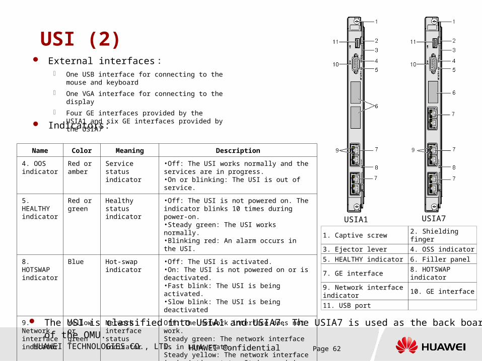
USI (2)
Indicators:
1. Captive screw 2. Shielding finger
3. Ejector lever 4. OSS indicator
5. HEALTHY indicator 6. Filler panel
7. GE interface8. HOTSWAP indicator
9. Network interface indicator
10. GE interface
11. USB port
External interfaces: One USB interface for connecting to the mouse and
keyboard
One VGA interface for connecting to the display
Four GE interfaces provided by the USIA1 and six GE interfaces provided by the USIA7
USIA1 USIA7
The USI is classified into USIA1 and USIA7. The USIA7 is used as the back board of the OMU.
Name Color Meaning Description
4. OOS indicator
Red or amber
Service status indicator
•Off: The USI works normally and the services are in progress.•On or blinking: The USI is out of service.
5. HEALTHY indicator
Red or green
Healthy status indicator
•Off: The USI is not powered on. The indicator blinks 10 times during power-on.•Steady green: The USI works normally.•Blinking red: An alarm occurs in the USI.
8. HOTSWAP indicator
Blue Hot-swap indicator •Off: The USI is activated.
•On: The USI is not powered on or is deactivated.•Fast blink: The USI is being activated.•Slow blink: The USI is being deactivated
9. Network interface indicator
Yellow or green
Network interface status indicator
Off: The network interface does not work.Steady green: The network interface is in Link state.Steady yellow: The network interface is in Active state. It is receiving and sending data.
HUAWEI TECHNOLOGIES CO., LTD. HUAWEI Confidential Page 63
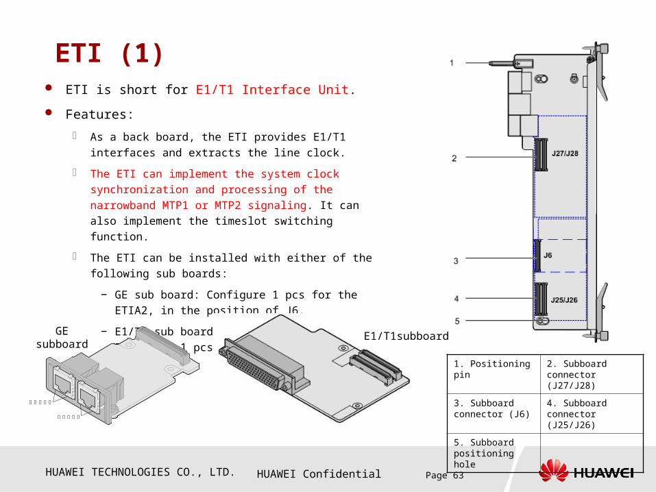
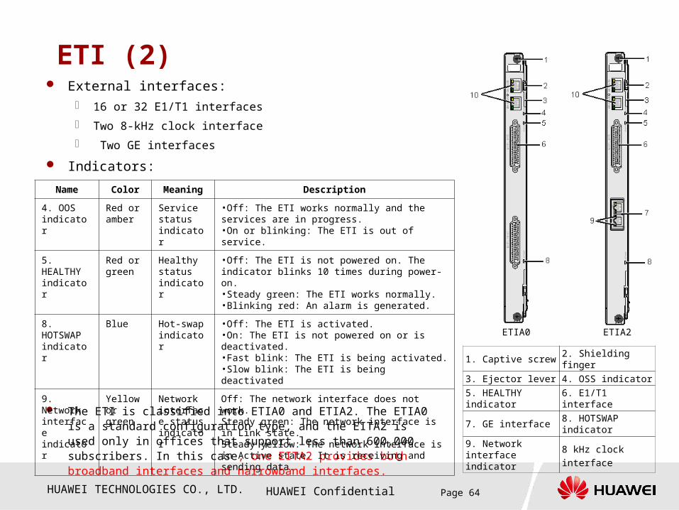
ETI (1) ETI is short for E1/T1 Interface Unit.
Features:
As a back board, the ETI provides E1/T1 interfaces and
extracts the line clock.
The ETI can implement the system clock synchronization and
processing of the narrowband MTP1 or MTP2 signaling. It
can also implement the timeslot switching function.
The ETI can be installed with either of the following sub
boards:
− GE sub board: Configure 1 pcs for the ETIA2, in the
position of J6.
− E1/T1 sub board: Configure 2 pcs for the ETIA0 and 1
pcs for the ETIA2.
1. Positioning pin 2. Subboard connector (J27/J28)
3. Subboard connector (J6)
4. Subboard connector (J25/J26)
5. Subboard positioning hole
网口指示灯
网口指示灯
GE subboard
E1/T1subboard
HUAWEI TECHNOLOGIES CO., LTD. HUAWEI Confidential Page 64
ETI (2)
Indicators:
1. Captive screw 2. Shielding finger
3. Ejector lever 4. OSS indicator
5. HEALTHY indicator
6. E1/T1 interface
7. GE interface8. HOTSWAP indicator
9. Network interface indicator 8 kHz clock interface
External interfaces: 16 or 32 E1/T1 interfaces
Two 8-kHz clock interface
Two GE interfaces
The ETI is classified into ETIA0 and ETIA2. The ETIA0 is a standard configuration type, and the EITA2 is used only in offices that support less than 600,000 subscribers. In this case, one EITA2 provides both broadband interfaces and narrowband interfaces.
ETIA0 ETIA2
Name Color Meaning Description
4. OOS indicator
Red or amber
Service status indicator
•Off: The ETI works normally and the services are in progress.•On or blinking: The ETI is out of service.
5. HEALTHY indicator
Red or green
Healthy status indicator
•Off: The ETI is not powered on. The indicator blinks 10 times during power-on.•Steady green: The ETI works normally.•Blinking red: An alarm is generated.
8. HOTSWAP indicator
Blue Hot-swap indicator
•Off: The ETI is activated.•On: The ETI is not powered on or is deactivated.•Fast blink: The ETI is being activated.•Slow blink: The ETI is being deactivated
9. Network interface indicator
Yellow or green
Network interface status indicator
Off: The network interface does not work.Steady green: The network interface is in Link state.Steady yellow: The network interface is in Active state. It is receiving and sending data.
HUAWEI TECHNOLOGIES CO., LTD. HUAWEI Confidential Page 65
Questions
How many subsystems is the MSOFTX3000 OSTA2.0 platform logically composed of?
Which board is used to set the subrack number in the MSOFTX3000 OSTA2.0 platform?
Which board is responsible for implementing subrack management in the MSOFTX3000 OSTA2.0 platform?
Which board is responsible for implementing subrack cascading in the MSOFTX3000 OSTA2.0 platform? How many cascading subracks are supported by the MSOFTX3000 hardware?
How many configuration types of does the UPB have in the MSOFTX3000 OSTA2.0 platform? What are their functions?
What kind of physical interfaces can be provided by the SUI in the MSOFTX3000 OSTA2.0 platform? How many types are these interfaces classified into?

HUAWEI TECHNOLOGIES CO., LTD. HUAWEI Confidential Page 66
AnswersHow many subsystems is the MSOFTX3000 OSTA2.0
platform logically composed of?
Logically, the MSOFTX3000 OSTA2.0 platform is composed of service
processing subsystem, switching subsystem, electromechanical
subsystem, and equipment management subsystem.
Which board is used to set the sub rack number in the
MSOFTX3000 OSTA2.0 platform?
The SDM is used to set the sub rack number in the MSOFTX3000
OSTA2.0 platform.
Which board is responsible for implementing sub rack
management in the MSOFTX3000 OSTA2.0 platform?
The SM M is responsible for implementing sub rack management in the
MSOFTX3000 OSTA2.0 platform.
HUAWEI TECHNOLOGIES CO., LTD. HUAWEI Confidential Page 67
Answers Which board is responsible for implementing subrack cascading
in the MSOFTX3000 OSTA2.0 platform? How many cascading
subracks are supported by the MSOFTX3000 hardware?
The SWU and SWI together are responsible for implementing subrack cascading in the
MSOFTX3000 OSTA2.0 platform. The MSOFTX3000 hardware supports a maximum of
nine subracks for cascading.
How many configuration types of does the UPB have in the
MSOFTX3000 OSTA2.0 platform? What are their functions?
In the MSOFTX3000 OSTA2.0 platform, the UPB is classified into UPBA0 and UPBA1.
The UPBA0 can serve as a service process board that is configured with specified
processes such as the CCU or BSG. The UPBA1 can server as a server board that is
configured with the OMU or iGWB.
What kind of physical interfaces can be provided by the SUI in
the MSOFTX3000 OSTA2.0 platform? How many types can these
interfaces be classified into?
In the MSOFTX3000 OSTA2.0 platform, the USI provides the 100/1000M auto-sensing
Ethernet interfaces, which can be classified into the OMC interface, NTP interface,
charging interface, interception interface, and broadband signaling interface.

HUAWEI TECHNOLOGIES CO., LTD. HUAWEI Confidential Page 68
Contents
Chapter 1 Overview
Chapter 2 Overall System
Chapter 3 Boards
Chapter 4 Signal Flow
Chapter 5 Cable Connection

HUAWEI TECHNOLOGIES CO., LTD. HUAWEI Confidential Page 69
Chapter 4 Signal Flow
Section 1 Signal Flow of the IPMB Bus
Section 2 Signal Flow of the Base Plane
Section 3 Signal Flow of the Fabric Plane
Section 4 Signal Flow of the TDM Clock
and Signaling
Section 5 Others

HUAWEI TECHNOLOGIES CO., LTD. HUAWEI Confidential Page 70
Signal Flow of the IPMB Bus - In a Subrack
UPB UPB
USI
IP Network
OMU OMU CSCF CSCF
USI
SMM SMM
GE/FE GE/FE
交换网板SWU
交换网板SWU
维护 Lanswitch 维护 Lanswitch
USI
IP Network
OMU OMU UPB UPB
USI
SMM SMM
GE/FE GE/FE
SWU SWU
LMT
IPMB management message flowSelf management module
Switching moduleUniversal processing module
Universal service interface
Fabric plane (service plane)
Management message flow
IPMB plane (device management plane)
Base pane (management plane)
TDM plane (narrowband service plane)
OM LAN Switch OM LAN Switch
HUAWEI TECHNOLOGIES CO., LTD. HUAWEI Confidential Page 71
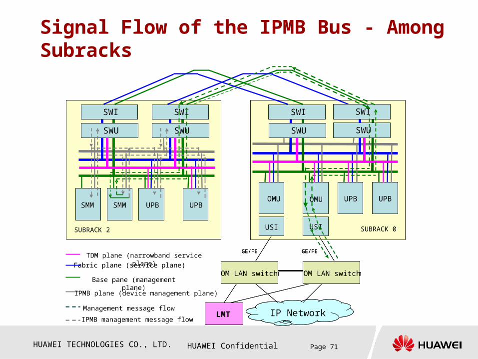
Signal Flow of the IPMB Bus - Among Subracks
UPB UPBUPB UPB
后插板USI
IP Network
OMU OMU
后插板USI
交换网板SWU
CSCF CSCF
交换网板SWU
交换网板SWU
2框 0
CSCF CSCFSMM SMM
维护 Lanswitch 维护 Lanswitch
GE/FEGE/FE
USI
IP Network
OMU OMU
USI
UPB UPB
SUBRACK 2 SUBRACK 0
UPB UPBSMM SMM
LMT
GE/FEGE/FE
SWUSWU
SWI
SWUSWU
SWI
SWUSWU
SWI
SWUSWU
SWI
IPMB management message flow
Fabric plane (service plane)
Management message flow
IPMB plane (device management plane)
Base pane (management plane)
TDM plane (narrowband service plane)
OM LAN switch OM LAN switch

HUAWEI TECHNOLOGIES CO., LTD. HUAWEI Confidential Page 72
Chapter 4 Signal Flow
Section 1 Signal Flow of the IPMB Bus
Section 2 Signal Flow of the Base Plane
Section 3 Signal Flow of the Fabric Plane
Section 4 Signal Flow of the TDM Clock
and Signaling
Section 5 Others
HUAWEI TECHNOLOGIES CO., LTD. HUAWEI Confidential Page 73
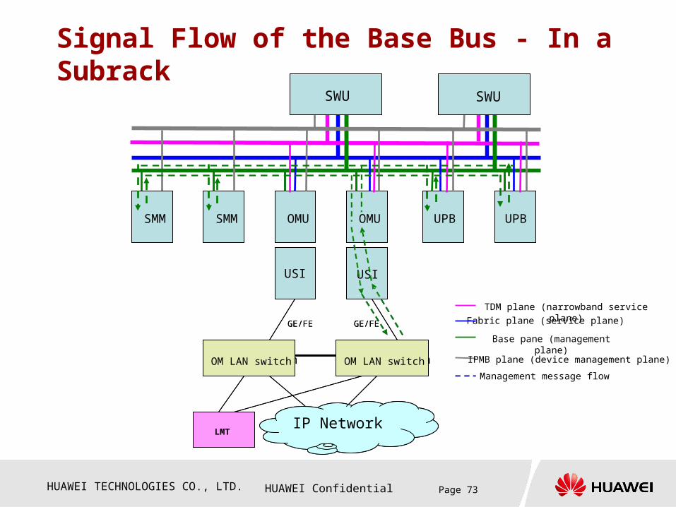
Signal Flow of the Base Bus - In a Subrack
UPB UPB
USI
IP Network
OMU OMU CSCF CSCF
USI
SMM SMM
GE/FE GE/FE
交换网板SWU
交换网板SWU
维护 Lanswitch 维护 Lanswitch
USI
IP Network
OMU OMU UPB UPB
USI
SMM SMM
GE/FE GE/FE
SWU SWU
LMT
TDM plane (narrowband service plane)
Fabric plane (service plane)
Management message flow
IPMB plane (device management plane)
Base pane (management plane)
OM LAN switch OM LAN switch
HUAWEI TECHNOLOGIES CO., LTD. HUAWEI Confidential Page 74
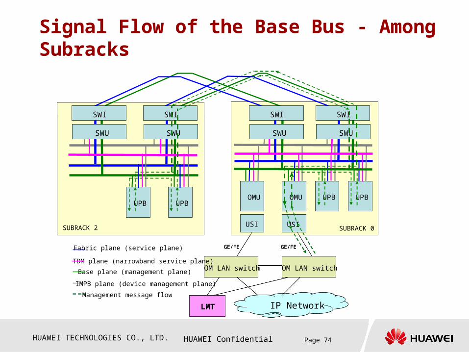
Signal Flow of the Base Bus - Among Subracks
UPBUPBUPBUPB
USI
IP Network
OMU OMU
后插板USI
CSCF CSCF
交换网板SWU
交换网板SWU
2框
CSCF CSCF
维护 Lanswitch 维护 Lanswitch
GE/FEGE/FE
USI
IP Network
OMU OMU
USI
UPB UPB
SUBRACK 2 SUBRACK 0
UPB UPB
LMT
OM LAN switch
GE/FEGE/FE
SWI
SWU
SWI
SWU
SWI
SWU
SWI
SWU
Fabric plane (service plane)
Management message flow
IMPB plane (device management plane)
Base plane (management plane)
TDM plane (narrowband service plane)OM LAN switch

HUAWEI TECHNOLOGIES CO., LTD. HUAWEI Confidential Page 75
Chapter 4 Signal Flow
Section 1 Signal Flow of the IPMB Bus
Section 2 Signal Flow of the Base Plane
Section 3 Signal Flow of the Fabric Plane
Section 4 Signal Flow of the TDM Clock and
Signaling
Section 5 Others
HUAWEI TECHNOLOGIES CO., LTD. HUAWEI Confidential Page 76
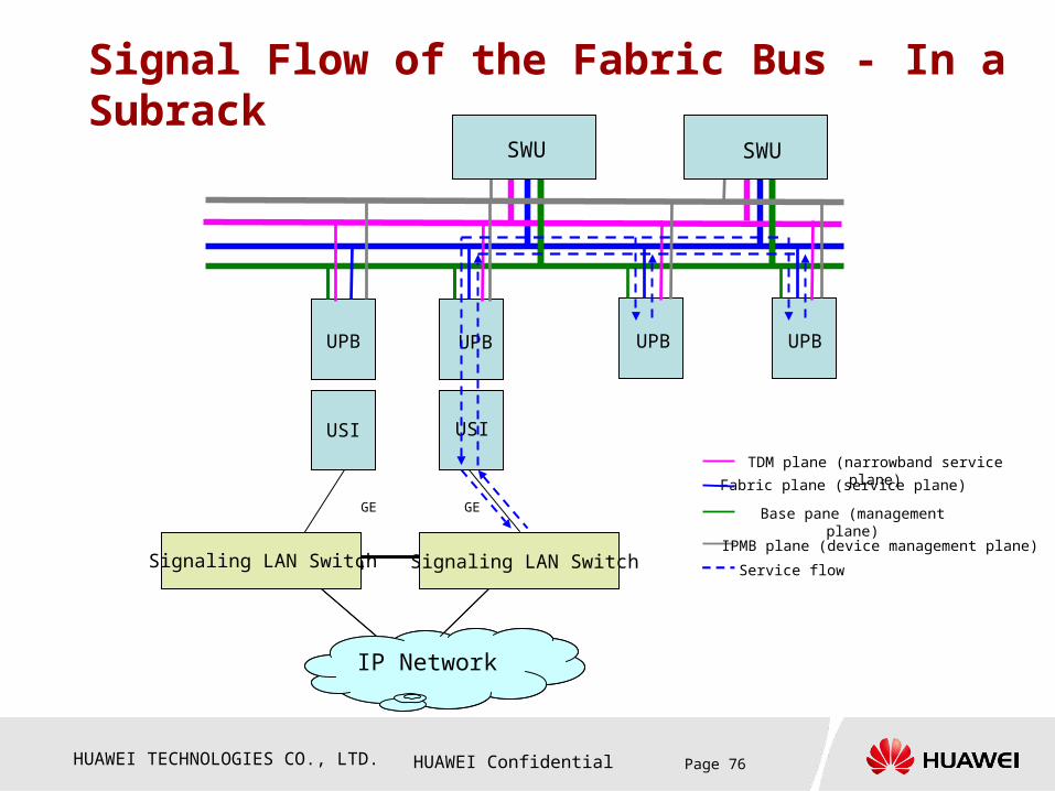
Signal Flow of the Fabric Bus - In a Subrack
UPB UPB
USI
IP Network
OMUOMU CSCF CSCF
交换网板SWU
交换网板SWU
维护 Lanswitch
USI
IP Network
OMUUPB UPB UPB
USI
GE GE
SWU SWU
Signaling LAN Switch Signaling LAN Switch
UPB
Service flow
TDM plane (narrowband service plane)
Fabric plane (service plane)
IPMB plane (device management plane)
Base pane (management plane)
HUAWEI TECHNOLOGIES CO., LTD. HUAWEI Confidential Page 77
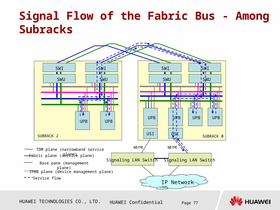
Signal Flow of the Fabric Bus - Among Subracks
UPBUPBUPBUPB
USI
IP Network
OMU OMU
后插板USI
CSCF CSCF
交换网板SWU
交换网板SWU
2框
CSCF CSCF
GE/FEGE/FE
USI
IP Network
UPB UPB
USI
UPB UPB
SUBRACK 2 SUBRACK 0
UPB UPB
Signaling LAN Switch
GE/FEGE/FE
SWI
SWU
SWI
SWU
SWI
SWU
SWI
SWU
Signaling LAN Switch
Service flow
TDM plane (narrowband service plane)
Fabric plane (service plane)
IPMB plane (device management plane)
Base pane (management plane)
HUAWEI TECHNOLOGIES CO., LTD. HUAWEI Confidential Page 78
Chapter 4 Signal Flow
Section 1 Signal Flow of the IPMB Bus
Section 2 Signal Flow of the Base Plane
Section 3 Signal Flow of the Fabric Plane
Section 4 Signal Flow of the TDM Clock
and Signaling
Section 5 Others

HUAWEI TECHNOLOGIES CO., LTD. HUAWEI Confidential Page 79
Signal Flow of the TDM Clock and Signaling – In a subrack
BITS0
UPB UPBOMUOMU CSCF CSCF
ETI
OMUUPB UPB UPB
SWU
UPB
ETI
SWI
SWU
SWI
BITS1
2Mbps/2MHz
ETI* ETI#
E1
E1
8kHz
Each SWIA provides one BITS interface and two 8-kHz line clock interfaces. After the SWIA receives a BITS clock source, the BITS clock source is divided into two sources in the SWIA. One of the sources is used for the current board and the other is used for the corresponding standby board. Therefore, from the view of the clock module, each SWIA can provide a maximum of two BITS lock sources and two 8-kHz line clock sources, that is, four clock sources.
Narrowband signaling flow
Narrowband clock flow
Service flow
TDM plane (narrowband service plane)
Fabric plane (service plane)
IPMB plane (device management plane)
Base pane (management plane)
HUAWEI TECHNOLOGIES CO., LTD. HUAWEI Confidential Page 80
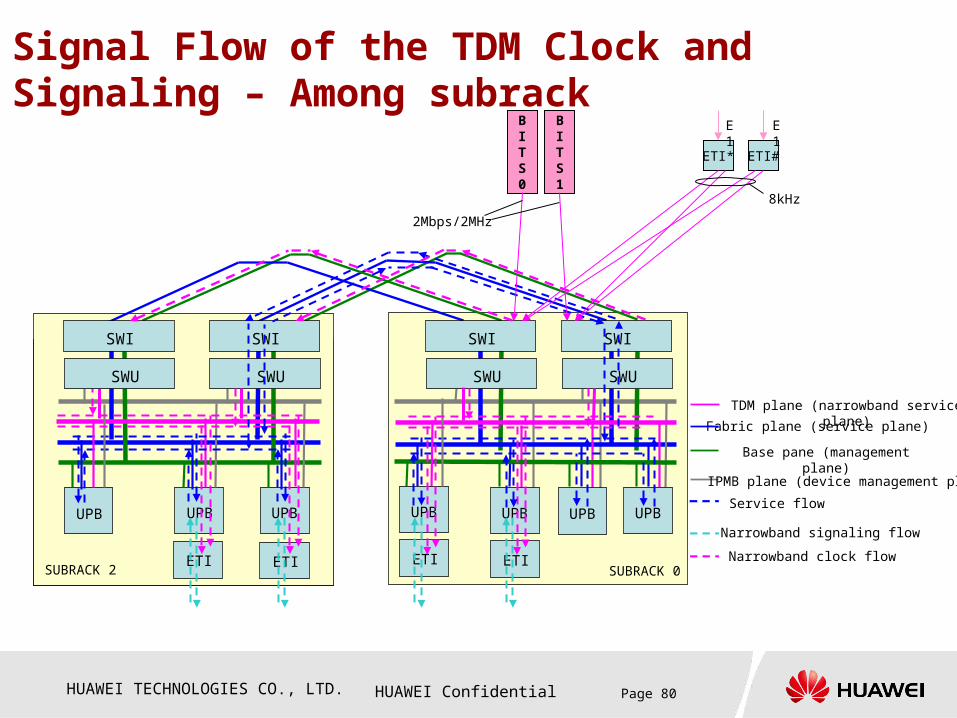
Signal Flow of the TDM Clock and Signaling – Among subrack
UPBOMU
CSCF
交换网板SWU
交换网板SWU
ETI
UPB UPB
SUBRACK 2 SUBRACK 0
SWI
SWU
SWI
SWU
SWI
SWU
ETI ETI
UPB
ETI
UPB UPB UPBUPB
BITS0
BITS1
2Mbps/2MHz
ETI* ETI#
E1
E1
8kHz
SWI
SWU
Narrowband signaling flow
Narrowband clock flow
Service flow
TDM plane (narrowband service plane)
Fabric plane (service plane)
IPMB plane (device management plane)
Base pane (management plane)

HUAWEI TECHNOLOGIES CO., LTD. HUAWEI Confidential Page 81
Chapter 4 Signal Flow
Section 1 Signal Flow of the IPMB Bus
Section 2 Signal Flow of the Base Plane
Section 3 Signal Flow of the Fabric Plane
Section 4 Signal Flow of the TDM Clock and
Signaling
Section 5 Others
HUAWEI TECHNOLOGIES CO., LTD. HUAWEI Confidential Page 82
Time Synchronization Signal Flow
UPBUPBUPBUPB
USI
OMU OMU
后插板USI
Time synchronization signal flow
CSCF CSCF
交换网板SWU
交换网板SWU
2框
CSCF CSCF
GE/FE
USI
IP NetworkIP Network
OMU OMU
USI
UPB UPB
SUBRACK 2 SUBRACK 0
UPB UPB
NTP server
GE/FE
SWI
SWU
SWI
SWU
SWI
SWU
SWI
SWU
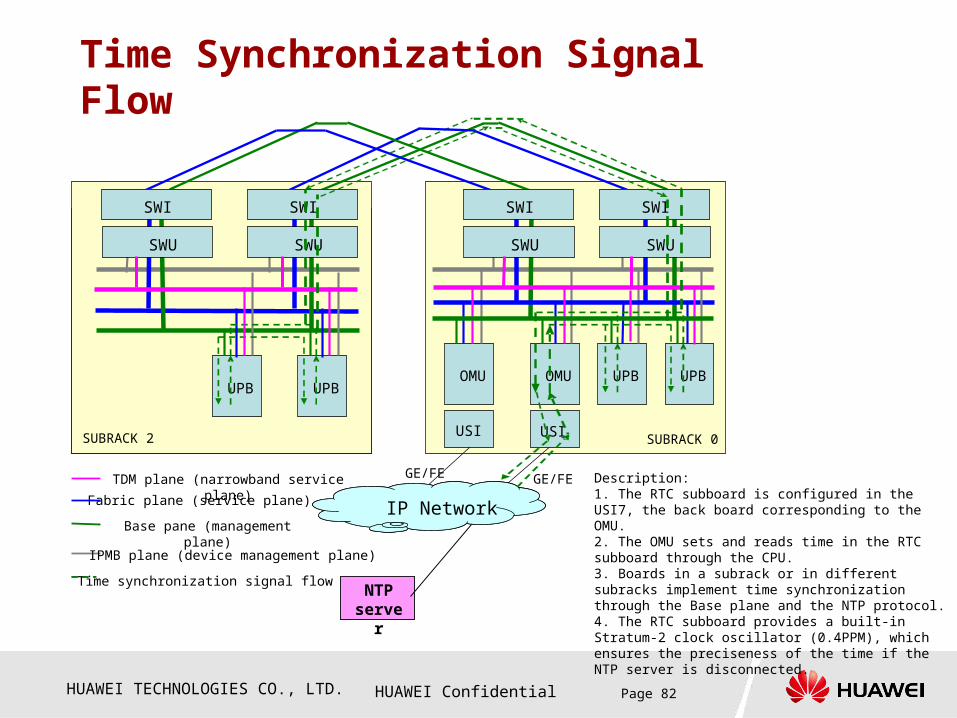
Description:1. The RTC subboard is configured in the USI7, the back board corresponding to the OMU.2. The OMU sets and reads time in the RTC subboard through the CPU.3. Boards in a subrack or in different subracks implement time synchronization through the Base plane and the NTP protocol.4. The RTC subboard provides a built-in Stratum-2 clock oscillator (0.4PPM), which ensures the preciseness of the time if the NTP server is disconnected.
TDM plane (narrowband service plane)
Fabric plane (service plane)
IPMB plane (device management plane)
Base pane (management plane)
HUAWEI TECHNOLOGIES CO., LTD. HUAWEI Confidential Page 83
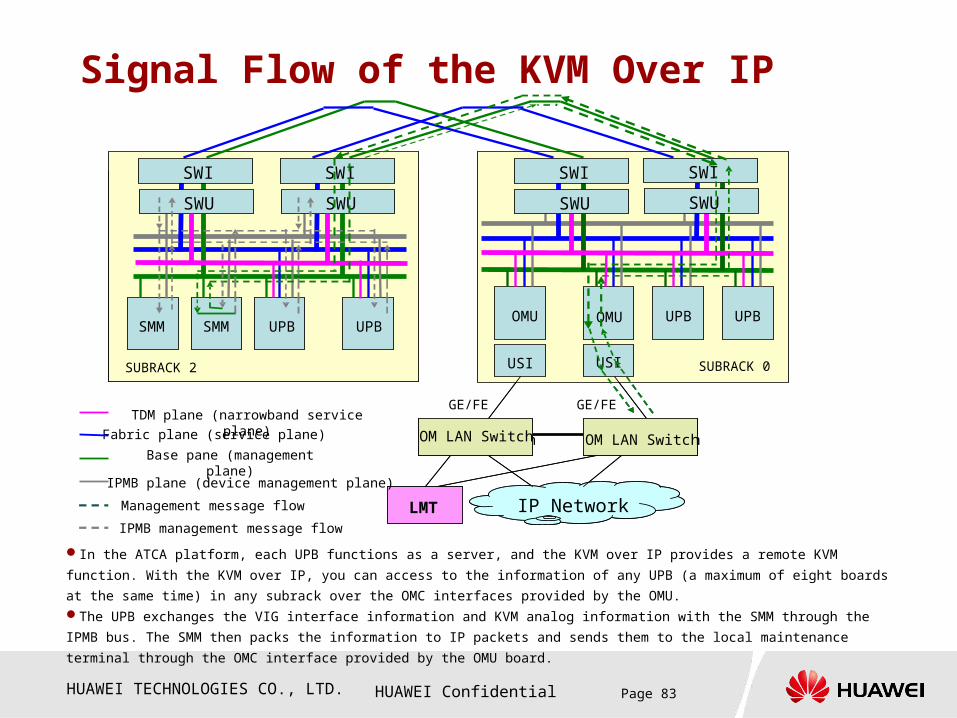
Signal Flow of the KVM Over IP
In the ATCA platform, each UPB functions as a server, and the KVM over IP provides a remote KVM function. With the KVM over IP, you
can access to the information of any UPB (a maximum of eight boards at the same time) in any subrack over the OMC interfaces provided by
the OMU.The UPB exchanges the VIG interface information and KVM analog information with the SMM through the IPMB bus. The SMM then packs
the information to IP packets and sends them to the local maintenance terminal through the OMC interface provided by the OMU board.
UPB UPBUPB UPB
后插板USI
IP Network
OMU OMU
后插板USI
交换网板SWU
CSCF CSCF
交换网板SWU
交换网板SWU
2框 0
CSCF CSCFSMM SMM
维护 Lanswitch 维护 Lanswitch
GE/FEGE/FE
USI
IP Network
OMU OMU
USI
UPB UPB
SUBRACK 2 SUBRACK 0
UPB UPBSMM SMM
LMT
OM LAN Switch
SWUSWU
SWI
SWUSWU
SWI
SWUSWU
SWI
SWUSWU
SWI
OM LAN Switch
IPMB management message flow
Fabric plane (service plane)
Management message flow
IPMB plane (device management plane)
Base pane (management plane)
TDM plane (narrowband service plane)

HUAWEI TECHNOLOGIES CO., LTD. HUAWEI Confidential Page 84
Questions
How many types of signal flow are provided by the MSOFTX3000 OSTA2.0 platform?
If the hardware of a board is faulty in the MSOFTX3000 OSTA2.0 platform, how is an alarm generated for this failure?
In the MSOFTX3000 OSTA2.0 platform, how is the clock distribution among the narrowband clock subracks implemented? How is the narrowband signal flow implemented?
In the MSOFTX3000 OSTA2.0 platform, how is the time synchronization implemented?
In the MSOFTX3000 OSTA2.0 platform, which boards does the signal flow of KVM over IP pass through?

HUAWEI TECHNOLOGIES CO., LTD. HUAWEI Confidential Page 85
Answers How many types of signal flow are provided by the MSOFTX3000 OSTA2.0 platform?There are four types of signal flow: IPMB bus signal flow, Base plane signal flow, Fabric plane signal flow, and TDM bus signal flow.
If the hardware of a board is faulty in the MSOFTX3000 OSTA2.0 platform, how is an alarm generated for this failure?The faulty board generates an alarm and reports the alarm to the SMM in the subrack through the IPMB bus. The SMM then reports the alarm to the OMU through the Base plane.
In the MSOFTX3000 OSTA2.0 platform, how is the clock distribution among the narrowband clock subracks implemented? How is the narrowband signal flow implemented? The SWI in subrack 0 generates the internal reference clock after locking the external reference clock, and then delivers the internal reference clock to the SWU in subrack 0. The SWU then delivers the reference clock to each ETI in the current subrack through the TDM bus. For the clock distribution among subracks, the SWU in subrack 0 delivers the internal reference clock to the SWI in each expansion subrack through the Base cascading interfaces. The SWI then retracts the reference clock and delivers it to the corresponding SWU, and the SWU is responsible for delivers the reference clock to each ETI.
After being exported through the E1 interface of the ETI, the narrowband signaling is processed for MTP1 and partial MTP2, and then delivered to the corresponding UPBs for other processing.

HUAWEI TECHNOLOGIES CO., LTD. HUAWEI Confidential Page 86
AnswersIn the MSOFTX3000 OSTA2.0 platform, how is the time
synchronization implemented?
The time synchronization is implemented through the Base bus. The OMU board
synchronizes time with NTP server through the NPT interface provided by its
corresponding back board and stores the time in the RTC sub board in the back
board. The time provided by the TRC sub board is considered as the system
time of the MSOFTX3000. All the modules in the system synchronize time
through the Base bus and NTP protocol.
In the MSOFTX3000 OSTA2.0 platform, which boards does
the signal flow of KVM over IP pass through?
The signal flow of the KVM Over IP passes through the UPBs, SMMs, SWUs,
and OMU board.

HUAWEI TECHNOLOGIES CO., LTD. HUAWEI Confidential Page 87
Contents
Chapter 1 Overview
Chapter 2 Overall System
Chapter 3 Boards
Chapter 4 Signal Flow
Chapter 5 Cable Connection
HUAWEI TECHNOLOGIES CO., LTD. HUAWEI Confidential Page 88
Chapter 5 Cascading and Cabling
Section 1 PDB Monitoring Cable
Section 2 Cascading Cable Among Subracks
Section 3 External Cable of the OMU/iGWB
Section 4 Broadband Service Cable
Section 5 Narrowband Service Cable

HUAWEI TECHNOLOGIES CO., LTD. HUAWEI Confidential Page 89
Installation of PDB Cables
The PDB working status is monitored by
the SMMs in the subrack located at the
bottom of a cabinet. For example, in an
integrated configuration cabinet, the PDB is
monitored by the SMMs in subrack 0, and
in a service processing cabinet, the PDB is
monitored by the SMMs in subrack 2.
During installation, one end of the PDB
cable is connected to the serial port
connectors in the monitoring panel at the
rear of the PDB and the other end is
connected to the COM2 serial ports in the
SDMs. Self data madule
The PDB cables are configured before
delivery; therefore, you need not configure
them on site.
PDB
OSTA2.0 RACK
OSTA2.0 RACK
OSTA2.0 RACK

HUAWEI TECHNOLOGIES CO., LTD. HUAWEI Confidential Page 90
Installation of Power Cables from the PDB to Internal Components of a Cabinet
Power cables have been bundled to cabinets before
delivery. If a cabinet is configured with subracks, LAN
Switches, and MTMU before delivery, the power cables
among these components have also been configured.
During capacity expansion, the power cables must be
reconnected on site. Master rack monitoring unit
Cabinet Switches Component
Integrated configuration cabinet
(A7 and A8) / (B7 and B8) SUBRACK-1 (expansion subrack 1)
A2/B2 MRMU
A3 LANS-1
B3 LANS-0
A1 KVMS
(A9 and A10) / ( B9 and B10 )
SUBRACK-0 (basic subrack 0)
Service
processin
g cabinet
(A7 and A8 ) / ( B7 and B8)
SUBRACK-1 (expansion subrack 3)
(A9 and A10) / ( B9 and B10 )
SUBRACK-0 (expansion subrack 2)
HUAWEI TECHNOLOGIES CO., LTD. HUAWEI Confidential Page 91
Chapter 5 Cascading and Cabling
Section 1 PDB Monitoring Cable
Section 2 Cascading Cable Among
Subracks
Section 3 External Cable of the OMU/iGWB
Section 4 Broadband Service Cable
Section 5 Narrowband Service Cable

HUAWEI TECHNOLOGIES CO., LTD. HUAWEI Confidential Page 92
Subrack Cascading Subrack cascading is implemented
through the GE interfaces provided by the
SWIs. The SWIs in expansion subracks
are connected to the SWIs in the basic
subrack through cables. One cable is
required for the Base bus and Fabric bus.
Principle for using ports: from the top to
the bottom and the topmost port first
Only LAN0 is available in an expansion
subrack. (The narrowband clock is
extracted through LAN0 of the Base
plane.)
0#
SWI
01234567
01234567
SWI
01234567
01234567
1#
SWI
01234567
01234567
SWI
01234567
01234567
2#
SWI
01234567
01234567
SWI
01234567
01234567
Base/TDM cascading interface
Fabric cascading interface

HUAWEI TECHNOLOGIES CO., LTD. HUAWEI Confidential Page 93
Subracks are connected using straight-through cables. Each subrack should be configured with four cables.
The interfaced provided by the SWI should be used from top to bottom. The LAN0 of an expansion subrack is permanently used for connection.
Base cascading interface
Fabric cascading interface
Subrack Cascading Diagram

HUAWEI TECHNOLOGIES CO., LTD. HUAWEI Confidential Page 94
Chapter 5 Cascading and Cabling
Section 1 PDB Monitoring Cables
Section 2 Cascading Cable Among
Subracks
Section 3 External Cables of the
OMU/iGWB
Section 4 Broadband Service Cables
Section 5 Narrowband Service Cables

HUAWEI TECHNOLOGIES CO., LTD. HUAWEI Confidential Page 95
Cable Configuration of the Back Board Corresponding to the OMU Board
OMC interface
NTP interface
Interception interface
The OMU board is generally configured in front slots 4 and 5 of subrack 0. Its corresponding back board is the USIA7, which provides six 100M/1000M autonegotiation Ethernet interfaces.
The USIA7 provides three logical interfaces, namely, OMC interface, NTP interface, and interception interface. For details, see the figure above.
Note that the physical cable connection must be consistent with the data configuration.

HUAWEI TECHNOLOGIES CO., LTD. HUAWEI Confidential Page 96
Cable Configuration of the Back Board Corresponding to the iGWB Board
Charging interface
The iGWB board is generally configured in front slots 4 and 5 and slot 8 and 9 of a subrack. Its corresponding back board is the USIA1, which provides four 100M/1000M autonegotiation Ethernet interfaces.
The iGWB board supports only one charging interface, which is the first interface (from the top to the bottom) of the USIA1, that is, Card3 LAN0. For details, see the figure above.
Note that the physical cable connection must be consistent with the data configuration.
HUAWEI TECHNOLOGIES CO., LTD. HUAWEI Confidential Page 97
Chapter 5 Cascading and Cabling
Section 1 PDB Monitoring Cable
Section 2 Cascading Cable Among
Subracks
Section 3 External Cable of the
OMU/iGWB
Section 4 Broadband Service Cable
Section 5 Narrowband Service Cable

HUAWEI TECHNOLOGIES CO., LTD. HUAWEI Confidential Page 98
Broadband Signaling Cable Configuration
Broadband interface
The back board corresponding to the UPB that is configured with an IFM process is the USIA1. Such UPBs are generated configured in slots 0 and 1 of a subrack. The USIA1 provides four 100M/1000M autonegotiation Ethernet interfaces.
The broadband interface refers to the first interface (from the top to the bottom) of the USIA1, that is, Card3 LAN0. For details, see the figure above.
Note that the physical cable connection must be consistent with the data configuration.
To the IP Backbone network
HUAWEI TECHNOLOGIES CO., LTD. HUAWEI Confidential Page 99
Broadband Signaling Cable Configuration
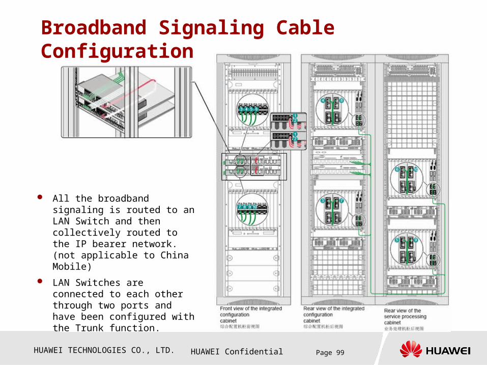
All the broadband signaling is routed to an LAN Switch and then collectively routed to the IP bearer network. (not applicable to China Mobile)
LAN Switches are connected to each other through two ports and have been configured with the Trunk function.
HUAWEI TECHNOLOGIES CO., LTD. HUAWEI Confidential Page 100
Chapter 5 Cascading and Cabling
Section 1 PDB Monitoring Cable
Section 2 Cascading Cable Among
Subracks
Section 3 External Cable of the
OMU/iGWB
Section 4 Broadband Service Cable
Section 5 Narrowband Service Cable

HUAWEI TECHNOLOGIES CO., LTD. HUAWEI Confidential Page 101
Narrowband Clock Cable Configuration
The SWIA1 provides narrowband clock interfaces, namely, 2-Mbps/2-MHz BITS clock for external synchronization and 8-k clock interface. The SWIA1 can be installed only in back slots 6 and 7 of subrack 0.
The 8k clock is retrieved by the ETIA from the E1 links and then exported to the SWIA1. Note that the 8-kHz clocks of the same SWIA1 must be provided by two different ETIAs.
The BITS clock is provided by the external BITS device. The ATCA platform supports two independent BITS clock sources.
8 kHz clock interface
BITS clock interface
BITS0
BITS1

HUAWEI TECHNOLOGIES CO., LTD. HUAWEI Confidential Page 102
Trunk Cabling Configuration
Trunk cable connectors
The EITA0 or EITA2 provides narrowband signaling interfaces for the system. Each interface supports 16 E1 lines.
The trunk cables is classified into 75-ohm trunk cables and 120-ohm trunk cables.
During cable layout, all the trunk cables are led from the ETIs to a 2-U cabling though, and then laid along the both sides of a cabinet.

HUAWEI TECHNOLOGIES CO., LTD. HUAWEI Confidential Page 103
Questions
How to configure the cascading cables in the
MSOFTX3000 OSTA2.0 platform?
Which logical interfaces are provided by the back board
corresponding to the OMU board? How are the cables
connected?
Which board provides the narrowband clock interface?
How many types of clock interfaces are provided? How
are the cables connected?
Where are the broadband signaling interfaces
configured in a subrack? How the cables are
connected?
HUAWEI TECHNOLOGIES CO., LTD. HUAWEI Confidential Page 104
Answers
How to configure the cascading cables in the MSOFTX3000
OSTA2.0 platform?
Each OSTA2.0 subrack requires four straight through cables for cascading, with two
cables for each SWI, one for the Base plane, and one for the Fabric plane. The SWI
provides eight interfaces for the Base plane and eight interfaces for the Fabric plane.
All the interfaces provided by the SWI in subrack 0 can be used in the sequence from 0
to 7. For the other subracks, only interface LAN0 is available among the interfaces
provided by SWI. (For details, see P90.)
Which logical interfaces are provided by the back board
corresponding to the OMU board? How are the cables
connected?
The back board corresponding to the OMU board provides three types of interfaces:
OMC interface, NTP interface, and interception interface. The physical port numbers
corresponding to these three interfaces are Card2/Lan0, Card2/Lan1, and Card4/Lan0.
For details about the cable connection, see P93.
HUAWEI TECHNOLOGIES CO., LTD. HUAWEI Confidential Page 105
Answers
Which board provides the narrowband clock interface?
How many types of clock interfaces are provided? How
are the cables connected?
The SWI (to be specific, SWIA1) provides the narrowband clock interfaces,
support the external BITS clock source and 8-kHz line clock source. For
details about the cable connection, see P99.
Where are the broadband signaling interfaces
configured in a subrack? How the cables are connected?
The narrowband signaling interface is generally configured in slots 0 and
1. The corresponding front board is configured with the IFM process. For
details about the cable connection, see P95.

Thank Youwww.huawei.com