ata interface drive - seagate.com this manual by its model number, st5850a. the st5850a is a...
TRANSCRIPT

. . . . . . . . . . . . . . . . . . . . . . . . . . . . . . . . . . . . .. . . . .
Decathlon 850 . . . . . . . . . . . . . . . . . . . . . . . . . . . . . . . . . . . . .. . . . .
ATA Interface Drive. . . . . . . . . . . . . . . . . . . . . . . . . . . . . . . . . . . . .
. . . . . . . . . . . . . . . . . . . . . . . . . . . . . . . . . . . . .. . . . .
. . . . . . . . . . . . . . . . . . . . . . . . . . . . . . . . . . . . .. . . . .
Product Manual. . . . . . . . . . . . . . . . . . . . . . . . . . . . . . . . . . . . .. . . . .

. . . . . . . . . . . . . . . . . . . . . . . . . . . . . . . . . . . . .. .
Decathlon 850. . . . . . . . . . . . . . . . . . . . . . . . . . . . . . . . . . . . .. . . . .
ATA Interface Drive. . . . . . . . . . . . . . . . . . . . . . . . . . . . . . . . . . . . .. . . . . . . .
. . . . . . . . . . . . . . . . . . . . . . . . . . . . . . . . . . . . .. .
. . . . . . . . . . . . . . . . . . . . . . . . . . . . . . . . . . . . .. . . . .
Product Manual. . . . . . . . . . . . . . . . . . . . . . . . . . . . . . . . . . . . .. . . . .

© 1995 Seagate Technology, Inc. All rights reserved
Publication Number: 36326-001, Rev. A, July 1995Supersedes Publication Number 36279-xxx
Seagate, Seagate Technology and the Seagate logo are registeredtrademarks of Seagate Technology, Inc. Decathlon is a trademark ofSeagate Technology, Inc. Other product names are trademarks or reg-istered trademarks of their owners.
Seagate reserves the right to change, without notice, product offeringsor specifications. No part of this publication may be reproduced in anyform without written permission from Seagate Technology, Inc.

Contents
Introduction . . . . . . . . . . . . . . . . . . . . . . . . . . . . . 1
1.0 Specifications . . . . . . . . . . . . . . . . . . . . . . . . . . 3
1.1 Formatted capacity . . . . . . . . . . . . . . . . . . . . . . . 3
1.1.1 Standard configuration . . . . . . . . . . . . . . . . . . 3
1.2 528-Mbyte capacity barrier . . . . . . . . . . . . . . . . . . . 3
1.3 Physical organization . . . . . . . . . . . . . . . . . . . . . . 4
1.4 Functional specifications . . . . . . . . . . . . . . . . . . . . 5
1.5 Physical dimensions . . . . . . . . . . . . . . . . . . . . . . 5
1.6 Seek time . . . . . . . . . . . . . . . . . . . . . . . . . . . . 6
1.7 Start and stop times . . . . . . . . . . . . . . . . . . . . . . 6
1.8 Typical power-up and power-down sequence . . . . . . . . . 6
1.8.1 Power-up sequence . . . . . . . . . . . . . . . . . . . . 7
1.8.2 Power-down sequence . . . . . . . . . . . . . . . . . . 7
1.8.3 Auto-park . . . . . . . . . . . . . . . . . . . . . . . . . 8
1.9 Power specifications . . . . . . . . . . . . . . . . . . . . . . 8
1.9.1 Power consumption . . . . . . . . . . . . . . . . . . . . 8
1.9.2 Voltage tolerance . . . . . . . . . . . . . . . . . . . . . 9
1.9.3 Input noise . . . . . . . . . . . . . . . . . . . . . . . . 9
1.10 Environmental specifications . . . . . . . . . . . . . . . . 10
1.10.1 Ambient temperature . . . . . . . . . . . . . . . . . 10
1.10.2 Temperature gradient . . . . . . . . . . . . . . . . . 10
1.10.3 Altitude . . . . . . . . . . . . . . . . . . . . . . . . . 10
1.10.4 Relative humidity . . . . . . . . . . . . . . . . . . . 10
1.10.5 Shock and vibration . . . . . . . . . . . . . . . . . . 10
1.11 Acoustics . . . . . . . . . . . . . . . . . . . . . . . . . . 11
1.12 Reliability . . . . . . . . . . . . . . . . . . . . . . . . . . 11
1.13 Agency listings . . . . . . . . . . . . . . . . . . . . . . . 12
1.14 FCC verification . . . . . . . . . . . . . . . . . . . . . . . 12
2.0 Configuring and mounting the drive . . . . . . . . . . . . . 15
2.1 Handling and static-discharge precautions . . . . . . . . . . 15
Decathlon 850 ATA Product Manual, July 1995 iii
2.2 I/O connector . . . . . . . . . . . . . . . . . . . . . . . . 16
2.3 Power connector . . . . . . . . . . . . . . . . . . . . . . . 16
2.4 Options jumper block (J8) . . . . . . . . . . . . . . . . . . 17
2.4.1 Spare jumpers . . . . . . . . . . . . . . . . . . . . . 17
2.4.2 Master/slave configuration . . . . . . . . . . . . . . . 17
2.4.3 Master/slave timing protocol . . . . . . . . . . . . . . 17
2.4.4 Dual-drive emulation . . . . . . . . . . . . . . . . . . 22
2.4.5 Remote LED connection . . . . . . . . . . . . . . . . 22
2.4.6 Cable-select option . . . . . . . . . . . . . . . . . . . 22
2.5 Mounting the drive . . . . . . . . . . . . . . . . . . . . . . 23
3.0 ATA interface . . . . . . . . . . . . . . . . . . . . . . . . . . 25
3.1 ATA interface connector pin assignments . . . . . . . . . . 25
3.2 Command set . . . . . . . . . . . . . . . . . . . . . . . . 27
3.2.1 Identify Drive command (ECH) . . . . . . . . . . . . . 29
3.2.2 Set Features command (EFH) . . . . . . . . . . . . . 31
3.2.3 Sleep command (99H, E6H) . . . . . . . . . . . . . . . 33
Appendix. Timing diagrams . . . . . . . . . . . . . . . . . . . . 35
iv Decathlon 850 ATA Product Manual, July 1995

Figures
Figure 1. Typical startup current profile . . . . . . . . . . . . . . 7
Figure 2. ATA interface connector . . . . . . . . . . . . . . . . 16
Figure 3. Type A connectors . . . . . . . . . . . . . . . . . . . 18
Figure 4. Type A configuration settings . . . . . . . . . . . . . 19
Figure 5. Type B connectors . . . . . . . . . . . . . . . . . . . 20
Figure 6. Type B configuration settings . . . . . . . . . . . . . 21
Figure 7. Connecting cable-selected devices . . . . . . . . . . 23
Figure 8. Mounting dimensions . . . . . . . . . . . . . . . . . . 24
Figure 9. ATA interface connector pin assignments . . . . . . 26
Figure 10. Programmed I/O timing without IORDY . . . . . . . 35
Figure 11. Programmed I/O timing with IORDY . . . . . . . . . 36
Figure 12. Multiword DMA timing . . . . . . . . . . . . . . . . . 37
Decathlon 850 ATA Product Manual, July 1995 v


IntroductionThis manual describes the functional, mechanical and interface specifi-cations for the Decathlon 850 hard disc drive. The drive is referred tothroughout this manual by its model number, ST5850A.
The ST5850A is a high-capacity, high-performance, energy-efficientdrive that comes in the mini 3.5-inch form-factor. It is capable of meetingthe needs of PCI, VL, ISA and EISA bus computers.
The drive features Fast ATA-2 performance. It supports PIO mode 4 andmultiword DMA mode 2 transfer modes and multiple block read/write.When the host chooses either of these modes, the drive is capable ofburst transfer rates of up to 16.6 Mbytes per second. Multiple blockread/write allows the drive to gather several blocks of data in cache andtransfers them in a single burst.
The interface is supported with a 256-Kbyte segmented cache andembedded servo technology. The segmented cache aids the flow of readand write data. The embedded servo allows for accurate positioning ofthe heads over the data and eliminates periodic thermal recalibration toassure data transfer without interruption.
Energy-saving features are designed into the ST5850A drive. The drivecomplies with the ATA interface specifications for Active, Idle andStandby power modes. Power-saving modes are entered upon requestby the computer. Standby mode reduces the drive’s power consumptionto a typical 1 watt while retaining drive accessibility. (A complete listingof the ATA commands the drive supports is found on pages 27 and 28.ATA commands and features with specific applications for the drive arediscussed in Section 3.0 on page 25.)
Decathlon drives conform to the standard 3.5-inch footprint but have a0.75-inch (19-mm) high profile. The lower height gives the designer orintegrator more room for air circulation, other peripherals or a smallerdrive bay.
The following is a summary of the drive’s features:
Capacity
• 854 Mbytes formatted
• LBA translation support
• Dual-drive emulation, which turns the drive into two logical drives forDOS computers that limit the drive’s capacity to 528 Mbytes
• Available installation software to surpass the 528-Mbyte barrier im-posed by some BIOSs
Decathlon 850 ATA Product Manual, July 1995 1

• Available software driver that provides expanded 32-bit disk accesssupport for Windows
Performance
• Multiword DMA modes 0, 1 and 2 and PIO modes 0,1, 2, 3 and 4
• Multiple block read/write
• 5,400-RPM rotational speed
• 256-Kbyte segmented buffer
• 12-msec average seek time
Energy efficiency
• Implements an ATA-compliant power-management system using Ac-tive, Idle and Standby modes
• 1 watt typical power dissipation rating in Standby mode
Acoustics
• 30-dBA typical idle acoustic sound pressure level
Mini 3.5-inch form-factor
• 19-mm-high profile
• Fits standard 3.5-inch footprint
2 Decathlon 850 ATA Product Manual, July 1995
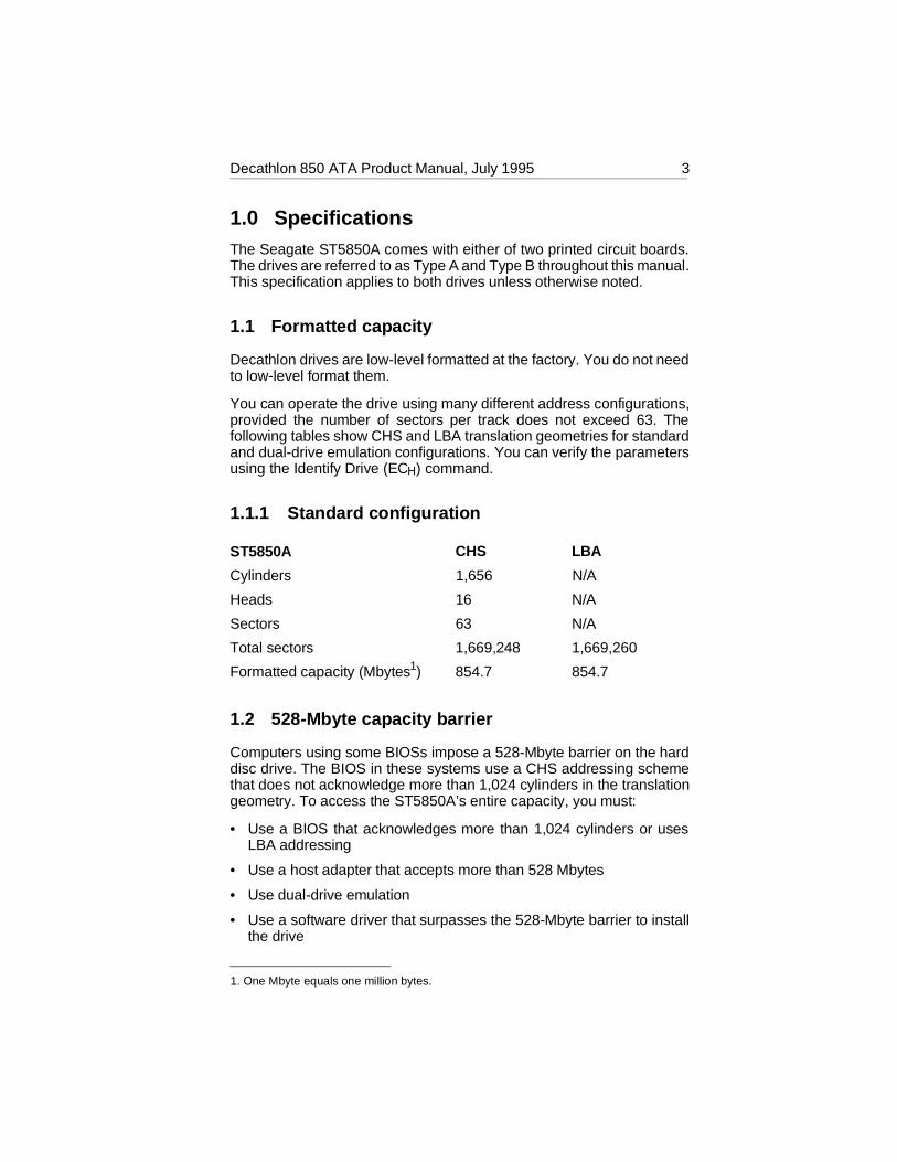
1.0 SpecificationsThe Seagate ST5850A comes with either of two printed circuit boards.The drives are referred to as Type A and Type B throughout this manual.This specification applies to both drives unless otherwise noted.
1.1 Formatted capacity
Decathlon drives are low-level formatted at the factory. You do not needto low-level format them.
You can operate the drive using many different address configurations,provided the number of sectors per track does not exceed 63. Thefollowing tables show CHS and LBA translation geometries for standardand dual-drive emulation configurations. You can verify the parametersusing the Identify Drive (ECH) command.
1.1.1 Standard configuration
ST5850A CHS LBA
Cylinders 1,656 N/A
Heads 16 N/A
Sectors 63 N/A
Total sectors 1,669,248 1,669,260
Formatted capacity (Mbytes1) 854.7 854.7
1.2 528-Mbyte capacity barrier
Computers using some BIOSs impose a 528-Mbyte barrier on the harddisc drive. The BIOS in these systems use a CHS addressing schemethat does not acknowledge more than 1,024 cylinders in the translationgeometry. To access the ST5850A’s entire capacity, you must:
• Use a BIOS that acknowledges more than 1,024 cylinders or usesLBA addressing
• Use a host adapter that accepts more than 528 Mbytes
• Use dual-drive emulation
• Use a software driver that surpasses the 528-Mbyte barrier to installthe drive
1. One Mbyte equals one million bytes.
Decathlon 850 ATA Product Manual, July 1995 3

1.2.0.1 Dual-drive emulation configuration
Dual-drive emulation is a jumper setting on the options jumper block—see Figure 3 on page 18 for Type A drives or Figure 4 on page 20 forType B drives—that allows you to configure the drive as two logicaldrives. Each logical drive is assigned a drive type in CMOS and ispartitioned and formatted. When dual-drive emulation is used, a secondphysical drive cannot be used on the controller.
ST5850A CHS LBA
Cylinders 827 N/A
Heads 16 N/A
Sectors 63 N/A
Total sectors 833,616 834,374
Formatted capacity (Mbytes) 426.8 427.2
1.2.0.2 Available software driver
The ST5850A is available with a software driver to surpass the 528-Mbyte barrier. Ask your Seagate representative for more information.
1.3 Physical organization
ST5850A
Read/write heads 4
Discs 2
4 Decathlon 850 ATA Product Manual, July 1995

1.4 Functional specifications
ST5850A
Interface ATA
Zone Bit Recording method RLL (1,7)
External data burst transfer rate:
DMA mode 2 (Mbytes per sec) 16.62
PIO mode 4 (Mbytes per sec) 16.63
Internal data-transfer rate(Mbits per sec) 32.45 to 61.65
Spindle speed (RPM) 5,376 ± 0.5%
Cache size (Kbytes) 256
Physical cylinders 4,085
Bytes per sector 512
Recording density, max (BPI) 69,355
Track density (TPI) 4,250
1.5 Physical dimensions
The mounting dimensions are shown in Figure 8 on page 24.
Height (max) 0.748 inches (19.0 mm)
Width (max) 4.00 inches (101.6 mm)
Depth (max) 5.00 inches (127.0 mm)
Weight 1.0 lb (0.45 Kg)
2. See Figure 12 on page 37 for timing specifications.
3. See Figure 11 on page 36 for timing specifications.
Decathlon 850 ATA Product Manual, July 1995 5

1.6 Seek time
Seek time is the interval between the time the actuator begins to moveand the time the head has settled over the target track. Seek time is astatistical average of at least 10,000 measurements of seek time. Allmeasurements for maximum values are taken under nominal conditionsof temperature and voltage with the drive mounted horizontally. Thespecifications in the table below are defined as follows:
• Track-to-track seek time is the average of all possible single-trackseeks in both directions.
• Average seek time is measured by executing seeks in both directionsbetween random cylinders.
• Full-stroke seek time is half the time needed to seek from track 0 tothe maximum track and back to track 0.
Track-to-trackseek time
Average/typicalseek time
Full-strokeseek time
Averagelatency
3.5 msec typ4.5 msec max
12 msec read14 msec write
25 msec typ27 msec max
5.56 msec
Note. Host overhead varies between systems and cannot be specified.Drive internal overhead is measured by issuing a no-motion seek.Overhead is typically less than 0.5 msec.
1.7 Start and stop times
The drive is ready within 20 seconds after the power is applied. The drivespindle stops rotating within 15 seconds after the power is removed.
1.8 Typical power-up and power-down sequence
A typical power-up and power-down sequence is described below toassist you in evaluating the drive’s performance. It is not a performancespecification. Each drive has a unique startup current profile similar toFigure 1.
6 Decathlon 850 ATA Product Manual, July 1995

1.8.1 Power-up sequence
1. Power is applied to the drive.
2. After a delay, the startup current is applied and the spindle begins toturn.
3. The accelerating current is applied, causing the spindle speed toincrease.
4. The spindle speed is close to the final correct value. The drive beginsto lock in speed-control circuits.
5. The magnetic arm-lock releases the arm.
6. The final speed control lock is achieved.
7. The heads are positioned over track 0 and the drive has completedits power-up sequence.
1.8.2 Power-down sequence
Caution. Do not move the drive until the motor has come to a completestop.
1. The power is turned off.
2. Within 3 seconds, the motor begins to spin down.
3. The read/write heads automatically move to the shipping zone, whichis inside the maximum data cylinder.
4. The magnetic actuator-lock locks the arm. This completes the power-down sequence.
0.2
0.4
0.6
0.8
1.0
1 2 3 4 5 6 7 8 9
T1
T2
T3
T4T5
T6T7
Seconds
Amps
Figure 1. Typical startup current profile
Decathlon 850 ATA Product Manual, July 1995 7

1.8.3 Auto-park
Upon power-down, the read/write heads automatically move to theshipping zone. The heads park inside the maximum data cylinder andthe magnetic actuator-lock engages. When power is applied, the headsrecalibrate to track 0.
1.9 Power specifications
1.9.1 Power consumption
The ST5850A supports Active, Idle and Standby power-managementmodes. The power-management commands the drive supports are listedin the command set table on page 27. The following table shows theaverage typical power consumption rates for each power-managementmode. The test criteria for each mode is defined in the section followingthe table. The Idle and Standby timers are disabled at the factory.
All measurements were taken at the drive’s power connector. A true RMSmeter is used to measure all modes except Standby. A DMM is used forStandby measurements.
Spinup SeekingRead/write Idle Standby
Current at +12V
Amps peak 1.1 — — — —
RMS amps typ — 0.408 0.231 0.158 0.014
Watts typ — 4.896 2.772 1.896 0.168
Current at +5V
RMS amps typ — 0.420 0.445 0.240 0.166
Watts typ — 2.100 2.225 1.200 0.830
Power
Total watts typ — 7.00 5.00 3.10 1.00
1.9.1.1 Active mode
During the Active mode, the drive is involved in spinup, seeking orread/write activities. The table shows the typical power consumptionrates for these activities.
8 Decathlon 850 ATA Product Manual, July 1995

• Spinup . Spinup mode is entered from the Standby mode. The drivebrings the spindle and discs up to operating speed. Power in this modeis defined as the peak power after starting spinup.
• Seeking. Seek mode is entered from Idle mode. The read/write headsare moved to a specific location on the disc surface in preparation forreading from or writing to the disc. Read/write electronics are powereddown but servo electronics are active. Typical power is defined as thepower average of executing random seeks with a 2-revolution (22.3msec) dwell between Seek commands.
• Read/write. Read/write mode is entered from Idle mode. Read/writeelectronics are activated and the servo is on track. The drive readsfrom or writes to the disc.
1.9.1.2 Idle mode
The motor is up to speed, the servo electronics are inactive and theheads are in the landing zone.
1.9.1.3 Standby mode
The spindle is stopped, the heads are parked in the landing zone, theactuator is latched and some of the drive electronics are powered down.
1.9.2 Voltage tolerance
+5V +12V
Voltage tolerance(including noise)
± 5% ± 5%
1.9.3 Input noise
+5V +12V
Input noise frequency(max)
25 MHz 25 MHz
Input noise(max, peak-to-peak)
100 mV 240 mV
Decathlon 850 ATA Product Manual, July 1995 9

1.10 Environmental specifications
1.10.1 Ambient temperature
Operating 5° to 55°C (41° to 131°F)
Nonoperating –40° to 70°C (–40° to 158°F)
1.10.2 Temperature gradient
Operating 10°C per hour (18°F per hour)
Nonoperating 15°C per hour (27°F per hour)
1.10.3 Altitude
Operating –1,000 to 10,000 ft (–305 to 3,048 m)
Nonoperating –1,000 to 40,000 ft (–305 to 12,192 m)
1.10.4 Relative humidity
Operating 8% to 80% noncondensingMaximum wet bulb 26°C (79°F)
Maximum operatinggradient 10% per hour
Nonoperating 5% to 95% noncondensingMaximum wet bulb 26°C (79°F)
1.10.5 Shock and vibration
All shock and vibration specifications assume that the drive is mountedas recommended in Section 2.5 on page 23, with the input levelsmeasured at the drive mounting screws. Shock measurements arebased on an 11 msec, half sine wave shock pulse, not to be repeatedmore than twice per second.
During normal operating shock and vibration, there is no physical dam-age to the drive or performance degradation. During nonoperating shockand vibration, the read/write heads are positioned in the shipping zone.
During abnormal operating shock and vibration, there is no physicaldamage to the drive, although performance may be degraded during the
10 Decathlon 850 ATA Product Manual, July 1995

shock or vibration episode. When normal operating shock levels resume,the drive meets its performance specifications.
Operating Abnormal Nonoperating
Shock 2 Gs 10 Gs 75 Gs
5–22 Hz vibration 0.020-inchdisplacement
0.030-inchdisplacement
0.160-inchdisplacement
22–350 Hz vibration 0.50 Gs 0.75 Gs 4.00 Gs
1.11 Acoustics
Sound pressure is measured from 1 meter above the drive top cover atidle.
Value Idle Seek
Sound pressure, typ (dBA) 30 dBA 34 dBA
Sound pressure, max (dBA) 34 dBA 38 dBA
1.12 Reliability
Read error rates are measured with automatic retries and data correctionwith ECC enabled and all flaws re-allocated (88 bit Reed Solomon codeusing 22 bit ECC span with 11 bit on-the-fly is used). Mean time betweenfailures (MTBF) is measured at nominal power at sea level and anambient temperature of 40°C.
Nonrecoverable read errors 1 per 1013 bits transferred
Seek errors 1 per 107 physical seeks
Contact Start/Stop 40,000 cycles
MTBF 300,000 power-on hours
Service life 5 years
Decathlon 850 ATA Product Manual, July 1995 11

1.13 Agency listings
This drive is listed by agencies as follows:
• Recognized in accordance with UL478 and UL1950
• Certified to CSA C22.2 No. 220-M1986 and CSA C22.2 No. 950-M1989
• Certified to VDE 0806/05.90 and EN 60950/1.88 as tested by VDE
1.14 FCC verification
Decathlon family ATA interface drives are intended to be containedsolely within a personal computer or similar enclosure (not attached toan external device). As such, a drive is considered to be a subassemblyeven when individually marketed to the customer. As a subassembly, noFederal Communications Commission authorization, verification or cer-tification of the device is required.
Seagate Technology, Inc. has tested these drives in an enclosure asdescribed above to ensure that the total assembly (enclosure, disc drive,motherboard, power supply, etc.) does comply with the limits for aClass B computing device, pursuant to Subpart J of Part 15 of the FCCrules. Operation with noncertified assemblies is likely to result in inter-ference to radio and television reception.
Radio and television interference. This equipment generates and usesradio frequency energy and, if not installed and used in strict accordancewith the manufacturer’s instructions, may cause interference to radio andtelevision reception.
This equipment is designed to provide reasonable protection againstsuch interference in a residential installation. However, there is noguarantee that interference will not occur in a particular installation. If thisequipment does cause interference to radio or television, which can bedetermined by turning the equipment on and off, you are encouraged totry one or more of the following corrective measures:
• Reorient the receiving antenna.
• Move the device to one side or the other of the radio or TV.
• Move the device farther away from the radio or TV.
• Plug the equipment into a different outlet so that the receiver andcomputer are on different branch outlets.
If necessary, you should consult your dealer or an experienced ra-dio/television technician for additional suggestions. You may find helpfulthe following booklet prepared by the Federal Communications Commis-
12 Decathlon 850 ATA Product Manual, July 1995

sion: How to Identify and Resolve Radio-Television Interference Prob-lems. This booklet is available from the Superintendent of Documents,US Government Printing Office, Washington, DC 20402. Refer to publi-cation number 004-000-00345-4.
Note This digital apparatus does not exceed the Class B limits for radionoise emissions from computer equipment as set out in the radiointerference regulations of the Canadian Department of commu-nications.
Le présent appareil numérique n′émet pas de bruits radioélectri-ques dépassant les limites applicables aux appareils numériquesde Classe B prescrites dans le règlement sur le brouillage ra-dioélectrique édicté par le Ministère des Communications duCanada.
Sicherheitsanleitung
1. Das Gerrät ist ein Einbaugerät, das für eine maximale Umgebung-stemperatur von 55°C vorgesehen ist.
2. Zur Befestigung des Laufwerks werden 4 Schrauben 6-32 UNC-2Abenötigt. Bei seitlicher Befestigung darf die maximale Länge derSchrauben im Chassis nicht mehr als 5,08 mm und bei Befestigungan der Unterseite nicht mehr als 5,08 mm betragen.
3. Als Versorgungsspannugen werden benötigt:+5V ± 5% 0,6A+12V ± 5% 0,8A (1,9A fur ca. 30 Sek. fur ± 10%)
4. Die Versorgungsspannung muβ SELV entsprechen.
5. Alle Arbeiten auf dem Festplatte dürfen nur von Ausgebildetem Serv-icepersonal durchgeführt werden. Bitte schaffen Sie Festplatteetiket-ten nicht weg.
6. Der Einbaudes Drives muβ den Anforderungen gemäβ DIN IEC 950VDC 0805/05.90 entsprechen.
Decathlon 850 ATA Product Manual, July 1995 13


2.0 Configuring and mounting the driveThis section contains the specifications and instructions for configuringand mounting the drive. The drive may come configured with either oftwo printed circuit boards. This manual distinguishes the drives as TypeA and Type B. The interface connector and the mounting procedure arethe same for both drives. The drive is configured for use in the computerusing the options jumper block (J8). The options jumper blocks aredifferent sizes. Refer to Figure 3 on page 18 if you are configuring a TypeA drive and Figure 5 on page 20 if your are configuring a Type B drive.
2.1 Handling and static-discharge precautions
After you unpack the drive, and before you install it in a system, be carefulnot to damage it through mishandling or static discharge. Wool andsynthetic clothing, carpet, plastic and styrofoam are contributors tostatic-charge buildup. This charge is released when you touch anotherconductor and can damage sensitive components in the drive. Observethe following standard handling and static-discharge precautions:
Caution:
• Keep the drive in its static-shielded bag until you are ready to completethe installation. Do not attach any cables to the drive while it is in itsstatic-shielded bag.
• Before handling the drive, put on a grounded wrist strap, or groundyourself frequently by touching the metal chassis of a computer thatis plugged into a grounded outlet. Wear a grounded wrist strapthroughout the entire installation procedure.
• Handle the drive by its edges or frame only.
• The drive is extremely fragile—handle it with care. Do not press downon the drive top cover.
• Always rest the drive on a padded, antistatic surface until you mountit in the computer.
• Do not touch the connector pins or the printed circuit board.
Do not remove the factory-installed labels from the drive or cover themwith additional labels. Removal voids the warranty. Some factory-in-stalled labels contain information needed to service the drive. Others areused to seal out dirt and contamination.
Decathlon 850 ATA Product Manual, July 1995 15

2.2 I/O connector
The ST5850A uses a 40-pin, male I/O connector with two rows of twentypins each. The even-numbered pins are closest to the printed circuitboard’s edge. Pin 1 is near the 4-pin power connector. Pin 20 is removedfor keying purposes. A drawing of the I/O connector is shown in Figure 2.
We recommend the following part numbers or their equivalents for themating connector.
Part Description 3M part number
Connector 40-pin 3M-3417-7000
Connector 40-pin 3M-3448-2040
Flat cable AWG28 (stranded) 3M-3365-40
To ensure the integrity of your data, use a 40-connector, nonshielded I/Ocable with a maximum length of 18 inches (0.46 meters).
2.3 Power connector
The drive uses a standard 4-pin, male power connector. We recommendthe following part number or their equivalents for the mating connector.
Part Description Part number
Connector Housing AMP 1-480424-0
Connector Pin (loose piece) AMP 60619-4
Connector Pin (Reel) AMP 6117-4
Cable 18 AWG
0.70 ± 0.010
1.90
0.025 ± 0.002 0.100 typ
0.230 ± 0.003
2.00
0.235 ± 0.025
0.1600.070 ± 0.010
0.100 ± 0.010
0.025 ± 0.002pin 1
Figure 2. ATA interface connector
16 Decathlon 850 ATA Product Manual, July 1995

2.4 Options jumper block (J8)
The ST5850A is manually configured using the options jumper block (J8)shown in Figure 3 on page 18 for Type A drives and in Figure 5 on page20 for Type B drives. The Type A options jumper block is a 12-pin header.The Type B options jumper block is a 34-pin header. The options jumperblock allows you to:
• Install two drives on the hard disc controller.
• Install the drive using dual-drive emulation.
• Install a remote LED.
• Install the drive in systems that support cable select.
2.4.1 Spare jumpers
The factory ships the drives with spare jumpers attached to the optionsjumper block (J8). The locations of spares are shown in Figure 4 on page19 for Type A drives and Figure 6 for Type B drives. Use these jumpersto configure your drive. The jumper block is designed to accept 2-mmconnectors. If you need additional jumpers, order Seagate part number13211-001 or an equivalent.
2.4.2 Master/slave configuration
Pins 1 and 2 and pins 3 and 4 are used to configure the drive as a masteror a slave.
One drive only. No jumpers are used.
Drive as master. Use this setting if the drive is the master.
Drive as slave. Use this setting if the drive is the slave.
2.4.3 Master/slave timing protocol
This protocol involves the communication between the host and the discdrives during the boot up cycle. The host queries the master for the statusof both drives. The slave must signal the master within a certain timeperiod or the master reports that the slave has failed and the host won’trecognize it. The ST5850A is shipped configured to work with otherdrives that use the standard ATA master/slave timing protocol.
Some drives use the signal differently. This setting allows the Seagatedrive to communicate with those drives as the slave only. Try using thissetting if the slave is not identified after power-on.
Decathlon 850 ATA Product Manual, July 1995 17
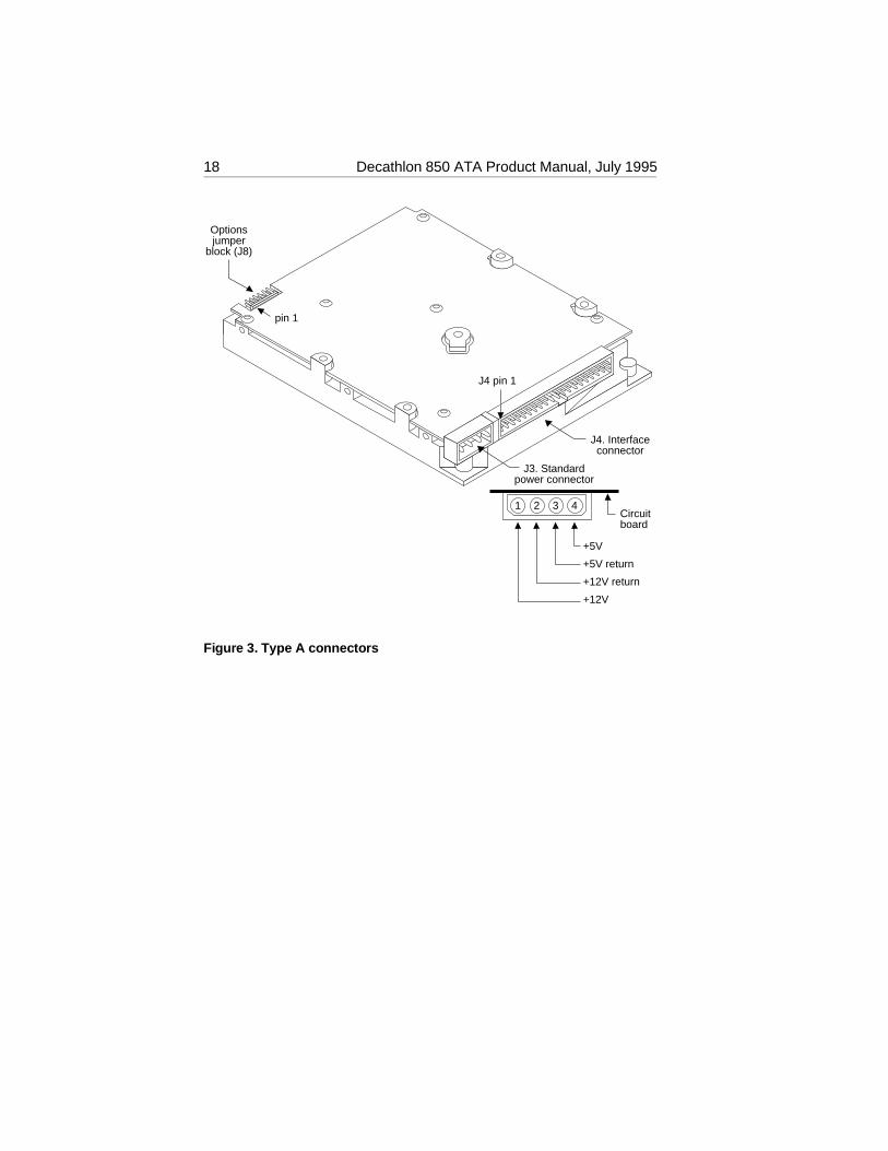
Options jumper
block (J8)
J4 pin 1
J3. Standard power connector
+5V
+5V return
+12V return
+12V
1 2 3 4Circuit board
J4. Interface connector
pin 1
Figure 3. Type A connectors
18 Decathlon 850 ATA Product Manual, July 1995

Circuit board side up
9
10
7
8
5
6
3
4
1
2
One drive only
Drive is master; slave is present
Drive is slave when another drive is present;
Cable select
Remote LED connection pin 7 (–), pin 8 (+)
Spares
12
11
Master/slave timing protocol. Makes drive compatible with some drives as a slave.
Dual-drive emulation
Options jumper block (J8)
Figure 4. Type A configuration settings
Decathlon 850 ATA Product Manual, July 1995 19

Options jumper block
J4 pin 1
pin 1
J3. Standard power connector
+5V +5V return +12V return +12V
1 2 3 4 Circuit board
J4. Interface connector
Figure 5. Type B connectors
20 Decathlon 850 ATA Product Manual, July 1995
Options jumper block
Circuit board side up
11
12
9
10
7
8
5
6
3
4
13
14
1
2
15
16
17
18
19
20
21
22
33
34
31
32
29
30
27
28
25
26
23
24
One drive only
Drive is master; slave is presentDrive is slave
Cable select
Remote LED connection pin 9 (–), pin 10 (+)
Spares
Dual-drive emulation
Note. All other pins are reserved. Do not use them.
Figure 6. Type B configuration settings
Decathlon 850 ATA Product Manual, July 1995 21

2.4.4 Dual-drive emulation
Dual-drive emulation is a feature designed into drives with physicalcapacities greater than 528 Mbytes for computers whose BIOS limit theeffective drive capacity to 528 Mbytes. This feature splits the drive intotwo logical drives with capacities the computer can manage. The onedrive emulates two drives. Each logical drive is assigned a drive type inSystem Setup and must be partitioned and formatted independently. Asecond, physical drive cannot be used when dual-drive emulation isinvoked.
Note. Dual-drive emulation cannot be used in computers that implementthe cable-select configuration.
2.4.5 Remote LED connection
You can attach a remote LED cable to the options jumper block (J8) usingthe pins shown in the drawings. The jumper block is designed to accepta 2-mm connector. It may be necessary for you to replace the currentconnector on the LED cable. Use Seagate part number 13211-001 or anequivalent for the replacement jumper.
2.4.6 Cable-select option
Computers that use the cable-select method for determining the masterand slave drive do so by selecting or deselecting pin 28, CSEL, on theinterface bus. Master and slave drives are determined by their physicalposition on the bus:
• The drive plugged into the I/O connector that carries the CSEL signalis the master.
• The drive plugged into the I/O connector that does not carry the CSELsignal is the slave.
To configure the ST5850A for computers using cable select, refer toFigure 4 on page 19 for Type A drives or Figure 6 on page 21 for TypeB drives. Figure 7 shows how the drives are connected to the interfacecable in computers using cable-select.
22 Decathlon 850 ATA Product Manual, July 1995

2.5 Mounting the drive
You can mount the drive in any orientation. Mount it securely in thecomputer using either the bottom or side mounting holes as describedbelow. Position the drive so that you do not strain or crimp the cables.Figure 8 on page 24 shows the drive’s dimensions, including the sideand bottom mounting holes.
Bottom mounting holes. Insert 6-32 UNC-2A mounting screws in thefour available bottom mounting holes. Do not insert the screws more than0.20 inches (6 turns) into the drive frame.
Side mounting holes. Insert 6-32 UNC-2A mounting screws in any twoof the side mounting holes on each side of the drive. If you have a TypeA drive, do not insert the screws more than 0.240 inches (7 turns) intothe drive frame. If you have a Type B drive, do not insert the screws morethan 0.200 inches (6 turns) into the drive frame.
Caution. To avoid damaging the drive:
• Use mounting screws of the correct size and length.
• Gently tighten the mounting screws—do not apply more than 6inch-pounds of torque.
Master
Line 28 is open
CSELsignalline
Computer
Slave
Pin 28 is grounded at computer
Figure 7. Connecting cable-selected devices
Decathlon 850 ATA Product Manual, July 1995 23

In the following figure, all dimensions are in inches and millimeters (mm).
5.000 +0.000 −0.020 (127.000 +0.000 −0.508)
1.985 ± 0.020 (50.419 ± 0.508)
1.750 ± 0.010 (44.450 ± 0.254)
3.75
0 ±
0.01
0 (9
5.25
0 ±
0.25
4)
4.02
0 m
ax (
102.
108)
0.748 max (19.000)
2.362 ± 0.010 (59.995. ± 0.254)
0.240 ± 0.020 (6.096 ± 0.508)
4.000 ± 0.020 (101.60 ± 0.508)
0.250 ± 0.010 (6.350 ± 0.254)
Six 6-32 UNC-2B threaded holes Max screw insertion depth: 0.20 inches
Four 6-32 UNC-2B threaded holes Max screw insertion depth: 0.20 inches
Figure 8. Mounting dimensions
24 Decathlon 850 ATA Product Manual, July 1995

3.0 ATA interfaceThe ST5850A uses a Fast ATA-2 interface. The interface is in compli-ance with ANSI ATA (AT Attachment) Interface X3T9.2/143 Rev. 4.0;SFF 8011: ATA Timing Extension for Local Bus Attachments, Rev. 2.0and SFF 8019: Identify Drive Data for Drives Under 8 GB. This sectionlists the ATA commands supported by the drive on pages 27 and 28.Commands and features with specific application for the drive are alsodiscussed in this section. For more information on Seagate’s implemen-tation of the ATA interface and commands, see the Seagate ATAInterface Reference Manual, publication number 36111-xxx.
The ATA interface consists of single-ended, TTL-compatible receiversand drivers using an asynchronous interface protocol. The drivers cansink up to 24 mA and drive a load up to 300 pF. The integrity of the ATAinterface is affected by the interface cable. It is designed to support a40-conductor, nonshielded interface cable with a maximum length of 18inches (0.46 meters).
3.1 ATA interface connector pin assignments
The signal name and signal direction for each I/O connector pin isdescribed in Figure 9 on page 26. For a complete description of eachpin, see the Seagate ATA Interface Reference Manual, publicationnumber 36111-xxx.
Signal names are shown in upper-case letters. If the signal name isfollowed by a minus sign (–), the signal is active low. Otherwise, thesignal is active high.
Decathlon 850 ATA Product Manual, July 1995 25

Reset– Ground
DD7 DD8 DD6 DD9 DD5
DD10 DD4
DD11 DD3
DD12 DD2
DD13 DD1
DD14 DD0
DD15 Ground
(removed) DMARQ Ground DIOW– Ground DIOR– Ground IORDY CSEL
DMACK– Ground INTRQ
IOCS16– DA1
PDIAG– DA0 DA2
CS1FX– CS3FX– DASP–
Ground
*Drive-to-drive signals
Host
28 34 39
Drive 0 (master)
Drive 1 (slave)
28 34 39
28 34 39
CSEL PDIAG– DASP–
1 2 3 4 5 6 7 8 9 10 11 12 13 14 15 16 17 18 19 20 21 22 23 24 25 26 27 28 29 30 31 32 33 34 35 36 37 38 39 40
Host Reset Ground Host Data Bus Bit 7 Host Data Bus Bit 8 Host Data Bus Bit 6 Host Data Bus Bit 9 Host Data Bus Bit 5 Host Data Bus Bit 10 Host Data Bus Bit 4 Host Data Bus Bit 11 Host Data Bus Bit 3 Host Data Bus Bit 12 Host Data Bus Bit 2 Host Data Bus Bit 13 Host Data Bus Bit 1 Host Data Bus Bit 14 Host Data Bus Bit 0 Host Data Bus Bit 15 Ground (No Pin) DMA Request Ground Host I/O Write Ground Host I/O Read Ground I/O Channel Ready Cable Select DMA Acknowledge Ground Host Interrupt Request Host 16 Bit I/O Host Address Bus Bit 1 Passed Diagnostics Host Address Bus Bit 0 Host Address Bus Bit 2 Host Chip Select 0 Host Chip Select 1 Drive Active/ Drive 1 Present Ground
Host
1 2 3 4 5 6 7 8 9
10 11 12 13 14 15 16 17 18 19 20 21 22 23 24 25 26 27 28 29 30 31 32 33
*34 35 36 37 38
*39
40
Drive
NC
Figure 9. ATA interface connector pin assignments
26 Decathlon 850 ATA Product Manual, July 1995

3.2 Command set
This section lists all of the ATA commands the ST5850A uses. Com-mands whose implementation is specific for the drive are discussed inthis manual. For information on Seagate’s implementation on the othersupported commands, refer to the Seagate ATA Interface ReferenceManual, publication number 36111-xxx. Additional information on FastATA-related features is provided by the Small Form Factor specification,SFF-8011 Rev 1.1, September 18, 1993.
The following table lists all commands implemented in the ST5850Adrive. The table uses the following abbreviations:
FR Features register
SC Sector Count register
SN Sector Number register
CY Cylinder register
DH Drive/Head register
n This register does not contain a valid parameter for thiscommand.
y This register contains a valid parameter for this command. Inthe Drive/Head register, both the drive and head parametersare valid for this command.
D The Drive/Head register contains a valid drive parameter forthis command. The head parameter is not valid for thiscommand.
Command name Commandcode (in hex)
Parameters used
FR SC SN CY DH
Active and Set Idle Timer FB n y n n D
Active Immediate F9 n n n n D
Check Idle Mode FD n y n n D
Check Power Mode 98, E5 n y n n D
Execute Drive Diagnostics 90 n n n n D
Format Track 50 n y n y y
Identify Drive EC n n n n D
Idle 97, E3 n y n n D
continued
Decathlon 850 ATA Product Manual, July 1995 27

Command name Commandcode (in hex)
Parameters used
FR SC SN CY DH
Idle and Set Idle Timer FA n y n n D
Idle Immediate 95, F8, E1 n n n n D
Initialize Drive Parameters 91 n y n n y
Read DMA4 C8, C9 — y y y y
Read Long4 22, 23 n y y y y
Read Multiple C4 n y y y y
Read Sector4 20, 21 n y y y y
Read Sector Buffer E4 n n n n D
Read Verify Sector4 40, 41 n y y y y
Recalibrate 1X n n n n D
Seek 7X n n y y y
Set Features EF y n n n D
Set Multiple Mode C6 n y n n D
Sleep 99, E6 n n n n D
Standby 96, E2 n n n n D
Standby Immediate 94, E0 n n n n D
Write DMA4 CA, CB — y y y y
Write Long4 32, 33 n y y y y
Write Multiple C5 n y y y y
Write Sector4 30, 31 n y y y y
Write Sector Buffer E8 n n n n D
continued from previous page
4. With retry and without retry commands supported
28 Decathlon 850 ATA Product Manual, July 1995
3.2.1 Identify Drive command (EC H)
The parameters for the drive are listed in the table below. The SeagateATA Interface Reference Manual, publication number 36111-xxx, de-scribes the Identify Drive command in detail.
Word Description Value
0 Configuration 047AH0400H Disc transfer rate
> 10 Mbytes per second0040H Fixed drive0020H Spindle motor control
option implemented0010H Head switch time
> 15 µsec0008H Not MFM encoded0002H Hard sectored
1 Default cylinders See Sections 1.1.1 and 1.1.1 forvalue appropriate to model.
2 Reserved 0
3 Default heads 16
4 Bytes per track 8EBCH (36540 decimal)(unformatted)
5 Bytes per sector 244H (580 decimal)(unformatted)
6 Default sectors pertrack
63
7–9 Vendor-unique 0000H
10–19 Serial number Drive-unique: 20 ASCII characters
20 Buffer type 0003H Multisector with caching
21 Buffer size (numberof 512-byte sectors)
0200H
22 ECC bytes (R/WLong)
0004H
23–26 Firmware revision Drive-dependent: 8 ASCIIcharacters
27–46 Model number Drive-dependent: 40 ASCIIcharacters
continued
Decathlon 850 ATA Product Manual, July 1995 29
Word Description Value
47 Maximum Sectorsper interrupt per R/WMultiple command
8020H R/W Multiple supported;32 sectors per block
48 Double word I/O 0000H Not supported
49 Capabilities 0B01H IORDY, DMA, LBAsupported
50 Reserved 0000H
51 PIO timing mode 0200H
52 DMA timing mode 0201H Multiword DMA mode 2supported
53 Current valid 0003H, 54–58, 64–70 valid
54 Current cylinders 1,656
55 Current heads 16
56 Current sectors pertrack
63
57–58 Current sectors 1,669, 248 (CHS)
59 Current multiplemode
0000H
60–61 LBA total sectors 1,669, 260
62 Single-word DMA 0000H No modes are active;no modes are supported.
63 Multiword DMA 0107H Mode 0 is active; modes0, 1 and 2 are supported.
64 Advanced PIO 0003H Modes 3 and 4 aresupported.
65 Minimum multiwordDMA transfer perword
120 nsec
66 Recommendedmultiword DMAtransfer per word
120 nsec
67 Minimum PIOtransfer withoutIORDY
240 nsec
continued from previous page
30 Decathlon 850 ATA Product Manual, July 1995

Word Description Value
68 Minimum PIOtransfer with IORDY
120 nsec
69–127 Reserved xxxxH
128–159 Seagate-reserved xxxxH
160– 255 Reserved xxxxH
3.2.2 Set Features command (EF H)
The Set Features command (command code EFH) allows the user toenable and disable the multisegmented cache features and to identifythe transfer modes the drive uses. The multisegmented buffer consistsof Read Look-ahead and write-immediate and write-merging features.The table below lists the features supported by the ST5850A. Thefeatures that are set to default by the factory are indicated in the Featurecolumn.
Feature Value Feature
02H Enable write immediate and write merging(default)
03H Set transfer mode
55H Disable read look ahead cache
82H Disable write immediate and write merging
AAH Enable read look-ahead (default)
To use the command:
1. Write the feature value to the Features register.
2. Write the Set Features command to the command register.
Note. If the value in the Features register is not supported or is invalid,the drive posts an Aborted Command error (04).
The factory-default values are restored at power-on or after a hard reset.
Decathlon 850 ATA Product Manual, July 1995 31

3.2.2.1 Multisegmented cache buffer
The drive uses a 256-Kbyte multisegmented cache buffer to improveperformance by eliminating access times under certain conditions.
Read look-ahead. The drive uses the read segments to store additionallogical sectors, after the last requested sector, into a buffer before thecomputer requests the additional sectors. The cache buffer stores datafrom the start of a read until the buffer segment is full or until anothercommand is received.
Write immediate and write merging. Segments of the cache arereserved for write data. The drive will accept contiguous and sequentialwrite commands and execute them as one command. When the bufferhas received all of the data, the drive issues a write complete and writesthe data to the disc. The last data written by the drive is retained in thebuffer for future write or read use.
3.2.2.2 PIO and DMA data-transfer modes
You can set the multiword DMA mode and identify the PIO data-transfermechanism and transfer mode with the Set Features command. To setthe multiword DMA mode:
1.1. Write Set Features command value 03H (Set Data Transfer mode) tothe Features register.
2. Write a transfer types value to the Sector Count register. The upper5 bits of this value define the type of data transfer, and the lower 3bits encode the mode value.
This changes word 63 of the Identify Drive command to the mode youenter in the Sector Count register.
The following table identifies allowable transfer-types values:
Data-transfer mechanism Transfer-types value
Mechanism name Mode value
DataUpper 5 bits Lower 3 bits
PIO Transfer Mode (default:Set PIO Mode = 2) 2 00000 000
PIO Transfer Mode: Set PIO Mode = 2 2 00000 001
PIO Flow Control TransferMode: Set PIO Mode = 0 0 00001 000
32 Decathlon 850 ATA Product Manual, July 1995

Data-transfer mechanism Transfer-types value
Mechanism name Mode value
DataUpper 5 bits Lower 3 bits
PIO Flow Control TransferMode: Set PIO Mode = 1 1 00001 001
PIO Flow Control TransferMode: Set PIO Mode = 2 2 00001 010
PIO Flow Control TransferMode: Set PIO Mode = 3 3 00001 011
PIO Flow Control TransferMode: Set PIO Mode = 4 4 00001 100
Multiword DMA Mode 0 00100 000
Multiword DMA Mode 1 00100 001
Multiword DMA Mode 2 00100 010
Reserved — 01000 nnn
If the drive does not support a commanded mode, it returns an 04 AbortedCommand error.
3.2.3 Sleep command (99 H, E6H)
When the computer issues the Sleep command, the drive enters Standbymode. The drive may return an interrupt before the transition to Standbymode is complete. A separate Sleep mode is not supported.
Decathlon 850 ATA Product Manual, July 1995 33


Appendix. Timing diagramsWithout IORDY, the drive operates at programmed I/O timing specifica-tions, as shown below.
Time Description Min Max
T0 Cycle time 240 nsec —
T1 Drive address (CS1FX–, CS3FX–,DA0, DA1 and DA2) valid and DIOR– and DIOW– setup
25 nsec —
T2 DIOW– or DIOR– pulse width 70 nsec —
T3 DIOW– data setup 20 nsec —
T4 DIOW– data hold 10 nsec —
T5 DIOR– data setup 20 nsec —
T6 DIOR– data hold 5 nsec —
T7 Address valid until IOCS16– isasserted — 20 nsec
T8 Address invalid to IOCS16– tristate — 5 nsec
T9 DIOR– false to read data hold — 20 nsec
Address valid
DIOR− and DIOW−
Write data valid
Read data valid
IOCS16−
T7
T1
T2
T3
T5 T6
T4
T0
T9 T8
Figure 10. Programmed I/O timing without IORDY
Decathlon 850 ATA Product Manual, July 1995 35

When using IORDY, the drive operates at programmed timing specifica-tions, as shown below.
Time Description Min Max
T0 Cycle time 120 nsec —
T1 Address valid until IOCS16– is asserted — 20 nsec
T2 Drive address (CS1FX–, CS3FX–,DA0, DA1 and DA2) valid before DIOR–or DIOW– setup
25 nsec —
T3 IORDY setup time — —
T4DIOW– or DIOR– pulse width (8-bit) 70 nsec —
DIOW– or DIOR– pulse width (16-bit) 70 nsec —
T5 IORDY pulse width — 1,250nsec
T6 DIOW– data setup 20 nsec —
T7 DIOR– data setup 20 nsec —
T8 DIOR– data hold 5 nsec —
T9 DIOW– data hold 10 nsec —
T10 DIOW– or DIOR– to address valid hold 5 nsec —
T11 Address invalid until IOCS16– isnegated — 5 nsec
Address valid
DIOR− or DIOW−
Write data valid
Read data valid
IOCS16−
T1
T0
T2
T4
T6
T7
T9
T8
T11T10
T3
IORDY
T5
Address valid
DIOR− or DIOW−
Write data valid
Read data valid
IOCS16−
T1
T0
T2
T4
T6
T7
T9
T8
T11T10
T3
IORDY
T5
Figure 11. Programmed I/O timing with IORDY
36 Decathlon 850 ATA Product Manual, July 1995

The drive operates at multiword DMA mode 2 timing specifications, asshown below.
Time Description Min Max
T0 Cycle time 120 nsec —
TD DIOW– or DIOR– pulse width (16-bit) 70 nsec —
TE DIOR– data access — —
TF DIOR– data hold 5 nsec —
TG DIOW– data setup 20 nsec —
TH DIOW– data hold 10 nsec —
TI DMACK– to DIOR– or DIOW– setup 0 nsec —
TJ DIOR– or DIOW– to DMACK– hold 5 nsec —
TKR DIOR– negated pulse width 25 nsec —
TKW DIOW– negated pulse width 25 nsec —
TLR DIOR– to DMARQ delay — 35 nsec
TLW DIOW– to DMARQ delay — 25 nsec
DMACK−
DMARQ
T0
DIOR− or DIOW−
Read data valid
Write data valid
TK
TG
TDTI TJ
TH
TF
TL
TE
Figure 12. Multiword DMA timing
Decathlon 850 ATA Product Manual, July 1995 37


Seagate Technology, Inc.920 Disc Drive, Scotts Valley, California 95066, USA
Publication Number: 36326-001, July 1995, Printed in USA