at commands examples - u-blox
TRANSCRIPT
AT Commands Examples Examples for u-blox cellular modules Application Note
Abstract
This document provides detailed examples of how to use AT commands with u-blox cellular modules.
www.u-blox.com
UBX-13001820 - R11

AT Commands Examples - Application Note
UBX-13001820 - R11
Page 2 of 129
Document Information
Title AT Commands Examples
Subtitle Examples for u-blox cellular modules
Document type Application Note
Document number UBX-13001820
Revision, date R11 22-Sep-2016
Document status Early Production Information
Document status explanation
Objective Specification Document contains target values. Revised and supplementary data will be published later.
Advance Information Document contains data based on early testing. Revised and supplementary data will be published later.
Early Production Information Document contains data from product verification. Revised and supplementary data may be published later.
Production Information Document contains the final product specification.
This document applies to the following products:
Product name
LEON-G1 series
SARA-G3 series
LISA-U2 series
SARA-U2 series
TOBY-L2 series
MPCI-L2 series
u-blox reserves all rights to this document and the information contained herein. Products, names, logos and designs described herein may in whole or in part be subject to intellectual property rights. Reproduction, use, modification or disclosure to third parties of this
document or any part thereof without the express permission of u-blox is strictly prohibited.
The information contained herein is provided “as is” and u-blox assumes no liability for the use of the information. No warranty, either express or implied, is given, including but not limited, with respect to the accuracy, correctness, reliability and fitness for a particular
purpose of the information. This document may be revised by u-blox at any time. For most recent documents, please visit www.u-blox.com.
Copyright © 2016, u-blox AG
AT Commands Examples - Application Note
UBX-13001820 - R11 Early Production Information Contents
Page 3 of 129
Contents
Contents .............................................................................................................................. 3
1 Introduction .................................................................................................................. 8
2 AT command response parser ..................................................................................... 9
2.1 Handle AT command response ............................................................................................................. 9
2.2 Handle unsolicited result code ............................................................................................................ 10
2.3 Best practices ...................................................................................................................................... 11
3 Parameters storing ..................................................................................................... 12
4 Network registration and configuration .................................................................. 13
4.1 Steps for registering the module with a GSM/UMTS network ............................................................. 13
4.1.1 Preliminary operations ................................................................................................................. 13
4.1.2 Network registration: GSM module ............................................................................................. 13
4.1.3 Network registration: UMTS module ........................................................................................... 14
4.1.4 Network registration: LTE module ............................................................................................... 19
4.1.5 Network operator configuration through +UMNOCONF AT command ........................................ 22
4.1.6 PLMN list extension +UMNOPLMN: LTE module .......................................................................... 24
4.2 Network registration flow-chart .......................................................................................................... 25
5 GPRS connection......................................................................................................... 28
5.1 External PDP context handling ............................................................................................................ 28
5.1.1 External PDP context definition and activation ............................................................................. 28
5.2 Secondary PDP context definition and activation in ROUTER mode ..................................................... 33
5.3 Internal PDP context activation ........................................................................................................... 35
5.4 Context deactivation .......................................................................................................................... 36
5.4.1 Context deactivation by the network ........................................................................................... 36
5.4.2 Context deactivation by the module ............................................................................................ 36
5.5 Reading and setting of counters of sent and received PSD data .......................................................... 36
5.6 DoCoMo PS PUSH context manual activation ..................................................................................... 37
5.7 DoCoMo PS PUSH context manual reject ............................................................................................ 38
5.8 Data connection management ............................................................................................................ 39
5.8.1 Network policy: no IP connectivity on the default bearer ............................................................. 39
5.8.2 Network policy: only one bearer for each APN can be activated .................................................. 40
5.8.3 Network policy: more than one bearer with the same APN can be activated ............................... 40
5.9 Network connectivity in ROUTER mode .............................................................................................. 42
5.9.1 2G/3G case ................................................................................................................................. 42
5.9.2 4G case ....................................................................................................................................... 42
5.9.3 Set up the connection on Windows 7 .......................................................................................... 43
5.10 Network connectivity (BRIDGE mode) .............................................................................................. 47
5.10.1 2G/3G case ................................................................................................................................. 47

AT Commands Examples - Application Note
UBX-13001820 - R11 Early Production Information Contents
Page 4 of 129
5.10.2 4G case ....................................................................................................................................... 47
5.10.3 Set up the connection on Windows 7 .......................................................................................... 48
5.10.4 Using sockets on an already activated PDP context ...................................................................... 54
5.10.5 PDP context activation by means of +UPSDA, impact of <PDP_type> on address ......................... 56
6 Dynamic DNS AT command ....................................................................................... 57
7 TCP/IP AT commands .................................................................................................. 57
7.1 Socket connect ................................................................................................................................... 57
7.2 Socket listening .................................................................................................................................. 58
7.3 Socket write ....................................................................................................................................... 58
7.3.1 Binary mode ................................................................................................................................ 58
7.3.2 Base syntax.................................................................................................................................. 59
7.3.3 Queue FULL ................................................................................................................................. 59
7.3.4 GSM network coverage lost ........................................................................................................ 59
7.4 Socket operations with "Keep Alive" option ....................................................................................... 61
7.5 Socket read ........................................................................................................................................ 62
7.6 Socket state ........................................................................................................................................ 63
7.7 Socket close ........................................................................................................................................ 64
7.8 Direct link ........................................................................................................................................... 64
7.8.1 Enter and exit from Direct link mode ........................................................................................... 64
7.8.2 Closing a connection ................................................................................................................... 65
7.8.3 Connection closed by remote host .............................................................................................. 66
7.9 Socket Always On ............................................................................................................................... 66
7.9.1 Client configuration .................................................................................................................... 66
7.9.2 Client operation .......................................................................................................................... 66
7.9.3 Server configuration .................................................................................................................... 67
7.9.4 Server operation .......................................................................................................................... 67
7.10 IP Change notification ..................................................................................................................... 67
7.11 Verizon socket configuration ........................................................................................................... 68
7.12 AT&T socket configuration .............................................................................................................. 69
8 UDP/IP AT commands ................................................................................................. 70
8.1 Socket write (+USOST) ........................................................................................................................ 70
8.2 Socket read (+USORF) ......................................................................................................................... 70
8.3 Socket write (+USOWR) ...................................................................................................................... 71
8.4 Socket read (+USORD) ........................................................................................................................ 72
9 FTP AT commands ...................................................................................................... 73
9.1 Direct link ........................................................................................................................................... 75
9.1.1 Retrieve a file from FTP server ...................................................................................................... 75
9.1.2 Aborting retrieve file request ....................................................................................................... 76
9.1.3 Store a file on FTP server ............................................................................................................. 76
9.1.4 About "+++" escape sequence usage ......................................................................................... 77
9.2 Using secure option ............................................................................................................................ 77

AT Commands Examples - Application Note
UBX-13001820 - R11 Early Production Information Contents
Page 5 of 129
10 SMTP AT commands ................................................................................................... 78
11 ODIS implementation ................................................................................................. 80
11.1 OMA-DM client initialization ........................................................................................................... 80
11.2 ODIS nodes ..................................................................................................................................... 81
11.3 Module FW update notification ....................................................................................................... 82
11.4 OMA-DM client activity reporting .................................................................................................... 83
12 HTTP AT commands .................................................................................................... 84
12.1 Using secure option ........................................................................................................................ 85
12.1.1 Importing a X.509 certificate ....................................................................................................... 85
12.1.2 Examples about certificate validation levels .................................................................................. 89
12.1.3 Data security and integrity ........................................................................................................... 92
12.2 HTTP POST ...................................................................................................................................... 93
12.3 HTTP cookies ................................................................................................................................... 94
13 Network jamming detection AT commands ............................................................. 95
13.1 Jamming detection threshold and number of carriers evaluation ..................................................... 95
13.1.1 Example 1: 2G threshold and number of carriers evaluation ........................................................ 95
13.2 Jamming detection in 2G network .................................................................................................. 96
13.2.1 Example 1: all the available 2G carriers jammed .......................................................................... 96
13.3 Jamming detection in 3G network .................................................................................................. 96
13.3.1 Example 1: all the available 3G carriers jammed .......................................................................... 96
13.4 Jamming detection in 2G/3G network ............................................................................................ 97
13.4.1 Example 1: all the available 2G and 3G carriers jammed .............................................................. 97
13.5 Advanced jamming detection in 2G network .................................................................................. 97
13.5.1 Example 1: all the available 2G carriers jammed .......................................................................... 97
13.5.2 Example 2: all the available 2G carriers jammed; selected PLMN not retrieved from IMSI ............. 98
13.5.3 Example 3: not jammed 2G carrier(s) are not part of the selected PLMN ...................................... 98
14 Cell lock AT commands .............................................................................................. 99
14.1 Cell lock in single mode .................................................................................................................. 99
14.1.1 Cell lock in 2G network: normal mode ........................................................................................ 99
14.1.2 Cell lock in 2G network: extended mode ..................................................................................... 99
14.1.3 Cell lock in 2G network: normal mode ...................................................................................... 100
14.1.4 Cell lock in 2G network: extended mode ................................................................................... 100
14.1.5 Cell lock in 3G network: normal mode ...................................................................................... 100
14.1.6 Cell lock in 3G network: extended mode ................................................................................... 101
14.1.7 Cell lock in 3G network: extended + redirection mode .............................................................. 101
14.1.8 Cell lock in 4G network: normal mode ...................................................................................... 102
14.1.9 Cell lock in 4G network: extended mode ................................................................................... 102
14.1.10 Cell lock in 4G network: extended + redirection mode .......................................................... 102
14.2 Cell lock in multi mode ................................................................................................................. 103
14.2.1 Cell lock in dual-mode: normal mode ........................................................................................ 103
14.2.2 Cell lock in dual-mode: extended mode .................................................................................... 103

AT Commands Examples - Application Note
UBX-13001820 - R11 Early Production Information Contents
Page 6 of 129
14.2.3 Cell lock in dual-mode: extended + redirection mode ................................................................ 104
14.2.4 Cell lock in tri-mode: normal mode ........................................................................................... 104
14.2.5 Cell lock in tri-mode: extended mode ........................................................................................ 104
14.2.6 Cell lock in tri-mode: extended + redirection mode ................................................................... 105
15 ADC AT commands ................................................................................................... 106
16 GPIO AT commands .................................................................................................. 106
17 Multiplexer AT commands ....................................................................................... 107
18 File system AT commands ........................................................................................ 108
19 SIM toolkit ................................................................................................................ 109
19.1 Profile download ........................................................................................................................... 109
19.2 Proactive SIM ................................................................................................................................ 109
19.3 Example ........................................................................................................................................ 111
19.3.1 Enable the SAT and terminal response ....................................................................................... 111
19.3.2 Changing the terminal profile .................................................................................................... 111
19.3.3 Entering SAT menu and selecting an item ................................................................................. 112
19.3.4 Call setup .................................................................................................................................. 113
19.3.5 Refresh proactive command handling ........................................................................................ 114
19.3.6 Envelope: idle screen available ................................................................................................... 115
20 SMS AT commands ................................................................................................... 116
20.1 Read all messages or one single message ...................................................................................... 116
20.2 Delete one single message or multiple messages ........................................................................... 117
20.3 Write and/or send one single message .......................................................................................... 117
20.4 Read all messages or one single message (concatenated SMS related commands) ........................ 118
20.5 Write and/or send a concatenated SMS message .......................................................................... 119
21 SIM lock AT commands ............................................................................................ 121
21.1 SIM lock activation and deactivation ............................................................................................. 121
21.2 SIM lock enabling and activation ................................................................................................... 121
22 SIM Access Profile (SAP) AT commands .................................................................. 122
22.1 SAP activation ............................................................................................................................... 122
22.2 SAP deactivation ........................................................................................................................... 123
23 USB profile configuration ........................................................................................ 124
23.1 High throughput profile ................................................................................................................ 124
23.2 Fairly back-compatible profile ........................................................................................................ 124
23.3 Low/Medium throughput profile ................................................................................................... 125
Appendix ........................................................................................................................ 126
A List of acronyms ....................................................................................................... 126

AT Commands Examples - Application Note
UBX-13001820 - R11 Early Production Information Contents
Page 7 of 129
Related documents ........................................................................................................ 128
Revision history .............................................................................................................. 128
Contact ............................................................................................................................ 129

AT Commands Examples - Application Note
UBX-13001820 - R11 Early Production Information Introduction
Page 8 of 129
1 Introduction This document provides examples of using AT commands. See u-blox AT Commands Manual [1] for the AT command descriptions. The following symbols are used to highlight important information within the document:
An index finger points out key information pertaining to integration and performance.
A warning symbol indicates actions that could negatively impact or damage the module.
These icons will be used to indicate applicability to the related products:
: LEON-G1 series
: LISA-U2 series
: SARA-G3 series
: SARA-U2 series
: TOBY-L2 series
If the subsection applies to a specific product, the related icon will be provided there.
The MPCI-L2 series provides the same feature set as the TOBY-L2 series. Therefore the "TOBY-L2" icon also refers to MPCI-L2 series.
The correctness of the networking examples depends on the availability of the website and FTP site. Be sure to use a valid website (or FTP site).
TOBY-L2
SARA-U
SARA-G
LISA-U
LEON-G

AT Commands Examples - Application Note
UBX-13001820 - R11 Early Production Information AT command response parser
Page 9 of 129
2 AT command response parser
The scope of this section is to give some hints about how to develop a proper AT parser and how to handle the AT command replies and the URCs.
In this document the following naming conventions are used:
DCE (Data Communications Equipment) or MT (Mobile Terminal) is the u-blox cellular module
DTE (Data Terminal Equipment) or TE (Terminal Equipment) is the terminal that sends the command to the module
2.1 Handle AT command response
When a generic AT command is issued, depending on the command sent, there may or may not be an Information Text Response. At the end there is always the Final Result Code, which marks the end of the command.
The following shows responses that can occur from DTE point of view:
Wait for the command response
o Actions to be taken when a timeout expires
Response to the command
o OK o +<cmd>: ...
OK
Response to particular commands. For further details see "Information text responses and result codes" section in the u-blox AT Commands Manual [1]
o CONNECT o NO CARRIER o BUSY o NO ANSWER o CONNECT o > o @
Errors
o +CME ERROR: ... o +CMS ERROR: ... o ERROR
Command aborted
o ABORTED
o OK
TOBY-L2 / MPCI-L2 modules do not support the aborting of any AT commands.
SARA-G LEON-G
SARA-U LISA-U
TOBY-L2 SARA-U SARA-G LISA-U LEON-G
AT Commands Examples - Application Note
UBX-13001820 - R11 Early Production Information AT command response parser
Page 10 of 129
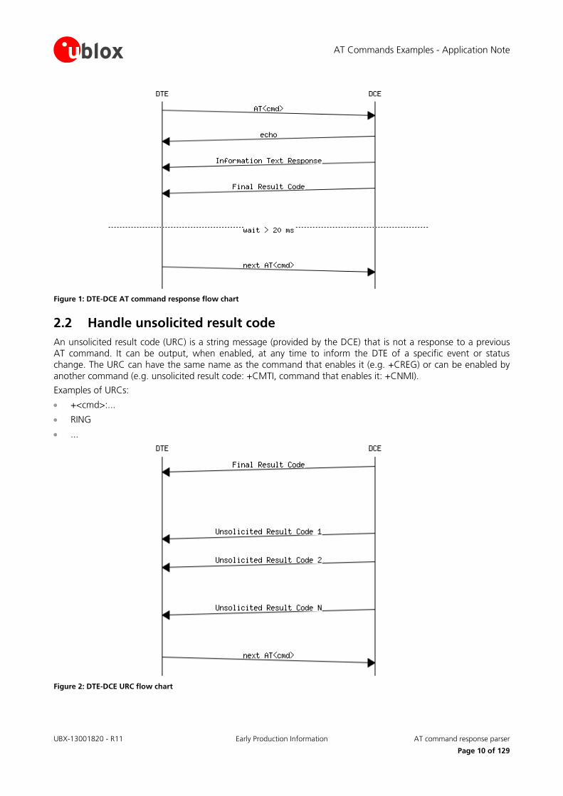
Figure 1: DTE-DCE AT command response flow chart
2.2 Handle unsolicited result code
An unsolicited result code (URC) is a string message (provided by the DCE) that is not a response to a previous AT command. It can be output, when enabled, at any time to inform the DTE of a specific event or status change. The URC can have the same name as the command that enables it (e.g. +CREG) or can be enabled by another command (e.g. unsolicited result code: +CMTI, command that enables it: +CNMI).
Examples of URCs:
+<cmd>:...
RING
...
Figure 2: DTE-DCE URC flow chart
AT Commands Examples - Application Note
UBX-13001820 - R11 Early Production Information AT command response parser
Page 11 of 129
2.3 Best practices
The DTE shall flush the AT channel (i.e. check if there are data waiting to be read) before sending a new AT command
The DTE shall detect/process complete lines (see the S3, S4 and V0/V1 settings), so they can be processed with a function that handles responses
The DTE shall handle the case of unexpected spaces or line endings
The DTE shall handle all the URCs: it can simply ignore them (not suggested) or, better, take a proper action
The DTE shall know what answer is expected and shall wait until it is received (i.e. final result code only or information text response + final result code)
The final result code marks the end of an AT command and can be OK, ERROR or ABORTED: when the final result is an error, be sure to handle it before continuing with the next AT command
The information text response format is command specific. The DTE will need explicit handling for each one. It is suggested to consult the u-blox AT command manual [1]
It is suggested not to strictly parse information text responses but to check if they contain interesting keywords and/or parameters
The DTE shall know if the issued AT command can be aborted or not
Some AT commands could output the final result code after some seconds, in this case check on AT manual for the suggested estimated response time. If the timeout expires then a decision should be taken accordingly: e.g. if the command can be aborted then try to abort it, etc ...
It is very useful, for debugging an application, to log all the command lines sent to the DCE and what is received from it
Create a state machine for the AT parser (i.e. idle, waiting_response, data_mode)
The DTE shall wait some time (the recommended value is at least 20 ms) after the reception of an AT command final response or URC before issuing a new AT command to give the module the opportunity to transmit the buffered URCs. Otherwise the collision of the URCs with the subsequent AT command is still possible
The DTE shall be aware that, when using a serial port without HW flow control, the first character is used to wake up the module from power saving
AT Commands Examples - Application Note
UBX-13001820 - R11 Early Production Information Parameters storing
Page 12 of 129
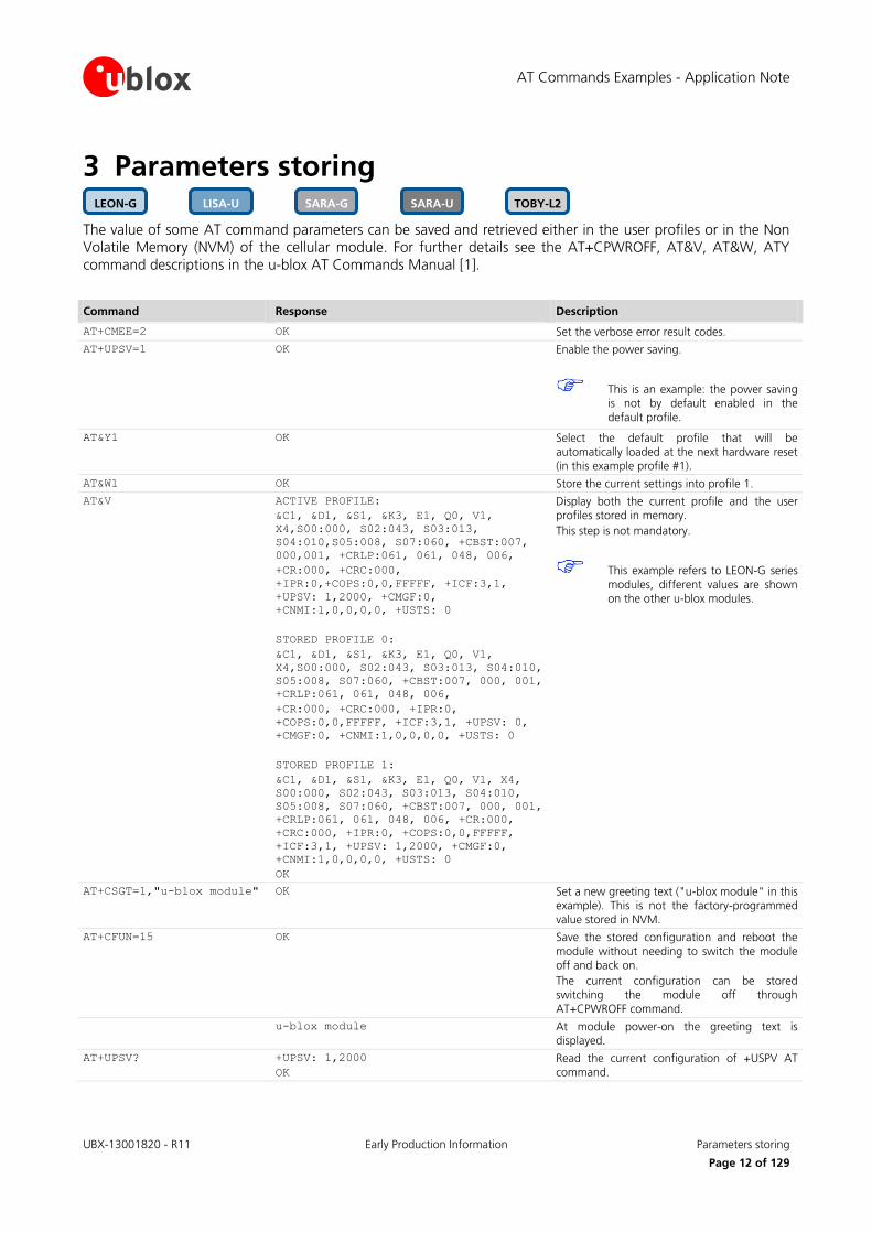
3 Parameters storing
The value of some AT command parameters can be saved and retrieved either in the user profiles or in the Non Volatile Memory (NVM) of the cellular module. For further details see the AT+CPWROFF, AT&V, AT&W, ATY command descriptions in the u-blox AT Commands Manual [1].
Command Response Description
AT+CMEE=2 OK Set the verbose error result codes.
AT+UPSV=1 OK Enable the power saving.
This is an example: the power saving is not by default enabled in the
default profile.
AT&Y1 OK Select the default profile that will be automatically loaded at the next hardware reset (in this example profile #1).
AT&W1 OK Store the current settings into profile 1.
AT&V ACTIVE PROFILE:
&C1, &D1, &S1, &K3, E1, Q0, V1,
X4,S00:000, S02:043, S03:013,
S04:010,S05:008, S07:060, +CBST:007,
000,001, +CRLP:061, 061, 048, 006,
+CR:000, +CRC:000,
+IPR:0,+COPS:0,0,FFFFF, +ICF:3,1,
+UPSV: 1,2000, +CMGF:0,
+CNMI:1,0,0,0,0, +USTS: 0
STORED PROFILE 0:
&C1, &D1, &S1, &K3, E1, Q0, V1,
X4,S00:000, S02:043, S03:013, S04:010,
S05:008, S07:060, +CBST:007, 000, 001,
+CRLP:061, 061, 048, 006,
+CR:000, +CRC:000, +IPR:0,
+COPS:0,0,FFFFF, +ICF:3,1, +UPSV: 0,
+CMGF:0, +CNMI:1,0,0,0,0, +USTS: 0
STORED PROFILE 1:
&C1, &D1, &S1, &K3, E1, Q0, V1, X4,
S00:000, S02:043, S03:013, S04:010,
S05:008, S07:060, +CBST:007, 000, 001,
+CRLP:061, 061, 048, 006, +CR:000,
+CRC:000, +IPR:0, +COPS:0,0,FFFFF,
+ICF:3,1, +UPSV: 1,2000, +CMGF:0,
+CNMI:1,0,0,0,0, +USTS: 0
OK
Display both the current profile and the user profiles stored in memory.
This step is not mandatory.
This example refers to LEON-G series
modules, different values are shown on the other u-blox modules.
AT+CSGT=1,"u-blox module" OK Set a new greeting text ("u-blox module" in this example). This is not the factory-programmed
value stored in NVM.
AT+CFUN=15 OK Save the stored configuration and reboot the
module without needing to switch the module off and back on.
The current configuration can be stored
switching the module off through AT+CPWROFF command.
u-blox module At module power-on the greeting text is displayed.
AT+UPSV? +UPSV: 1,2000
OK
Read the current configuration of +USPV AT command.
TOBY-L2 SARA-U SARA-G LISA-U LEON-G
AT Commands Examples - Application Note
UBX-13001820 - R11 Early Production Information Network registration and configuration
Page 13 of 129
4 Network registration and configuration
4.1 Steps for registering the module with a GSM/UMTS network
Perform the module registration with GSM/UMTS network as follows:
Set the PIN
Perform the network registration
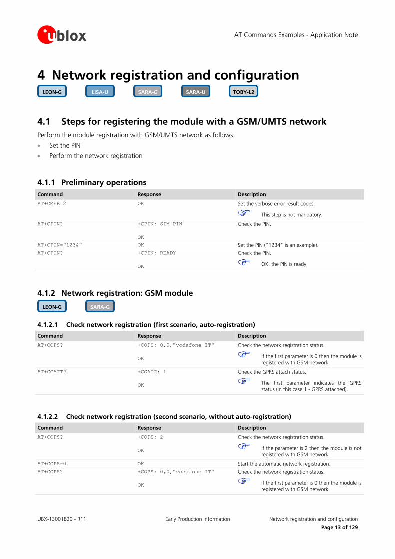
4.1.1 Preliminary operations
Command Response Description
AT+CMEE=2 OK Set the verbose error result codes.
This step is not mandatory.
AT+CPIN? +CPIN: SIM PIN
OK
Check the PIN.
AT+CPIN="1234" OK Set the PIN ("1234" is an example).
AT+CPIN? +CPIN: READY
OK
Check the PIN.
OK, the PIN is ready.
4.1.2 Network registration: GSM module
4.1.2.1 Check network registration (first scenario, auto-registration)
Command Response Description
AT+COPS? +COPS: 0,0,"vodafone IT"
OK
Check the network registration status.
If the first parameter is 0 then the module is registered with GSM network.
AT+CGATT? +CGATT: 1
OK
Check the GPRS attach status.
The first parameter indicates the GPRS status (in this case 1 - GPRS attached).
4.1.2.2 Check network registration (second scenario, without auto-registration)
Command Response Description
AT+COPS? +COPS: 2
OK
Check the network registration status.
If the parameter is 2 then the module is not registered with GSM network.
AT+COPS=0 OK Start the automatic network registration.
AT+COPS? +COPS: 0,0,"vodafone IT"
OK
Check the network registration status.
If the first parameter is 0 then the module is registered with GSM network.
SARA-G LEON-G
TOBY-L2 SARA-U SARA-G LISA-U LEON-G

AT Commands Examples - Application Note
UBX-13001820 - R11 Early Production Information Network registration and configuration
Page 14 of 129
4.1.2.3 Check network registration (third scenario, data only SIMs)
Command Response Description
AT+COPS? +COPS: 0
OK
Check the network registration status.
When using data only SIMs, in some networks AT+COPS? returns the operator
name, in other networks returns only 0, even if the GPRS network registration is
enabled.
AT+CREG? +CREG: 0,3
OK
Check network registration status
AT+CGREG? +CGREG: 0,1
OK
Check GPRS network registration status
AT+UCGOPS? +UCGOPS: 0,0,"00101",2
OK
Check PS (Packet Switched) network registration status
4.1.2.4 GSM band change
Command Response Description
AT+UBANDSEL? +UBANDSEL: 900, 1800
OK
Check the current selected GSM bands.
AT+COPS=2 OK De-register the module from the network. Perform this operation only if the module is registered with the network.
AT+UBANDSEL=850,1900 OK Change the operating GSM bands.
The new configuration is saved in NVM for
future registration attempts.
AT+COPS=0 OK Start the automatic network registration.
4.1.3 Network registration: UMTS module
4.1.3.1 Preliminary information about Radio Access Technology (RAT) configuration
The default RAT configuration is GSM / UMTS dual-mode, with UMTS the preferred access technology.
Command Response Description
AT+URAT? +URAT: 1,2
OK
The default RAT configuration is GSM / UMTS dual-mode Radio Access technology with UMTS preferred access technology. The module can access
both GSM and UMTS networks, where UMTS is the preferred RAT.
Deregister the module from the network with AT+COPS=2 command before changing the RAT configuration.
Power off the module (AT+CPWROFF) to save the RAT configuration in the NVM. After this, switch on the module and repeat the steps listed in section 4.1.1.
SARA-U LISA-U

AT Commands Examples - Application Note
UBX-13001820 - R11 Early Production Information Network registration and configuration
Page 15 of 129
When a new RAT setting is saved in the NVM it is not possible to load the RAT factory-programmed configuration. To restore this perform the following steps:
Command Response Description
AT+COPS=2 OK Deregister the module from the network. Perform this operation only if the module is registered with the network.
AT+URAT=1,2 OK Select GSM / UMTS dual-mode Radio Access technology with UMTS networks preferred.
This is the RAT factory defined configuration.
AT+CPWROFF OK Switch off the module.
4.1.3.2 RAT selection
GSM single mode RAT
Command Response Description
AT+URAT=0,0 OK Select GSM Single Mode Radio Access technology.
AT+URAT? +URAT: 0,0
OK
The module can access only GSM networks.
AT+COPS=0 OK Start automatic network registration.
AT+COPS? +COPS: 0,0,"vodafone IT",0
OK
Check the network registration status.
The last parameter describes which type of RAT (2G or 3G) the module is currently registered to (0 - GSM in
this case).
GSM / UMTS dual-mode RAT
Command Response Description
AT+URAT=1,0 OK Select GSM / UMTS dual-mode Radio Access
technology, GSM is the preferred access technology.
AT+URAT? +URAT: 1,0
OK
With this configuration the module can access both GSM and UMTS networks, GSM is the preferred RAT.
AT+URAT=1,2 OK Select GSM / UMTS dual-mode Radio Access technology, UMTS is the preferred RAT.
AT+URAT? +URAT: 1,2
OK
With this configuration the module can access both GSM and UMTS networks, UMTS is the preferred RAT.
AT+COPS=0 OK Start the automatic network registration.
AT+COPS? +COPS: 0,0,"vodafone IT",2
OK
Check the network registration status.
The last parameter describes which type of RAT (2G or 3G) the module is currently registered to (2 - UMTS in
this case).
AT+COPS? +COPS: 0,0,"vodafone IT",0
OK
The module is also allowed to access GSM networks.
This will be the information text response if it is
registered with GSM service.
UMTS single mode RAT
Command Response Description
AT+URAT=2,2 OK Select UMTS Single Mode Radio Access technology.
AT+URAT? +URAT: 2,2
OK
With this configuration the module can access only UMTS networks.
AT+COPS=0 OK Start the automatic network registration.

AT Commands Examples - Application Note
UBX-13001820 - R11 Early Production Information Network registration and configuration
Page 16 of 129
Command Response Description
AT+COPS? +COPS: 0,0,"vodafone IT",2
OK
Check the network registration status.
The last parameter describes which type of RAT (2G or 3G) the module is currently registered to (2 - UMTS in
this case).
If the module is registered with GSM / UMTS dual-mode (AT+URAT=1,0 or AT+URAT=1,2) it is possible to change the preferred RAT technology but the new setting only takes effect after a period of lost network coverage or if the module is deregistered and re-registered on the network.
Command Response Description
AT+URAT=1,0 OK Select the GSM / UMTS dual-mode Radio Access technology. GSM is the preferred access technology.
AT+URAT? +URAT: 1,0
OK
With this configuration the module can access both GSM and UMTS networks, GSM networks are
preferred.
AT+COPS=0 OK Start the automatic network registration.
AT+COPS? +COPS: 0,0,"vodafone IT",0
OK
Check the network registration status.
The last parameter describes which type of RAT (2G or
3G) the module is currently registered to (0 - GSM in this case).
AT+URAT=1,2 OK Select the GSM / UMTS dual-mode Radio Access technology. UMTS is the preferred access technology.
AT+URAT? +URAT: 1,2
OK
With this configuration the module can access both GSM and UMTS networks, UMTS networks are
preferred.
AT+COPS? +COPS: 0,0,"vodafone IT",0
OK
The last parameter describes which type of RAT (2G or
3G) the module is currently registered to (0 - GSM in this case although UMTS is now the preferred access
technology).
AT+COPS=2 OK Deregister the module from the network.
AT+COPS=0 OK Start the automatic network registration.
AT+COPS? +COPS: 0,0,"vodafone IT",2
OK
The last parameter describes which type of RAT (2G or 3G) the module is currently registered to (2 - UMTS in
this case.
This is only an example. Remember that with +URAT=1,2 UMTS is the preferred and
not the only allowed RAT. If the UMTS network coverage is weak the module will
register again on GSM network.
AT+URAT=0,2 and AT+URAT=2,0 are allowed but the second parameter is ignored. The second parameter applies only to GSM / UMTS dual-mode Radio Access technology (first parameter equal to 1). In the read command and with this setting, the second parameter of the information text response can be omitted.
AT Commands Examples - Application Note
UBX-13001820 - R11 Early Production Information Network registration and configuration
Page 17 of 129
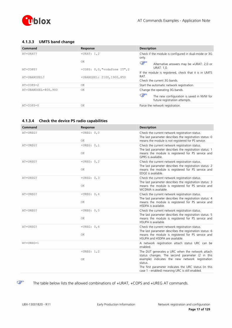
4.1.3.3 UMTS band change
Command Response Description
AT+URAT?
AT+COPS?
AT+UBANDSEL?
+URAT: 1,2
OK
+COPS: 0,0,"vodafone IT",2
+UBANDSEL: 2100,1900,850
Check if the module is configured in dual-mode or 3G only.
Alternative answers may be +URAT: 2,0 or URAT: 1,0.
If the module is registered, check that it is in UMTS
RAT.
Check the current 3G bands.
AT+COPS=2 OK Start the automatic network registration.
AT+UBANDSEL=800,900 OK Change the operating 3G bands.
The new configuration is saved in NVM for
future registration attempts.
AT+COPS=0 OK Force the network registration.
4.1.3.4 Check the device PS radio capabilities
Command Response Description
AT+UREG? +UREG: 0,0
OK
Check the current network registration status.
The last parameter describes the registration status: 0 means the module is not registered for PS service.
AT+UREG? +UREG: 0,1
OK
Check the current network registration status.
The last parameter describes the registration status: 1 means the module is registered for PS service and
GPRS is available.
AT+UREG? +UREG: 0,2
OK
Check the current network registration status.
The last parameter describes the registration status: 2 means the module is registered for PS service and
EDGE is available.
AT+UREG? +UREG: 0,3
OK
Check the current network registration status.
The last parameter describes the registration status: 3
means the module is registered for PS service and WCDMA is available.
AT+UREG? +UREG: 0,4
OK
Check the current network registration status.
The last parameter describes the registration status: 4
means the module is registered for PS service and HSDPA is available.
AT+UREG? +UREG: 0,5
OK
Check the current network registration status.
The last parameter describes the registration status: 5
means the module is registered for PS service and HSUPA is available.
AT+UREG? +UREG: 0,6
OK
Check the current network registration status.
The last parameter describes the registration status: 6 means the module is registered for PS service and
HSUPA and HSDPA are available.
AT+UREG=1 A network registration attach status URC can be enabled.
+UREG: 1,2
OK
The DUT generates a URC when the network attach status changes. The second parameter (2 in this example) indicates the new network registration
status.
The first parameter indicates the URC status (in this case 1 - enabled) meaning URC is still enabled.
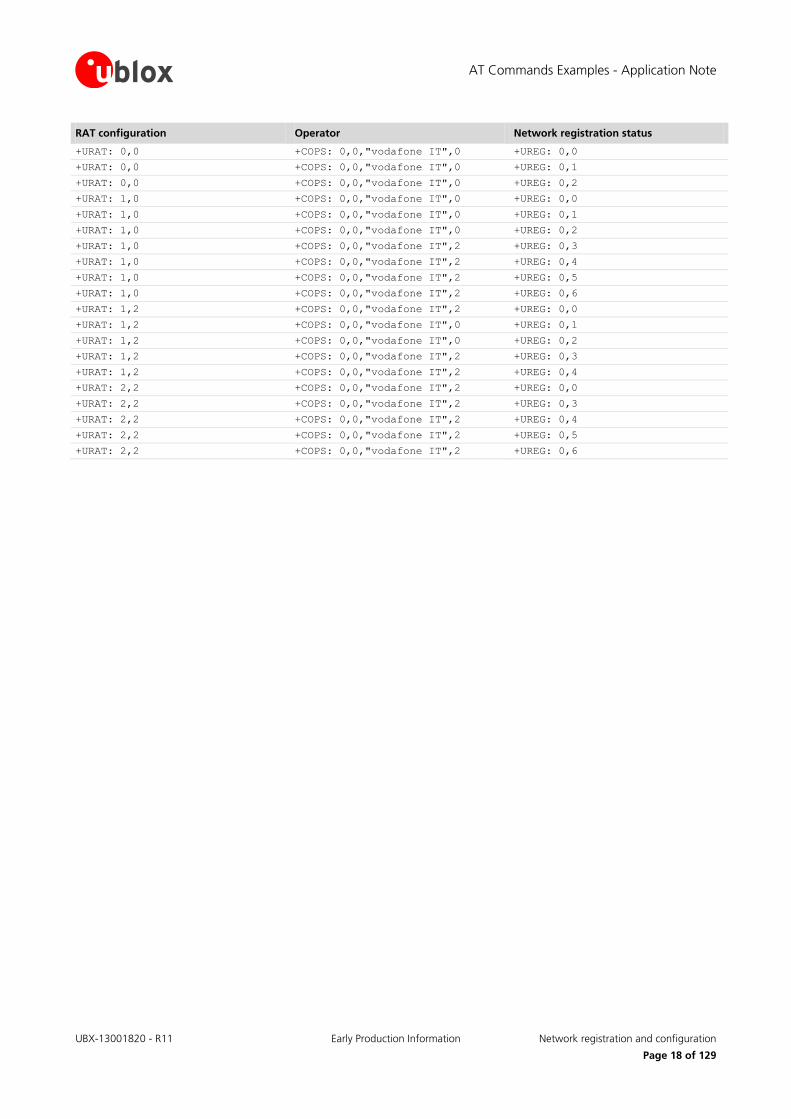
The table below lists the allowed combinations of +URAT, +COPS and +UREG AT commands.
AT Commands Examples - Application Note
UBX-13001820 - R11 Early Production Information Network registration and configuration
Page 18 of 129
RAT configuration Operator Network registration status
+URAT: 0,0 +COPS: 0,0,"vodafone IT",0 +UREG: 0,0
+URAT: 0,0 +COPS: 0,0,"vodafone IT",0 +UREG: 0,1
+URAT: 0,0 +COPS: 0,0,"vodafone IT",0 +UREG: 0,2
+URAT: 1,0 +COPS: 0,0,"vodafone IT",0 +UREG: 0,0
+URAT: 1,0 +COPS: 0,0,"vodafone IT",0 +UREG: 0,1
+URAT: 1,0 +COPS: 0,0,"vodafone IT",0 +UREG: 0,2
+URAT: 1,0 +COPS: 0,0,"vodafone IT",2 +UREG: 0,3
+URAT: 1,0 +COPS: 0,0,"vodafone IT",2 +UREG: 0,4
+URAT: 1,0 +COPS: 0,0,"vodafone IT",2 +UREG: 0,5
+URAT: 1,0 +COPS: 0,0,"vodafone IT",2 +UREG: 0,6
+URAT: 1,2 +COPS: 0,0,"vodafone IT",2 +UREG: 0,0
+URAT: 1,2 +COPS: 0,0,"vodafone IT",0 +UREG: 0,1
+URAT: 1,2 +COPS: 0,0,"vodafone IT",0 +UREG: 0,2
+URAT: 1,2 +COPS: 0,0,"vodafone IT",2 +UREG: 0,3
+URAT: 1,2 +COPS: 0,0,"vodafone IT",2 +UREG: 0,4
+URAT: 2,2 +COPS: 0,0,"vodafone IT",2 +UREG: 0,0
+URAT: 2,2 +COPS: 0,0,"vodafone IT",2 +UREG: 0,3
+URAT: 2,2 +COPS: 0,0,"vodafone IT",2 +UREG: 0,4
+URAT: 2,2 +COPS: 0,0,"vodafone IT",2 +UREG: 0,5
+URAT: 2,2 +COPS: 0,0,"vodafone IT",2 +UREG: 0,6

AT Commands Examples - Application Note
UBX-13001820 - R11 Early Production Information Network registration and configuration
Page 19 of 129
4.1.4 Network registration: LTE module
4.1.4.1 Preliminary information about Radio Access Technology (RAT) configuration
The default RAT configuration is tri-mode: GSM / UMTS / LTE, with LTE the preferred access technology.
Command Response Description
AT+URAT? +URAT: 4,3
OK
The default RAT configuration is GSM / UMTS / LTE tri-mode Radio Access technology with LTE as preferred access technology. The module can access
both GSM, UMTS and LTE networks, where LTE is the preferred RAT.
Deregister the module from the network with the AT+CFUN=4 command before changing the RAT configuration.
Issue this command sequence to ensure the preferred RAT is selected after the network de-registration / registration:
o AT+CFUN=4
o AT+URAT=<SelectedAcT>,<PreferredAcT>
o AT+CFUN=1
Power off the module (AT+CPWROFF) to store the RAT configuration in the NVM. After this, switch on the module and repeat the steps listed in section 4.1.1.
When a new RAT setting is saved in the NVM it is not possible to load the RAT factory-programmed configuration. To restore this, perform the following steps:
Command Response Description
AT+CFUN=4 OK Deregister the module from the network. Perform this operation only if the module is registered with the
network.
AT+URAT=4,3 OK Select GSM / UMTS / LTE tri-mode RAT with LTE
networks preferred.
This is the RAT factory-programmed configuration.
AT+CPWROFF OK Switch off the module.
4.1.4.2 RAT selection
LTE single mode RAT
Command Response Description
AT+CFUN=4 OK Set the module in airplane mode.
AT+URAT=3 OK Select LTE Single Mode RAT.
AT+URAT? +URAT: 3
OK
The module can access only LTE networks.
AT+CFUN=1 OK Set the module in full functionality.
AT+COPS? +COPS: 0,0,"vodafone IT",7
OK
Check the network registration status.
The last parameter describes which type of RAT (2G,
3G or 4G) the module is currently registered to (7 – LTE in this case).
TOBY-L2
AT Commands Examples - Application Note
UBX-13001820 - R11 Early Production Information Network registration and configuration
Page 20 of 129
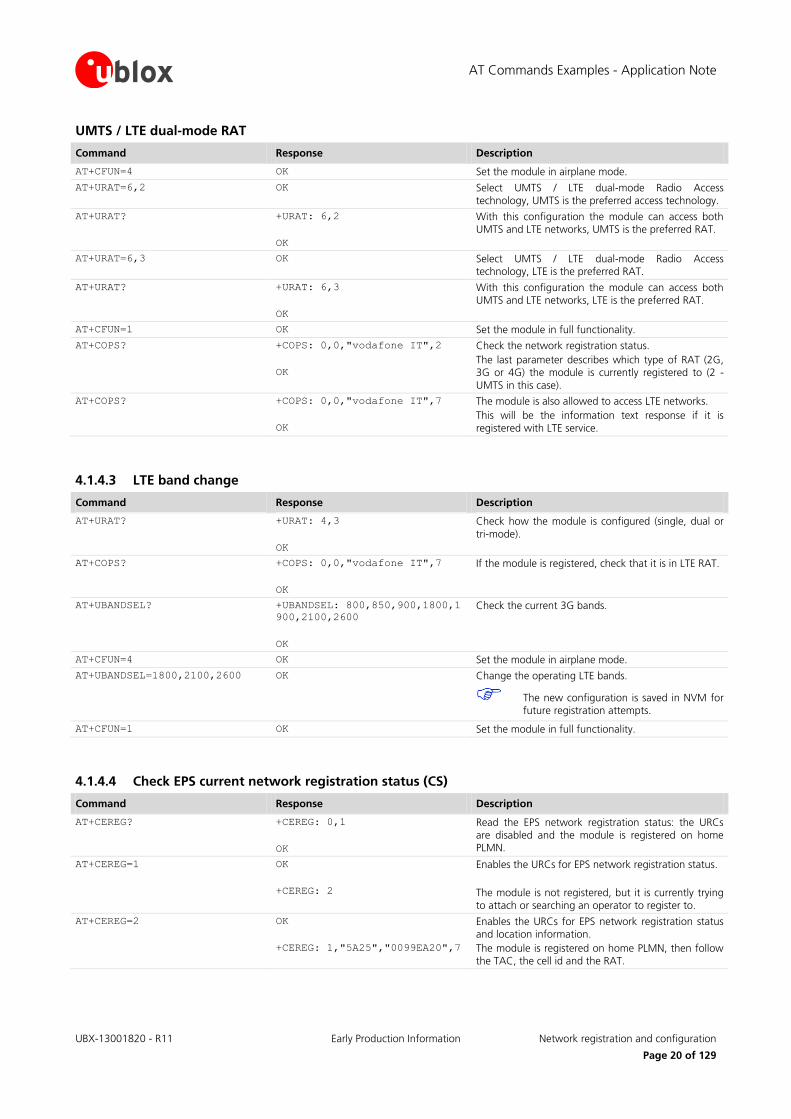
UMTS / LTE dual-mode RAT
Command Response Description
AT+CFUN=4 OK Set the module in airplane mode.
AT+URAT=6,2 OK Select UMTS / LTE dual-mode Radio Access
technology, UMTS is the preferred access technology.
AT+URAT? +URAT: 6,2
OK
With this configuration the module can access both UMTS and LTE networks, UMTS is the preferred RAT.
AT+URAT=6,3 OK Select UMTS / LTE dual-mode Radio Access technology, LTE is the preferred RAT.
AT+URAT? +URAT: 6,3
OK
With this configuration the module can access both UMTS and LTE networks, LTE is the preferred RAT.
AT+CFUN=1 OK Set the module in full functionality.
AT+COPS? +COPS: 0,0,"vodafone IT",2
OK
Check the network registration status.
The last parameter describes which type of RAT (2G, 3G or 4G) the module is currently registered to (2 -
UMTS in this case).
AT+COPS? +COPS: 0,0,"vodafone IT",7
OK
The module is also allowed to access LTE networks.
This will be the information text response if it is
registered with LTE service.
4.1.4.3 LTE band change
Command Response Description
AT+URAT?
+URAT: 4,3
OK
Check how the module is configured (single, dual or
tri-mode).
AT+COPS? +COPS: 0,0,"vodafone IT",7
OK
If the module is registered, check that it is in LTE RAT.
AT+UBANDSEL? +UBANDSEL: 800,850,900,1800,1
900,2100,2600
OK
Check the current 3G bands.
AT+CFUN=4 OK Set the module in airplane mode.
AT+UBANDSEL=1800,2100,2600 OK Change the operating LTE bands.
The new configuration is saved in NVM for future registration attempts.
AT+CFUN=1 OK Set the module in full functionality.
4.1.4.4 Check EPS current network registration status (CS)
Command Response Description
AT+CEREG? +CEREG: 0,1
OK
Read the EPS network registration status: the URCs are disabled and the module is registered on home PLMN.
AT+CEREG=1 OK
+CEREG: 2
Enables the URCs for EPS network registration status.
The module is not registered, but it is currently trying to attach or searching an operator to register to.
AT+CEREG=2 OK
+CEREG: 1,"5A25","0099EA20",7
Enables the URCs for EPS network registration status and location information.
The module is registered on home PLMN, then follow the TAC, the cell id and the RAT.
AT Commands Examples - Application Note
UBX-13001820 - R11 Early Production Information Network registration and configuration
Page 21 of 129
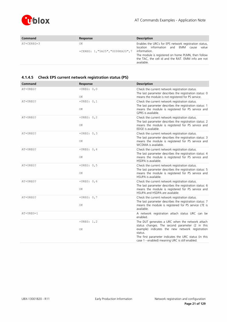
Command Response Description
AT+CEREG=3 OK
+CEREG: 1,"5A25","0099EA20",7
Enables the URCs for EPS network registration status, location information and EMM cause value
information.
The module is registered on home PLMN, then follow the TAC, the cell id and the RAT. EMM info are not
available.
4.1.4.5 Check EPS current network registration status (PS)
Command Response Description
AT+UREG? +UREG: 0,0
OK
Check the current network registration status.
The last parameter describes the registration status: 0
means the module is not registered for PS service.
AT+UREG? +UREG: 0,1
OK
Check the current network registration status.
The last parameter describes the registration status: 1
means the module is registered for PS service and GPRS is available.
AT+UREG? +UREG: 0,2
OK
Check the current network registration status.
The last parameter describes the registration status: 2
means the module is registered for PS service and EDGE is available.
AT+UREG? +UREG: 0,3
OK
Check the current network registration status.
The last parameter describes the registration status: 3 means the module is registered for PS service and WCDMA is available.
AT+UREG? +UREG: 0,4
OK
Check the current network registration status.
The last parameter describes the registration status: 4 means the module is registered for PS service and
HSDPA is available.
AT+UREG? +UREG: 0,5
OK
Check the current network registration status.
The last parameter describes the registration status: 5 means the module is registered for PS service and
HSUPA is available.
AT+UREG? +UREG: 0,6
OK
Check the current network registration status.
The last parameter describes the registration status: 6
means the module is registered for PS service and HSUPA and HSDPA are available.
AT+UREG? +UREG: 0,7
OK
Check the current network registration status.
The last parameter describes the registration status: 7
means the module is registered for PS service LTE is available.
AT+UREG=1 A network registration attach status URC can be enabled.
+UREG: 1,2
OK
The DUT generates a URC when the network attach
status changes. The second parameter (2 in this example) indicates the new network registration status.
The first parameter indicates the URC status (in this case 1 - enabled) meaning URC is still enabled.
AT Commands Examples - Application Note
UBX-13001820 - R11 Early Production Information Network registration and configuration
Page 22 of 129
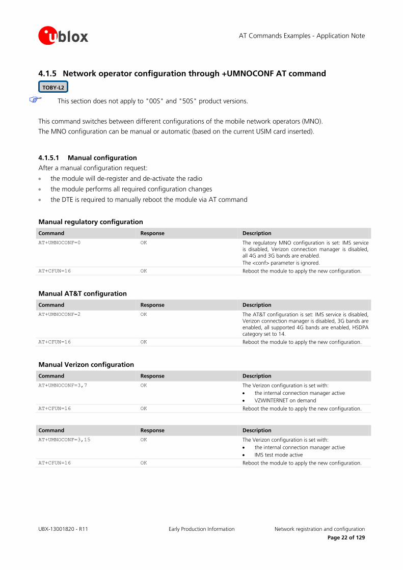
4.1.5 Network operator configuration through +UMNOCONF AT command
This section does not apply to "00S" and "50S" product versions.
This command switches between different configurations of the mobile network operators (MNO).
The MNO configuration can be manual or automatic (based on the current USIM card inserted).
4.1.5.1 Manual configuration
After a manual configuration request:
the module will de-register and de-activate the radio
the module performs all required configuration changes
the DTE is required to manually reboot the module via AT command
Manual regulatory configuration
Command Response Description
AT+UMNOCONF=0 OK The regulatory MNO configuration is set: IMS service is disabled, Verizon connection manager is disabled, all 4G and 3G bands are enabled.
The <conf> parameter is ignored.
AT+CFUN=16 OK Reboot the module to apply the new configuration.
Manual AT&T configuration
Command Response Description
AT+UMNOCONF=2 OK The AT&T configuration is set: IMS service is disabled, Verizon connection manager is disabled, 3G bands are enabled, all supported 4G bands are enabled, HSDPA
category set to 14.
AT+CFUN=16 OK Reboot the module to apply the new configuration.
Manual Verizon configuration
Command Response Description
AT+UMNOCONF=3,7 OK The Verizon configuration is set with:
the internal connection manager active
VZWINTERNET on demand
AT+CFUN=16 OK Reboot the module to apply the new configuration.
Command Response Description
AT+UMNOCONF=3,15 OK The Verizon configuration is set with:
the internal connection manager active
IMS test mode active
AT+CFUN=16 OK Reboot the module to apply the new configuration.
TOBY-L2
AT Commands Examples - Application Note
UBX-13001820 - R11 Early Production Information Network registration and configuration
Page 23 of 129
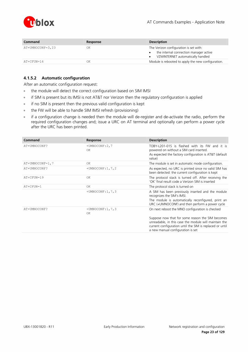
Command Response Description
AT+UMNOCONF=3,23 OK The Verizon configuration is set with:
the internal connection manager active
VZWINTERNET automatically handled
AT+CFUN=16 OK Module is rebooted to apply the new configuration.
4.1.5.2 Automatic configuration
After an automatic configuration request:
the module will detect the correct configuration based on SIM IMSI
if SIM is present but its IMSI is not AT&T nor Verizon then the regulatory configuration is applied
if no SIM is present then the previous valid configuration is kept
the FW will be able to handle SIM IMSI refresh (provisioning)
if a configuration change is needed then the module will de-register and de-activate the radio, perform the required configuration changes and; issue a URC on AT terminal and optionally can perform a power cycle after the URC has been printed.
Command Response Description
AT+UMNOCONF? +UMNOCONF:2,7
OK
TOBY-L201-01S is flashed with its FW and it is powered on without a SIM card inserted.
As expected the factory configuration is AT&T (default value)
AT+UMNOCONF=1,7 OK The module is set in automatic mode configuration.
AT+UMNOCONF? +UMNOCONF:1,7,2 As expected, no URC is printed since no valid SIM has been detected: the current configuration is kept
AT+CFUN=19 OK The protocol stack is turned off. After receiving the ‘OK’ final result code a Verizon SIM is inserted
AT+CFUN=1 OK The protocol stack is turned on
+UMNOCONF:1,7,3 A SIM has been previously inserted and the module recognizes the SIM’s IMSI.
The module is automatically reconfigured, print an URC (+UMNOCONF) and then perform a power cycle
AT+UMNOCONF? +UMNOCONF:1,7,3
OK
On next reboot the MNO configuration is checked
Suppose now that for some reason the SIM becomes
unreadable, in this case the module will maintain the current configuration until the SIM is replaced or until
a new manual configuration is set

AT Commands Examples - Application Note
UBX-13001820 - R11 Early Production Information Network registration and configuration
Page 24 of 129
4.1.6 PLMN list extension +UMNOPLMN: LTE module
This section does not apply to "00S" and "50S" product versions.
This command customizes the list used by AT+UMNOCONF’s automatic SIM detection algorithm. It configures the mapping of the current detected MNO to one of the pre-defined MNO values. It is possible to extend the PLMN list of these MNOs:
AT&T
Verizon
Command Response Description
AT+UMNOPLMN? +UMNOPLMN: 2,"310.30,310.150,
310.170,310.280,310.380,310.4
10,310.560"
+UMNOPLMN: 3,"310.590,310.890
,311.480"
OK
The module is flashed with its FW and it is powered on.
This is the factory configuration.
AT+UMNOPLMN=3,"310.150" +CME ERROR: operation not
allowed
"310.150" overlaps the current setting of <detectable_MNO>=2.
AT+UMNOPLMN=3,"1000.100" +CME ERROR: operation not
supported
"1000.100" is not a valid PLMN id
AT+UMNOPLMN=2 OK <detectable_MNO>=2 has been reset to its factory default value
TOBY-L2

AT Commands Examples - Application Note
UBX-13001820 - R11 Early Production Information Network registration and configuration
Page 25 of 129
4.2 Network registration flow-chart
Figure 3 shows the suggested operations and actions for a CS and PS registration from the DTE point of view. See the u-blox AT Commands Manual [1] for more detailed information about +CREG and +CGREG.
Module power on
AT+CREG=1
AT+COPS?
Is COPS≠2
NOYES
AT+COPS=0
or
AT+COPS=1,…..
Wait for URC
+CREG
Read +CREG
Is +CREG=0DTE is requested to
intervene
YES
(1) Everytime a URC +CREG is received, DTE shall take a decision
Is +CREG=1OK, module is registered
for CS on the HPLMN
YES
NO
Is +CREG=2Wait, module is
searching for a network
YES
Is +CREG=3
Registration denied.
DTE intervention may be
required
YES
NO
Is +CREG=4 WaitYES
Is +CREG=5OK, module is registered
for CS on a VPLMN
YES
NO
(1)
NO
NO
Figure 3: CS and PS network registration flow chart
The suggestion is to enable +CREG and +CGREG URCs after the module power-on. In this way the DTE by monitoring these URCs is always aware of the network status registration for the CS and PS subsystem. The actions to be taken by DTE are similar for both +CREG and +CGREG, but the causes may be different.
When the indication +C(G)REG=5 is received, the DTE shall use +CGED to verify if the network is an Equivalent PLMN or not, and so it can determine its roaming status.
AT Commands Examples - Application Note
UBX-13001820 - R11 Early Production Information Network registration and configuration
Page 26 of 129
SARA-U2 and LISA-U2 series support the Equivalent Home PLMN feature (its activation depends on the USIM application; see the 3GPP TS 31.102 [10]). Thus the +C(G)REG=1 URC returned to DTE, may indicate that the module is not registered on the HPLMN but on a EHPLMN.
The following is an overview of the values assumed by the <stat> parameter in +CREG:
0: a technical problem may have occurred; the user is requested to intervene. It is still possible to make emergency calls if some network is available. Possible causes:
o PIN not entered
o SIM read error
o SIM card not present
The registration is not started (+COPS=2)
1: the MT is registered on a HPLMN or an EHPLMN
2: the module is searching for a network to register on. Possible causes:
o No network available
o Available networks have insufficient Rx level
o HPLMN or allowed PLMN are available but the registration is rejected, e.g. roaming is not allowed in this Location Area
It is still possible to make emergency calls if network coverage is available.
3: the registration fails after a Location Update Reject; possible causes are:
o Illegal MS
o Illegal ME
o IMSI unknown at HLR
o PLMN not allowed
o Location area not allowed
o Roaming not allowed in this location area
o Network failure
o Network congestion
It is still possible to make emergency calls if network coverage is available.
If the registration type is manual, then no further attempt is made to search for a new PLMN or register with it. If the registration type is automatic, the MS may look for an allowed PLMN if the rejection cause was roaming restriction. In case of illegal MS / ME, there could be possible problems with either the SIM card or with the MT’s identity (IMEI): user intervention may be required.
4: this value, usually transitory, is returned if the registration state does not belong to any of the following:
o Normal o Limited o No service o Service detached o Service disabled
A failed registration procedure can be seen before starting a PLMN search, when <stat>=2.
5: the MT is registered on a VPLMN (in national/international roaming, or on an EPLMN)
The following are the recommended actions for +CGREG indications:
<stat>=0: not registered, the MT is not currently searching a new operator to register to
ACTION: send AT+COPS=0 to register, and once the module is registered (+CREG: 1), send AT+CGACT=1 to activate a new PDP context
<stat>=1: registered, home network

AT Commands Examples - Application Note
UBX-13001820 - R11 Early Production Information Network registration and configuration
Page 27 of 129
ACTION: none required, but can verify if the PDP context has been deactivated with AT+CGACT?, and if so send AT+CGACT=0 and then AT+CGACT=1 to ensure that a new PDP context is activated
<stat>=2: not registered, but the MT is currently searching a new operator to register to
ACTION: wait for +CREG: 1, no other action required, this is the case when the module has lost network coverage
<stat>=3 and <stat>=4: the registration is denied or unknown, it is not possible to activate a PDP context
ACTION: this may occur due to the module being unable to find signals for desired carrier, moving the device to another location may help, otherwise suggest recalling device for repair
<stat>=5: registered, roaming
ACTION: verify if the PDP context has been deactivated with AT+CGACT?, and if so send AT+CGACT=0 and then AT+CGACT=1 to ensure that a new PDP context is activated
Another URC which is useful for monitoring the PS status is +CGEV which can be configured via +CGEREP, for more information see the u-blox AT commands manual [1]. The URC +CGEV returns information about the GPRS mobile class, the PDP context status and the GPRS attach status.

AT Commands Examples - Application Note
UBX-13001820 - R11 Early Production Information GPRS connection
Page 28 of 129
5 GPRS connection
5.1 External PDP context handling
This section explains how to define, activate and deactivate an external Packet Data Protocol (PDP) context, i.e. a data connection using the external IP stack (e.g. Windows dial up) and PPP over the communication port (UART/USB).
5.1.1 External PDP context definition and activation
An external PDP context can be defined with +CGDCONT and then activated with +CGACT, +CGDATA="PPP",
<cid> or ATD*99***<cid># (dial up).
The maximum number of definable PDP contexts is 3.
The +CGQREQ and +CGEQREQ (for the 3G network) commands configure the parameter <cid> that identifies the Quality of Service (QoS) profile for the PDP context. A QoS profile can be specified after the PDP context definition it is associated to and before its activation.
A minimum acceptable QoS profile for a PDP context may be specified with +CGQMIN and +CGEQMIN. However, the usage of these commands should be restricted to the cases where minimum QoS parameters are specifically constrained by the external application.
Command Response Description
AT+CGDCONT=1,"IP","web.omnitel
.it"
OK Define the PDP context 1 with PDP type "IP" and APN "web.omnitel.it".
AT+CGDCONT=3,"IP","internet" OK Define the PDP context 3 with PDP type "IP" and APN "internet".
AT+CGDCONT=2,"IP","mms.vodafon
e.it"
OK Define the PDP context 2 with PDP type "IP" and APN "mms.vodafone.it".
AT+CGDCONT? +CGDCONT: 1,"IP","web.omnitel
.it","0.0.0.0",0,0
+CGDCONT: 3,"IP","internet","
0.0.0.0",0,0
+CGDCONT: 2,"IP","mms.vodafon
e.it","0.0.0.0",0,0
OK
Read the PDP contexts’ parameters.
AT+CGEQREQ=1,3,64,64,,,0,320,"
1E4","1E5",1,,3
OK Define a QoS profile for PDP context 1, with Traffic
Class 3 (background), maximum bit rate 64 kb/s both for UL and for DL, no Delivery Order requirements, a maximum SDU size of 320 octets, an SDU error ratio
of 10-4, a residual bit error ratio of 10
-5, delivery of
erroneous SDUs allowed and Traffic Handling Priority
3.
AT+CGQREQ=2,1,3,4,5,6 OK Define a QoS profile for PDP context 2, with Precedence Class 1, Delay Class 3, Reliability Class 4, Peak Throughput Class 5 and Mean Throughput Class
6.
AT+CGACT=1,1 OK PDP context 1 activation (alternatively with AT+CGDATA="PPP", 1 or ATD*99***1#).
AT+CGPADDR=1 +CGPADDR: 1,"91.80.104.82"
OK
Show address of PDP context 1. If PPP is used this command shall be sent from another AT command interface.
SARA-U LISA-U

AT Commands Examples - Application Note
UBX-13001820 - R11 Early Production Information GPRS connection
Page 29 of 129
Command Response Description
AT+CGDCONT? +CGDCONT: 1,"IP","web.omnitel
.it","91.80.104.82",0,0
+CGDCONT: 3,"IP","internet","
0.0.0.0",0,0
+CGDCONT: 2,"IP","mms.vodafon
e.it","0.0.0.0",0,0
OK
Read the PDP contexts’ parameters.
AT+CGEQNEG=1 +CGEQNEG: 1,3,64,64,0,0,0,320
,"1E4","1E5",1,1000,3,0,0
OK
Read the negotiated QoS profile for the PDP context 1.
AT+CGACT=0,1 OK PDP context 1 deactivation.
AT+CGDCONT? +CGDCONT: 1,"IP","web.omnitel
.it","0.0.0.0",0,0
+CGDCONT: 3,"IP","internet","
0.0.0.0",0,0
+CGDCONT: 2,"IP","mms.vodafon
e.it","0.0.0.0",0,0
OK
Read the PDP contexts’ parameters.
AT+CGACT=1 OK All defined PDP contexts activation.
AT+CGDCONT? +CGDCONT: 1,"IP","web.omnitel
.it","91.80.101.207",0,0
+CGDCONT: 3,"IP","internet","
83.225.114.136",0,0
+CGDCONT: 2,"IP","mms.vodafon
e.it","10.159.135.60",0,0
OK
Read the PDP contexts’ parameters: all PDP contexts have different PDP addresses.
AT+CGEQNEG=2 +CGEQNEG: 2,2,128,128,0,0,0,1
500,"1E3","1E5",0,1000,3,0,0
OK
Read the negotiated QoS profile for the PDP context 2.
AT+CGACT=0 OK All defined PDP contexts deactivation.
AT+CGDCONT? +CGDCONT: 1,"IP","web.omnitel
.it","0.0.0.0",0,0
+CGDCONT: 3,"IP","internet","
0.0.0.0",0,0
+CGDCONT: 2,"IP","mms.vodafon
e.it","0.0.0.0",0,0
OK
Read the PDP contexts’ parameters.
AT+CGACT=1,2 OK PDP context 2 activation.
AT+CGDCONT? +CGDCONT: 1,"IP","web.omnitel
.it","0.0.0.0",0,0
+CGDCONT: 3,"IP","internet","
0.0.0.0",0,0
+CGDCONT: 2,"IP","mms.vodafon
e.it","10.153.123.229",0,0
OK
Read the PDP contexts’ parameters.
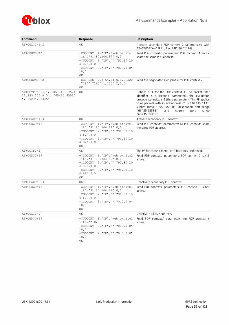
5.1.1.1 Secondary PDP context definition and activation
A secondary PDP context is an external PDP context associated with a primary external PDP context and sharing the same PDP address and APN with it. The primary and the associated secondary PDP contexts are typically used to provide connection to the same PDN (Packet Data Network) with different guaranteed QoS.
The typical usage of the secondary PDP contexts is in VoIP calls, where RTP (speech) packets are conveyed on one PDP context (e.g. the primary one) with a given QoS (e.g. low reliability) whereas SIP signaling is routed on a different PDP context (e.g. the secondary one, with the same IP address but different port numbers) with a more reliable QoS.
The +CGDSCONT AT command defines the secondary PDP contexts. Since the maximum number of definable PDP contexts is three, the maximum number of definable secondary PDP contexts is two.
The primary PDP context must be activated before activating an associated secondary PDP context.

AT Commands Examples - Application Note
UBX-13001820 - R11 Early Production Information GPRS connection
Page 30 of 129
In addition, before a secondary PDP context activation, at least one Packet Filter (PF) for a Traffic Flow Template (TFT) must be defined with +CGTFT.
The TFT is stored by the GGSN and it is examined when routing downlink user plane data. A TFT incorporates from one to eight PF, each characterized by a Packet Filter Identifier (PFI) and an Evaluation Precedence Index (EPI). The EPI specifies the precedence class among all PFs associated with a PDP address. Any incoming packet is first checked against the PF with lowest EPI and, in case no match is found, it is matched against the PF with the next highest EPI.
A valid packet filter must contain a unique identifier (within all PFs for a given TFT) and a unique evaluation precedence index (within all TFTs for one PDP address). If a PF is defined, with a PFI which already identifies another PF for the same TFT, the second PF overwrites the first, so that all PFIs are unique within a TFT.
In addition, at least one of the following parameters must be included for a TFT definition:
<source_address_and_subnet_mask>
<protocol_number_(ipv4)-next_header_(ipv6)>
<destination_port_range>
<source_port_range>
<ipsec_security_parameter_index_(spi)>
<type_of_service_(tos)_(ipv4)_and_mask-traffic_class_(ipv6)_and_mask>
<flow_label (ipv6)>
The allowed combinations are:
Combination 1:
o <source_address_and_subnet_mask> o <protocol_number_(ipv4)-next_header_(ipv6)> o <destination_port_range> o <source_port_range> o <type_of_service_(tos)_(ipv4)_and_mask-traffic_class_(ipv6)_and_mask>
Combination 2:
o <source_address_and_subnet_mask> o <protocol_number_(ipv4)-next_header_(ipv6)> o <ipsec_security_parameter_index_(spi)> o <type_of_service_(tos)_(ipv4)_and_mask-traffic_class_(ipv6)_and_mask>
Combination 3:
o <source_address_and_subnet_mask> o <type_of_service_(tos)_(ipv4)_and_mask-traffic_class_(ipv6)_and_mask> o <flow_label (ipv6)>
The secondary PDP contexts can be defined and activated as follows:
Command Response Description
AT+CGDCONT=1,"IP","web.omnite
l.it"
OK Define the primary PDP context 1.
AT+CGEQREQ=1,4,32,32,,,0,320,
"1E4","1E5",1,,1
OK Define a QoS profile for PDP context 1, with Traffic Class 4 (subscribed value), maximum bit rate 32 kb/s
both for UL and for DL, no Delivery Order requirements, a maximum SDU size of 320 octets, an
SDU error ratio of 10-4, a residual bit error ratio of 10
-5,
delivery of erroneous SDUs allowed and Traffic
Handling Priority 1.

AT Commands Examples - Application Note
UBX-13001820 - R11 Early Production Information GPRS connection
Page 31 of 129
Command Response Description
AT+CGDSCONT=2,1 OK Define a secondary PDP context with context identifier 2 associated to the primary PDP context with context
identifier 1.
AT+CGEQREQ=2,3,64,64,,,0,320,
"1E4","1E5",1,,2
Define a QoS profile for secondary PDP context 2, with
Traffic Class 3 (background), maximum bit rate 64 kb/s both for UL and for DL, no Delivery Order requirements, a maximum SDU size of 320 octets, an
SDU error ratio of 10-4, a residual bit error ratio of 10
-5,
delivery of erroneous SDUs allowed and Traffic
Handling Priority 2.
AT+CGDSCONT=3,1 OK Define a secondary PDP context with context identifier 3 associated to the primary PDP context with context identifier 1.
AT+CGEQREQ=3,2,64,64,,,0,320,
"1E4","1E5",1,,3,,0
OK Define a QoS profile for secondary PDP context 3, with Traffic Class 2 (Interactive), maximum bit rate 64 kb/s
both for UL and for DL, no Delivery Order requirements, a maximum SDU size of 320 octets, an
SDU error ratio of 10-4, a residual bit error ratio of 10
-5,
delivery of erroneous SDUs allowed, and Traffic
Handling Priority 3.
Since the Traffic Class is set to "Interactive" the last parameter, "Signaling Indicator", has to be specified
too: in this case it is set to 0 (PDP context is not optimized for signaling).
AT+CGDCONT? +CGDCONT: 1,"IP","web.omnitel
.it","0.0.0.0",0,0
+CGDCONT: 2,"IP","","0.0.0.0"
,0,0
+CGDCONT: 3,"IP","","0.0.0.0"
,0,0
OK
Read PDP contexts’ parameters.
AT+CGACT=1,2 +CME ERROR: operation not
allowed
The secondary PDP context 2 cannot be activated before the primary PDP context 1 activation and before
a Traffic Flow Template definition for PDP context 2 (with +CGTFT command).
AT+CGACT=1,1 OK Primary PDP context 1 activation (alternatively with AT+CGDATA="PPP", 1 or ATD*99***1#).
AT+CGDCONT? +CGDCONT: 1,"IP","web.omnitel
.it","91.80.104.82",0,0
+CGDCONT: 2,"IP","","0.0.0.0"
,0,0
+CGDCONT: 3,"IP","","0.0.0.0"
,0,0
OK
Read PDP contexts’ parameters. If PPP is used this command shall be sent from another AT command
interface.
AT+CGEQNEG=1 +CGEQNEG: 1,2,32,32,0,0,0,320
,"1E4","1E5",1,1000,1,0,0
OK
Read the negotiated QoS profile for PDP context 1.
AT+CGTFT=2,1,1,"109.115.145.1
13.255.255.0.0"
OK Define a PF for PDP context 2. The packet filter identifier is 1 (second parameter), the evaluation
precedence index is 1 (third parameter).
This PF applies to all packets with source address "109.115.145.113" and subnet mask "255.255.0.0".
AT+CGTFT=2,2,3,"91.80.105.10.
255.255.0.0",,"65435.65535","
65235.65335"
OK Defines another PF for PDP context 2. The packet filter identifier is 2 (second parameter), the evaluation
precedence index is 3 (third parameter). This PF applies to all packets with source address "91.80.105.10",
subnet mask "255.255.0.0", destination port range "65435.65535" and source port range
"65235.65335".
AT+CGTFT=2,3,2,"71.40.10.10.2
55.255.0.0"
OK Defines another PF for PDP context 2. The packet filter identifier is 3; the evaluation precedence index is 2.
This PF applies to all packets with source address "71.40.10.10" and subnet mask "255.255.0.0".
AT Commands Examples - Application Note
UBX-13001820 - R11 Early Production Information GPRS connection
Page 32 of 129
Command Response Description
AT+CGACT=1,2 OK Activate secondary PDP context 2 (alternatively with AT+CGDATA="PPP", 2 or ATD*99***2#).
AT+CGDCONT? +CGDCONT: 1,"IP","web.omnitel
.it","91.80.104.82",0,0
+CGDCONT: 2,"IP","","91.80.10
4.82",0,0
+CGDCONT: 3,"IP","","0.0.0.0"
,0,0
OK
Read PDP contexts’ parameters: PDP contexts 1 and 2 share the same PDP address.
AT+CGEQNEG=2 +CGEQNEG: 2,3,64,64,0,0,0,320
,"1E4","1E5",1,1000,2,0,0
OK
Read the negotiated QoS profile for PDP context 2.
AT+CGTFT=3,4,4,"105.110.145.1
13.255.255.0.0",,"65435.65535
","65235.65335"
OK Defines a PF for the PDP context 3. The packet filter identifier is 4 (second parameter), the evaluation
precedence index is 4 (third parameter). This PF applies to all packets with source address "105.110.145.113",
subnet mask "255.255.0.0", destination port range "65435.65535" and source port range "65235.65335".
AT+CGACT=1,3 OK Activate secondary PDP context 3.
AT+CGDCONT? +CGDCONT: 1,"IP","web.omnitel
.it","91.80.104.82",0,0
+CGDCONT: 2,"IP","","91.80.10
4.82",0,0
+CGDCONT: 3,"IP","","91.80.10
4.82",0,0
OK
Read PDP contexts’ parameters: all PDP contexts share the same PDP address.
AT+CGTFT=2 OK The PF for context identifier 2 becomes undefined.
AT+CGDCONT? +CGDCONT: 1,"IP","web.omnitel
.it","91.80.104.82",0,0
+CGDCONT: 2,"IP","","91.80.10
4.82",0,0
+CGDCONT: 3,"IP","","91.80.10
4.82",0,0
OK
Read PDP contexts’ parameters: PDP context 2 is still
active.
AT+CGACT=0,3 OK Deactivate secondary PDP context 3.
AT+CGDCONT? +CGDCONT: 1,"IP","web.omnitel
.it","91.80.104.82",0,0
+CGDCONT: 2,"IP","","91.80.10
4.82",0,0
+CGDCONT: 3,"IP","","0.0.0.0"
,0,0
OK
Read PDP contexts’ parameters: PDP context 3 is not active.
AT+CGACT=0 OK Deactivate all PDP contexts.
AT+CGDCONT? +CGDCONT: 1,"IP","web.omnitel
.it","",0,0
+CGDCONT: 3,"IP","","0.0.0.0"
,0,0
+CGDCONT: 2,"IP","","0.0.0.0"
,0,0
OK
Read PDP contexts’ parameters: no PDP context is active.
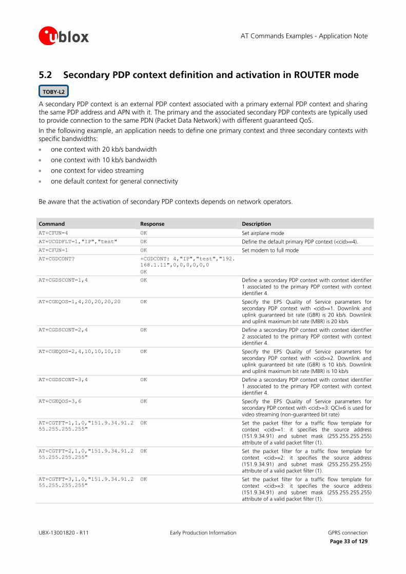
AT Commands Examples - Application Note
UBX-13001820 - R11 Early Production Information GPRS connection
Page 33 of 129
5.2 Secondary PDP context definition and activation in ROUTER mode
A secondary PDP context is an external PDP context associated with a primary external PDP context and sharing the same PDP address and APN with it. The primary and the associated secondary PDP contexts are typically used to provide connection to the same PDN (Packet Data Network) with different guaranteed QoS.
In the following example, an application needs to define one primary context and three secondary contexts with specific bandwidths:
one context with 20 kb/s bandwidth
one context with 10 kb/s bandwidth
one context for video streaming
one default context for general connectivity
Be aware that the activation of secondary PDP contexts depends on network operators.
Command Response Description
AT+CFUN=4 OK Set airplane mode
AT+UCGDFLT=1,"IP","test" OK Define the default primary PDP context (<cid>=4).
AT+CFUN=1 OK Set modem to full mode
AT+CGDCONT? +CGDCONT: 4,"IP","test","192.
168.1.11",0,0,0,0,0,0
OK
AT+CGDSCONT=1,4 OK Define a secondary PDP context with context identifier 1 associated to the primary PDP context with context
identifier 4.
AT+CGEQOS=1,4,20,20,20,20 OK Specify the EPS Quality of Service parameters for secondary PDP context with <cid>=1. Downlink and uplink guaranteed bit rate (GBR) is 20 kb/s. Downlink
and uplink maximum bit rate (MBR) is 20 kb/s
AT+CGDSCONT=2,4 OK Define a secondary PDP context with context identifier
2 associated to the primary PDP context with context identifier 4.
AT+CGEQOS=2,4,10,10,10,10 OK Specify the EPS Quality of Service parameters for secondary PDP context with <cid>=2. Downlink and uplink guaranteed bit rate (GBR) is 10 kb/s. Downlink
and uplink maximum bit rate (MBR) is 10 kb/s
AT+CGDSCONT=3,4 OK Define a secondary PDP context with context identifier 1 associated to the primary PDP context with context identifier 4.
AT+CGEQOS=3,6 OK Specify the EPS Quality of Service parameters for secondary PDP context with <cid>=3: QCI=6 is used for
video streaming (non-guaranteed bit rate)
AT+CGTFT=1,1,0,"151.9.34.91.2
55.255.255.255"
OK Set the packet filter for a traffic flow template for context <cid>=1: it specifies the source address (151.9.34.91) and subnet mask (255.255.255.255)
attribute of a valid packet filter (1).
AT+CGTFT=2,1,0,"151.9.34.91.2
55.255.255.255"
OK Set the packet filter for a traffic flow template for
context <cid>=2: it specifies the source address (151.9.34.91) and subnet mask (255.255.255.255) attribute of a valid packet filter (1).
AT+CGTFT=3,1,0,"151.9.34.91.2
55.255.255.255"
OK Set the packet filter for a traffic flow template for context <cid>=3: it specifies the source address
(151.9.34.91) and subnet mask (255.255.255.255) attribute of a valid packet filter (1).
TOBY-L2
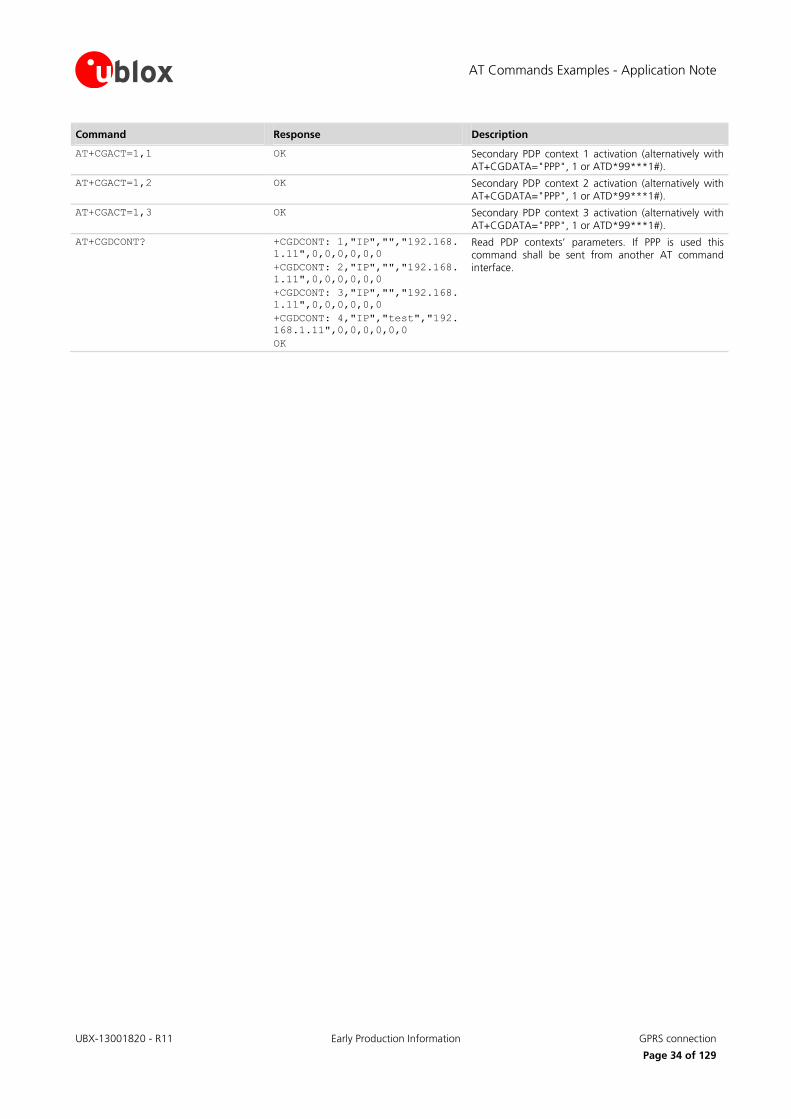
AT Commands Examples - Application Note
UBX-13001820 - R11 Early Production Information GPRS connection
Page 34 of 129
Command Response Description
AT+CGACT=1,1 OK Secondary PDP context 1 activation (alternatively with AT+CGDATA="PPP", 1 or ATD*99***1#).
AT+CGACT=1,2 OK Secondary PDP context 2 activation (alternatively with AT+CGDATA="PPP", 1 or ATD*99***1#).
AT+CGACT=1,3 OK Secondary PDP context 3 activation (alternatively with AT+CGDATA="PPP", 1 or ATD*99***1#).
AT+CGDCONT? +CGDCONT: 1,"IP","","192.168.
1.11",0,0,0,0,0,0
+CGDCONT: 2,"IP","","192.168.
1.11",0,0,0,0,0,0
+CGDCONT: 3,"IP","","192.168.
1.11",0,0,0,0,0,0
+CGDCONT: 4,"IP","test","192.
168.1.11",0,0,0,0,0,0
OK
Read PDP contexts’ parameters. If PPP is used this command shall be sent from another AT command interface.
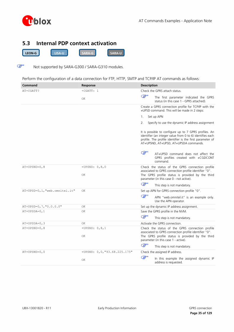
AT Commands Examples - Application Note
UBX-13001820 - R11 Early Production Information GPRS connection
Page 35 of 129
5.3 Internal PDP context activation
Not supported by SARA-G300 / SARA-G310 modules.
Perform the configuration of a data connection for FTP, HTTP, SMTP and TCP/IP AT commands as follows:
Command Response Description
AT+CGATT? +CGATT: 1
OK
Check the GPRS attach status.
The first parameter indicated the GPRS
status (in this case 1 - GPRS attached).
Create a GPRS connection profile for TCP/IP with the +UPSD command. This will be made in 2 steps:
1. Set up APN
2. Specify to use the dynamic IP address assignment
It is possible to configure up to 7 GPRS profiles. An identifier (an integer value from 0 to 6) identifies each
profile. The profile identifier is the first parameter of AT+UPSND, AT+UPSD, AT+UPSDA commands.
AT+UPSD command does not affect the GPRS profiles created with +CGDCONT command.
AT+UPSND=0,8 +UPSND: 0,8,0
OK
Check the status of the GPRS connection profile associated to GPRS connection profile identifier "0".
The GPRS profile status is provided by the third parameter (in this case 0 - not active).
This step is not mandatory.
AT+UPSD=0,1,"web.omnitel.it" OK Set up APN for GPRS connection profile "0".
APN "web.omnitel.it" is an example only. Use the APN operator.
AT+UPSD=0,7,"0.0.0.0" OK Set up the dynamic IP address assignment.
AT+UPSDA=0,1 OK Save the GPRS profile in the NVM.
This step is not mandatory.
AT+UPSDA=0,3 OK Activate the GPRS connection.
AT+UPSND=0,8 +UPSND: 0,8,1
OK
Check the status of the GPRS connection profile
associated to GPRS connection profile identifier "0".
The GPRS profile status is provided by the third parameter (in this case 1 - active).
This step is not mandatory.
AT+UPSND=0,0 +UPSND: 0,0,"93.68.225.175"
OK
Check the assigned IP address.
In this example the assigned dynamic IP address is requested.
SARA-U SARA-G LISA-U LEON-G
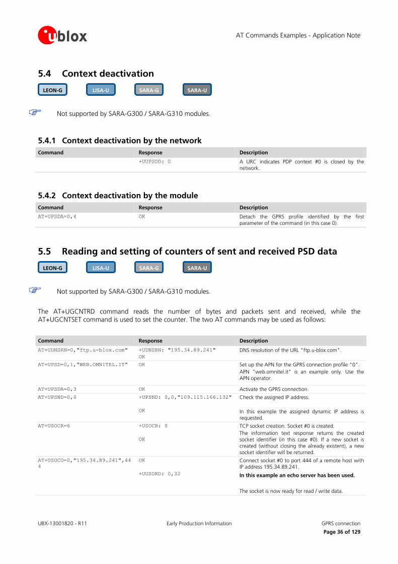
AT Commands Examples - Application Note
UBX-13001820 - R11 Early Production Information GPRS connection
Page 36 of 129
5.4 Context deactivation
Not supported by SARA-G300 / SARA-G310 modules.
5.4.1 Context deactivation by the network
Command Response Description
+UUPSDD: 0 A URC indicates PDP context #0 is closed by the network.
5.4.2 Context deactivation by the module
Command Response Description
AT+UPSDA=0,4 OK Detach the GPRS profile identified by the first parameter of the command (in this case 0).
5.5 Reading and setting of counters of sent and received PSD data
Not supported by SARA-G300 / SARA-G310 modules.
The AT+UGCNTRD command reads the number of bytes and packets sent and received, while the AT+UGCNTSET command is used to set the counter. The two AT commands may be used as follows:
Command Response Description
AT+UDNSRN=0,"ftp.u-blox.com" +UDNSRN: "195.34.89.241"
OK
DNS resolution of the URL "ftp.u-blox.com".
AT+UPSD=0,1,"WEB.OMNITEL.IT" OK Set up the APN for the GPRS connection profile "0".
APN "web.omnitel.it" is an example only. Use the
APN operator.
AT+UPSDA=0,3 OK Activate the GPRS connection.
AT+UPSND=0,0 +UPSND: 0,0,"109.115.166.132"
OK
Check the assigned IP address.
In this example the assigned dynamic IP address is
requested.
AT+USOCR=6 +USOCR: 0
OK
TCP socket creation. Socket #0 is created.
The information text response returns the created
socket identifier (in this case #0). If a new socket is created (without closing the already existent), a new socket identifier will be returned.
AT+USOCO=0,"195.34.89.241",44
4
OK
+UUSORD: 0,32
Connect socket #0 to port 444 of a remote host with IP address 195.34.89.241.
In this example an echo server has been used.
The socket is now ready for read / write data.
SARA-U SARA-G LISA-U LEON-G
SARA-U SARA-G LISA-U LEON-G

AT Commands Examples - Application Note
UBX-13001820 - R11 Early Production Information GPRS connection
Page 37 of 129
Command Response Description
AT+UGCNTRD +UGCNTRD: 4,124,116,124,116
OK
Read the counters for total sent and received bytes for the defined context.
The total number of sent bytes on UL is 124 (44
bytes of SYN plus 40 bytes of ACK for TCP three-way-handshake plus 40 bytes of ACK for the
received data)
The total number of received bytes is 116 (44 bytes of SYN-ACK for TCP three-way-handshake
plus 72 bytes of received data)
AT+USORD=0,1024 +USORD=0,32,"u-blox AG
TCP/UDP test service"
OK
Read data.
The data is returned between quotation marks.
AT+USOWR=0,10,"HELLOWORLD" +USOWR: 0,10
OK
Write 10 data bytes data on socket #0.
If the final result code is returned then the data is sent to lower level of protocol stack.
AT+UGCNTRD +UGCNTRD: 4,214,206,214,206
OK
Read the counters for total sent and received bytes for the defined context.
The total number of sent bytes on UL has
increased of 90 bytes (50 bytes of sent data plus 40 bytes of ACK for the received data)
The total number of received bytes has increased
of 90 bytes (50 bytes of received data plus 40 bytes of ACK for the sent data)
AT+UGCNTSET=4,0,0 OK Set the counter for total sent/received bytes to 0 for
the PDP context identified by <cid> 4.
AT+UGCNTRD +UGCNTRD: 4,0,0,0,0
OK
Read the counters for total sent / received bytes for the defined context.
5.6 DoCoMo PS PUSH context manual activation
Supported only by LISA-U200-62S version.
The connection will take place on the same COM port where it has been accepted.
Command Response Description
AT+CGAUTO=3 OK Set the automatic acceptance of Packet Domain network requests in modem compatibility mode, i.e.
controlled by the S0 command.
ATS0=0 OK Disable the automatic answering. AT+CRC=1 OK Enables detailed ring indication for the incoming calls.
+CRING: GPRS "PPP","","M-PPP-
RELAY","<apn_name>"
The PS PUSH has been received.
The URC shows the PDP_type, the PDP_addr the requested L2P protocol and the APN of the incoming
"Request PDP Context Activation".
If PDP_type = "PPP" then the PDP_addr will be empty and the L2P protocol required will
be the PPP relay (M-PPP-RELAY).
If PDP_type = "IP" then the PDP_addr will be shown and the P2P protocol will be empty.
LISA-U
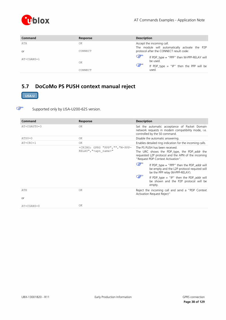
AT Commands Examples - Application Note
UBX-13001820 - R11 Early Production Information GPRS connection
Page 38 of 129
Command Response Description
ATA
or
AT+CGANS=1
OK
CONNECT
OK
CONNECT
Accept the incoming call.
The module will automatically activate the P2P protocol after the CONNECT result code:
If PDP_type = "PPP" then M-PPP-RELAY will
be used.
If PDP_type = "IP" then the PPP will be used.
5.7 DoCoMo PS PUSH context manual reject
Supported only by LISA-U200-62S version.
Command Response Description
AT+CGAUTO=3 OK Set the automatic acceptance of Packet Domain network requests in modem compatibility mode, i.e.
controlled by the S0 command.
ATS0=0 OK Disable the automatic answering.
AT+CRC=1 OK Enables detailed ring indication for the incoming calls.
+CRING: GPRS "PPP","","M-PPP-
RELAY","<apn_name>"
The PS PUSH has been received.
The URC shows the PDP_type, the PDP_addr the
requested L2P protocol and the APN of the incoming "Request PDP Context Activation".
If PDP_type = "PPP" then the PDP_addr will
be empty and the L2P protocol required will be the PPP relay (M-PPP-RELAY).
If PDP_type = "IP" then the PDP_addr will be shown and the P2P protocol will be empty.
ATH
or
AT+CGANS=0
OK
OK
Reject the incoming call and send a "PDP Context Activation Request Reject"
LISA-U
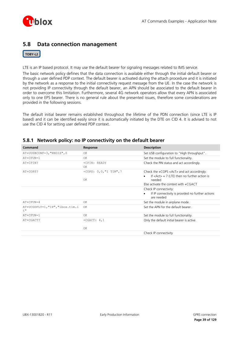
AT Commands Examples - Application Note
UBX-13001820 - R11 Early Production Information GPRS connection
Page 39 of 129
5.8 Data connection management
LTE is an IP based protocol. It may use the default bearer for signaling messages related to IMS service.
The basic network policy defines that the data connection is available either through the initial default bearer or through a user defined PDP context. The default bearer is activated during the attach procedure and it is initiated by the network as a response to the initial connectivity request message from the UE. In the case the network is not providing IP connectivity through the default bearer, an APN should be associated to the default bearer in order to overcome this limitation. Furthermore, several 4G network operators allow that every APN is associated only to one EPS bearer. There is no general rule about the presented issues, therefore some considerations are provided in the following sessions.
The default initial bearer remains established throughout the lifetime of the PDN connection (since LTE is IP based) and it can be identified easily since it is automatically initiated by the DTE on CID 4. It is advised to not use the CID 4 for setting user defined PDP context.
5.8.1 Network policy: no IP connectivity on the default bearer
Command Response Description
AT+UUSBCONF=3,"RNDIS",0 OK Set USB configuration to "High throughput".
AT+CFUN=1 OK Set the module to full functionality.
AT+CPIN? +CPIN: READY
OK
Check the PIN status and act accordingly.
AT+COPS? +COPS: 0,0,"I TIM",7
OK
Check the +COPS <AcT> and act accordingly:
If <Act> = 7 (LTE) then no further action is
needed
Else activate the context with +CGACT
Check IP connectivity:
If IP connectivity is provided no further actions
are needed
AT+CFUN=4 OK Set the module in airplane mode.
AT+UCGDFLT=1,"IP","ibox.tim.i
t"
OK Set the APN for the default bearer.
AT+CFUN=1 OK Set the module to full functionality.
AT+CGACT? +CGACT: 4,1
OK
Only the default initial bearer is active.
Check IP connectivity
TOBY-L2

AT Commands Examples - Application Note
UBX-13001820 - R11 Early Production Information GPRS connection
Page 40 of 129
5.8.2 Network policy: only one bearer for each APN can be activated
Command Response Description
AT+UUSBCONF=3,"RNDIS",0 OK Set USB configuration to "High throughput".
AT+CFUN=4 OK Set the module in airplane mode.
AT+CGDCONT=1,"IP","ibox.tim.i
t"
OK Define a context accordingly
AT+UCGDFLT=1,"IP","ibox.tim.i
t"
OK Set the APN for the default bearer.
AT+CFUN=1 OK Set the module to full functionality.
AT+CPIN? +CPIN: READY
OK
Check the PIN status and act accordingly.
AT+COPS? +COPS: 0,0,"I TIM",7
OK
Check the +COPS <AcT> and act accordingly:
If <Act> = 7 (LTE) then no further action is
needed
Else activate the context with +CGACT
AT+CGACT=1,1 +CME ERROR: Unknown error Tentative to activate the PDP context on CID 1 is failed. The APN is associated to the default bearer,
which is already active.
AT+CGACT? +CGACT: 1,0
+CGACT: 4,1
OK
Only the default initial bearer is active.
AT+CGDCONT=1,"IP","wap.tim.it
"
OK Set another APN to CID 1
AT+CGACT=1,1 OK The second bearer can be activated, since a different APN is used
5.8.3 Network policy: more than one bearer with the same APN can be activated
Command Response Description
AT+UUSBCONF=3,"RNDIS",0 OK Set the USB configuration to "High throughput" and disable the audio over USB.
AT+CFUN=4 OK Set the module in airplane mode.
AT+CGDCONT=1,"IP","web.omnite
l.it"
OK Define a context accordingly
AT+UCGDFLT=1,"IP","web.omnite
l.it"
OK Set the APN for data connection for the default bearer
AT+CFUN=1 OK Set the module to full functionality.
AT+CPIN? +CPIN: READY
OK
Check the PIN status and act accordingly.
AT+COPS? +COPS: 0,0,"vodafone IT",7
OK
Check the +COPS <AcT> and act accordingly:
If <Act> = 7 (LTE) then no further action is needed
Else activate the context with +CGACT
AT+CGACT=1,1 OK PDP context on CID 1 activated successfully
AT+CGACT? +CGACT: 1,1
+CGACT: 4,1
OK
In the case of handover from LTE to 3G/2G, most of the networks will also keep the initial default bearer active in 3G.
In the case of handover from 3G/2G to LTE, the PDP contexts activated in 3G will also be kept active in LTE.
Figure 4 shows the flow chart with the suggested operations and actions for an LTE PS registration from the DTE point of view.
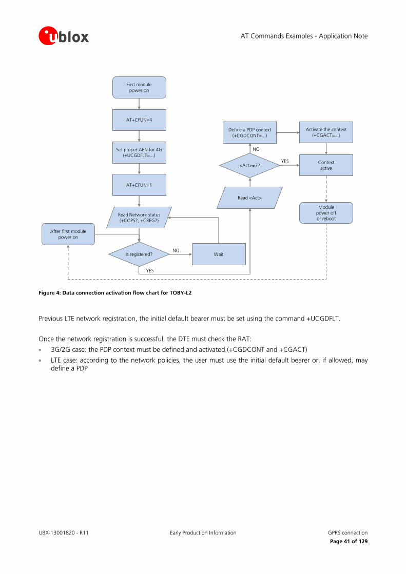
AT Commands Examples - Application Note
UBX-13001820 - R11 Early Production Information GPRS connection
Page 41 of 129
Read <Act>
AT+CFUN=4
Set proper APN for 4G
(+UCGDFLT=...)
AT+CFUN=1
First module
power on
Read Network status
(+COPS?, +CREG?)
Is registered? Wait
After first module
power on
Module
power offor reboot
<Act>=7?
Define a PDP context
(+CGDCONT=...)
Activate the context
(+CGACT=...)
Context
active
NO
YES
NO
YES
Figure 4: Data connection activation flow chart for TOBY-L2
Previous LTE network registration, the initial default bearer must be set using the command +UCGDFLT.
Once the network registration is successful, the DTE must check the RAT:
3G/2G case: the PDP context must be defined and activated (+CGDCONT and +CGACT)
LTE case: according to the network policies, the user must use the initial default bearer or, if allowed, may define a PDP
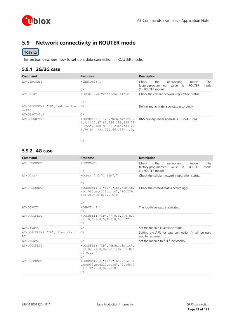
AT Commands Examples - Application Note
UBX-13001820 - R11 Early Production Information GPRS connection
Page 42 of 129
5.9 Network connectivity in ROUTER mode
This section describes how to set up a data connection in ROUTER mode.
5.9.1 2G/3G case
Command Response Description
AT+UBMCONF? +UBMCONF: 1
OK
Check the networking mode. The factory-programmed value is ROUTER mode (1=ROUTER mode).
AT+COPS? +COPS: 0,0,"vodafone IT",2
OK
Check the cellular network registration status.
AT+CGDCONT=1,"IP","web.omnite
l.it"
OK Define and activate a context accordingly
AT+CGACT=1,1 OK
AT+CGCONTRDP +CGCONTRDP: 1,0,"web.omnitel.
it","100.87.85.236.255.255.25
5.255","100.87.85.236","83.22
4.70.94","83.224.66.138",,,0,
0
OK
DNS primary server address is 83.224.70.94.
5.9.2 4G case
Command Response Description
AT+UBMCONF? +UBMCONF: 1
OK
Check the networking mode. The factory-programmed value is ROUTER mode
(1=ROUTER mode).
AT+COPS? +COPS: 0,0,"I TIM",7
OK
Check the cellular network registration status.
AT+CGDCONT? +CGDCONT: 4,"IP","lte.tim.it.
mnc 001.mcc222.gprs","10.226.
128.209",0,0,0,0,0,0
OK
Check the context status accordingly.
AT+CGACT? +CGACT: 4,1
OK
The fourth context is activated.
AT+UCGDFLT? +UCGDFLT: "IP","",0,0,0,0,0,0
,0, 0,0,1,0,0,1,0,0,0,0,""
OK
AT+CFUN=4 OK Set the module in airplane mode.
AT+UCGDFLT=1,"IP","ibox.tim.i
t"
OK Setting the APN for data connection (it will be used also for signaling …).
AT+CFUN=1 OK Set the module to full functionality.
AT+UCGDFLT? +UCGDFLT: "IP","ibox.tim.it",
0,0,0,0,1,0,0,0,0,1,0,0,1,0,0
,0,0,,,""
OK
AT+CGDCONT? +CGDCONT: 4,"IP","ibox.tim.it
.mnc001.mcc222.gprs","5.168.2
09.178",0,0,0,0,0,0
OK
TOBY-L2
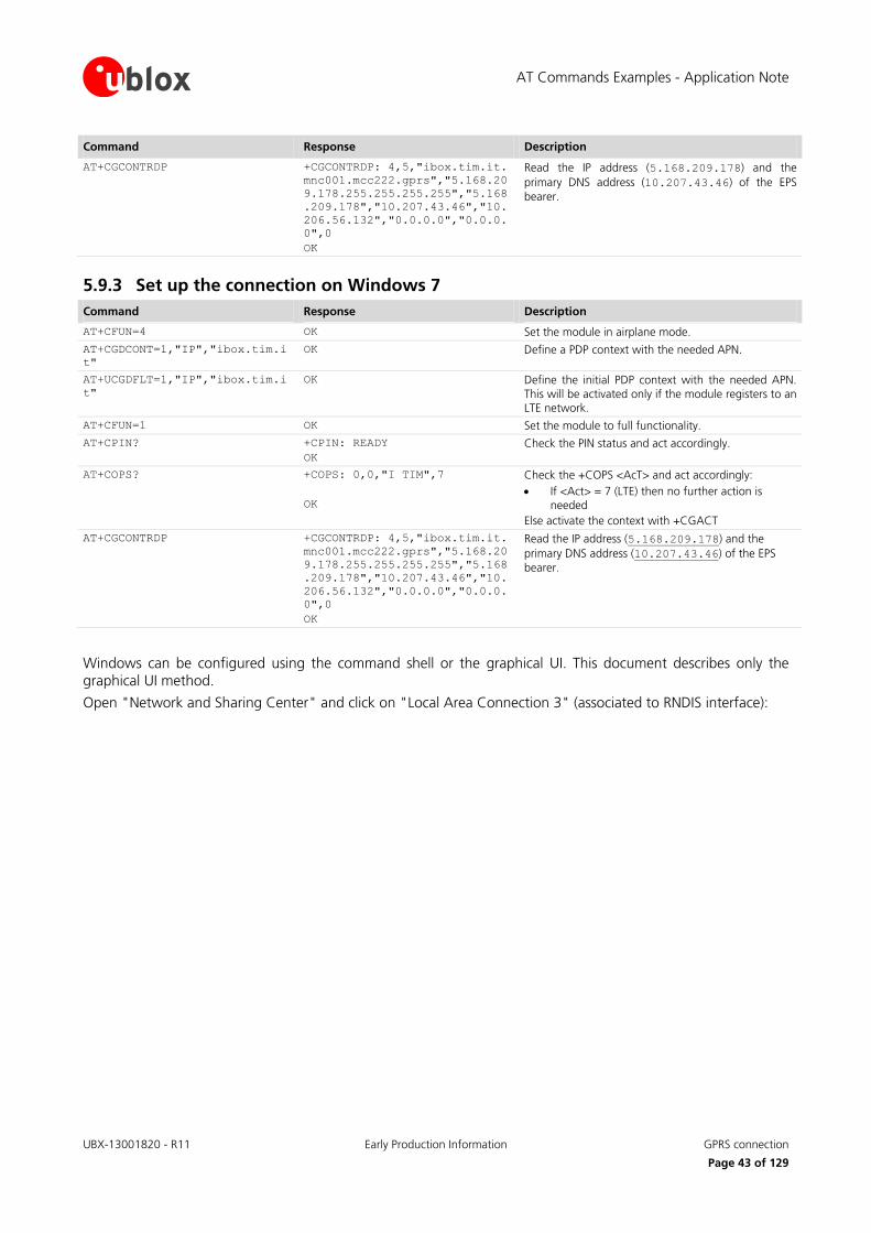
AT Commands Examples - Application Note
UBX-13001820 - R11 Early Production Information GPRS connection
Page 43 of 129
Command Response Description
AT+CGCONTRDP +CGCONTRDP: 4,5,"ibox.tim.it.
mnc001.mcc222.gprs","5.168.20
9.178.255.255.255.255","5.168
.209.178","10.207.43.46","10.
206.56.132","0.0.0.0","0.0.0.
0",0
OK
Read the IP address (5.168.209.178) and the
primary DNS address (10.207.43.46) of the EPS
bearer.
5.9.3 Set up the connection on Windows 7
Command Response Description
AT+CFUN=4 OK Set the module in airplane mode.
AT+CGDCONT=1,"IP","ibox.tim.i
t"
OK Define a PDP context with the needed APN.
AT+UCGDFLT=1,"IP","ibox.tim.i
t"
OK Define the initial PDP context with the needed APN.
This will be activated only if the module registers to an LTE network.
AT+CFUN=1 OK Set the module to full functionality.
AT+CPIN? +CPIN: READY
OK
Check the PIN status and act accordingly.
AT+COPS? +COPS: 0,0,"I TIM",7
OK
Check the +COPS <AcT> and act accordingly:
If <Act> = 7 (LTE) then no further action is needed
Else activate the context with +CGACT
AT+CGCONTRDP +CGCONTRDP: 4,5,"ibox.tim.it.
mnc001.mcc222.gprs","5.168.20
9.178.255.255.255.255","5.168
.209.178","10.207.43.46","10.
206.56.132","0.0.0.0","0.0.0.
0",0
OK
Read the IP address (5.168.209.178) and the
primary DNS address (10.207.43.46) of the EPS
bearer.
Windows can be configured using the command shell or the graphical UI. This document describes only the graphical UI method.
Open "Network and Sharing Center" and click on "Local Area Connection 3" (associated to RNDIS interface):
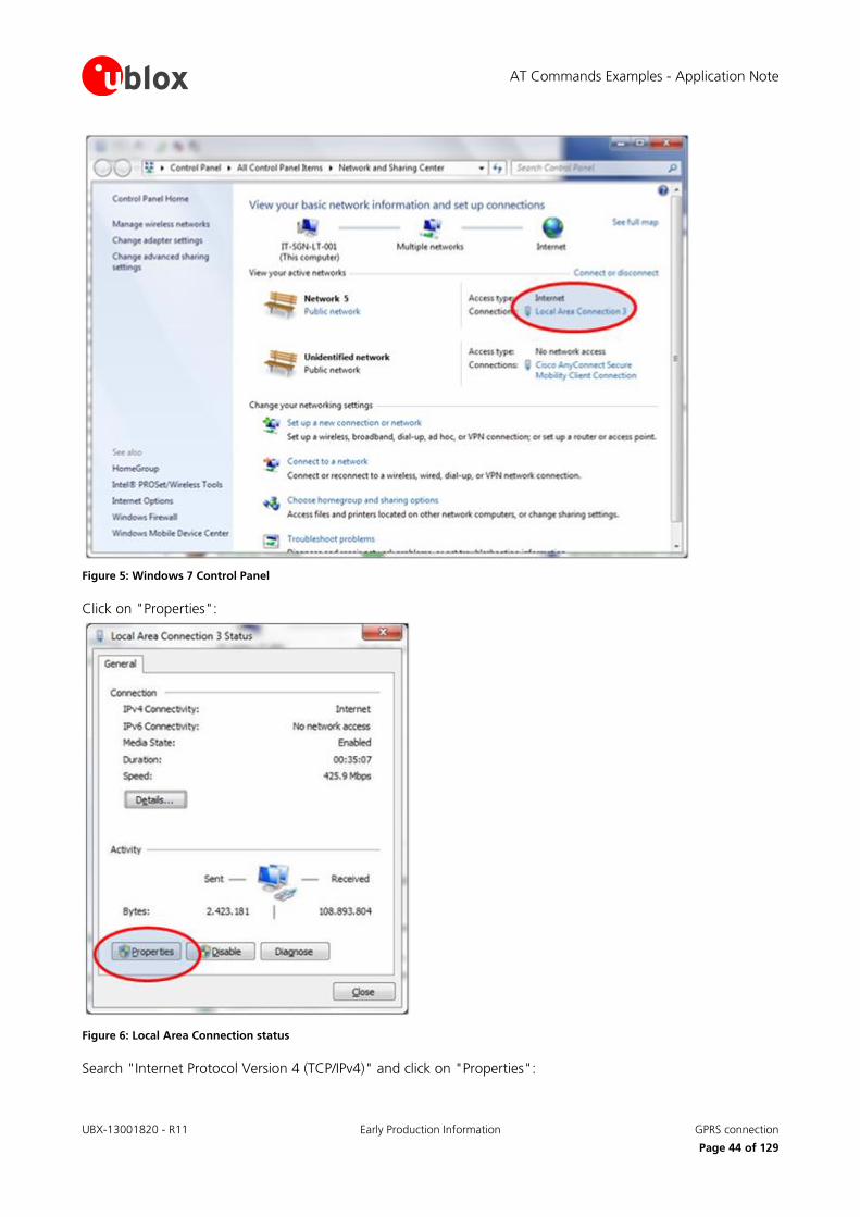
AT Commands Examples - Application Note
UBX-13001820 - R11 Early Production Information GPRS connection
Page 44 of 129
Figure 5: Windows 7 Control Panel
Click on "Properties":
Figure 6: Local Area Connection status
Search "Internet Protocol Version 4 (TCP/IPv4)" and click on "Properties":
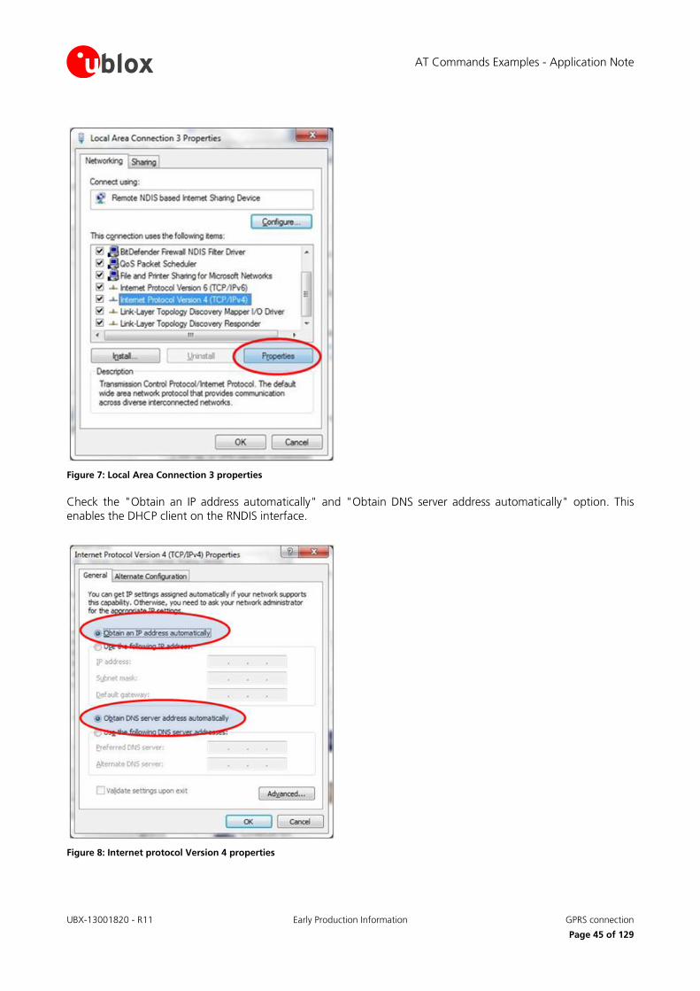
AT Commands Examples - Application Note
UBX-13001820 - R11 Early Production Information GPRS connection
Page 45 of 129
Figure 7: Local Area Connection 3 properties
Check the "Obtain an IP address automatically" and "Obtain DNS server address automatically" option. This enables the DHCP client on the RNDIS interface.
Figure 8: Internet protocol Version 4 properties

AT Commands Examples - Application Note
UBX-13001820 - R11 Early Production Information GPRS connection
Page 46 of 129
If it is not possible to access the Internet, then manually set the DNS server address. For example, use the DNS server provided by the cellular network (83.224.70.94 or 10.207.43.46), or Google DNS servers (8.8.8.8 or 8.8.4.4):
Figure 9: Set the preferred DNS
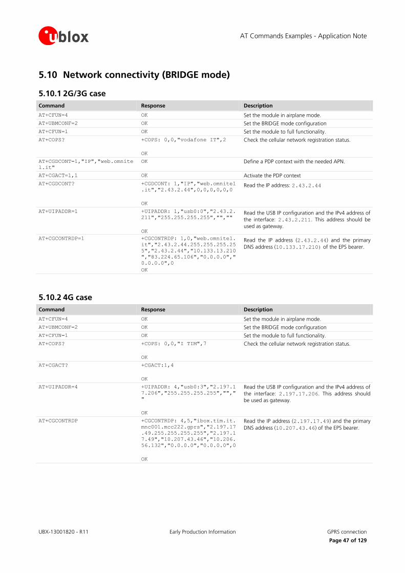
AT Commands Examples - Application Note
UBX-13001820 - R11 Early Production Information GPRS connection
Page 47 of 129
5.10 Network connectivity (BRIDGE mode)
5.10.1 2G/3G case
Command Response Description
AT+CFUN=4 OK Set the module in airplane mode.
AT+UBMCONF=2 OK Set the BRIDGE mode configuration
AT+CFUN=1 OK Set the module to full functionality.
AT+COPS? +COPS: 0,0,"vodafone IT",2
OK
Check the cellular network registration status.
AT+CGDCONT=1,"IP","web.omnite
l.it"
OK Define a PDP context with the needed APN.
AT+CGACT=1,1 OK Activate the PDP context
AT+CGDCONT? +CGDCONT: 1,"IP","web.omnitel
.it","2.43.2.44",0,0,0,0,0,0
OK
Read the IP address: 2.43.2.44
AT+UIPADDR=1 +UIPADDR: 1,"usb0:0","2.43.2.
211","255.255.255.255","",""
OK
Read the USB IP configuration and the IPv4 address of
the interface: 2.43.2.211. This address should be
used as gateway.
AT+CGCONTRDP=1 +CGCONTRDP: 1,0,"web.omnitel.
it","2.43.2.44.255.255.255.25
5","2.43.2.44","10.133.13.210
","83.224.65.106","0.0.0.0","
0.0.0.0",0
OK
Read the IP address (2.43.2.44) and the primary
DNS address (10.133.17.210) of the EPS bearer.
5.10.2 4G case
Command Response Description
AT+CFUN=4 OK Set the module in airplane mode.
AT+UBMCONF=2 OK Set the BRIDGE mode configuration
AT+CFUN=1 OK Set the module to full functionality.
AT+COPS? +COPS: 0,0,"I TIM",7
OK
Check the cellular network registration status.
AT+CGACT? +CGACT:1,4
OK
AT+UIPADDR=4 +UIPADDR: 4,"usb0:3","2.197.1
7.206","255.255.255.255","","
"
OK
Read the USB IP configuration and the IPv4 address of
the interface: 2.197.17.206. This address should
be used as gateway.
AT+CGCONTRDP +CGCONTRDP: 4,5,"ibox.tim.it.
mnc001.mcc222.gprs","2.197.17
.49.255.255.255.255","2.197.1
7.49","10.207.43.46","10.206.
56.132","0.0.0.0","0.0.0.0",0
OK
Read the IP address (2.197.17.49) and the primary
DNS address (10.207.43.46) of the EPS bearer.
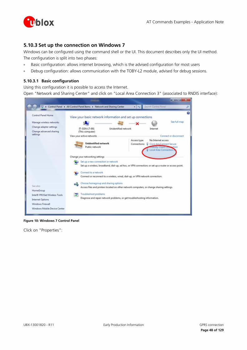
AT Commands Examples - Application Note
UBX-13001820 - R11 Early Production Information GPRS connection
Page 48 of 129
5.10.3 Set up the connection on Windows 7
Windows can be configured using the command shell or the UI. This document describes only the UI method.
The configuration is split into two phases:
Basic configuration: allows internet browsing, which is the advised configuration for most users
Debug configuration: allows communication with the TOBY-L2 module, advised for debug sessions.
5.10.3.1 Basic configuration
Using this configuration it is possible to access the Internet.
Open "Network and Sharing Center" and click on "Local Area Connection 3" (associated to RNDIS interface):
Figure 10: Windows 7 Control Panel
Click on "Properties":
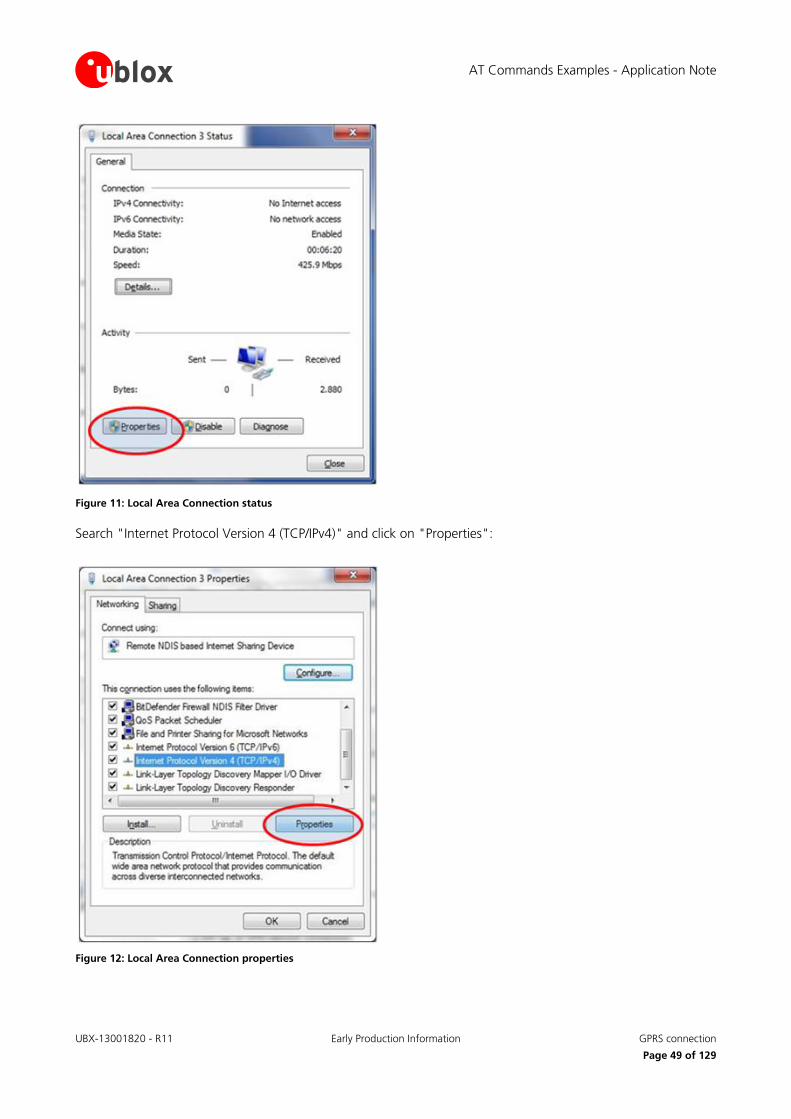
AT Commands Examples - Application Note
UBX-13001820 - R11 Early Production Information GPRS connection
Page 49 of 129
Figure 11: Local Area Connection status
Search "Internet Protocol Version 4 (TCP/IPv4)" and click on "Properties":
Figure 12: Local Area Connection properties
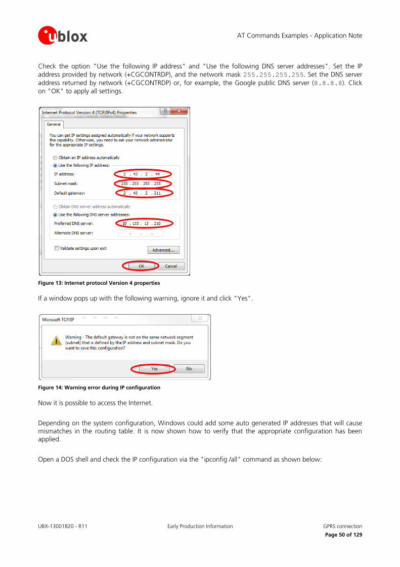
AT Commands Examples - Application Note
UBX-13001820 - R11 Early Production Information GPRS connection
Page 50 of 129
Check the option "Use the following IP address" and "Use the following DNS server addresses". Set the IP
address provided by network (+CGCONTRDP), and the network mask 255.255.255.255. Set the DNS server
address returned by network (+CGCONTRDP) or, for example, the Google public DNS server (8.8.8.8). Click
on "OK" to apply all settings.
Figure 13: Internet protocol Version 4 properties
If a window pops up with the following warning, ignore it and click "Yes".
Figure 14: Warning error during IP configuration
Now it is possible to access the Internet.
Depending on the system configuration, Windows could add some auto generated IP addresses that will cause mismatches in the routing table. It is now shown how to verify that the appropriate configuration has been applied.
Open a DOS shell and check the IP configuration via the "ipconfig /all" command as shown below:
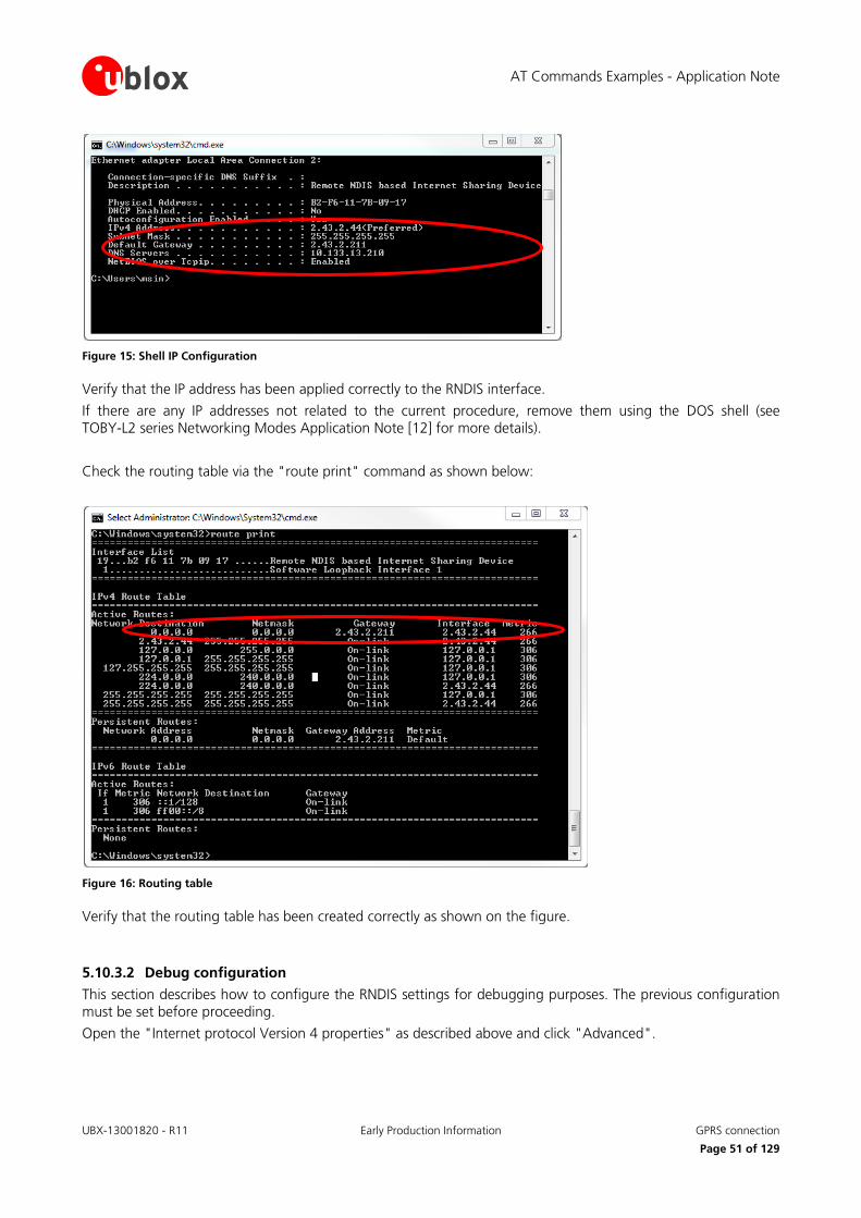
AT Commands Examples - Application Note
UBX-13001820 - R11 Early Production Information GPRS connection
Page 51 of 129
Figure 15: Shell IP Configuration
Verify that the IP address has been applied correctly to the RNDIS interface.
If there are any IP addresses not related to the current procedure, remove them using the DOS shell (see TOBY-L2 series Networking Modes Application Note [12] for more details).
Check the routing table via the "route print" command as shown below:
Figure 16: Routing table
Verify that the routing table has been created correctly as shown on the figure.
5.10.3.2 Debug configuration
This section describes how to configure the RNDIS settings for debugging purposes. The previous configuration must be set before proceeding.
Open the "Internet protocol Version 4 properties" as described above and click "Advanced".

AT Commands Examples - Application Note
UBX-13001820 - R11 Early Production Information GPRS connection
Page 52 of 129
Figure 17: Internet protocol Version 4 properties
Click on "Add" to add an ‘alias’.
Figure 18: Advanced TCP/IP settings
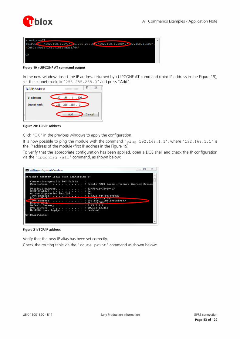
AT Commands Examples - Application Note
UBX-13001820 - R11 Early Production Information GPRS connection
Page 53 of 129
Figure 19 +UIPCONF AT command output
In the new window, insert the IP address returned by +UIPCONF AT command (third IP address in the Figure 19),
set the subnet mask to "255.255.255.0" and press "Add".
Figure 20: TCP/IP address
Click "OK" in the previous windows to apply the configuration.
It is now possible to ping the module with the command "ping 192.168.1.1", where "192.168.1.1" is
the IP address of the module (first IP address in the Figure 19).
To verify that the appropriate configuration has been applied, open a DOS shell and check the IP configuration
via the "ipconfig /all" command, as shown below:
Figure 21: TCP/IP address
Verify that the new IP alias has been set correctly.
Check the routing table via the "route print" command as shown below:

AT Commands Examples - Application Note
UBX-13001820 - R11 Early Production Information GPRS connection
Page 54 of 129
Figure 22: Routing table
Verify that the routing has been set correctly, as shown on the figure.
5.10.3.3 Restore previous windows configuration
To stop the data connectivity, delete all the aliases added to the RNDIS interface:
remove the alias from "Advanced TCP/IP Settings":
o in the provided example remove the alias associated to address "192.168.1.100"
check the option "Obtain an IP address automatically" and "Obtain DNS server address automatically" option
5.10.4 Using sockets on an already activated PDP context
Command Response Description
The network assigns IPv4v6 address
AT+CGDCONT=8,"IPV4V6","apn_nam
e"
OK Define the PDP context 8 with PDP type "IPV4V6" and APN "apn_name".
AT+CGACT=1,8 OK PDP context 8 activation: IPv4v6 address assigned by the network.
AT+CGDCONT? +CGDCONT: 8,"IPV4V6","apn_nam
e","100.108.232.233 38.0.16.3
.177.33.116.198.0.0.0.3.107.2
32.191.1",0,0,0,0,0,0
OK
Return both IPv4 (100.108.232.233) and IPv6 (38.0.16.3.177.33.116.198.0.0.0.3.107.232.191.1) addresses.
AT+UPSD=0,100,8 OK Profile #0 is mapped on CID=8.
TOBY-L2
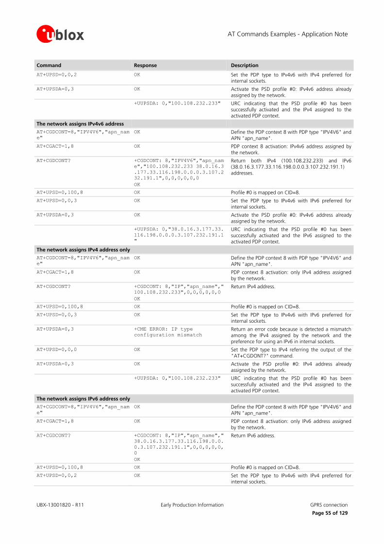
AT Commands Examples - Application Note
UBX-13001820 - R11 Early Production Information GPRS connection
Page 55 of 129
Command Response Description
AT+UPSD=0,0,2 OK Set the PDP type to IPv4v6 with IPv4 preferred for internal sockets.
AT+UPSDA=0,3 OK Activate the PSD profile #0: IPv4v6 address already assigned by the network.
+UUPSDA: 0,"100.108.232.233" URC indicating that the PSD profile #0 has been successfully activated and the IPv4 assigned to the activated PDP context.
The network assigns IPv4v6 address
AT+CGDCONT=8,"IPV4V6","apn_nam
e"
OK Define the PDP context 8 with PDP type "IPV4V6" and APN "apn_name".
AT+CGACT=1,8 OK PDP context 8 activation: IPv4v6 address assigned by the network.
AT+CGDCONT? +CGDCONT: 8,"IPV4V6","apn_nam
e","100.108.232.233 38.0.16.3
.177.33.116.198.0.0.0.3.107.2
32.191.1",0,0,0,0,0,0
OK
Return both IPv4 (100.108.232.233) and IPv6 (38.0.16.3.177.33.116.198.0.0.0.3.107.232.191.1) addresses.
AT+UPSD=0,100,8 OK Profile #0 is mapped on CID=8.
AT+UPSD=0,0,3 OK Set the PDP type to IPv4v6 with IPv6 preferred for internal sockets.
AT+UPSDA=0,3 OK Activate the PSD profile #0: IPv4v6 address already assigned by the network.
+UUPSDA: 0,"38.0.16.3.177.33.
116.198.0.0.0.3.107.232.191.1
"
URC indicating that the PSD profile #0 has been successfully activated and the IPv6 assigned to the activated PDP context.
The network assigns IPv4 address only
AT+CGDCONT=8,"IPV4V6","apn_nam
e"
OK Define the PDP context 8 with PDP type "IPV4V6" and APN "apn_name".
AT+CGACT=1,8 OK PDP context 8 activation: only IPv4 address assigned by the network.
AT+CGDCONT? +CGDCONT: 8,"IP","apn_name","
100.108.232.233",0,0,0,0,0,0
OK
Return IPv4 address.
AT+UPSD=0,100,8 OK Profile #0 is mapped on CID=8.
AT+UPSD=0,0,3 OK Set the PDP type to IPv4v6 with IPv6 preferred for internal sockets.
AT+UPSDA=0,3 +CME ERROR: IP type
configuration mismatch
Return an error code because is detected a mismatch among the IPv4 assigned by the network and the preference for using an IPv6 in internal sockets.
AT+UPSD=0,0,0 OK Set the PDP type to IPv4 referring the output of the "AT+CGDONT?" command.
AT+UPSDA=0,3 OK Activate the PSD profile #0: IPv4 address already assigned by the network.
+UUPSDA: 0,"100.108.232.233" URC indicating that the PSD profile #0 has been successfully activated and the IPv4 assigned to the
activated PDP context.
The network assigns IPv6 address only
AT+CGDCONT=8,"IPV4V6","apn_nam
e"
OK Define the PDP context 8 with PDP type "IPV4V6" and APN "apn_name".
AT+CGACT=1,8 OK PDP context 8 activation: only IPv6 address assigned by the network.
AT+CGDCONT? +CGDCONT: 8,"IP","apn_name","
38.0.16.3.177.33.116.198.0.0.
0.3.107.232.191.1",0,0,0,0,0,
0
OK
Return IPv6 address.
AT+UPSD=0,100,8 OK Profile #0 is mapped on CID=8.
AT+UPSD=0,0,2 OK Set the PDP type to IPv4v6 with IPv4 preferred for internal sockets.

AT Commands Examples - Application Note
UBX-13001820 - R11 Early Production Information GPRS connection
Page 56 of 129
Command Response Description
AT+UPSDA=0,3 +CME ERROR: IP type
configuration mismatch
Return an error code because is detected a mismatch among the IPv6 assigned by the network and the
preference for using an IPv4 in internal sockets.
AT+UPSD=0,0,1 OK Set the PDP type to IPv6 referring the output of the
"AT+CGDONT?" command.
AT+UPSDA=0,3 OK Activate the PSD profile #0: IPv6 address already assigned by the network.
+UUPSDA: 0,"38.0.16.3.177.33.
116.198.0.0.0.3.107.232.191.1
"
URC indicating that the PSD profile #0 has been successfully activated and the IPv6 assigned to the
activated PDP context.
5.10.5 PDP context activation by means of +UPSDA, impact of <PDP_type> on address
Command Response Description
AT+UPSD=0,1,"apn_name" OK Set up APN for the PSD profile #0.
AT+UPSD=0,0,3 OK Set the PDP type to IPv4v6 with IPv6 preferred for internal sockets.
AT+UPSDA=0,3 +CME ERROR: APN configuration
mismatch
Return an error code because in detected a mismatch: in fact the network assigns only the IPv4, while the
preference is for using IPv6 in internal sockets.
AT+UPSD=0,0,0 OK Change the PDP type to IPv4.
AT+UPSDA=0,3 OK Activate the PSD profile #0: only IPv4 assigned by the network.
+UUPSDA: 0,"100.108.232.233" URC indicating that the PSD profile #0 has been successfully activated and the IPv4 assigned to the activated PDP context.
TOBY-L2
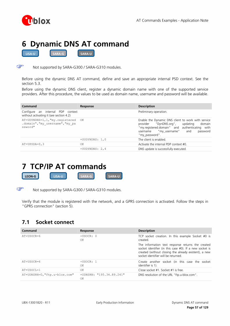
AT Commands Examples - Application Note
UBX-13001820 - R11 Early Production Information Dynamic DNS AT command
Page 57 of 129
6 Dynamic DNS AT command
Not supported by SARA-G300 / SARA-G310 modules.
Before using the dynamic DNS AT command, define and save an appropriate internal PSD context. See the section 5.3.
Before using the dynamic DNS client, register a dynamic domain name with one of the supported service providers. After this procedure, the values to be used as domain name, username and password will be available.
Command Response Description
Configure an internal PDP context without activating it (see section 4.2)
Preliminary operation.
AT+UDYNDNS=1,1,"my.registered
.domain","my_username","my_pa
ssword"
OK Enable the Dynamic DNS client to work with service provider "DynDNS.org", updating domain
"my.registered.domain" and authenticating with username "my_username" and password "my_password".
+UUDYNDNS: 1,0 The client is enabled.
AT+UPSDA=0,3 OK Activate the internal PDP context #0.
+UUDYNDNS: 2,4 DNS update is successfully executed.
7 TCP/IP AT commands
Not supported by SARA-G300 / SARA-G310 modules.
Verify that the module is registered with the network, and a GPRS connection is activated. Follow the steps in "GPRS connection" (section 5).
7.1 Socket connect
Command Response Description
AT+USOCR=6 +USOCR: 0
OK
TCP socket creation. In this example Socket #0 is created.
The information text response returns the created socket identifier (in this case #0). If a new socket is
created (without closing the already existent), a new socket identifier will be returned.
AT+USOCR=6 +USOCR: 1
OK
Create another socket (in this case the socket identifier is 1).
AT+USOCL=1 OK Close socket #1. Socket #1 is free.
AT+UDNSRN=0,"ftp.u-blox.com" +UDNSRN: "195.34.89.241"
OK
DNS resolution of the URL "ftp.u-blox.com".
SARA-U SARA-G LISA-U LEON-G
SARA-U SARA-G LISA-U

AT Commands Examples - Application Note
UBX-13001820 - R11 Early Production Information TCP/IP AT commands
Page 58 of 129
Command Response Description
AT+USOCO=0,"195.34.89.241",21 OK Connect socket #0 to port 21 of a remote host with IP address 195.34.89.241.
The connection is now uniquely associated to the socket. Socket is now ready for read / write
operations.
AT+USOCO=0,"195.34.89.241",21 ERROR
+UUSOCL: 0
If the connection is not successfully performed, an error result code is returned and the socket used for
the connection attempt is closed. The notification is provided by +UUSOCL URC.
7.2 Socket listening
Command Response Description
AT+USOCR=6 +USOCR: 0
OK
TCP socket creation with ID #0.
AT+USOLI=0,1099 OK Set socket in listening mode on port 1099.
WARNING: The ability to reach the opened port on the server depends also on the network
operator. Some network operators do not allow incoming connection on opened TCP/UDP port.
+UUSOLI: 1,"151.9.34.66",3991
2,0,"151.9.34.74",1099
When a connection request arrives from a remote host, a new socket is created with the first integer identifier available. In this example socket ID is #1.
+UUSOLI indicates:
1: the new socket created. Incoming data from the
established connection will be received on this socket. Data to be sent must be written into this socket
151.9.34.66: IP of the remote server
39912: service port
0: listening socket. It is the socket identifier specified
with the AT+USOLI command
151.9.34.74: module IP address
1099: listening port assigned to the connection. Configured with AT+USOLI command
Socket #1 is now ready for reading/writing data
+UUSORD: 1,18 18 bytes of incoming data over the previously established connection.
The incoming data will always be sent on the related socket.
7.3 Socket write
7.3.1 Binary mode
Command Response Description
AT+USOWR=0,2 @ Request to write 2 data bytes into socket #0. Wait
"@" symbol indicating the data prompt is now open (AT commands are not allowed in data prompt).
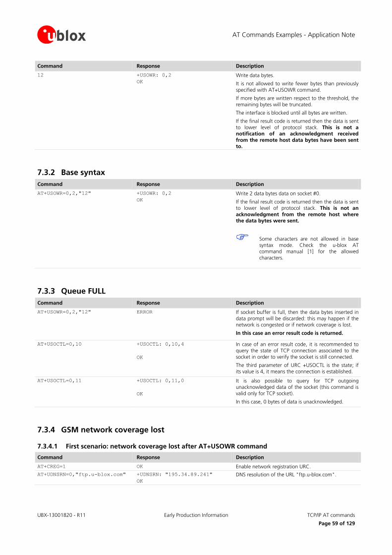
AT Commands Examples - Application Note
UBX-13001820 - R11 Early Production Information TCP/IP AT commands
Page 59 of 129
Command Response Description
12 +USOWR: 0,2
OK
Write data bytes.
It is not allowed to write fewer bytes than previously
specified with AT+USOWR command.
If more bytes are written respect to the threshold, the
remaining bytes will be truncated.
The interface is blocked until all bytes are written.
If the final result code is returned then the data is sent
to lower level of protocol stack. This is not a notification of an acknowledgment received
from the remote host data bytes have been sent to.
7.3.2 Base syntax
Command Response Description
AT+USOWR=0,2,"12" +USOWR: 0,2
OK
Write 2 data bytes data on socket #0.
If the final result code is returned then the data is sent to lower level of protocol stack. This is not an
acknowledgment from the remote host where the data bytes were sent.
Some characters are not allowed in base syntax mode. Check the u-blox AT command manual [1] for the allowed
characters.
7.3.3 Queue FULL
Command Response Description
AT+USOWR=0,2,"12" ERROR If socket buffer is full, then the data bytes inserted in
data prompt will be discarded: this may happen if the network is congested or if network coverage is lost.
In this case an error result code is returned.
AT+USOCTL=0,10 +USOCTL: 0,10,4
OK
In case of an error result code, it is recommended to query the state of TCP connection associated to the
socket in order to verify the socket is still connected.
The third parameter of URC +USOCTL is the state; if
its value is 4, it means the connection is established.
AT+USOCTL=0,11 +USOCTL: 0,11,0
OK
It is also possible to query for TCP outgoing
unacknowledged data of the socket (this command is valid only for TCP socket).
In this case, 0 bytes of data is unacknowledged.
7.3.4 GSM network coverage lost
7.3.4.1 First scenario: network coverage lost after AT+USOWR command
Command Response Description
AT+CREG=1 OK Enable network registration URC.
AT+UDNSRN=0,"ftp.u-blox.com" +UDNSRN: "195.34.89.241"
OK
DNS resolution of the URL "ftp.u-blox.com".
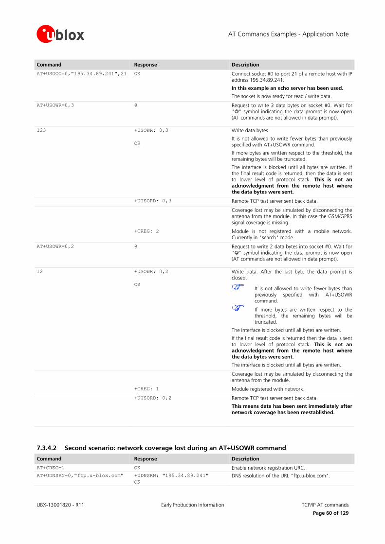
AT Commands Examples - Application Note
UBX-13001820 - R11 Early Production Information TCP/IP AT commands
Page 60 of 129
Command Response Description
AT+USOCO=0,"195.34.89.241",21 OK Connect socket #0 to port 21 of a remote host with IP address 195.34.89.241.
In this example an echo server has been used.
The socket is now ready for read / write data.
AT+USOWR=0,3 @ Request to write 3 data bytes on socket #0. Wait for "@" symbol indicating the data prompt is now open (AT commands are not allowed in data prompt).
123 +USOWR: 0,3
OK
Write data bytes.
It is not allowed to write fewer bytes than previously specified with AT+USOWR command.
If more bytes are written respect to the threshold, the remaining bytes will be truncated.
The interface is blocked until all bytes are written. If the final result code is returned, then the data is sent to lower level of protocol stack. This is not an
acknowledgment from the remote host where the data bytes were sent.
+UUSORD: 0,3 Remote TCP test server sent back data.
Coverage lost may be simulated by disconnecting the antenna from the module. In this case the GSM/GPRS signal coverage is missing.
+CREG: 2 Module is not registered with a mobile network. Currently in "search" mode.
AT+USOWR=0,2 @ Request to write 2 data bytes into socket #0. Wait for "@" symbol indicating the data prompt is now open (AT commands are not allowed in data prompt).
12 +USOWR: 0,2
OK
Write data. After the last byte the data prompt is closed.
It is not allowed to write fewer bytes than previously specified with AT+USOWR command.
If more bytes are written respect to the threshold, the remaining bytes will be truncated.
The interface is blocked until all bytes are written.
If the final result code is returned then the data is sent
to lower level of protocol stack. This is not an acknowledgment from the remote host where
the data bytes were sent.
The interface is blocked until all bytes are written.
Coverage lost may be simulated by disconnecting the antenna from the module.
+CREG: 1 Module registered with network.
+UUSORD: 0,2 Remote TCP test server sent back data.
This means data has been sent immediately after
network coverage has been reestablished.
7.3.4.2 Second scenario: network coverage lost during an AT+USOWR command
Command Response Description
AT+CREG=1 OK Enable network registration URC.
AT+UDNSRN=0,"ftp.u-blox.com" +UDNSRN: "195.34.89.241"
OK
DNS resolution of the URL "ftp.u-blox.com".
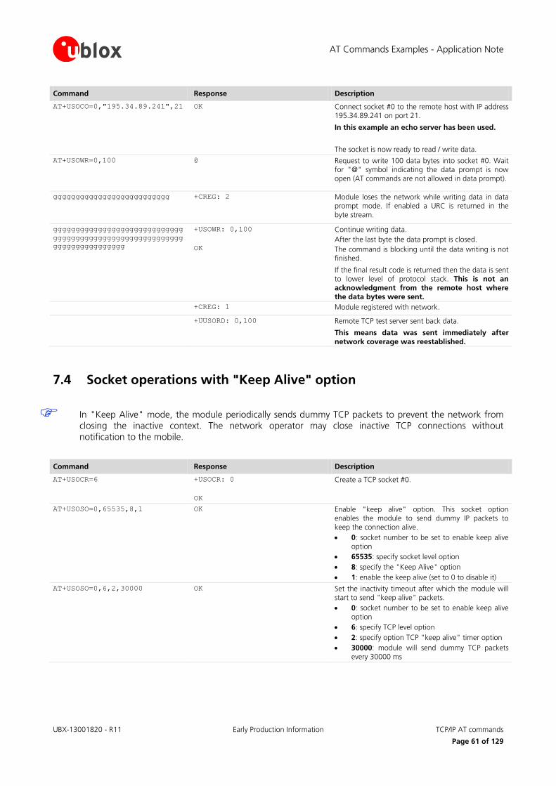
AT Commands Examples - Application Note
UBX-13001820 - R11 Early Production Information TCP/IP AT commands
Page 61 of 129
Command Response Description
AT+USOCO=0,"195.34.89.241",21 OK Connect socket #0 to the remote host with IP address 195.34.89.241 on port 21.
In this example an echo server has been used.
The socket is now ready to read / write data.
AT+USOWR=0,100 @ Request to write 100 data bytes into socket #0. Wait for "@" symbol indicating the data prompt is now open (AT commands are not allowed in data prompt).
gggggggggggggggggggggggggg +CREG: 2 Module loses the network while writing data in data prompt mode. If enabled a URC is returned in the byte stream.
ggggggggggggggggggggggggggggg
ggggggggggggggggggggggggggggg
gggggggggggggggg
+USOWR: 0,100
OK
Continue writing data.
After the last byte the data prompt is closed.
The command is blocking until the data writing is not finished.
If the final result code is returned then the data is sent to lower level of protocol stack. This is not an
acknowledgment from the remote host where the data bytes were sent.
+CREG: 1 Module registered with network.
+UUSORD: 0,100 Remote TCP test server sent back data.
This means data was sent immediately after
network coverage was reestablished.
7.4 Socket operations with "Keep Alive" option
In "Keep Alive" mode, the module periodically sends dummy TCP packets to prevent the network from closing the inactive context. The network operator may close inactive TCP connections without notification to the mobile.
Command Response Description
AT+USOCR=6 +USOCR: 0
OK
Create a TCP socket #0.
AT+USOSO=0,65535,8,1 OK Enable "keep alive" option. This socket option enables the module to send dummy IP packets to
keep the connection alive.
0: socket number to be set to enable keep alive option
65535: specify socket level option
8: specify the "Keep Alive" option
1: enable the keep alive (set to 0 to disable it)
AT+USOSO=0,6,2,30000 OK Set the inactivity timeout after which the module will start to send "keep alive" packets.
0: socket number to be set to enable keep alive option
6: specify TCP level option
2: specify option TCP "keep alive" timer option
30000: module will send dummy TCP packets every 30000 ms

AT Commands Examples - Application Note
UBX-13001820 - R11 Early Production Information TCP/IP AT commands
Page 62 of 129
7.5 Socket read
First scenario
Command Response Description
+UUSORD: 0,2
Remote server sends 2 data bytes on socket #0.
A URC is returned indicating the socket on which the
data is received and the total amount of data received.
AT+USORD=0,2 +USORD: 0,2,"ar"
OK
Read data. Data is returned between quotation marks.
Second scenario
Command Response Description
+UUSORD: 0,30
Remote server sends 30 data bytes on socket #0.
If a socket buffer is empty, +UUSORD URC indicates a
TCP packet has been received from the remote host the socket is connected to and the amount of data
bytes of the packet.
AT+USORD=0,10 +USORD: 0,10,"hfgyrhgfty"
OK
+UUSORD: 0,20
Read only part of data (in this example 10 bytes of data are read).
Data is returned between quotation marks.
+UUSORD URC indicates the total amount of data bytes stored in the buffer after last AT+USORD execution. In this example 20 bytes are stored in the
buffer.
Third scenario
Command Response Description
+UUSORD: 0,30
Remote server sends 30 data bytes on socket #0.
If a socket buffer is empty +UUSORD URC indicates a TCP packet has been received from the remote host
the socket is connected to and the amount of data bytes of the packet.
AT+USORD=0,10 +USORD: 0,10,"hfgyrhgfty"
OK
+UUSORD: 0,25
Only part of the data bytes (10 bytes in this example) are read.
The data is returned between quotation marks.
Remote server sent more data after the first part was
received. +UUSORD URC indicates the total amount of data bytes stored the buffer after the last AT+USORD
execution. In this example 25 bytes are stored in the buffer.
AT+USORD=0,10 +USORD: 0,10,"hfgbchs7[o"
OK
+UUSORD: 0,34
Only part of the data bytes (10 bytes in this example) is read.
Data is returned between quotation marks.
Remote server sent more data. +UUSORD URC
indicates the total amount of data bytes stored the buffer after the last AT+USORD execution. In this
example 34 bytes are stored in the buffer.
AT+USORD=0,34 +USORD: 0,34,"jghfbv74ksHDFUE
çpjè0’@èpyujfnvhfyù"
OK
All the bytes are read.
AT+USORD=0,0 +USORD: 0,0
OK
Verifies how much unread data is in the buffer. In this example 0 bytes are in socket #0.
AT Commands Examples - Application Note
UBX-13001820 - R11 Early Production Information TCP/IP AT commands
Page 63 of 129
Fourth scenario
Command Response Description
+UUSORD: 0,30
Remote host sends 30 bytes of data on socket #0.
If a socket buffer is empty +UUSORD URC indicates a
TCP packet has been received from the remote host the socket is connected to and the amount of data
bytes of the packet.
AT+USORD=0,10 +USORD: 0,10,"hfgyrhgfty"
OK
+UUSORD: 0,25
Only part of the data bytes (10 bytes in this example) are read.
Data is returned between quotation marks.
Remote server sent other data after the first data
bytes had been received. +UUSORD URC indicates the total amount of data bytes stored the buffer after last
AT+USORD execution. In this example 25 bytes are in the buffer.
Remote host closes the TCP connection associated to socket #0.
AT+USOWR=0,3 @ Request to write 3 data bytes into socket #0. Wait for "@" symbol indicating the data prompt is now open.
123 +USOWR: 0,0
OK
Write data. After the last byte the data prompt is closed.
It is not allowed to write fewer bytes than previously specified with AT+USOWR
command.
If more bytes are written respect to the threshold, the remaining bytes will be
truncated.
The interface is blocked until all bytes are written.
+USOWR: 0,0 URC indicates 0 bytes have been sent
to remote host. This means the TCP connection is now closed.
AT+USORD=0,25 +USORD: 0,25,"23dfgt5uhj89ikd
ftevlpazwe"
OK
Read the remaining data bytes still stored in the buffer of socket #0.
+UUSOCL: 0 The URC indicates the TCP connection associated to socket #0 is now closed and socket #0 is cleared.
7.6 Socket state
For a detailed description of TCP socket states see the +USOCTL command description in u-blox AT Commands Manual [1].
Command Response Description
AT+USOCTL=0,0 +USOCTL:0,0,6
OK
Query the socket type of socket #0. The socket type information is provided by the third parameter (in this
case 6 – TCP).
AT+USOCTL=0,10 +USOCTL: 0,10,4
OK
It is possible to query the state of TCP connection associated with the socket; in this example socket #0
(this command is valid only for TCP socket).
The third parameter of information text response provides the socket status (in this case 4 - the socket is
in ESTABILISHED status).
AT Commands Examples - Application Note
UBX-13001820 - R11 Early Production Information TCP/IP AT commands
Page 64 of 129
Command Response Description
AT+USOCTL=0,10 +USOCTL: 0,10,7
OK
The third parameter of the information text response provides the socket status (in this case 7 - a TCP
connection termination procedure is being performed).
AT+USOCTL=0,11 +USOCTL:0,11,0
OK
Query for TCP outgoing unacknowledged data of socket #0 (this command is valid only for TCP socket). In this case 0 bytes of data are unacknowledged.
AT+USOCTL=0,1 +USOCTL:0,1,0
OK
Query for the last socket error for socket #0. If there are not errors the value is 0.
7.7 Socket close
By remote server
Command Response Description
+UUSOCL: 1 The URC indicates the TCP connection associated to socket 1 is closed. Socket 1 is cleared.
WARNING: After this indication has been
received the socket buffer is cleared.
By the module
Command Response Description
AT+USOCL=0 OK Socket closed by the module (socket #0).
WARNING: No +UUSOCL URC returned.
7.8 Direct link
7.8.1 Enter and exit from Direct link mode
Not all the u-blox cellular modules support +UDCONF=5 / +UDCONF=6 / +UDCONF=7 AT command: see u-blox AT commands manual [1] for the products supporting these commands.
Command Response Description
AT+USOCR=6 +USOCR: 0
OK
TCP socket creation. In this example Socket #0 is created. The information text response provides the new socket identifier (in this example #0). If a new socket
is created, a new socket identifier will be returned. AT+UDNSRN=0,"ftp.u-blox.com" +UDNSRN: "195.34.89.241"
OK
DNS resolution of the URL "ftp.u-blox.com".
AT+USOCO=0,"195.34.89.241",21 OK Connect socket #0 to port 21 of a remote host with IP
address 195.34.89.241.
The connection is now uniquely associated to the socket. The socket is now ready for read / write
operations.
AT+UDCONF=5,0,250 OK Set the timer trigger to 250 ms. Set the trigger after the socket creation and before switching to direct link
mode.
This step is not mandatory.
AT Commands Examples - Application Note
UBX-13001820 - R11 Early Production Information TCP/IP AT commands
Page 65 of 129
Command Response Description
AT+UDCONF=6,0,400 OK Set the data length trigger to 400 bytes. Set the trigger after the socket creation and before switching
to direct link mode.
This step is not mandatory.
AT+UDCONF=7,0,37 OK Set the character trigger to "%", which corresponds to the value 37 in the ASCII table. Set the trigger after the socket creation and before switching to direct link
mode.
This step is not mandatory.
AT+USODL=0 CONNECT Activate direct link mode for socket #0.
CONNECT result code means a transparent end-to-end communication has been established with the
previous connected TCP socket via the serial interface.
Now data received on socket #0 will be redirected to the serial port and data written on serial port will sent
to socket #0.
+++ DISCONNECT
OK
Exit from direct link mode; this will not close the
TCP connection.
Now you are in command mode.
Data can be read or written on socket #0 using usual TCP commands (+USOWR, +USORD).
The "DISCONNECT" result code is not supported by LEON-G100-03S /
LEON-G200-03S and previous versions.
AT+USODL=0 CONNECT Reactivate direct link mode for socket #0. Now data
received on socket #0 will be redirected to the serial port and data written on serial port will sent to socket
#0.
7.8.2 Closing a connection
Command Response Description
+++ DISCONNECT
OK
Exit from direct link mode to command mode. TCP
connection is not closed.
The "DISCONNECT" result code is not supported by LEON-G100-03S / LEON-G200-03S and previous versions.
AT+USOCL=0 OK Clear the socket the connection is associated to.
AT Commands Examples - Application Note
UBX-13001820 - R11 Early Production Information TCP/IP AT commands
Page 66 of 129
7.8.3 Connection closed by remote host
Command Response Description
DISCONNECT
OK
+UUSOCL: 0
If remote host closes the connection while a socket is in direct link mode module exits from direct link mode. OK and the indication of the number of the
socket has been closed is returned.
Closure Notification will be received only after all data
stored in the socket buffer is written into the serial port.
The "DISCONNECT" result code is not supported by LEON-G100-03S / LEON-G200-03S and previous versions.
For more details on "+++" escape sequence see the section 9.1.4.
On LEON-G100-07x and previous versions and LEON-G200 series, if a context deactivation occurs, then the open sockets become invalid. Close them and reinitialize TCP connections.
7.9 Socket Always On
Not supported by LISA-U1 series or by LISA-U2x0-x1S and previous versions.
Not supported by SARA-G300 / SARA-G310 modules.
Before using the Socket Always On (SAO), define and save an appropriate internal PSD context (three in this example. See section 5.3, "Internal PDP context activation").
7.9.1 Client configuration
Command Response Description
AT+USOAO=1,3 OK Set PDP profile 3 as default connection to be activated after the module startup.
AT+USOAO=2,0 OK Set the client mode.
AT+USOAO=3,"somehost.somedoma
in.com"
OK Set the remote host for the TCP connection. The value can also be an IP address.
AT+USOAO=4,8448 OK Set the remote port for the TCP connection.
AT+USOAO=5,17 OK Set the protocol to use: 17 stands for UDP.
AT+USOAO=10,"1234" OK Set the PIN "1234" to be used at the startup.
AT+USOAO=0,1 OK SAO functionality enabling.
AT+CPWROFF OK Shut down the module. On the next boot the functionality is active.
7.9.2 Client operation
After the client configuration is done (as described in the section 7.9.1) and the module power is on, it is assumed that the network is available, the PIN is correctly configured, the PSD profile #3 can be activated, the somehost.somedomain.com (whose IP address is e.g. 123.45.67.89) server is alive, reachable and accepts the incoming connection:
SARA-U SARA-G LISA-U
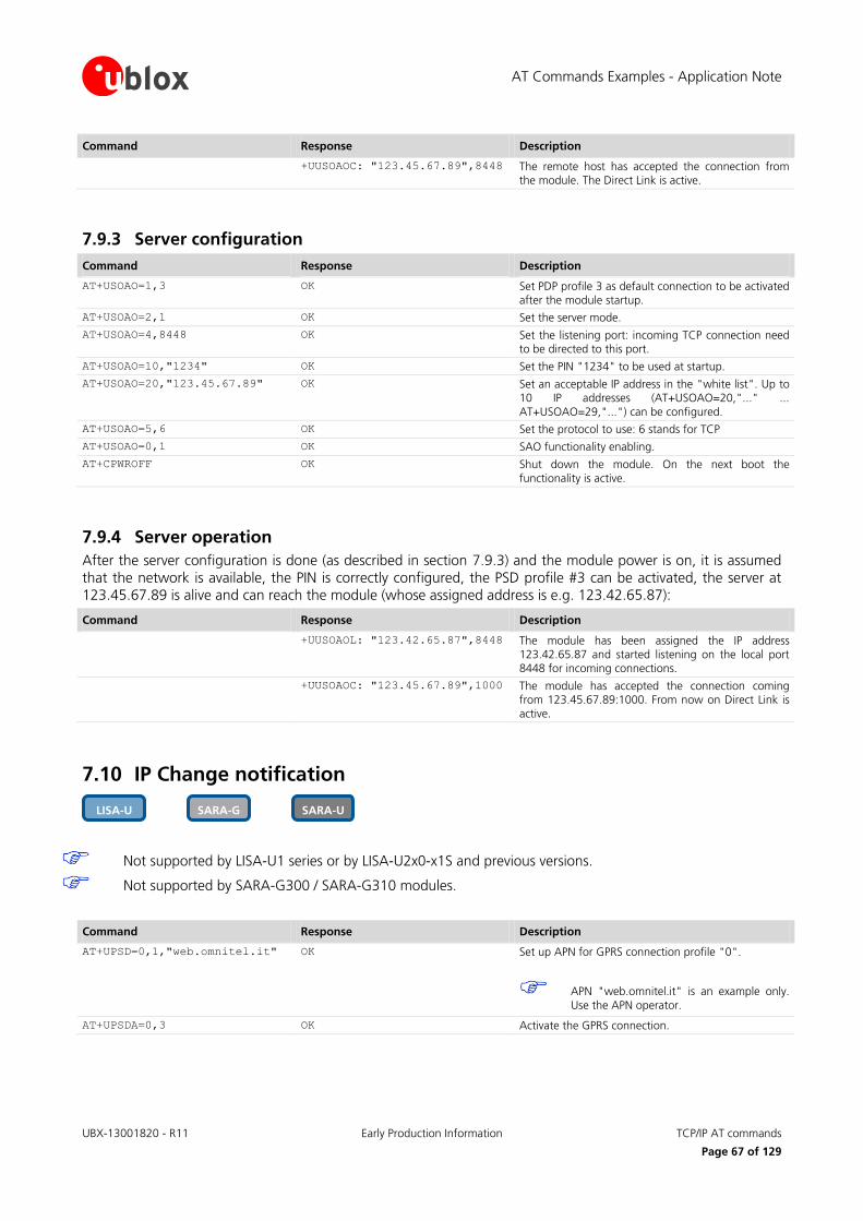
AT Commands Examples - Application Note
UBX-13001820 - R11 Early Production Information TCP/IP AT commands
Page 67 of 129
Command Response Description
+UUSOAOC: "123.45.67.89",8448 The remote host has accepted the connection from the module. The Direct Link is active.
7.9.3 Server configuration
Command Response Description
AT+USOAO=1,3 OK Set PDP profile 3 as default connection to be activated after the module startup.
AT+USOAO=2,1 OK Set the server mode.
AT+USOAO=4,8448 OK Set the listening port: incoming TCP connection need to be directed to this port.
AT+USOAO=10,"1234" OK Set the PIN "1234" to be used at startup.
AT+USOAO=20,"123.45.67.89" OK Set an acceptable IP address in the "white list". Up to 10 IP addresses (AT+USOAO=20,"..." ...
AT+USOAO=29,"...") can be configured.
AT+USOAO=5,6 OK Set the protocol to use: 6 stands for TCP
AT+USOAO=0,1 OK SAO functionality enabling.
AT+CPWROFF OK Shut down the module. On the next boot the
functionality is active.
7.9.4 Server operation
After the server configuration is done (as described in section 7.9.3) and the module power is on, it is assumed that the network is available, the PIN is correctly configured, the PSD profile #3 can be activated, the server at 123.45.67.89 is alive and can reach the module (whose assigned address is e.g. 123.42.65.87):
Command Response Description
+UUSOAOL: "123.42.65.87",8448 The module has been assigned the IP address 123.42.65.87 and started listening on the local port 8448 for incoming connections.
+UUSOAOC: "123.45.67.89",1000 The module has accepted the connection coming from 123.45.67.89:1000. From now on Direct Link is active.
7.10 IP Change notification
Not supported by LISA-U1 series or by LISA-U2x0-x1S and previous versions.
Not supported by SARA-G300 / SARA-G310 modules.
Command Response Description
AT+UPSD=0,1,"web.omnitel.it" OK Set up APN for GPRS connection profile "0".
APN "web.omnitel.it" is an example only.
Use the APN operator.
AT+UPSDA=0,3 OK Activate the GPRS connection.
SARA-U SARA-G LISA-U
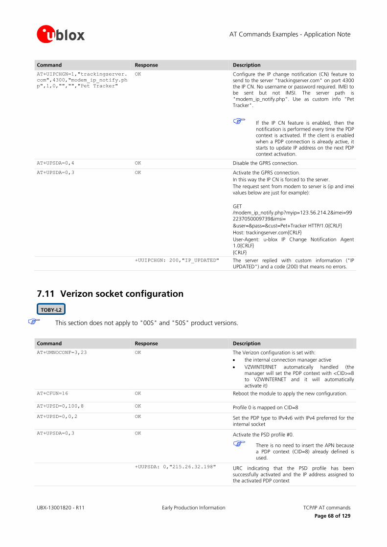
AT Commands Examples - Application Note
UBX-13001820 - R11 Early Production Information TCP/IP AT commands
Page 68 of 129
Command Response Description
AT+UIPCHGN=1,"trackingserver.
com",4300,"modem_ip_notify.ph
p",1,0,"","","Pet Tracker"
OK Configure the IP change notification (CN) feature to send to the server "trackingserver.com" on port 4300
the IP CN. No username or password required. IMEI to be sent but not IMSI. The server path is
"modem_ip_notify.php". Use as custom info "Pet Tracker".
If the IP CN feature is enabled, then the
notification is performed every time the PDP context is activated. If the client is enabled
when a PDP connection is already active, it starts to update IP address on the next PDP context activation.
AT+UPSDA=0,4 OK Disable the GPRS connection.
AT+UPSDA=0,3 OK Activate the GPRS connection.
In this way the IP CN is forced to the server.
The request sent from modem to server is (ip and imei
values below are just for example):
GET
/modem_ip_notify.php?myip=123.56.214.2&imei=992237050009739&imsi=
&user=&pass=&cust=Pet+Tracker HTTP/1.0{CRLF}
Host: trackingserver.com{CRLF}
User-Agent: u-blox IP Change Notification Agent
1.0{CRLF}
{CRLF}
+UUIPCHGN: 200,"IP_UPDATED" The server replied with custom information ("IP UPDATED") and a code (200) that means no errors.
7.11 Verizon socket configuration
This section does not apply to "00S" and "50S" product versions.
Command Response Description
AT+UMNOCONF=3,23 OK The Verizon configuration is set with:
the internal connection manager active
VZWINTERNET automatically handled (the manager will set the PDP context with <CID>=8
to VZWINTERNET and it will automatically activate it)
AT+CFUN=16 OK Reboot the module to apply the new configuration.
AT+UPSD=0,100,8 OK Profile 0 is mapped on CID=8
AT+UPSD=0,0,2 OK Set the PDP type to IPv4v6 with IPv4 preferred for the
internal socket
AT+UPSDA=0,3 OK Activate the PSD profile #0.
There is no need to insert the APN because a PDP context (CID=8) already defined is used.
+UUPSDA: 0,"215.26.32.198" URC indicating that the PSD profile has been
successfully activated and the IP address assigned to the activated PDP context
TOBY-L2

AT Commands Examples - Application Note
UBX-13001820 - R11 Early Production Information TCP/IP AT commands
Page 69 of 129
7.12 AT&T socket configuration
This section does not apply to "00S" and "50S" product versions.
Command Response Description
AT+UMNOCONF=2 OK The AT&T configuration is set: IMS service is disabled, Verizon connection manager is disabled, 3G bands are enabled, all supported 4G bands are enabled, HSDPA
Category set to 14.
AT+CFUN=16 OK The module is rebooted to apply the new configuration.
AT+COPS? +COPS: 0,0,"AT&T",7
OK
The module is registered on 4G network.
AT+UPSD=0,100,4 OK Suppose that the default bearer is CID=4 and it is not possible to activate another context, so profile 0 is
mapped on CID=4
AT+UPSD=0,0,0 OK Set the PDP type to IPv4 for the internal socket (AT&T wants IPv4)
AT+UPSDA=0,3 OK Activate the PSD profile #0.
There is no need to insert the APN because a PDP context (CID=4) already defined is
used.
+UUPSDA: 0,"215.26.32.198" URC indicating that the PSD profile has been successfully activated and the IP address assigned to
the activated PDP context
AT+CFUN=16 OK Reboot the module.
AT+COPS? +COPS: 0,0,"AT&T",2
OK
The module is registered on 3G network.
AT+UPSD=0,1,"<AT&T_apn>" OK There is no default bearer already activated, the user
shall define the PSD profile’s APN
AT+UPSDA=0,3 OK Activate the PSD profile #0.
The PSD context is activated on CID=8.
+UUPSDA: 0,"215.26.32.198" URC indicating that the PSD profile has been successfully activated and the IP address assigned to
the activated PDP context
TOBY-L2

AT Commands Examples - Application Note
UBX-13001820 - R11 Early Production Information UDP/IP AT commands
Page 70 of 129
8 UDP/IP AT commands
Not supported by SARA-G300 / SARA-G310 modules.
8.1 Socket write (+USOST)
Command Response Description
AT+USOCR=17 +USOCR: 0
OK
UDP socket creation. In this example Socket #0 is created.
The information text response returns the new socket
identifier (in this example #0). If a new socket is created, a new socket identifier will be returned.
AT+USOCR=17,12000 +USOCR: 0,12000
OK
The local port to be used for data sending can be configured during UDP socket creation.
In this example Socket #0 is created and bound with port 12000. Data written on socket #0 will be sent
from this specific port.
AT+UDNSRN=0,"ftp.u-blox.com" +UDNSRN: "195.34.89.241"
OK
DNS resolution of the URL "ftp.u-blox.com".
AT+USOST=0,"195.34.89.241",21
,2
@ Request to write 2 bytes of data into socket #0 specifying IP address and UDP port of the remote host UDP packet has to be sent to. Wait for "@" symbol
indicating the data prompt is now open (AT commands are not allowed in data prompt).
12 +USOST: 0,2
OK
Write data. After the last data byte is written, the prompt is closed.
It is not allowed to write fewer bytes than previously specified with AT+USOST
command.
If more bytes are written with respect to the threshold, the remaining bytes will be
truncated.
The interface is blocked until all bytes are written.
The final result code is returned. This means the data
is sent to lower level of protocol stack. This is not an acknowledgment, UDP is a connectionless protocol.
8.2 Socket read (+USORF)
Command Response Description
+UUSORD: 0,2 A UDP packet with 2 data bytes has been received.
AT+USORF=0,2 +USORF: 0,"195.34.89.241",21,
2,"12"
OK
Read data.
The information text response indicates:
Read socket identifier
Remote IP address
Remote UDP port
Number of read data bytes
Read data bytes (between quotation marks)
+UUSORD: 0,20 UDP packet with 20 data bytes has been received from remote server.
SARA-U SARA-G LISA-U LEON-G

AT Commands Examples - Application Note
UBX-13001820 - R11 Early Production Information UDP/IP AT commands
Page 71 of 129
Command Response Description
AT+USORF=0,10 +USORF: 0,"195.34.89.241",21,
2,"1234567890"
OK
+UUSORD: 0,10
Read 10 data bytes. +UUSORD URC indicates that 10 bytes are still unread.
Remote host sends a UDP packet with 20 data bytes.
AT+USORF=0,10 +USORF: 0,"195.34.89.241",21,
2,"1234567890"
OK
+UUSORD: 0,20
Read the remaining 10 data bytes of the previous packet. URC indicates 20 data bytes have been
received and are still stored in the socket buffer.
After the first URC has been returned, a second URC is returned (only after a
reading operation) indicating:
If a reading operation of a packet is not finished
it will provide the remaining data of the specific packet
Otherwise it will provide the number of data
bytes of packets stored in the socket buffer
For UDP it is highly recommended to use AT commands +USOST and +USORF instead of +USOCO, +USOWR and +USORD.
8.3 Socket write (+USOWR)
Command Response Description
AT+USOCR=17 +USOCR: 0
OK
UDP socket creation. In this example Socket #0 is
created.
The information text response returns the new socket identifier (in this example #0). If a new socket is
created (without closing the already existent), a new socket identifier will be returned.
AT+USOCR=17,12000 +USOCR: 0,12000
OK
The local port to be used while sending data can be configured during UDP socket creation.
In this example Socket #0 is created and bound with port 12000. Data written on socket #0 will be sent
from this specific port.
AT+UDNSRN=0,"ftp.u-blox.com" +UDNSRN: "195.34.89.241"
OK
DNS resolution of the URL "ftp.u-blox.com".
AT+USOCO=0,"195.34.89.241",21 OK Specify IP address of the remote server and TCP port where UDP packets have to be sent.
UDP is a connectionless protocol, reception of
UDP packets is not guaranteed, +USOCO does not establish a connection.
Socket is now ready for data sending to the remote server or for receiving data from the remote server.
AT+USOWR=0,2 @ Request to write 2 bytes of data into socket #0.Wait for "@" symbol indicating the data prompt is now open (AT commands are not allowed in data prompt).
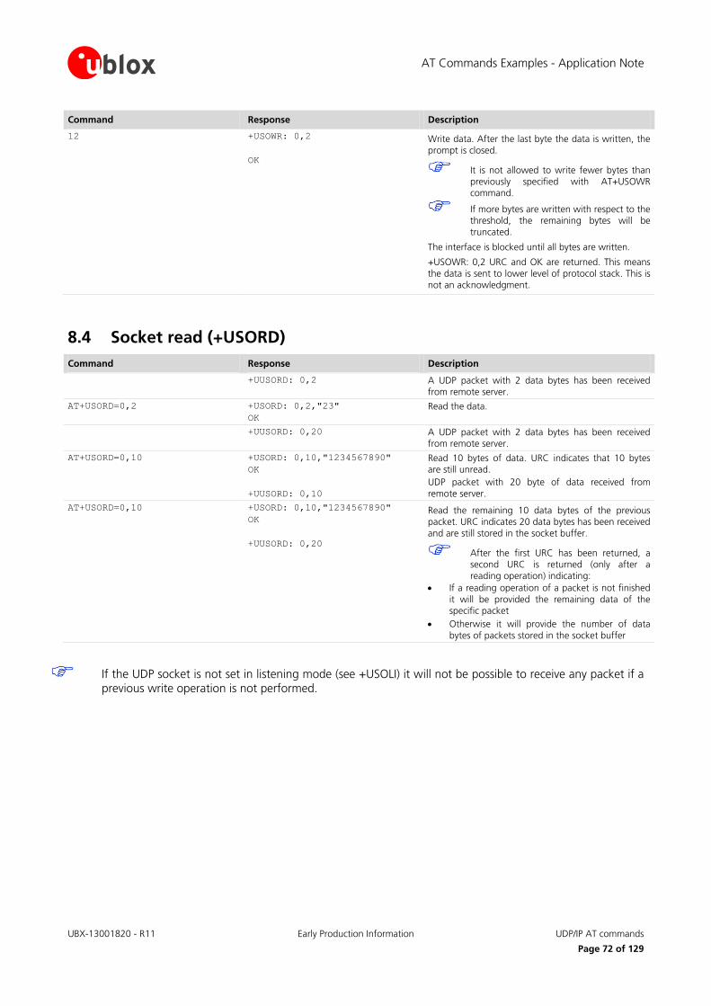
AT Commands Examples - Application Note
UBX-13001820 - R11 Early Production Information UDP/IP AT commands
Page 72 of 129
Command Response Description
12 +USOWR: 0,2
OK
Write data. After the last byte the data is written, the prompt is closed.
It is not allowed to write fewer bytes than previously specified with AT+USOWR command.
If more bytes are written with respect to the threshold, the remaining bytes will be truncated.
The interface is blocked until all bytes are written.
+USOWR: 0,2 URC and OK are returned. This means
the data is sent to lower level of protocol stack. This is not an acknowledgment.
8.4 Socket read (+USORD)
Command Response Description
+UUSORD: 0,2 A UDP packet with 2 data bytes has been received from remote server.
AT+USORD=0,2 +USORD: 0,2,"23"
OK
Read the data.
+UUSORD: 0,20 A UDP packet with 2 data bytes has been received from remote server.
AT+USORD=0,10 +USORD: 0,10,"1234567890"
OK
+UUSORD: 0,10
Read 10 bytes of data. URC indicates that 10 bytes are still unread.
UDP packet with 20 byte of data received from
remote server.
AT+USORD=0,10 +USORD: 0,10,"1234567890"
OK
+UUSORD: 0,20
Read the remaining 10 data bytes of the previous packet. URC indicates 20 data bytes has been received
and are still stored in the socket buffer.
After the first URC has been returned, a second URC is returned (only after a
reading operation) indicating:
If a reading operation of a packet is not finished
it will be provided the remaining data of the specific packet
Otherwise it will provide the number of data
bytes of packets stored in the socket buffer
If the UDP socket is not set in listening mode (see +USOLI) it will not be possible to receive any packet if a previous write operation is not performed.

AT Commands Examples - Application Note
UBX-13001820 - R11 Early Production Information FTP AT commands
Page 73 of 129
9 FTP AT commands
Not supported by SARA-G300 / SARA-G310 modules.
Make sure to follow the steps in "GPRS connection" (section 5) before using the AT commands in this section.
Command Response Description
AT+UFTP=1,"ftp.u-blox.com"
AT+UFTP=2,"anonymous"
AT+UFTP=3,"[email protected]
m"
AT+UFTP=6,0
OK
OK
OK
OK
Parameter configuration for FTP server connection.
These parameters will be set:
FTP server hostname
FTP username
FTP password
FTP connection mode (ACTIVE connection)
AT+UDNSRN=0,"ftp.u-blox.com" +UDNSRN: "195.34.89.241"
OK
Hostname resolution.
Connect to the server and manage the FTP connection using the +UFTPC command. Let’s start connecting to the server.
AT+UFTPC=1 OK
+UUFTPCR: 1,1 The +UUFTPCR URC provides the FTP
command result (the last parameter provides the result, 1 if is successfully
performed).
AT+UFTPC=13 OK
+UUFTPCD: 13,194,"-rw-r--r--
1 ftp ftp 1037
Aug 5 09:45 dat_000
-rw-r--r-- 1 ftp ftp
21041 Aug 5 09:12 data.zip
-rw-r--r-- 1 ftp ftp
12 Aug 5 09:42 xlog.zip
"
+UUFTPCR: 13,1
Request the file list on the server.
AT+UFTPC=10,"uploads" OK
+UUFTPCR: 10,1
Directory creation on the FTP server.
AT+UFTPC=13 OK
+UUFTPCD: 13,258,"-rw-r--r--
1 ftp ftp 1037
Aug 5 09:45 dat_000
-rw-r--r-- 1 ftp ftp
21041 Aug 5 09:12 data.zip
drwxr-xr-x 2 ftp ftp
4096 Aug 5 09:48 uploads
-rw-r--r-- 1 ftp ftp
12 Aug 5 09:42 xlog.zip
"
+UUFTPCR: 13,1
Request again the file list.
SARA-U SARA-G LISA-U LEON-G

AT Commands Examples - Application Note
UBX-13001820 - R11 Early Production Information FTP AT commands
Page 74 of 129
Command Response Description
Change directory to directory name "uploads".
AT+UFTPC=8,"uploads" OK
+UUFTPCR: 8,1
Use AT+UFTPC=8,".." to return back in the parent directory.
AT+UFTPC=5,"gps_positions","g
ps_positions"
OK
+UUFTPCR: 5,1
Upload a file from the module to FTP server from local file system of the module (in this example filename
"gps_positions").
AT+UFTPC=5,"gps_positions","g
ps_positions",250
OK
+UUFTPCR: 5,1
Restart upload file from the module to FTP server from local module file system (in this example filename
"gps_positions"), starting from byte 250.
The FTP server should support the REST
command to support these functionalities. The server should write the file starting from byte indicated.
Restart feature is only supported by LISA-U2x0-02S and subsequent versions and on SARA-U series.
AT+UFTPC=13 OK
+UUFTPCD: 13,70,"-rw-r--r--
1 ftp ftp 176673
Aug 5 10:03 gps_positions"
+UUFTPCR: 13,1
File list request.
AT+UFTPC=8,".." OK
+UUFTPCR: 8,1
Return to the parent directory.
AT+UFTPC=4,"data.zip","data.z
ip"
OK
+UUFTPCR: 4,1
Download a file from the FTP server to the local file system of the module.
AT+UFTPC=4,"data.zip","data.z
ip",1
OK
+UUFTPCR: 4,1
Restart the file download from the FTP server to the local module file system from the latest byte saved on file system (this is automatically calculated). The data
received is written after latest byte available on file system.
Restart feature is only supported by
LISA-U2x0-02S and subsequent versions and on SARA-U series.
AT+UFTPC=0 OK
+UUFTPCR: 0,1
FTP server disconnection.
AT+UPSDA=0,4 OK GPRS connection detachment with the +UPSDA command.
Only the specified profile will be deactivated.
To list and view all files stored in the cellular module file system, see section 18.

AT Commands Examples - Application Note
UBX-13001820 - R11 Early Production Information FTP AT commands
Page 75 of 129
9.1 Direct link
9.1.1 Retrieve a file from FTP server
Command Response Description
AT+UFTP=1,"ftp.u-blox.com"
AT+UFTP=2,"anonymous"
AT+UFTP=3,"[email protected]
m"
AT+UFTP=6,0
OK
OK
OK
OK
Parameters configuration for the FTP server connection.
These parameters will be set:
FTP server hostname
FTP username
FTP password
FTP connection mode (ACTIVE connection)
AT+UDNSRN=0,"ftp.u-blox.com" +UDNSRN: "195.34.89.241"
OK
Hostname resolution.
Connect to the server and manage the FTP connection using the +UFTPC command.
AT+UFTPC=1 OK
+UUFTPCR: 1,1
+UUFTPCR URC is returned when the connection is established.
AT+UFTPC=6,"file_to_retrieve" CONNECT Send to FTP server a RETRIEVE file request for
file_to_retrieve.
CONNECT result code means direct link mode is activated: the data received from FTP connection will
be redirected to the serial port.
AT+UFTPC=6,"file_to_retrieve"
,250
CONNECT Restart a RETRIEVE file request for
file_to_retrieve file from byte 250.
CONNECT result code means the direct link mode
activation: the data received from FTP connection is redirected to the serial port.
The data reception begins with the byte indicated.
Restart feature is only supported by LISA-U2x0-02S and subsequent versions
and on SARA-U series.
+++ DISCONNECT
OK
+UUFTPCR: 6,1
WARNING: When the file has entirely been
retrieved the module does not exit from direct link mode. It is necessary to manually exit using
"+++" escape sequence.
+UUFTPCR URC notifies how the retrieve operation
has been concluded (1 means success).
The "DISCONNECT" result code is not supported by LEON-G100-03S /
LEON-G200-03S and previous versions.

AT Commands Examples - Application Note
UBX-13001820 - R11 Early Production Information FTP AT commands
Page 76 of 129
9.1.2 Aborting retrieve file request
Command Response Description
+++ DISCONNECT
OK
+UUFTPCR: 6,0
If entering "+++" escape sequence before the requested file has been entirely retrieved from FTP server, module exits from direct link and +UUFTPCR
URC notifies that retrieve operation has not been concluded successfully (0 means fail).
The "DISCONNECT" result code is not supported by LEON-G100-03S / LEON-G200-03S and previous versions.
9.1.3 Store a file on FTP server
Command Response Description
AT+UFTP=1,"ftp.u-blox.com"
AT+UFTP=2,"anonymous"
AT+UFTP=3,"[email protected]
m"
AT+UFTP=6,0
OK
OK
OK
OK
Parameter configuration for FTP server connection
These parameters will be set:
FTP server hostname
FTP username
FTP password
FTP connection mode (ACTIVE connection)
AT+UDNSRN=0,"ftp.u-blox.com" +UDNSRN: "195.34.89.241"
OK
Hostname resolution.
Connect to the server and manage the FTP.
Connection using the +UFTPC command. Let’s start connecting to the server.
AT+UFTPC=1 OK
+UUFTPCR: 1,1
+UUFTPCR URC is returned when the
connection is established.
AT+UFTPC=7,"file_to_store" CONNECT Send to FTP server a STORE file request for
file_to_store.
CONNECT result code means direct link mode is activated: the data sent through the serial port will be
redirected to FTP server through the FTP connection.
AT+UFTPC=7,"file_to_store",25
0
CONNECT Restart STORE file request for file_to_store from
byte 250.
CONNECT result code means the direct link mode
activation: the data sent through the serial port is redirected to FTP server through the FTP connection.
The data is written on FTP server starting from byte
indicated.
FTP Server should support REST command to support this functionality.
Restart feature is only supported by LISA-U2x0-02S and subsequent versions and on SARA-U series.

AT Commands Examples - Application Note
UBX-13001820 - R11 Early Production Information FTP AT commands
Page 77 of 129
Command Response Description
+++ DISCONNECT
OK
When data upload is concluded use "+++" escape sequence for exiting from direct link mode.
+UUFTPCR: 7,1 The +UUFTPCR URC notifies if STORE operation has been concluded successfully.
9.1.4 About "+++" escape sequence usage
To switch from data mode to command mode a proper escape sequence shall be sent by the application to the module. The application can configure the escape sequence by means of the following commands:
ATS2: this command sets the character used as the escape character (default is "+")
ATS12: this command sets the escape prompt delay (TEPD
) timer (default is 1 s)
For more details on the AT commands, see the u-blox AT Commands Manual [1].
The escape sequence must follow certain timing constraints to be distinguished from generic data.
T0 T1 T2 T3
data + ++AT command
UART RX
time
T0 > TEPD
: there must be at least TEPD
seconds after the last data byte and the first escape character
T1 < TEPD
: the second escape character must be sent within TEPD
seconds after the first escape character
T2 < TEPD
: the third escape character must be sent within TEPD
seconds after the second escape character
T3 > TEPD
: There must be at least TEPD
seconds after the last escape character and the first AT command
9.2 Using secure option
Command Response Description
Parameters configuration for the FTP server connection in secure mode.
These parameters are set:
AT+UFTP=0,"123.213.132.231" OK FTP server address
AT+UFTP=2,"myname" OK FTP username
AT+UFTP=3,"mypwd" OK FTP password
AT+UFTP=8,1 OK FTP SSL encryption enabled
AT+UFTPC=1 FTP login.
Connect to the server and manage the FTP connection
using the +UFTPC command. Let’s start connecting to the server.
OK
+UUFTPCR: 1,1
The +UUFTPCR URC provides the FTP command result (the second parameter provides the result, 1 if is successfully
performed).
Some operators may not accept a secure FTP connection:
SARA-U LISA-U
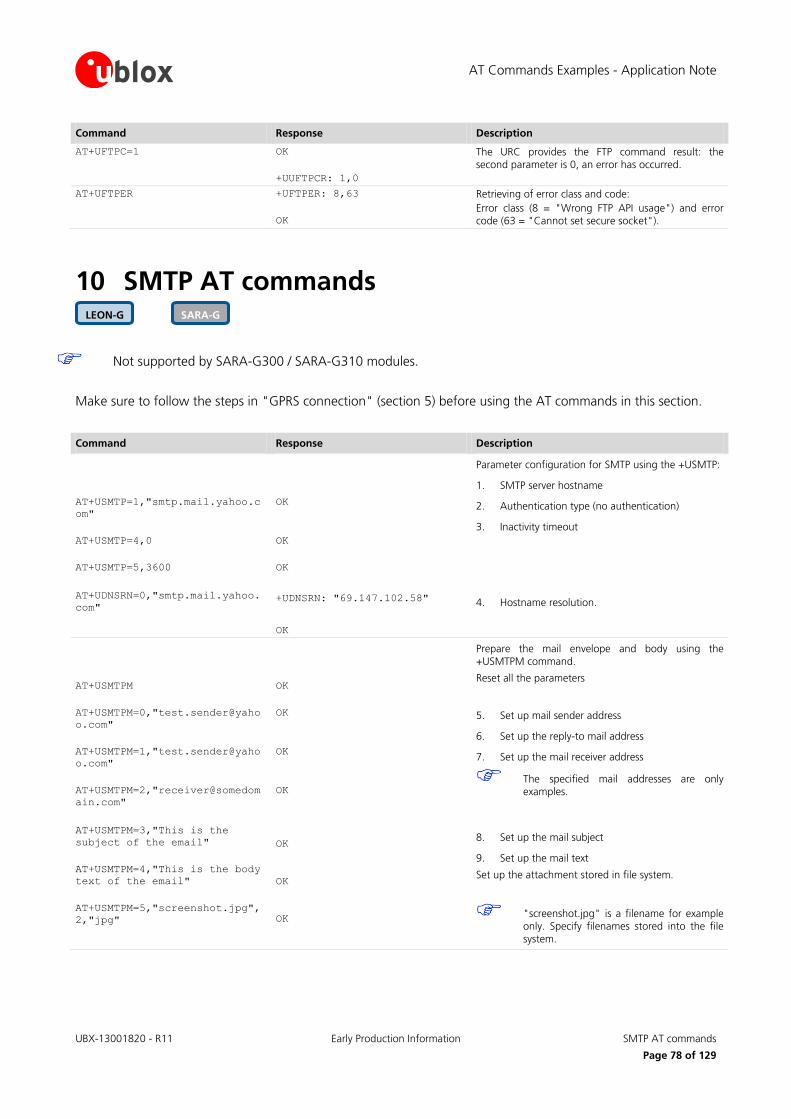
AT Commands Examples - Application Note
UBX-13001820 - R11 Early Production Information SMTP AT commands
Page 78 of 129
Command Response Description
AT+UFTPC=1 OK
+UUFTPCR: 1,0
The URC provides the FTP command result: the second parameter is 0, an error has occurred.
AT+UFTPER +UFTPER: 8,63
OK
Retrieving of error class and code:
Error class (8 = "Wrong FTP API usage") and error code (63 = "Cannot set secure socket").
10 SMTP AT commands
Not supported by SARA-G300 / SARA-G310 modules.
Make sure to follow the steps in "GPRS connection" (section 5) before using the AT commands in this section.
Command Response Description
AT+USMTP=1,"smtp.mail.yahoo.c
om"
AT+USMTP=4,0
AT+USMTP=5,3600
OK
OK
OK
Parameter configuration for SMTP using the +USMTP:
1. SMTP server hostname
2. Authentication type (no authentication)
3. Inactivity timeout
AT+UDNSRN=0,"smtp.mail.yahoo.
com" +UDNSRN: "69.147.102.58"
OK
4. Hostname resolution.
AT+USMTPM
AT+USMTPM=0,"test.sender@yaho
o.com"
AT+USMTPM=1,"test.sender@yaho
o.com"
AT+USMTPM=2,"receiver@somedom
ain.com"
OK
OK
OK
OK
Prepare the mail envelope and body using the +USMTPM command.
Reset all the parameters
5. Set up mail sender address
6. Set up the reply-to mail address
7. Set up the mail receiver address
The specified mail addresses are only examples.
AT+USMTPM=3,"This is the
subject of the email"
AT+USMTPM=4,"This is the body
text of the email"
AT+USMTPM=5,"screenshot.jpg",
2,"jpg"
OK
OK
OK
8. Set up the mail subject
9. Set up the mail text
Set up the attachment stored in file system.
"screenshot.jpg" is a filename for example only. Specify filenames stored into the file system.
SARA-G LEON-G
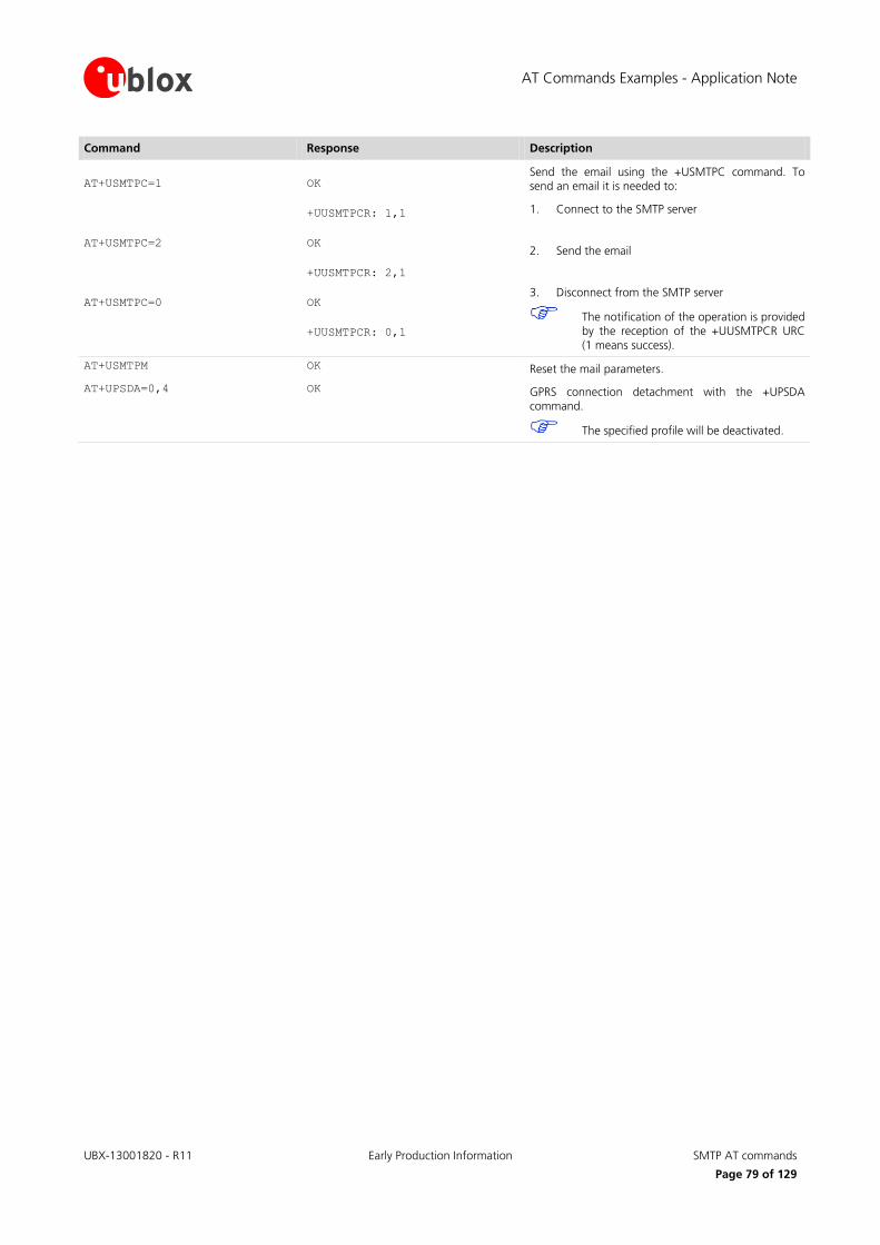
AT Commands Examples - Application Note
UBX-13001820 - R11 Early Production Information SMTP AT commands
Page 79 of 129
Command Response Description
AT+USMTPC=1
AT+USMTPC=2
AT+USMTPC=0
OK
+UUSMTPCR: 1,1
OK
+UUSMTPCR: 2,1
OK
+UUSMTPCR: 0,1
Send the email using the +USMTPC command. To send an email it is needed to:
1. Connect to the SMTP server
2. Send the email
3. Disconnect from the SMTP server
The notification of the operation is provided by the reception of the +UUSMTPCR URC
(1 means success).
AT+USMTPM OK Reset the mail parameters.
AT+UPSDA=0,4 OK GPRS connection detachment with the +UPSDA command.
The specified profile will be deactivated.

AT Commands Examples - Application Note
UBX-13001820 - R11 Early Production Information ODIS implementation
Page 80 of 129
11 ODIS implementation
Supported by SARA-U201 modules only.
u-blox cellular modules contain an OMA-DM client complying with the OMA-DM standard 1.2.1 [14]and customized for the AT&T requirements regarding ODIS (OMA-DM IMEI Sync) and FW update notification [15].
AT&T requires all radio module integrators (OEMs) to support ODIS or else to assign a unique TAC on a unique device basis, as defined in the PTCRB PPMD rules. As a manual alternative, all the devices that do not implement ODIS or are using a module that does not support ODIS must provide AT&T with a data file which maps IMEIs to host device information. This data file should be a .csv formatted text file reporting the following info: host manufacturer name, host software version, host model, IMEI and host device Plasma ID (assigned by AT&T). Data must be provided to AT&T on a recurring three-month basis beginning at the time AT&T approval is granted.
This chapter instructs the users on the ODIS functionality implementation based on the module OMA-DM client.
It is the user’s responsibility to properly configure the ODIS parameters into the cellular module according to the host device details.
It is recommended to populate the ODIS nodes during the host device production process. Once populated, the AT&T OMA-DM server may query the device at any time to read the content of the nodes.
The OMA-DM client uses the internal PDP context with pre-defined “phone” APN. The APN may be reconfigured remotely via OMA-DM protocol. The context is activated whenever needed (and deactivated when not needed) by the OMA-DM client:
o With the +UOMADM=1 command o With the +UOMADMALERT command o When a correct OMA-DM WAP Push is received.
11.1 OMA-DM client initialization
At the module power-on, the OMA-DM functionality is automatically enabled and remains in an idle state with no communications with the OMA-DM server until one of the following events occurs:
Network initiated: the module receives a notification (WAP push) from the OMA-DM server. This procedure is completely automatic and requires no actions from the host application processor.
Device initiated: the module initiates a connection with the OMA-DM server to update the ODIS nodes (see section 11.2). In this case the OMA-DM client must be initialized with the +UOMADM AT command.
Command Response Description
AT+COPS? +COPS: 0,0,"AT&T",2
OK
Verify the module is registered under AT&T network.
AT+CCLK="16/09/21,17:24:00+00
"
OK Set the correct date / time.
AT+UOMADM=1 OK Initialize the OMA-DM client.
After initialization, the module will attempt to connect with the OMA-DM server if
available.
It is not required to stop the connection with the OMA-DM server: the module OMA-DM client will automatically close it when all pending transactions are completed.
In order to be activated, an OMA-DM session requires module registration under the AT&T network.
The module does not notify the user in case the OMA-DM connection with the server is unavailable.
SARA-U
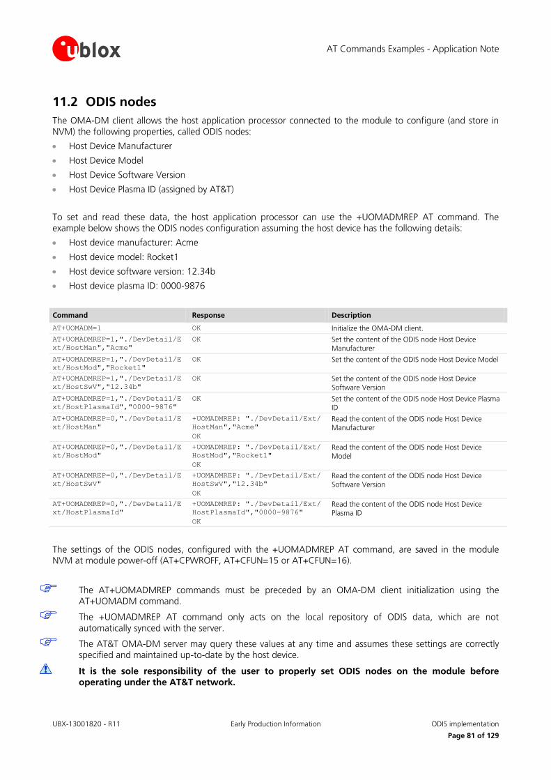
AT Commands Examples - Application Note
UBX-13001820 - R11 Early Production Information ODIS implementation
Page 81 of 129
11.2 ODIS nodes
The OMA-DM client allows the host application processor connected to the module to configure (and store in NVM) the following properties, called ODIS nodes:
Host Device Manufacturer
Host Device Model
Host Device Software Version
Host Device Plasma ID (assigned by AT&T)
To set and read these data, the host application processor can use the +UOMADMREP AT command. The example below shows the ODIS nodes configuration assuming the host device has the following details:
Host device manufacturer: Acme
Host device model: Rocket1
Host device software version: 12.34b
Host device plasma ID: 0000-9876
Command Response Description
AT+UOMADM=1 OK Initialize the OMA-DM client.
AT+UOMADMREP=1,"./DevDetail/E
xt/HostMan","Acme"
OK Set the content of the ODIS node Host Device Manufacturer
AT+UOMADMREP=1,"./DevDetail/E
xt/HostMod","Rocket1"
OK Set the content of the ODIS node Host Device Model
AT+UOMADMREP=1,"./DevDetail/E
xt/HostSwV","12.34b"
OK Set the content of the ODIS node Host Device Software Version
AT+UOMADMREP=1,"./DevDetail/E
xt/HostPlasmaId","0000-9876"
OK Set the content of the ODIS node Host Device Plasma ID
AT+UOMADMREP=0,"./DevDetail/E
xt/HostMan"
+UOMADMREP: "./DevDetail/Ext/
HostMan","Acme"
OK
Read the content of the ODIS node Host Device Manufacturer
AT+UOMADMREP=0,"./DevDetail/E
xt/HostMod"
+UOMADMREP: "./DevDetail/Ext/
HostMod","Rocket1"
OK
Read the content of the ODIS node Host Device Model
AT+UOMADMREP=0,"./DevDetail/E
xt/HostSwV"
+UOMADMREP: "./DevDetail/Ext/
HostSwV","12.34b"
OK
Read the content of the ODIS node Host Device
Software Version
AT+UOMADMREP=0,"./DevDetail/E
xt/HostPlasmaId"
+UOMADMREP: "./DevDetail/Ext/
HostPlasmaId","0000-9876"
OK
Read the content of the ODIS node Host Device Plasma ID
The settings of the ODIS nodes, configured with the +UOMADMREP AT command, are saved in the module NVM at module power-off (AT+CPWROFF, AT+CFUN=15 or AT+CFUN=16).
The AT+UOMADMREP commands must be preceded by an OMA-DM client initialization using the AT+UOMADM command.
The +UOMADMREP AT command only acts on the local repository of ODIS data, which are not automatically synced with the server.
The AT&T OMA-DM server may query these values at any time and assumes these settings are correctly specified and maintained up-to-date by the host device.
It is the sole responsibility of the user to properly set ODIS nodes on the module before operating under the AT&T network.

AT Commands Examples - Application Note
UBX-13001820 - R11 Early Production Information ODIS implementation
Page 82 of 129
In case of any subsequent change in the previously defined ODIS nodes (e.g. after a FW update of the application processor), the host device might notify the OMA-DM server using the AT+UOMADMALERT command.
Command Response Description
AT+UOMADM=1 OK Initialize the OMA-DM client.
AT+UOMADMREP=1,"./DevDetail/E
xt/HostSwV","12.57z"
OK The ODIS node Host Device Software Version is
updated.
AT+UOMADMALERT=1,"
","org.openmobilealliance.dm.
firmwareupdate.devicerequest"
,"./DevDetail/Ext/HostSwV"
OK The OMA-DM server is alerted that the content of the ODIS node Host Device Software Version has been
changed.
11.3 Module FW update notification
The AT&T requirement <CDR-DVM-1533> [15] mandates that a FW update on the cellular module must be notified to the AT&T OMA-DM server.
The module FW upgrade may cause a change an update in the following nodes:
Module FW version
Module SW version
International Mobile station Equipment Identity and Software Version number (IMEISV)
The host application processor has no control over the previous nodes but must notify the AT&T OMA-DM server about the changes occurred.
See the AT Commands Manual [1] and the Firmware Update Application Note [13] for more details about the FW update procedure of the cellular module.
It is the responsibility of the host application processor to notify the OMA-DM server after the module FW update process has been completed.
After the module FW update completion, execute the following command sequence to notify the AT&T OMA-DM server about the changes introduced.
Command Response Description
AT+UOMADMALERT=1,"","org.open
mobilealliance.dm.firmwareupd
ate.devicerequest","./DevDeta
il/FwV"
OK Alert the OMA-DM server that the content of the node Module FW Version has been changed.
AT+UOMADMALERT=1,"","org.open
mobilealliance.dm.firmwareupd
ate.devicerequest","./DevDeta
il/SwV"
OK Alert the OMA-DM server that the content of the node Module SW Version has been changed.
AT+UOMADMALERT=1,"","org.open
mobilealliance.dm.firmwareupd
ate.devicerequest","./DevDeta
il/Ext/IMEISV"
OK Alert the OMA-DM server that the content of the
node IMEISV has been changed.

AT Commands Examples - Application Note
UBX-13001820 - R11 Early Production Information ODIS implementation
Page 83 of 129
11.4 OMA-DM client activity reporting
It is often useful to get an indication on the activity of the OMA-DM client, which can silently connect to a server for remotely-controlled operations.
The +UUOMASTAT URC can be used in this case.
Command Response Description
AT+UOMASTAT=1 OK Enabling the +UUOMASTAT URC.
+UUOMASTAT: 1,0,0 A WAP Push triggering OMA-DM has been received, an OMA-DM session is started
+UUOMASTAT: 1,1,0 The OMA-DM session has completed without errors.
The connection with the server is closed.
This does not imply that the ODIS nodes have been properly written or updated on
the OMA-DM server.
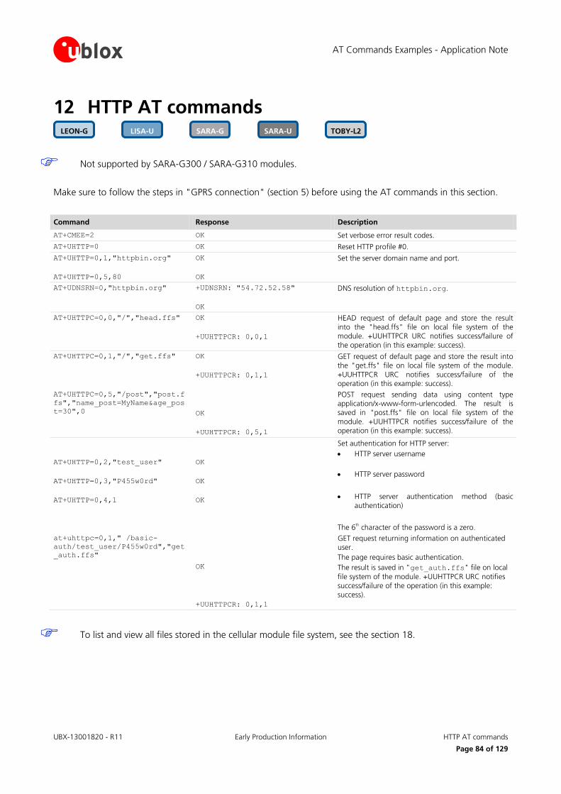
AT Commands Examples - Application Note
UBX-13001820 - R11 Early Production Information HTTP AT commands
Page 84 of 129
12 HTTP AT commands
Not supported by SARA-G300 / SARA-G310 modules.
Make sure to follow the steps in "GPRS connection" (section 5) before using the AT commands in this section.
Command Response Description
AT+CMEE=2 OK Set verbose error result codes.
AT+UHTTP=0 OK Reset HTTP profile #0.
AT+UHTTP=0,1,"httpbin.org"
AT+UHTTP=0,5,80
OK
OK
Set the server domain name and port.
AT+UDNSRN=0,"httpbin.org" +UDNSRN: "54.72.52.58"
OK
DNS resolution of httpbin.org.
AT+UHTTPC=0,0,"/","head.ffs" OK
+UUHTTPCR: 0,0,1
HEAD request of default page and store the result into the "head.ffs" file on local file system of the module. +UUHTTPCR URC notifies success/failure of
the operation (in this example: success).
AT+UHTTPC=0,1,"/","get.ffs" OK
+UUHTTPCR: 0,1,1
GET request of default page and store the result into the "get.ffs" file on local file system of the module.
+UUHTTPCR URC notifies success/failure of the operation (in this example: success).
AT+UHTTPC=0,5,"/post","post.f
fs","name_post=MyName&age_pos
t=30",0
OK
+UUHTTPCR: 0,5,1
POST request sending data using content type application/x-www-form-urlencoded. The result is saved in "post.ffs" file on local file system of the
module. +UUHTTPCR notifies success/failure of the operation (in this example: success).
AT+UHTTP=0,2,"test_user"
AT+UHTTP=0,3,"P455w0rd"
AT+UHTTP=0,4,1
OK
OK
OK
Set authentication for HTTP server:
HTTP server username
HTTP server password
HTTP server authentication method (basic
authentication)
The 6th character of the password is a zero.
at+uhttpc=0,1," /basic-
auth/test_user/P455w0rd","get
_auth.ffs"
OK
+UUHTTPCR: 0,1,1
GET request returning information on authenticated user.
The page requires basic authentication.
The result is saved in "get_auth.ffs" file on local
file system of the module. +UUHTTPCR URC notifies
success/failure of the operation (in this example: success).
To list and view all files stored in the cellular module file system, see the section 18.
TOBY-L2 SARA-U SARA-G LISA-U LEON-G

AT Commands Examples - Application Note
UBX-13001820 - R11 Early Production Information HTTP AT commands
Page 85 of 129
12.1 Using secure option
The enabling of the SSL/TLS protocol provides a secure connection between two entities using TCP sockets for communication (i.e. HTTP/FTP server and HTTP/FTP client).
The security aspects used in the current connection depend on the SSL/TLS configuration and features supported by the communication entities on which basis it is possible to set the server authentication, the client authentication, the data security and integrity.
First of all, it is important to explain the concept of X.509 certificates and the way in which they can be imported in the module for establishing a SSL/TLS connection.
12.1.1 Importing a X.509 certificate
In cryptography, X.509 is an ITU-T standard that specifies the use of certificates, their structure and features.
In detail, they can be defined in the following ways:
DER (Distinguished Encoding Rules): binary format;
PEM (Privacy-Enhanced Mail): base 64 encoding of a DER certificate.
Consequently, different procedures can be identified in the handling of these types by AT+USECMNG command.
12.1.1.1 Example 1: import a root certificate in DER format
In this case it is supposed that a DER certificate has been previously stored in the module file system by downloading it, as an example, from an FTP server by means of AT commands (see the section 9 for details). Then its actual import is carried out as follows.
Command Response Description
AT+CMEE=2 OK Set the verbose error result codes.
AT+ULSTFILE=0 +ULSTFILE: "MyRootCA.der"
OK
List all the files in the file system.
AT+USECMNG=1,0,"MyRootCA","My
RootCA.der"
+USECMNG: 1,0,"MyRootCA","f77
5ab29fb514eb7775eff053c998ef5
"
OK
Import a certificate in DER format from a file stored on file system and save it internally as "MyRootCA".
AT+USECMNG=3 CA,"MyRootCA","IssuerRootCA",
"2022/05/21 04:00:00"
OK
List imported certificates.
12.1.1.2 Example 2: import a root certificate in PEM format
Now it is necessary first to obtain the root certificate in PEM format from the target website and then to import it in the module. These topics are analyzed in detail in the next sections.
Retrieving a root certificate
First of all connect to the desired website by browser: in the example in Figure 23, the u-blox homepage is the target website.
Once the u-blox homepage is loaded in the browser, click on the lock symbol in the address bar of the browser to inspect the website certificate.
TOBY-L2 SARA-U SARA-G LISA-U

AT Commands Examples - Application Note
UBX-13001820 - R11 Early Production Information HTTP AT commands
Page 86 of 129
Figure 23: Click on the lock symbol of the u-blox homepage
Then push the "More Information" button to see the information related to the page.
Figure 24: u-blox page information
Next select the "View Certificate" button.
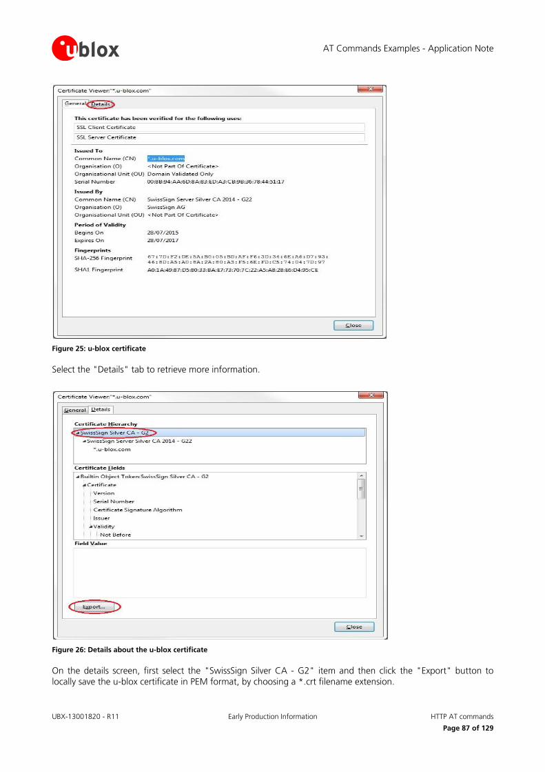
AT Commands Examples - Application Note
UBX-13001820 - R11 Early Production Information HTTP AT commands
Page 87 of 129
Figure 25: u-blox certificate
Select the "Details" tab to retrieve more information.
Figure 26: Details about the u-blox certificate
On the details screen, first select the "SwissSign Silver CA - G2" item and then click the "Export" button to locally save the u-blox certificate in PEM format, by choosing a *.crt filename extension.

AT Commands Examples - Application Note
UBX-13001820 - R11 Early Production Information HTTP AT commands
Page 88 of 129
Later the u-blox certificate can be viewed with a common text editor as follows.
Figure 27: u-blox certificate in PEM format
At this point the user is able to import the reported certificate in the module by a copy and paste operation when the suitable AT command is issued as described in detail in the next section.
Handling a root certificate
Now the user holds a *.crt file containing the u-blox certificate in PEM format so he is able to carry out the import procedure as follows.
Command Response Description
AT+CMEE=2 OK Set the verbose error result codes.
AT+USECMNG=0,0,"u-bloxCA",208
2
> Start the data transfer using the stream of byte
(in this case 2082 is the size in bytes of the certificate).
PEM encoded trusted root
certificate data
+USECMNG: 0,0,"u-bloxCA","e00
6a1c97dcfc9fc0dc0567596d86213
"
OK
Input PEM formatted trusted root certificate data bytes. Output MD5 hash string of the stored trusted
root certificate DER.
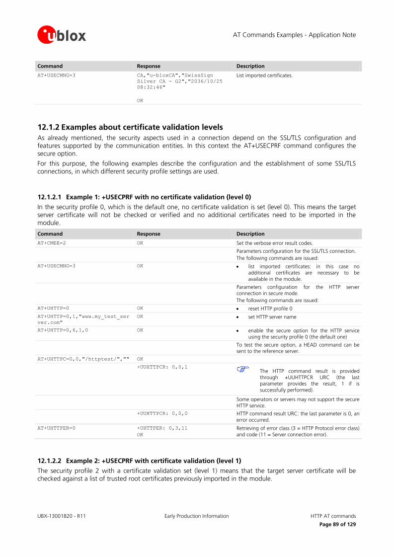
AT Commands Examples - Application Note
UBX-13001820 - R11 Early Production Information HTTP AT commands
Page 89 of 129
Command Response Description
AT+USECMNG=3 CA,"u-bloxCA","SwissSign
Silver CA - G2","2036/10/25
08:32:46"
OK
List imported certificates.
12.1.2 Examples about certificate validation levels
As already mentioned, the security aspects used in a connection depend on the SSL/TLS configuration and features supported by the communication entities. In this context the AT+USECPRF command configures the secure option.
For this purpose, the following examples describe the configuration and the establishment of some SSL/TLS connections, in which different security profile settings are used.
12.1.2.1 Example 1: +USECPRF with no certificate validation (level 0)
In the security profile 0, which is the default one, no certificate validation is set (level 0). This means the target server certificate will not be checked or verified and no additional certificates need to be imported in the module.
Command Response Description
AT+CMEE=2 OK Set the verbose error result codes.
Parameters configuration for the SSL/TLS connection.
The following commands are issued:
AT+USECMNG=3 OK list imported certificates: in this case no additional certificates are necessary to be
available in the module.
Parameters configuration for the HTTP server connection in secure mode.
The following commands are issued:
AT+UHTTP=0 OK reset HTTP profile 0
AT+UHTTP=0,1,"www.my_test_ser
ver.com"
OK set HTTP server name
AT+UHTTP=0,6,1,0 OK enable the secure option for the HTTP service using the security profile 0 (the default one)
To test the secure option, a HEAD command can be sent to the reference server.
AT+UHTTPC=0,0,"/httptest/","" OK
+UUHTTPCR: 0,0,1 The HTTP command result is provided
through +UUHTTPCR URC (the last parameter provides the result, 1 if is
successfully performed).
Some operators or servers may not support the secure HTTP service.
+UUHTTPCR: 0,0,0 HTTP command result URC: the last parameter is 0, an
error occurred.
AT+UHTTPER=0 +UHTTPER: 0,3,11
OK
Retrieving of error class (3 = HTTP Protocol error class) and code (11 = Server connection error).
12.1.2.2 Example 2: +USECPRF with certificate validation (level 1)
The security profile 2 with a certificate validation set (level 1) means that the target server certificate will be checked against a list of trusted root certificates previously imported in the module.
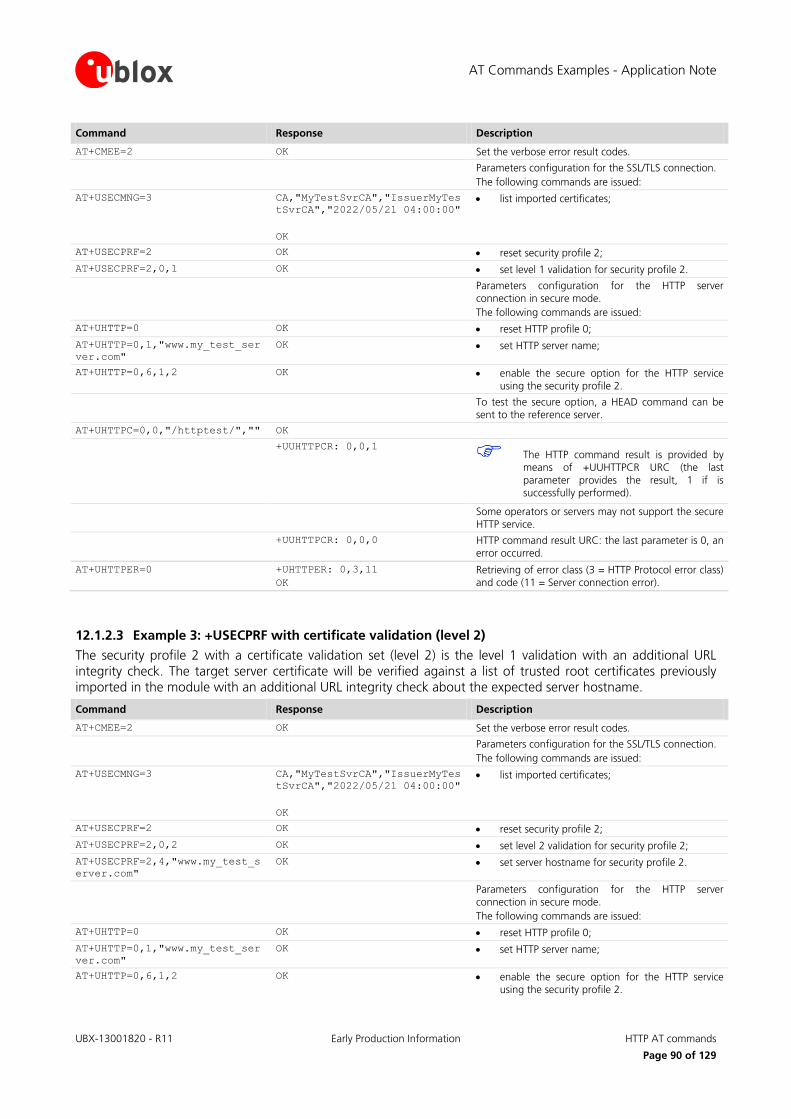
AT Commands Examples - Application Note
UBX-13001820 - R11 Early Production Information HTTP AT commands
Page 90 of 129
Command Response Description
AT+CMEE=2 OK Set the verbose error result codes.
Parameters configuration for the SSL/TLS connection.
The following commands are issued:
AT+USECMNG=3 CA,"MyTestSvrCA","IssuerMyTes
tSvrCA","2022/05/21 04:00:00"
OK
list imported certificates;
AT+USECPRF=2 OK reset security profile 2;
AT+USECPRF=2,0,1 OK set level 1 validation for security profile 2.
Parameters configuration for the HTTP server connection in secure mode.
The following commands are issued:
AT+UHTTP=0 OK reset HTTP profile 0;
AT+UHTTP=0,1,"www.my_test_ser
ver.com"
OK set HTTP server name;
AT+UHTTP=0,6,1,2 OK enable the secure option for the HTTP service using the security profile 2.
To test the secure option, a HEAD command can be sent to the reference server.
AT+UHTTPC=0,0,"/httptest/","" OK
+UUHTTPCR: 0,0,1 The HTTP command result is provided by
means of +UUHTTPCR URC (the last
parameter provides the result, 1 if is successfully performed).
Some operators or servers may not support the secure HTTP service.
+UUHTTPCR: 0,0,0 HTTP command result URC: the last parameter is 0, an error occurred.
AT+UHTTPER=0 +UHTTPER: 0,3,11
OK
Retrieving of error class (3 = HTTP Protocol error class) and code (11 = Server connection error).
12.1.2.3 Example 3: +USECPRF with certificate validation (level 2)
The security profile 2 with a certificate validation set (level 2) is the level 1 validation with an additional URL integrity check. The target server certificate will be verified against a list of trusted root certificates previously imported in the module with an additional URL integrity check about the expected server hostname.
Command Response Description
AT+CMEE=2 OK Set the verbose error result codes.
Parameters configuration for the SSL/TLS connection.
The following commands are issued:
AT+USECMNG=3 CA,"MyTestSvrCA","IssuerMyTes
tSvrCA","2022/05/21 04:00:00"
OK
list imported certificates;
AT+USECPRF=2 OK reset security profile 2;
AT+USECPRF=2,0,2 OK set level 2 validation for security profile 2;
AT+USECPRF=2,4,"www.my_test_s
erver.com"
OK set server hostname for security profile 2.
Parameters configuration for the HTTP server connection in secure mode.
The following commands are issued:
AT+UHTTP=0 OK reset HTTP profile 0;
AT+UHTTP=0,1,"www.my_test_ser
ver.com"
OK set HTTP server name;
AT+UHTTP=0,6,1,2 OK enable the secure option for the HTTP service using the security profile 2.

AT Commands Examples - Application Note
UBX-13001820 - R11 Early Production Information HTTP AT commands
Page 91 of 129
Command Response Description
To test the secure option, a HEAD command can be sent to the reference server.
AT+UHTTPC=0,0,"/httptest/","" OK
+UUHTTPCR: 0,0,1 The HTTP command result is provided by
means of +UUHTTPCR URC (the last parameter provides the result, 1 if is
successfully performed).
Some operators or servers may not support the secure
HTTP service.
+UUHTTPCR: 0,0,0 HTTP command result URC: the last parameter is 0, an error occurred.
AT+UHTTPER=0 +UHTTPER: 0,3,11
OK
Retrieving of error class (3 = HTTP Protocol error class) and code (11 = Server connection error).
12.1.2.4 Example 4: +USECPRF with certificate validation (level 3)
The security profile 2 with a certificate validation set (level 3) is the level 2 validation with an additional check about the certificate validity date. The target server certificate will be verified against a list of trusted root certificates previously imported in the module with additional checks regarding the expected server hostname and the certificate validity date.
Command Response Description
AT+CMEE=2 OK Set the verbose error result codes.
AT+CCLK? +CCLK: "15/11/18,12:30:50+01"
OK
Check the real-time clock of the module and, if necessary, set the current time.
Parameters configuration for the SSL/TLS connection.
The following commands are issued:
AT+USECMNG=3 CA,"MyTestSvrCA","IssuerMyTes
tSvrCA","2022/05/21 04:00:00"
OK
list imported certificates;
AT+USECPRF=2 OK reset security profile 2;
AT+USECPRF=2,0,3 OK set level 3 validation for security profile 2;
AT+USECPRF=2,4,"www.my_test_s
erver.com"
OK set server hostname for security profile 2.
Parameters configuration for the HTTP server
connection in secure mode.
The following commands are issued:
AT+UHTTP=0 OK reset HTTP profile 0;
AT+UHTTP=0,1,"www.my_test_ser
ver.com"
OK set HTTP server name;
AT+UHTTP=0,6,1,2 OK enable the secure option for the HTTP service using the security profile 2.
To test the secure option, a HEAD command can be sent to the reference server.
AT+UHTTPC=0,0,"/httptest/","" OK
+UUHTTPCR: 0,0,1 The HTTP command result is provided by
means of +UUHTTPCR URC (the last
parameter provides the result, 1 if is successfully performed).
Some operators or servers may not support the secure HTTP service.
+UUHTTPCR: 0,0,0 HTTP command result URC: the last parameter is 0, an error occurred.
AT+UHTTPER=0 +UHTTPER: 0,3,11
OK
Retrieving of error class (3 = HTTP Protocol error class) and code (11 = Server connection error).

AT Commands Examples - Application Note
UBX-13001820 - R11 Early Production Information HTTP AT commands
Page 92 of 129
12.1.3 Data security and integrity
An SSL/TLS connection is characterized by its own configuration and features to guarantee specific aspects of the data security and integrity, that is data encryption and Hash Message Authentication (HMAC) generation for checking exchanged messages.
This behavior is closely related to the concept of cipher suites: in fact they represent a named combination of protocol version, authentication and key exchange, encryption and message authentication code algorithms.
In simple terms, ciphers suits are used to specify supported and negotiate SSL/TLS connection properties and algorithms. They are usually identified by a string like the following:
TLS_RSA_WITH_AES_256_CBC_SHA256
the meaning of which is as follows:
TLS protocol is used in communication;
RSA algorithm is utilized for authentication and secure key exchange;
AES_256_CBC is considered for encryption of transmitted data;
SHA256 algorithm is adopted for creating HMAC message integrity code.
See the u-blox AT Commands Manual [1] for the list of all the supported cipher suites, while in the next section is presented an explanation of how to configure the behavior in exam.
12.1.3.1 Example: cipher suite management in SSL/TLS connections
In this context the AT+USECPRF command configures the secure options: in fact it allows the user to choose the cipher suite to be applied in the communication.
The SSL/TLS connection is not established and an error result code is provided if a cipher suite not supported by the target server is selected.
Command Response Description
AT+CMEE=2 OK Set the verbose error result codes.
Parameters configuration for the SSL/TLS connection. The following commands are issued:
AT+USECMNG=3 OK list imported certificates;
AT+USECPRF=2 OK reset security profile 2;
AT+USECPRF=2,2,4 OK set cipher suite number 4, that is TLS_RSA_WITH_AES_256_CBC_SHA256, for security profile 2.
Parameters configuration for the HTTP server connection in secure mode.
The following commands are issued:
AT+UHTTP=0 OK reset HTTP profile 0;
AT+UHTTP=0,1,"www.my_test_ser
ver.com"
OK set HTTP server name;
AT+UHTTP=0,6,1,2 OK enable the secure option for the HTTP service using the security profile 2.
To test the secure option, a HEAD command can be sent to the reference server.
AT+UHTTPC=0,0,"/httptest/","" OK
+UUHTTPCR: 0,0,1 HTTP command result by +UUHTTPCR URC: in this case the HEAD request is successfully performed.
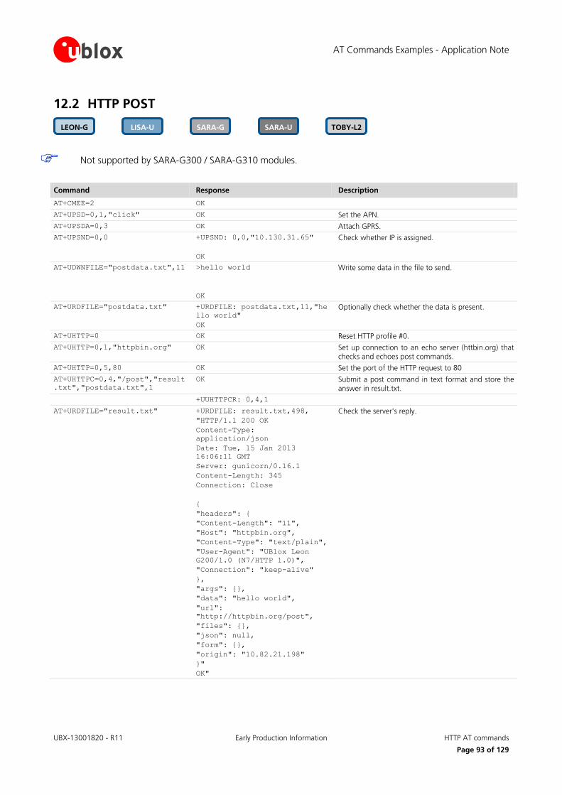
AT Commands Examples - Application Note
UBX-13001820 - R11 Early Production Information HTTP AT commands
Page 93 of 129
12.2 HTTP POST
Not supported by SARA-G300 / SARA-G310 modules.
Command Response Description
AT+CMEE=2 OK
AT+UPSD=0,1,"click" OK Set the APN.
AT+UPSDA=0,3 OK Attach GPRS.
AT+UPSND=0,0 +UPSND: 0,0,"10.130.31.65"
OK
Check whether IP is assigned.
AT+UDWNFILE="postdata.txt",11 >hello world
OK
Write some data in the file to send.
AT+URDFILE="postdata.txt" +URDFILE: postdata.txt,11,"he
llo world"
OK
Optionally check whether the data is present.
AT+UHTTP=0 OK Reset HTTP profile #0.
AT+UHTTP=0,1,"httpbin.org" OK Set up connection to an echo server (httbin.org) that checks and echoes post commands.
AT+UHTTP=0,5,80 OK Set the port of the HTTP request to 80
AT+UHTTPC=0,4,"/post","result
.txt","postdata.txt",1
OK Submit a post command in text format and store the answer in result.txt.
+UUHTTPCR: 0,4,1
AT+URDFILE="result.txt" +URDFILE: result.txt,498,
"HTTP/1.1 200 OK
Content-Type:
application/json
Date: Tue, 15 Jan 2013
16:06:11 GMT
Server: gunicorn/0.16.1
Content-Length: 345
Connection: Close
{
"headers": {
"Content-Length": "11",
"Host": "httpbin.org",
"Content-Type": "text/plain",
"User-Agent": "UBlox Leon
G200/1.0 (N7/HTTP 1.0)",
"Connection": "keep-alive"
},
"args": {},
"data": "hello world",
"url":
"http://httpbin.org/post",
"files": {},
"json": null,
"form": {},
"origin": "10.82.21.198"
}"
OK"
Check the server's reply.
TOBY-L2 SARA-U SARA-G LISA-U LEON-G

AT Commands Examples - Application Note
UBX-13001820 - R11 Early Production Information HTTP AT commands
Page 94 of 129
12.3 HTTP cookies
See the u-blox AT Commands Manual [1] for the AT commands applicability.
Command Response Description
AT+CMEE=2 OK Set the verbose error result codes.
AT+UPSD=0,1,"click" OK Set the APN. The APN name relates to the network operator. The one used here is only an example.
AT+UPSDA=0,3 OK Activate a PDP context.
AT+UPSND=0,0 +UPSND: 0,0,"10.130.31.65"
OK
Check whether IP is assigned. The reported IP address is assigned by the network operator, the one used
here is only an example.
AT+UHTTP=0 OK Set up a connection to an echo server (httbin.org) that checks and echoes post commands.
AT+UHTTPAC=0,0,0,"CKE:SIMPLE" OK Set a simple COOKIE.
AT+UHTTPAC=0,0,0 +UHTTPAC: 0,0,0,"CKE:SIMPLE"
OK
Read the set COOKIE. This step is not mandatory.
AT+UHTTP=0,1,"httpbin.org" OK Set the server host name (httpbin.org is a freely available 3
rd party service. It is not managed or
operated by u-blox).
AT+UHTTP=0,5,80 OK Set the server post.
AT+UHTTPC=0,1,"/get","get.ffs
"
OK Submit a GET command and store the answer in the local file get.ffs on the module file system.
+UUHTTPCR: 0,4,1 The +UUHTTPCR URC indicates the request was successful.
AT+URDFILE="get.ffs" Read the get.ffs file.
+URDFILE:
"get.ffs",418,"HTTP/1.1 200
OK
Server: nginx
Date: Fri, 04 Sep 2015
14:37:07 GMT
Content-Type:
application/json
Content-Length: 203
Connection: close
Access-Control-Allow-Origin:
*
Access-Control-Allow-
Credentials: true
{
"args": {},
"headers": {
"Cookie": "CKE:SIMPLE",
"Host": "httpbin.org",
"User-Agent": "UBLOX-
HttpClient V2.0"
},
"origin": "151.82.163.82",
"url":
"http://httpbin.org/get"
}
"
OK
Content of the get.ffs file where it is possible to see
that the server received the cookie (line marked in red).
TOBY-L2 SARA-U LISA-U
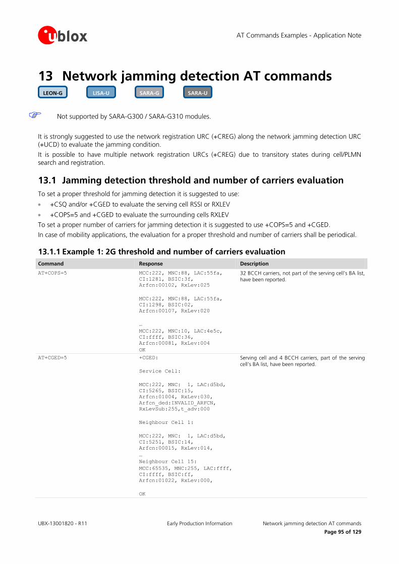
AT Commands Examples - Application Note
UBX-13001820 - R11 Early Production Information Network jamming detection AT commands
Page 95 of 129
13 Network jamming detection AT commands
Not supported by SARA-G300 / SARA-G310 modules.
It is strongly suggested to use the network registration URC (+CREG) along the network jamming detection URC (+UCD) to evaluate the jamming condition.
It is possible to have multiple network registration URCs (+CREG) due to transitory states during cell/PLMN search and registration.
13.1 Jamming detection threshold and number of carriers evaluation
To set a proper threshold for jamming detection it is suggested to use:
+CSQ and/or +CGED to evaluate the serving cell RSSI or RXLEV
+COPS=5 and +CGED to evaluate the surrounding cells RXLEV
To set a proper number of carriers for jamming detection it is suggested to use +COPS=5 and +CGED.
In case of mobility applications, the evaluation for a proper threshold and number of carriers shall be periodical.
13.1.1 Example 1: 2G threshold and number of carriers evaluation
Command Response Description
AT+COPS=5 MCC:222, MNC:88, LAC:55fa,
CI:1281, BSIC:3f,
Arfcn:00102, RxLev:025
MCC:222, MNC:88, LAC:55fa,
CI:1298, BSIC:02,
Arfcn:00107, RxLev:020
…
MCC:222, MNC:10, LAC:4e5c,
CI:ffff, BSIC:36,
Arfcn:00081, RxLev:004
OK
32 BCCH carriers, not part of the serving cell’s BA list, have been reported.
AT+CGED=5 +CGED:
Service Cell:
MCC:222, MNC: 1, LAC:d5bd,
CI:5265, BSIC:15,
Arfcn:01004, RxLev:030,
Arfcn_ded:INVALID_ARFCN,
RxLevSub:255,t_adv:000
Neighbour Cell 1:
MCC:222, MNC: 1, LAC:d5bd,
CI:5251, BSIC:14,
Arfcn:00015, RxLev:014,
…
Neighbour Cell 15:
MCC:65535, MNC:255, LAC:ffff,
CI:ffff, BSIC:ff,
Arfcn:01022, RxLev:000,
OK
Serving cell and 4 BCCH carriers, part of the serving cell’s BA list, have been reported.
SARA-U SARA-G LISA-U LEON-G
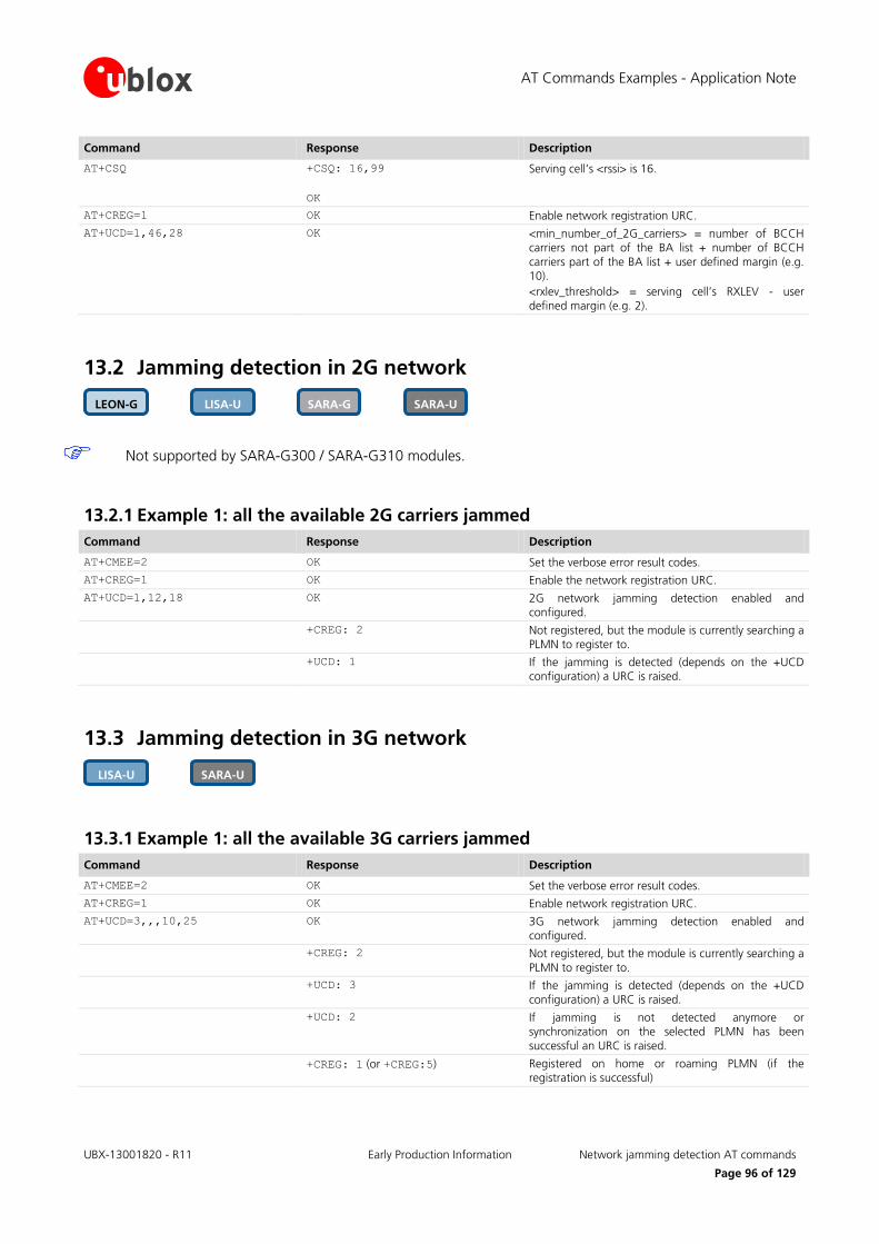
AT Commands Examples - Application Note
UBX-13001820 - R11 Early Production Information Network jamming detection AT commands
Page 96 of 129
Command Response Description
AT+CSQ +CSQ: 16,99
OK
Serving cell’s <rssi> is 16.
AT+CREG=1 OK Enable network registration URC.
AT+UCD=1,46,28 OK <min_number_of_2G_carriers> = number of BCCH carriers not part of the BA list + number of BCCH
carriers part of the BA list + user defined margin (e.g. 10).
<rxlev_threshold> = serving cell’s RXLEV - user
defined margin (e.g. 2).
13.2 Jamming detection in 2G network
Not supported by SARA-G300 / SARA-G310 modules.
13.2.1 Example 1: all the available 2G carriers jammed
Command Response Description
AT+CMEE=2 OK Set the verbose error result codes.
AT+CREG=1 OK Enable the network registration URC.
AT+UCD=1,12,18 OK 2G network jamming detection enabled and configured.
+CREG: 2 Not registered, but the module is currently searching a PLMN to register to.
+UCD: 1 If the jamming is detected (depends on the +UCD configuration) a URC is raised.
13.3 Jamming detection in 3G network
13.3.1 Example 1: all the available 3G carriers jammed
Command Response Description
AT+CMEE=2 OK Set the verbose error result codes.
AT+CREG=1 OK Enable network registration URC.
AT+UCD=3,,,10,25 OK 3G network jamming detection enabled and configured.
+CREG: 2 Not registered, but the module is currently searching a
PLMN to register to.
+UCD: 3 If the jamming is detected (depends on the +UCD configuration) a URC is raised.
+UCD: 2 If jamming is not detected anymore or synchronization on the selected PLMN has been successful an URC is raised.
+CREG: 1 (or +CREG:5) Registered on home or roaming PLMN (if the registration is successful)
SARA-U LISA-U
SARA-U SARA-G LISA-U LEON-G

AT Commands Examples - Application Note
UBX-13001820 - R11 Early Production Information Network jamming detection AT commands
Page 97 of 129
13.4 Jamming detection in 2G/3G network
13.4.1 Example 1: all the available 2G and 3G carriers jammed
Command Response Description
AT+CMEE=2 OK Set the verbose error result codes.
AT+CREG=1 OK Enable network registration URC.
AT+UCD=4,12,18,10,25 OK 2G and 3G network jamming detection enabled and configured.
+CREG: 2 Not registered, but the module is currently searching a
PLMN to register to.
+UCD: 1 If jamming is detected (depends on the +UCD configuration) a URC is raised.
+UCD: 3 If jamming is detected (depends on the +UCD configuration) URC is raised.
The 2G jamming indication URC and 3G jamming indication URC order can be inverted.
13.5 Advanced jamming detection in 2G network
Not supported by LEON-G100-07S / LEON-G200-07S and previous versions.
Not supported by SARA-G300 / SARA-G310 modules.
13.5.1 Example 1: all the available 2G carriers jammed
Command Response Description
AT+CMEE=2 OK Set the verbose error result codes.
AT+CREG=1 OK Enable the network registration URC.
AT+UCD=5,30,35 OK 2G network advanced jamming detection enabled and configured. The selected PLMN is retrieved from
the IMSI.
+CREG: 2 Not registered, but the module is currently searching a PLMN to register to.
+UCD: 1 If the jamming is detected (depends on the +UCD configuration) and synchronization on the selected PLMN is not possible, an URC is raised.
+UCD: 0 If the jamming is not detected anymore (e.g. jamming source switched off) or the synchronization on the selected PLMN has been successful (e.g. a selected
PLMN’s BCCH carrier stronger than the jamming source has been found), an URC is raised.
+CREG: 1 (or +CREG:5) Registered on home or roaming PLMN (if the registration is successful).
SARA-U SARA-G LEON-G
SARA-U LISA-U
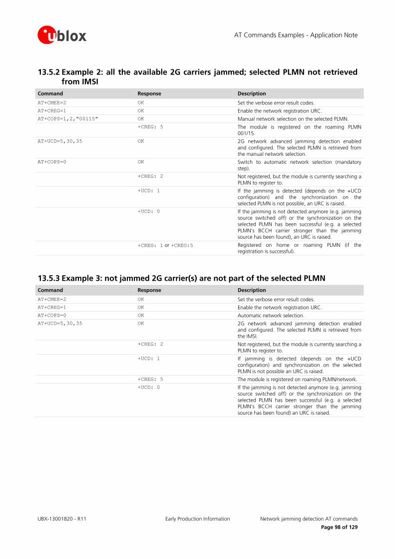
AT Commands Examples - Application Note
UBX-13001820 - R11 Early Production Information Network jamming detection AT commands
Page 98 of 129
13.5.2 Example 2: all the available 2G carriers jammed; selected PLMN not retrieved from IMSI
Command Response Description
AT+CMEE=2 OK Set the verbose error result codes.
AT+CREG=1 OK Enable the network registration URC.
AT+COPS=1,2,"00115" OK Manual network selection on the selected PLMN.
+CREG: 5 The module is registered on the roaming PLMN 001/15.
AT+UCD=5,30,35 OK 2G network advanced jamming detection enabled
and configured. The selected PLMN is retrieved from the manual network selection.
AT+COPS=0 OK Switch to automatic network selection (mandatory
step).
+CREG: 2 Not registered, but the module is currently searching a PLMN to register to.
+UCD: 1 If the jamming is detected (depends on the +UCD configuration) and the synchronization on the selected PLMN is not possible, an URC is raised.
+UCD: 0 If the jamming is not detected anymore (e.g. jamming source switched off) or the synchronization on the selected PLMN has been successful (e.g. a selected
PLMN’s BCCH carrier stronger than the jamming source has been found), an URC is raised.
+CREG: 1 or +CREG:5 Registered on home or roaming PLMN (if the registration is successful).
13.5.3 Example 3: not jammed 2G carrier(s) are not part of the selected PLMN
Command Response Description
AT+CMEE=2 OK Set the verbose error result codes.
AT+CREG=1 OK Enable the network registration URC.
AT+COPS=0 OK Automatic network selection.
AT+UCD=5,30,35 OK 2G network advanced jamming detection enabled and configured. The selected PLMN is retrieved from
the IMSI.
+CREG: 2 Not registered, but the module is currently searching a PLMN to register to.
+UCD: 1 If jamming is detected (depends on the +UCD configuration) and synchronization on the selected PLMN is not possible an URC is raised.
+CREG: 5 The module is registered on roaming PLMN/network.
+UCD: 0 If the jamming is not detected anymore (e.g. jamming source switched off) or the synchronization on the
selected PLMN has been successful (e.g. a selected PLMN’s BCCH carrier stronger than the jamming
source has been found) an URC is raised.

AT Commands Examples - Application Note
UBX-13001820 - R11 Early Production Information Cell lock AT commands
Page 99 of 129
14 Cell lock AT commands
Not supported by LEON-G100-07x / LEON-G200-07S and previous versions.
Not supported by LISA-U1 series or by LISA-U2x0-x1S and previous versions.
Not supported by TOBY-L2 "00S", "01S" and "60S" product versions.
14.1 Cell lock in single mode
14.1.1 Cell lock in 2G network: normal mode
Not supported by SARA-G300 / SARA-G310 modules.
Command Response Description
AT+COPS=2 OK Deregister the module prior to the lock.
AT+UCELLLOCK=3,100,0 OK A normal cell lock is set on ARFCN 100 enabling the URC.
AT+COPS=0 OK Set automatic network selection.
+UCELLLOCK: 1 If the URC mode is enabled then the cell lock state
will be reported. In normal mode the module performs handovers during the connected mode. If a
handover is performed or if the locking cell is lost the state will accordingly change.
AT+COPS=2 OK Deregister the module prior disabling the lock.
AT+UCELLLOCK=0 OK Disable cell lock.
14.1.2 Cell lock in 2G network: extended mode
Not supported by SARA-G300 / SARA-G310 modules.
Command Response Description
AT+COPS=2 OK Deregister the module prior to the lock.
AT+UCELLLOCK=5,600,1 OK A normal cell lock is issued on ARFCN 600 of band 1900 with URC enabled.
AT+COPS=0 OK Set automatic network selection.
+UCELLLOCK: 1 If the URC mode is enabled then the cell lock state will be reported. In extended mode the module does
not perform any handover during connected mode. A change of serving cell is still possible. If the service cell is changed or if the locking cell is lost the state will
change accordingly.
AT+COPS=2 OK Deregister the module prior disabling the lock.
AT+UCELLLOCK=0 OK Disable cell lock.
TOBY-L2 SARA-U LISA-U SARA-G LEON-G
TOBY-L2 SARA-U LISA-U SARA-G LEON-G

AT Commands Examples - Application Note
UBX-13001820 - R11 Early Production Information Cell lock AT commands
Page 100 of 129
14.1.3 Cell lock in 2G network: normal mode
Command Response Description
AT+CMEE=2 OK Set the verbose error result codes.
AT+COPS=2 OK Deregister the module prior the lock.
AT+URAT=0 OK Set the GSM RAT.
AT+UCELLLOCK=3,100,0 OK A normal cell lock is set on ARFCN 100 enabling the URC.
AT+COPS=0 OK Set automatic network selection.
+UCELLLOCK: 1,1 If the URC mode is enabled then the cell lock state will be reported. In normal mode the module performs handovers if in a connection. The state will
accordingly change due to a handover or to the locking cell loss.
AT+UCELLLOCK=0 OK The cell lock is disabled.
14.1.4 Cell lock in 2G network: extended mode
Command Response Description
AT+CMEE=2 OK Set the verbose error result codes.
AT+COPS=2 OK Deregister the module prior the lock.
AT+URAT=0 OK Set the GSM RAT.
AT+UCELLLOCK=5,600,1 OK An extended cell lock is issued on ARFCN 600 of band 1900 with URC enabled.
AT+COPS=0 OK Set automatic network selection.
+UCELLLOCK: 1,1 If the URC mode is enabled then the cell lock state will be reported. In extended mode the module does not perform any handover if in a connection. A
change of serving cell is still possible. The state will change accordingly due to a serving cell change or to
the locking cell loss.
AT+UCELLLOCK=0 OK The cell lock is disabled.
14.1.5 Cell lock in 3G network: normal mode
Command Response Description
AT+CMEE=2 OK Set the verbose error result codes.
AT+COPS=2 OK Deregister the module prior the lock.
AT+URAT=2 OK Set the UMTS RAT.
AT+UCELLLOCK=3,,,10838,6 OK A normal cell lock is set on UARFCN 10838, PSC 6 enabling the URC.
AT+COPS=0 OK Set automatic network selection.
TOBY-L2 SARA-U LISA-U
TOBY-L2 SARA-U LISA-U
TOBY-L2 SARA-U LISA-U

AT Commands Examples - Application Note
UBX-13001820 - R11 Early Production Information Cell lock AT commands
Page 101 of 129
Command Response Description
+UCELLLOCK: 1,2 If the URC mode is enabled then the cell lock state will be reported. In normal mode the module
performs soft/hard handovers if in a connection or any physical/transport/radio bearer reconfiguration that
implies a change of UARFCN and/or PSC. The state will accordingly change due to a handover or to the locking cell loss.
AT+UCELLLOCK=0 OK The cell lock is disabled.
14.1.6 Cell lock in 3G network: extended mode
Command Response Description
AT+CMEE=2 OK Set the verbose error result codes.
AT+COPS=2 OK Deregister the module prior the lock.
AT+URAT=2 OK Set the UMTS RAT.
AT+UCELLLOCK=5,,,10838,6 OK An extended cell lock is set on UARFCN 10838, PSC 6 enabling the URC.
AT+COPS=0 OK Set automatic network selection.
+UCELLLOCK: 1,2 If the URC mode is enabled then the cell lock state will be reported. In extended mode the module does not perform any soft/hard handovers if in a
connection but it will still obey to physical/transport/radio bearer reconfiguration that
implies a change of UARFCN and/or PSC. The state will accordingly change due to a handover or to the
locking cell loss.
AT+UCELLLOCK=0 OK The cell lock is disabled.
14.1.7 Cell lock in 3G network: extended + redirection mode
Command Response Description
AT+CMEE=2 OK Set the verbose error result codes.
AT+COPS=2 OK Deregister the module prior the lock.
AT+UCELLLOCK=7,,,10838,6 OK An extended + redirection cell lock is set on UARFCN 10838, PSC 6 enabling the URC.
AT+URAT=2 OK Set the UMTS RAT.
AT+COPS=0 OK Set automatic network selection.
+UCELLLOCK: 1,2 If the URC mode is enabled then the cell lock state will be reported. In extended mode the module does
not perform any soft/hard handovers if in a connection and does not obey to
physical/transport/radio bearer reconfiguration that implies a change of UARFCN and/or PSC. The state
will accordingly change due to a handover or to the locking cell loss.
AT+UCELLLOCK=0 OK The cell lock is disabled.
TOBY-L2 SARA-U LISA-U
TOBY-L2 SARA-U LISA-U

AT Commands Examples - Application Note
UBX-13001820 - R11 Early Production Information Cell lock AT commands
Page 102 of 129
14.1.8 Cell lock in 4G network: normal mode
Command Response Description
AT+CMEE=2 OK Set the verbose error result codes.
AT+COPS=2 OK Deregister the module prior the lock.
AT+URAT=3 OK Set the LTE RAT.
AT+UCELLLOCK=3,,,,,900,0 OK A normal cell lock is set on EARFCN 900, P-CID 0 enabling the URC.
AT+COPS=0 OK Set automatic network selection.
+UCELLLOCK: 1,3 The URC reports the cell lock state. In normal mode the module performs soft/hard handovers if in a connection or any physical/transport/radio bearer
reconfiguration that implies a change of UARFCN and/or PSC. The state will accordingly change due to a
handover or to the locking cell loss.
AT+UCELLLOCK=0 OK The cell lock is disabled.
14.1.9 Cell lock in 4G network: extended mode
Command Response Description
AT+CMEE=2 OK Set the verbose error result codes.
AT+COPS=2 OK Deregister the module prior the lock.
AT+URAT=3 OK Set the LTE RAT.
AT+UCELLLOCK=5,,,,,6300,337 OK An extended cell lock is set on EARFCN 6300, P-CID 337 enabling the URC.
AT+COPS=0 OK Set automatic network selection.
+UCELLLOCK: 1,3 The URC reports the cell lock state. In extended mode the module does not perform any soft/hard handovers
if in a connection but it will still obey to physical/transport/radio bearer reconfiguration that
implies a change of UARFCN and/or PSC. The state will accordingly change due to a handover or to the
locking cell loss.
AT+UCELLLOCK=0 OK The cell lock is disabled.
14.1.10 Cell lock in 4G network: extended + redirection mode
Command Response Description
AT+CMEE=2 OK Set the verbose error result codes.
AT+COPS=2 OK Deregister the module prior the lock.
AT+UCELLLOCK=7,,,,,6300,337 OK An extended + redirection cell lock is set on EARFCN 6300, P-CID 337 enabling the URC.
AT+URAT=3 OK Set the LTE RAT.
AT+COPS=0 OK Set automatic network selection.
TOBY-L2
TOBY-L2
TOBY-L2
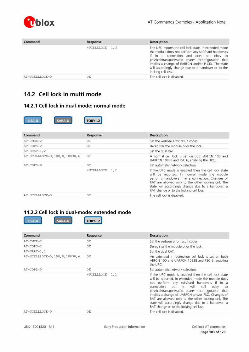
AT Commands Examples - Application Note
UBX-13001820 - R11 Early Production Information Cell lock AT commands
Page 103 of 129
Command Response Description
+UCELLLOCK: 1,3 The URC reports the cell lock state. In extended mode the module does not perform any soft/hard handovers
if in a connection and does not obey to physical/transport/radio bearer reconfiguration that
implies a change of EARFCN and/or P-CID. The state will accordingly change due to a handover or to the locking cell loss.
AT+UCELLLOCK=0 OK The cell lock is disabled.
14.2 Cell lock in multi mode
14.2.1 Cell lock in dual-mode: normal mode
Command Response Description
AT+CMEE=2 OK Set the verbose error result codes.
AT+COPS=2 OK Deregister the module prior the lock.
AT+URAT=1,2 Set the dual RAT.
AT+UCELLLOCK=3,100,0,10838,6 OK A normal cell lock is set on both ARFCN 100 and UARFCN 10838 and PSC 6, enabling the URC.
AT+COPS=0 OK Set automatic network selection.
+UCELLLOCK: 1,2 If the URC mode is enabled then the cell lock state will be reported. In normal mode the module
performs handovers if in a connection. Changes of RAT are allowed only to the other locking cell. The
state will accordingly change due to a handover, a RAT change or to the locking cell loss.
AT+UCELLLOCK=0 OK The cell lock is disabled.
14.2.2 Cell lock in dual-mode: extended mode
Command Response Description
AT+CMEE=2 OK Set the verbose error result codes.
AT+COPS=2 OK Deregister the module prior the lock.
AT+URAT=1,2 Set the dual RAT.
AT+UCELLLOCK=5,100,0,10838,6 OK An extended + redirection cell lock is set on both ARFCN 100 and UARFCN 10838 and PSC 6, enabling
the URC.
AT+COPS=0 OK Set automatic network selection.
+UCELLLOCK: 1,1 If the URC mode is enabled then the cell lock state will be reported. In extended mode the module does
not perform any soft/hard handovers if in a connection but it will still obey to
physical/transport/radio bearer reconfiguration that implies a change of UARFCN and/or PSC. Changes of
RAT are allowed only to the other locking cell. The state will accordingly change due to a handover, a
RAT change or to the locking cell loss.
AT+UCELLLOCK=0 OK The cell lock is disabled.
TOBY-L2 SARA-U LISA-U
TOBY-L2 SARA-U LISA-U

AT Commands Examples - Application Note
UBX-13001820 - R11 Early Production Information Cell lock AT commands
Page 104 of 129
14.2.3 Cell lock in dual-mode: extended + redirection mode
Command Response Description
AT+CMEE=2 OK Set the verbose error result codes.
AT+COPS=2 OK Deregister the module prior the lock.
AT+URAT=1,2 Set the dual RAT.
AT+UCELLLOCK=7,100,0,10838,6 OK An extended cell lock is set on both ARFCN 100 and UARFCN 10838 and PSC 6, enabling the URC.
AT+COPS=0 OK Set automatic network selection.
+UCELLLOCK: 1,1 If the URC mode is enabled then the cell lock state will be reported. In extended mode the module does not perform any soft/hard handovers if in a
connection and does not obey to physical/transport/radio bearer reconfiguration that
implies a change of UARFCN and/or PSC. In 2G this is equivalent to the extended mode. Changes of RAT are
allowed only to the other locking cell. The state will accordingly change due to a handover, a RAT change
or to the locking cell loss.
AT+UCELLLOCK=0 OK The cell lock is disabled.
14.2.4 Cell lock in tri-mode: normal mode
Command Response Description
AT+CMEE=2 OK Set the verbose error result codes.
AT+COPS=2 OK Deregister the module prior the lock.
AT+URAT=4,3 Set the tri RAT.
AT+UCELLLOCK=3,100,0,10838,6,
6300,337
OK A normal cell lock is set on 2G cell ARFCN 100, 3G cell UARFCN 10838, PSC 6 and 4G cell EARFCN 6300, P-CID 337, enabling the URC.
AT+COPS=0 OK Set automatic network selection.
+UCELLLOCK: 1,3 The module searches for any of the three locking cells and camps on the first cell found. The URC reports
the cell lock state. In normal mode the module performs handovers if in a connection. Changes of
RAT are allowed only to the other locking cell. The state will accordingly change due to a handover, a
RAT change or to the locking cell loss.
AT+UCELLLOCK=0 OK The cell lock is disabled.
14.2.5 Cell lock in tri-mode: extended mode
Command Response Description
AT+CMEE=2 OK Set the verbose error result codes.
AT+COPS=2 OK Deregister the module prior the lock.
AT+URAT=4,3 Set the tri RAT.
TOBY-L2
TOBY-L2
TOBY-L2 SARA-U LISA-U
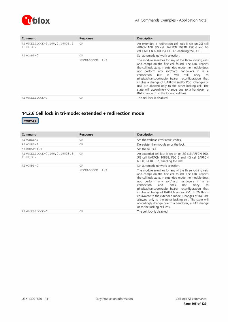
AT Commands Examples - Application Note
UBX-13001820 - R11 Early Production Information Cell lock AT commands
Page 105 of 129
Command Response Description
AT+UCELLLOCK=5,100,0,10838,6,
6300,337
OK An extended + redirection cell lock is set on 2G cell ARFCN 100, 3G cell UARFCN 10838, PSC 6 and 4G
cell EARFCN 6300, P-CID 337, enabling the URC.
AT+COPS=0 OK Set automatic network selection.
+UCELLLOCK: 1,3 The module searches for any of the three locking cells and camps on the first cell found. The URC reports
the cell lock state. In extended mode the module does not perform any soft/hard handovers if in a
connection but it will still obey to physical/transport/radio bearer reconfiguration that
implies a change of UARFCN and/or PSC. Changes of RAT are allowed only to the other locking cell. The
state will accordingly change due to a handover, a RAT change or to the locking cell loss.
AT+UCELLLOCK=0 OK The cell lock is disabled.
14.2.6 Cell lock in tri-mode: extended + redirection mode
Command Response Description
AT+CMEE=2 OK Set the verbose error result codes.
AT+COPS=2 OK Deregister the module prior the lock.
AT+URAT=4,3 Set the tri RAT.
AT+UCELLLOCK=7,100,0,10838,6,
6300,337
OK An extended cell lock is set on on 2G cell ARFCN 100, 3G cell UARFCN 10838, PSC 6 and 4G cell EARFCN 6300, P-CID 337, enabling the URC.
AT+COPS=0 OK Set automatic network selection.
+UCELLLOCK: 1,3 The module searches for any of the three locking cells and camps on the first cell found. The URC reports
the cell lock state. In extended mode the module does not perform any soft/hard handovers if in a connection and does not obey to
physical/transport/radio bearer reconfiguration that implies a change of UARFCN and/or PSC. In 2G this is
equivalent to the extended mode. Changes of RAT are allowed only to the other locking cell. The state will
accordingly change due to a handover, a RAT change or to the locking cell loss.
AT+UCELLLOCK=0 OK The cell lock is disabled.
TOBY-L2

AT Commands Examples - Application Note
UBX-13001820 - R11 Early Production Information ADC AT commands
Page 106 of 129
15 ADC AT commands
Not supported by LEON-G200 versions.
Command Response Description
AT+CMEE=2 OK Set the verbose error result codes.
AT+UADC=? +UADC: (0)
OK List of the supported ADCs.
AT+UADC=0 +UADC: 0,473
OK
Check the current value (in milliVolts) of the specified ADC.
16 GPIO AT commands
Not supported by SARA-G300 / SARA-G310 modules.
For more details about GPIO pin mapping, see the corresponding module system integration manual [3], [6], [7].
Command Response Description
AT+CMEE=2 OK Set the verbose error result codes.
AT+UGPIOR=? +UGPIOR: (20, 21)
OK
List of GPIO pin numbers.
AT+UGPIOC=20,0,0
AT+UGPIOC=21,1
OK
OK
Set up the GPIO input / output mode:
GPIO1 in output mode with default value 0
GPIO2 in input mode (no default value can be set)
AT+UGPIOR=20
AT+UGPIOR=21
+UGPIOR: 20,0
OK
+UGPIOR: 21,1
OK
Read the GPIO status.
AT+UGPIOW=20,1 OK Write (set) the GPIO status.
Only GPIO configured in output mode can
be written.
AT+UGPIOC=21,2 OK Configure GPIO2 to be used as network indication.
AT+UGPIOC=? +UGPIOC: (20,21),(0-3),(0-1)
20, 0, 1
21, 2
OK
Provides GPIO status (GPIO1 is an output with value 0 and GPIO2 is set as network configuration).
On LISA-U / SARA-U series the configuration of each GPIO pin is provided
through the read command.
AT+UGPIOW=21,1 +CME ERROR: Write GPIO error Write into a GPIO in input mode. An error is returned.
SARA-U SARA-G LISA-U LEON-G
LEON-G
AT Commands Examples - Application Note
UBX-13001820 - R11 Early Production Information Multiplexer AT commands
Page 107 of 129
17 Multiplexer AT commands
Not supported by TOBY-L2x0-00S modules.
u-blox cellular modules provide the following virtual channels:
Channel 0: control channel
Channel 1 – 5: AT commands / data connection
Channel 6: GNSS tunneling
SARA-U and LISA-U2 series (except LISA-U200-00S version) provide an additional virtual channel:
Channel 7: SAP (SIM Access Profile)
AT+CMUX command must be sent by the mux driver on the host. When the control channel is closed, the mux is disabled. To close the mux channel it is necessary to stop the mux driver; after this the channel #0 will not be seen as a virtual port.
Command Response Description
AT+CMEE=2 OK Set verbose error result codes.
AT+CMUX=0,0,0,1400,253,3,254,
0,0
OK Enable the multiplexer on the module. Once it is started the connection is handled using the
multiplexing protocol as defined in 3GPP 27.010 [2].
TOBY-L2 SARA-U SARA-G LISA-U LEON-G

AT Commands Examples - Application Note
UBX-13001820 - R11 Early Production Information File system AT commands
Page 108 of 129
18 File system AT commands
Not supported by SARA-G300 / SARA-G310 modules.
The commands in this section refer to the module’s local file system. The size of the file system is limited by the available memory. See u-blox AT Commands Manual [1].
Command Response Description
AT+CMEE=2 OK Set the verbose error result codes.
AT+ULSTFILE= +ULSTFILE:"a_file","another_f
ile","mydata"
OK
List all the files in the file system.
AT+ULSTFILE=1 +ULSTFILE: 1012131
OK
Get free space in the file system (in bytes).
AT+ULSTFILE=2,"a_file" +ULSTFILE: 24365
OK
Get file size of "a_file" file (in bytes).
AT+ULSTFILE=2,"some_name" +ULSTFILE: 0
OK
If the specified file does not exist a 0 bytes dimension is returned.
AT+UDWNFILE="new_file",12 > Request the creation of a new file on file system specifying file name and file size (in bytes).
Wait for ">" symbol indicating the data prompt is now
open (AT commands are not allowed in data prompt).
Hello World! OK Send to the serial port the bytes to be written in the specified file.
It is not possible to write fewer bytes than previously specified with AT+UDWNFILE command.
If more bytes are written respect to the threshold, the remaining bytes will be truncated.
The interface is blocked until all the bytes are written.
When the requested number of bytes is written, the module exits from data prompt, OK is returned if no
error occurred during file creation.
AT+ULSTFILE= +ULSTFILE:"a_file","another_f
ile","mydata","new_file"
OK
List again all the files in the file system.
AT+ULSTFILE=2,"new_file" +ULSTFILE: 12
OK
Get file size of "new_file" file (in bytes). The size is
exactly the size requested when the file was created
with +UDWNFILE.
AT+URDFILE="new_file" +URDFILE: new_file,12,"Hello
World!"
OK
Read the just created file ("new_file").
AT+UDELFILE="new_file" OK Delete the file called "new_file".
AT+ULSTFILE= +ULSTFILE:"a_file","another_f
ile","mydata"
OK
List all the files in the file system.
SARA-U SARA-G LISA-U LEON-G
AT Commands Examples - Application Note
UBX-13001820 - R11 Early Production Information SIM toolkit
Page 109 of 129
19 SIM toolkit
SIM Application Toolkit (SAT) is a set of commands and procedures which may be used during a GSM session. The SAT provides mechanisms which allow applications, existing in the SIM, to interact and operate with any MT, which supports the specific mechanisms required by the application.
The specifications related to SIM toolkit are u-blox AT Commands Manual [1], 3GPP TS 27.010 [2], 3GPP TS 51.011 [4] and 3GPP TS 51.014 [5].
Similarly, USAT (USIM Application Toolkit) provides mechanisms which allow applications, existing in the UICC, to interact and operate with any ME which supports the specific mechanism(s) required by the application (3GPP TS 31.111 [8]).
The SAT (or USAT) can be activated by sending +CFUN=6; this enables the SIM-toolkit interface and fetching of proactive commands by SIM-APPL from the SIM-card. After the activation of the SIM toolkit interface, the +STKPRO URC displays the setup menu when available from the SIM (immediately or after PIN insertion).
The commands in this section work properly only if the DTE has activated the SIM toolkit interface. Otherwise the SIM-toolkit processing will be blocked.
In the following sections, SIM is equivalent to USIM and SAT is equivalent to USAT.
19.1 Profile download
The profile downloading provides a mechanism for the MT to tell the SIM what it is capable of, and the SIM can then limit its instruction range accordingly. If the MT does not send the terminal profile, the SIM shall assume that the MT does not support SIM Application Toolkit.
The +STKPROF AT command can query the Terminal Profile and the information text response is the list of SAT facilities supported by the MT, as specified in 3GPP TS 51.014 [5] or in 3GPP TS 31.111 [8].
Command Response Description
AT+CFUN=6 OK SAT activation (if not already enabled).
AT+STKPROF? +STKPROF: 17,"FFFFFFFF7F0300D
F7F00000000010A0003"
OK
The reading result of the terminal profile data.
The terminal profile is sent at power up from MT to SIM, no matter if SAT is enabled or not.
19.2 Proactive SIM
A proactive SIM is a SIM that is capable of issuing commands to the MT. The MT is always the "master" and initiates commands to the SIM, and therefore there is no mechanism for the SIM to initiate a communication with the MT. This limits the possibility of introducing new SIM features requiring the support of the MT, as the MT needs to know in advance what actions it should take. The SIM shall execute all SAT proactive commands or procedures in such a way as not to jeopardize, or cause suspension, of service provisioning to the user.
Proactive SIM gives a mechanism whereby the SIM can initiate actions to be taken by the MT. These actions include:
Displaying text from the SIM to the MT
Sending a short message
Setting up a voice call to a number held by the SIM
SARA-U SARA-G LISA-U LEON-G

AT Commands Examples - Application Note
UBX-13001820 - R11 Early Production Information SIM toolkit
Page 110 of 129
Setting up a data call to a number and bearer capabilities held by the SIM
Sending an SS control or USSD string
Playing tone in earpiece
Initiating a dialogue with the user
SIM initialization request and notification of changes to EF(s)
Providing local information from the MT to the SIM
Communicating with the additional card(s) (if class "a" is supported)
Providing information about the additional card reader(s) (if class "a" is supported)
Managing timers running physically in the MT
Running an AT command received from the SIM, and returning the result to the SIM (if class "b" is supported)
Sending DTMF
Requesting the MT to launch the browser corresponding to a URL (if class "c" is supported)
Establishing and managing a bearer independent protocol (if class "e" is supported)
The information text response to the test command of +STKPRO lists the supported proactive commands.
Command Response Description
AT+CFUN=6 OK SAT activation (if not already enabled).
AT+STKPRO=? +STKPRO: (01,05,16,17,18,19,2
0,21,32,33,34,35,36,37,38,40,
53)
OK
List of the supported proactive commands.
Referring to 3GPP TS 51.014 [5] (or ETSI 102.223 [9]), this means that the module supports the following proactive commands:
01 (0x01) – REFRESH
05 (0x05) – SETUP EVENT LIST
16 (0x10) – SETUP CALL
17 (0x11) – SEND SS
18(0x12) – SEND USSD
19(0x13) – SEND SMS
20(0x14) – SEND DTMF
21(0x15) – LAUNCH BROWSER
32 (0x20) – PLAY TONE
33 (0x21) – DISPLAY TEXT
34 (0x22) – GET INKEY
35 (0x23) – GET INPUT
36 (0x24) – SELECT ITEM
37 (0x25) – SETUP MENU
38 (0x26) – PROVIDE LOCAL INFO
40 (0x28) – SETUP IDLE MODE TEXT
53 (0x35) – LANGUAGE NOTIFICATION
AT Commands Examples - Application Note
UBX-13001820 - R11 Early Production Information SIM toolkit
Page 111 of 129
19.3 Example
19.3.1 Enable the SAT and terminal response
Command Response Description
AT+CFUN=6 OK SAT activation (if not already enabled).
+STKPRO: 37,"STK-
JavaCard",1,1,"AA",0
The URC displays the SAT main menu.
AT+STKTR=37,0 OK Response to the previous SIM Toolkit proactive command which has been displayed by the +STKPRO
URC.
+STKCNF: 37,0,255,144 URC displaying the SAT proactive session status:
37: set up menu
0: command performed successfully
255: no additional info
144: normal ending of the command
19.3.2 Changing the terminal profile
Command Response Description
AT+CFUN=6 OK SAT activation (if not already enabled).
+STKPRO: 37,"STK-
JavaCard",1,1,"AA",0
The URC provides the SAT main menu.
AT+STKTR=37,0 OK Response to the previous SIM Toolkit proactive command which has been displayed by the +STKPRO URC.
+STKCNF: 37,0,255,144 URC displaying the SAT proactive session status:
37: set up menu
0: command performed successfully
255: no additional info
144: normal ending of the command
AT+STKPROF? +STKPROF: 17,"FFFFFFFF7F0300D
F7F00000000010A0003"
OK
The reading result of the terminal profile data.
AT+STKPROF=2,"FF03" OK Modify the terminal profile value.
AT+CPWROFF OK Switch off the module to save the current
configuration.
(powering on module again)
AT+STKPROF? +CME ERROR: operation not
allowed
The SAT must be activated at next power up.
AT+CFUN=6 OK SAT activation (if not already enabled).
AT+STKPROF? +STKPROF: 2,"FF03"
OK
The reading result of the terminal profile data.
AT+STKPROF=0 OK Forces a reset to the default terminal profile stored in the MT.
AT+STKPROF? +STKPROF: 17,"FFFFFFFF7F0300D
F7F00000000010A0003"
OK
The reading result of the terminal profile data.
AT+CPWROFF OK Switch off the module to save the current configuration.

AT Commands Examples - Application Note
UBX-13001820 - R11 Early Production Information SIM toolkit
Page 112 of 129
19.3.3 Entering SAT menu and selecting an item
Command Response Description
AT+CFUN=6 OK SAT activation (if not already enabled).
+STKPRO: 37,"STK-
JavaCard",1,1,"AA",0
The URC displays the SAT main menu.
AT+STKTR=37,0 OK Response to the previous SIM Toolkit proactive command which has been displayed by the URC
+STKPRO.
+STKCNF: 37,0,255,144 URC displaying the SAT proactive session status:
37: set up menu
0: command performed successfully
255: no additional info
144: normal ending of the command
AT+STKENV=211,1 +STKCNF: 129,0,255,145
OK
Send command "Menu Selection" to the SIM.
The +STKCNF command displays the proactive session
status:
129: end of proactive session
0: command performed successfully
255: no additional info
145: normal ending of the command
+STKPRO: 36,"Commands",1,6,"S
IM - ME",0,0
+STKPRO: 36,"Commands",2,6,"S
IM - Display",0,0
+STKPRO: 36,"Commands",3,6,"S
IM - Earpiece",0,0
+STKPRO: 36,"Commands",4,6,"S
IM - Network",0,0
+STKPRO: 36,"Commands",5,6,"S
IM - Card reader",0,0
+STKPRO: 36,"Commands",6,6,"S
pecial",0,0
SAT submenu consisting in 6 items of type "Select
item".
AT+STKTR=36,0,0,0,0,"02" OK Terminal response: select item "2".
+STKCNF: 36,0,255,144 Proactive session status.
+STKPRO: 36,"Display
Text",1,3,"ASCII 7 bit",0,0
+STKPRO: 36,"Display
Text",2,3,"UCS2",0,0
+STKPRO: 36,"Display
Text",3,3,"Icon",0,0
SAT submenu consisting in 3 items of type "Select item".
AT Commands Examples - Application Note
UBX-13001820 - R11 Early Production Information SIM toolkit
Page 113 of 129
19.3.4 Call setup
Command Response Description
AT+CFUN=6 OK Activate the SAT (if not already enabled).
+STKPRO: 37,"STK-
JavaCard",1,1,"AA",0
SAT URC which displays to user the SAT main menu.
AT+STKTR=37,0 OK Response to the previous SIM Toolkit proactive command which has been displayed by the URC
+STKPRO.
+STKCNF: 37,0,255,144 URC displaying the SAT proactive session status:
37: set up menu
0: command performed successfully
255: no additional info
144: normal ending of the command
AT+STKENV=211,1 +STKCNF: 129,0,255,145
OK
Send command "Menu Selection" to the SIM.
The +STKCNF URC displays the proactive session status:
129: end of proactive session
0: command performed successfully
255: no additional info
145: normal ending of the command
+STKPRO: 36,"Commands",1,6,"S
IM - ME",0,0
+STKPRO: 36,"Commands",2,6,"S
IM - Display",0,0
+STKPRO: 36,"Commands",3,6,"S
IM - Earpiece",0,0
+STKPRO: 36,"Commands",4,6,"S
IM - Network",0,0
+STKPRO: 36,"Commands",5,6,"S
IM - Card reader",0,0
+STKPRO: 36,"Commands",6,6,"S
pecial",0,0
SAT submenu consisting in 6 items of type "Select item".
AT+STKTR=36,0,0,0,0,"04" OK Terminal response: select item "4".
+STKCNF: 36,0,255,144 Proactive session status.
+STKPRO: 36,"SIM -
Network",1,5,"DTMF",0,0
+STKPRO: 36,"SIM -
Network",2,5,"SMS",0,0
+STKPRO: 36,"SIM -
Network",3,5,"Send SS",0,0
+STKPRO: 36,"SIM -
Network",4,5,"USSD",0,0
+STKPRO: 36,"SIM -
Network",5,5,"Setup Call",0,0
SAT submenu consisting in 5 items of type "Select item".
AT+STKTR=36,0,0,0,0,"05" OK Terminal response: select item "4".
+STKCNF: 36,0,255,144 Proactive session status.
+STKPRO: 35,0,4,"456E74657220
6469616C206E6F2E",20,2,,0
SAT requires GET INPUT (35); <hex_string> is "Enter dial no."
AT+STKTR=35,0,0,0,4,"31323334
35"
OK Terminal response GET INPUT (calling number is "12345").
+STKCNF: 35,0,255,145 Proactive session status.
+STKCC: 1,0,,"12345" URC displaying control status.

AT Commands Examples - Application Note
UBX-13001820 - R11 Early Production Information SIM toolkit
Page 114 of 129
Command Response Description
+STKPRO: 16,"12345","",0,"cal
ling...",0,,0
Proactive session transaction.
AT+STKTR=16,0 OK Terminal response to SETUP CALL.
NO CARRIER (in this test no GSM network available)
+STKCNF: 16,32,4,145 Proactive session status:
16: setup call
32: MT currently unable to process command
4: no service (see 3GPP TS 51.014 [5], additional result)
145: normal ending of the command
+STKPRO: 33,129,4,"526573756C
743A203230",0,0
Proactive session transaction: DISPLAY TEXT. Text is "Result: 20".
+STKCNF: 33,18,255,144 Proactive session status:
33: display text
18: no response from user
255: no additional info
144: normal ending of the command
19.3.5 Refresh proactive command handling
Precondition: the SIM-toolkit interface has been enabled by sending +CFUN=6
19.3.5.1 Refresh: USIM initialization and full file change notification
Command Response Description
+STKPRO: 01,0,0,"" The URC displays the Refresh – USIM Initialization and Full File Change Notification proactive command.
AT+STKTR=01,0 OK Response to the previous SIM Toolkit proactive command which has been displayed by the +STKPRO
URC.
+STKCNF: 1,0,255,144 URC displaying the SAT proactive session status:
1: refresh
0: command performed successfully
255: no additional info
144: normal ending of the command
19.3.5.2 Refresh: file change notification
Command Response Description
+STKPRO: 01,1,1,"3F007F106F3B
"
The URC displays the Refresh - File Change Notification proactive command.
AT+STKTR=01,0 OK Response to the previous SIM Toolkit proactive command which has been displayed by the +STKPRO URC.
+STKCNF: 1,0,255,144 URC displaying the SAT proactive session status:
1: refresh
0: command performed successfully
255: no additional info
144: normal ending of the command
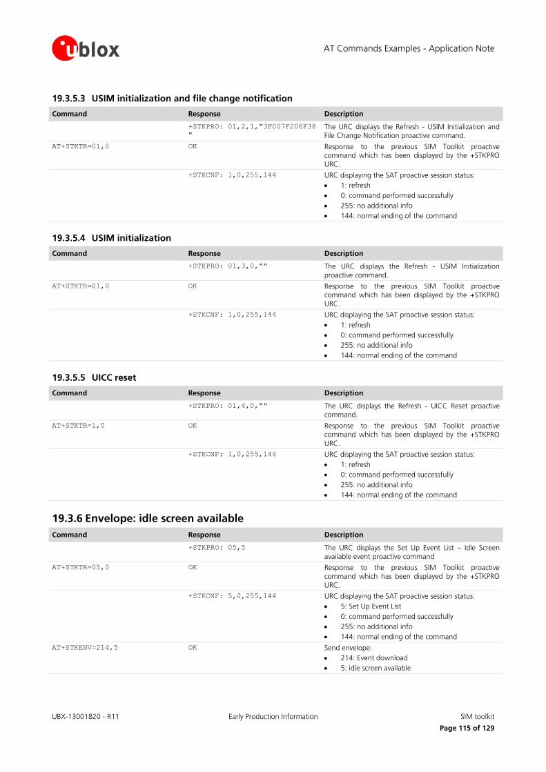
AT Commands Examples - Application Note
UBX-13001820 - R11 Early Production Information SIM toolkit
Page 115 of 129
19.3.5.3 USIM initialization and file change notification
Command Response Description
+STKPRO: 01,2,1,"3F007F206F38
"
The URC displays the Refresh - USIM Initialization and File Change Notification proactive command.
AT+STKTR=01,0 OK Response to the previous SIM Toolkit proactive command which has been displayed by the +STKPRO
URC.
+STKCNF: 1,0,255,144 URC displaying the SAT proactive session status:
1: refresh
0: command performed successfully
255: no additional info
144: normal ending of the command
19.3.5.4 USIM initialization
Command Response Description
+STKPRO: 01,3,0,"" The URC displays the Refresh - USIM Initialization
proactive command.
AT+STKTR=01,0 OK Response to the previous SIM Toolkit proactive command which has been displayed by the +STKPRO
URC.
+STKCNF: 1,0,255,144 URC displaying the SAT proactive session status:
1: refresh
0: command performed successfully
255: no additional info
144: normal ending of the command
19.3.5.5 UICC reset
Command Response Description
+STKPRO: 01,4,0,"" The URC displays the Refresh - UICC Reset proactive command.
AT+STKTR=1,0 OK Response to the previous SIM Toolkit proactive command which has been displayed by the +STKPRO
URC.
+STKCNF: 1,0,255,144 URC displaying the SAT proactive session status:
1: refresh
0: command performed successfully
255: no additional info
144: normal ending of the command
19.3.6 Envelope: idle screen available
Command Response Description
+STKPRO: 05,5 The URC displays the Set Up Event List – Idle Screen available event proactive command
AT+STKTR=05,0 OK Response to the previous SIM Toolkit proactive command which has been displayed by the +STKPRO
URC.
+STKCNF: 5,0,255,144 URC displaying the SAT proactive session status:
5: Set Up Event List
0: command performed successfully
255: no additional info
144: normal ending of the command
AT+STKENV=214,5 OK Send envelope:
214: Event download
5: idle screen available

AT Commands Examples - Application Note
UBX-13001820 - R11 Early Production Information SMS AT commands
Page 116 of 129
20 SMS AT commands
20.1 Read all messages or one single message
Command Response Description
AT+CMGF=1 OK Set the preferred message format to text mode.
AT+CPMS? +CPMS: "ME",3,300,"ME",3,300,
"ME",3,300
OK
Check which memories are active for reading, deleting, storing, sending and receiving messages.
AT+CPMS="MT" +CPMS: 5,350,3,300,3,300
OK
Set the preferred message storage to "MT" (that means SIM card + module file system) for read and
delete cases.
On SARA-G300 / SARA-G310 the supported options
are "SM" and "BM".
AT+CMGL +CMGL: 1,"REC
READ","12345",,"10/09/09,15:0
6:30+08"
Test message 1
+CMGL: 2,"STO SENT","67890",,
abcdefghijklmnopqrstuvwxyz
+CMGL: 3,"STO UNSENT","",,
Test message 2
+CMGL: 301,"REC
READ","54321",,"08/08/09,10:0
1:38+08"
Hello world
+CMGL: 302,"REC
UNREAD","9876",,"09/08/09,10:
05:40+08"
Test message 3
OK
Display the message list (both on module file system and SIM card).
AT+CMGR=301 +CMGR: "REC
READ","54321",,"08/08/09,10:0
1:38+08"
Hello world
OK
Read a single message from SIM card since the index is greater than 300 (number of SMS stored in the module file system).
AT+CMGR=2 +CMGR: "STO SENT","67890"
abcdefghijklmnopqrstuvwxyz
OK
Read a single message from the module file system since the index is lower than 300 (number of SMS stored in the module file system).
TOBY-L2 SARA-U SARA-G LISA-U LEON-G
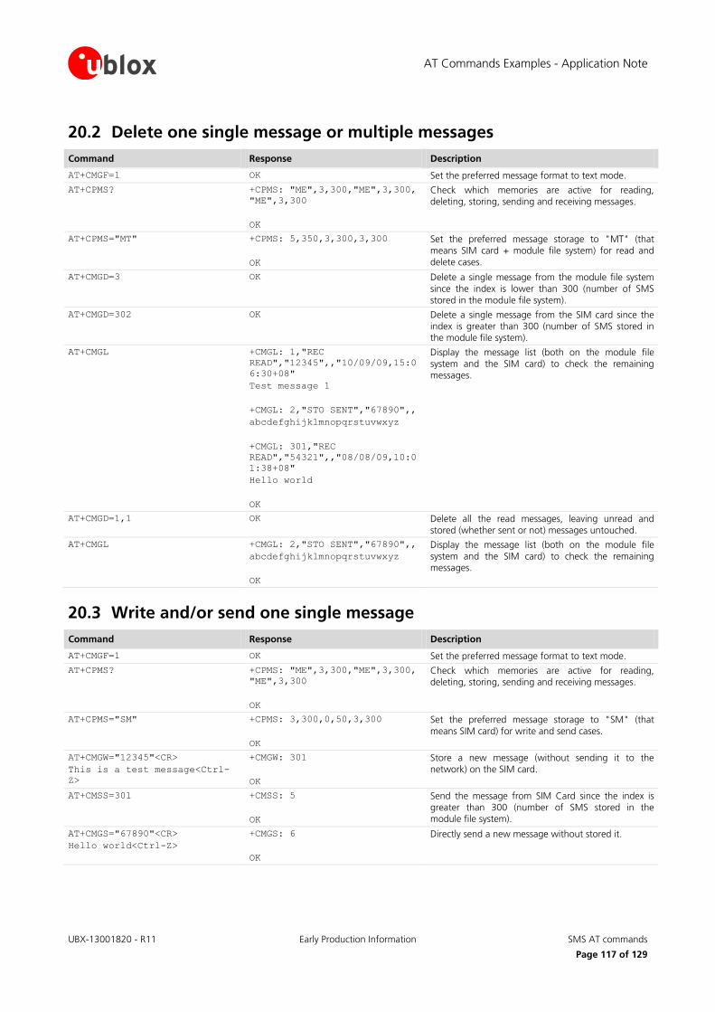
AT Commands Examples - Application Note
UBX-13001820 - R11 Early Production Information SMS AT commands
Page 117 of 129
20.2 Delete one single message or multiple messages
Command Response Description
AT+CMGF=1 OK Set the preferred message format to text mode.
AT+CPMS? +CPMS: "ME",3,300,"ME",3,300,
"ME",3,300
OK
Check which memories are active for reading, deleting, storing, sending and receiving messages.
AT+CPMS="MT" +CPMS: 5,350,3,300,3,300
OK
Set the preferred message storage to "MT" (that means SIM card + module file system) for read and
delete cases.
AT+CMGD=3 OK Delete a single message from the module file system
since the index is lower than 300 (number of SMS stored in the module file system).
AT+CMGD=302 OK Delete a single message from the SIM card since the index is greater than 300 (number of SMS stored in the module file system).
AT+CMGL +CMGL: 1,"REC
READ","12345",,"10/09/09,15:0
6:30+08"
Test message 1
+CMGL: 2,"STO SENT","67890",,
abcdefghijklmnopqrstuvwxyz
+CMGL: 301,"REC
READ","54321",,"08/08/09,10:0
1:38+08"
Hello world
OK
Display the message list (both on the module file system and the SIM card) to check the remaining messages.
AT+CMGD=1,1 OK Delete all the read messages, leaving unread and stored (whether sent or not) messages untouched.
AT+CMGL +CMGL: 2,"STO SENT","67890",,
abcdefghijklmnopqrstuvwxyz
OK
Display the message list (both on the module file
system and the SIM card) to check the remaining messages.
20.3 Write and/or send one single message
Command Response Description
AT+CMGF=1 OK Set the preferred message format to text mode.
AT+CPMS? +CPMS: "ME",3,300,"ME",3,300,
"ME",3,300
OK
Check which memories are active for reading, deleting, storing, sending and receiving messages.
AT+CPMS="SM" +CPMS: 3,300,0,50,3,300
OK
Set the preferred message storage to "SM" (that
means SIM card) for write and send cases.
AT+CMGW="12345"<CR>
This is a test message<Ctrl-
Z>
+CMGW: 301
OK
Store a new message (without sending it to the network) on the SIM card.
AT+CMSS=301 +CMSS: 5
OK
Send the message from SIM Card since the index is greater than 300 (number of SMS stored in the module file system).
AT+CMGS="67890"<CR>
Hello world<Ctrl-Z>
+CMGS: 6
OK
Directly send a new message without stored it.

AT Commands Examples - Application Note
UBX-13001820 - R11 Early Production Information SMS AT commands
Page 118 of 129
20.4 Read all messages or one single message (concatenated SMS related commands)
Not supported by LEON-G100-05S / LEON-G200-05S and previous versions.
Command Response Description
AT+CMGF=1 OK Set the preferred message format to text mode.
AT+CPMS? +CPMS: "ME",4,300,"ME",4,300,
"ME",4,300
OK
Check which memories are active for reading, deleting, storing, sending and receiving messages.
AT+CPMS="MT" +CPMS: 6,350,4,300,4,300
OK
Set the preferred message storage to "MT" (that
means SIM card + module file system) for read and delete cases.
AT+UCMGL +UCMGL: 1,"REC
READ","12345",,"10/09/09,15:0
6:30+08"
Test message 1
+UCMGL: 2,"STO
SENT","67890",,,1,2,0,201
While some observers suggest
the new plan shows
government's determination to
cool down the property
market, several developers
disagree, saying prices a
+UCMGL: 3,"STO
SENT","67890",,,2,2,0,201
re determined by the economy.
+UCMGL: 4,"STO UNSENT","",,
Test message 2
+UCMGL: 301,"REC
READ","54321",,"15/10/09,13:0
1:00+08",1,2,8,3840
The government will study
whether the former chief
executive of the West Kowloon
Cultural District authority,
Graham Sheffield, has
breached his contrac
+UCMGL: 302,"REC
READ","54321",,"15/10/09,13:0
2:40+08",2,2,8,3840
t by taking up a new position
at the British Council in
London.
OK
Display the message list (both on the module file system and the SIM card).
The messages of index 2 and 3 (stored on module file system) are the two parts of an "8-bit reference
number" type concatenated SMS (they have the same reference number = 201).
The messages of index 301 and 302 (stored on SIM card) are the two parts of an "16-bit reference
number" type concatenated SMS (they have the same reference number = 3840).
Also the +CMGL command shows all the
SMS, parts of concatenated messages included, but there are no additional
information about which of them are linked together.
LEON-G
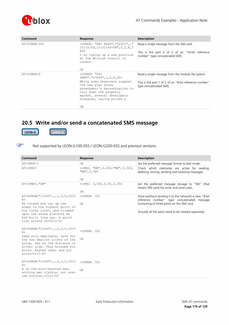
AT Commands Examples - Application Note
UBX-13001820 - R11 Early Production Information SMS AT commands
Page 119 of 129
Command Response Description
AT+UCMGR=302 +UCMGR: "REC READ","54321",,"
15/10/09,13:02:40+08",2,2,8,3
840
t by taking up a new position
at the British Council in
London.
OK
Read a single message from the SIM card.
This is the part 2 of 2 of an "16-bit reference number" type concatenated SMS.
AT+UCMGR=2 +UCMGR: "STO
SENT","67890",1,2,0,201
While some observers suggest
the new plan shows
government's determination to
cool down the property
market, several developers
disagree, saying prices a
OK
Read a single message from the module file system.
This is the part 1 of 2 of an "8-bit reference number" type concatenated SMS.
20.5 Write and/or send a concatenated SMS message
Not supported by LEON-G100-05S / LEON-G200-05S and previous versions.
Command Response Description
AT+CMGF=1 OK Set the preferred message format to text mode.
AT+CPMS? +CPMS: "ME",3,300,"ME",3,300,
"ME",3,300
OK
Check which memories are active for reading,
deleting, storing, sending and receiving messages.
AT+CPMS=,"SM" +CPMS: 3,300,0,50,3,300
OK
Set the preferred message storage to "SM" (that means SIM card) for write and send cases.
AT+UCMGW="12345",,,1,3,0,25<C
R>
He turned and ran up the
steps to the highest point of
his rocky islet, and climbed
upon the stone platform he
had built long ago. A quick
look around sh<Ctrl-Z>
AT+UCMGW="12345",,,2,3,0,25<C
R>
owed only emptiness, save for
the two smaller islets of the
group, dim in the distance on
either side. They bounded his
world. Beyond them, and all
aroun<Ctrl-Z>
AT+UCMGW="12345",,,3,3,0,25<C
R>
d in the mist-haunted sea,
nothing was visible, not even
the horizon.<Ctrl-Z>
+UCMGW: 301
OK
+UCMGW: 302
OK
+UCMGW: 303
OK
Store (without sending it to the network) a new "8-bit reference number" type concatenated message (consisting of three parts) on the SIM card.
Actually all the parts need to be created separately.
SARA-G LEON-G
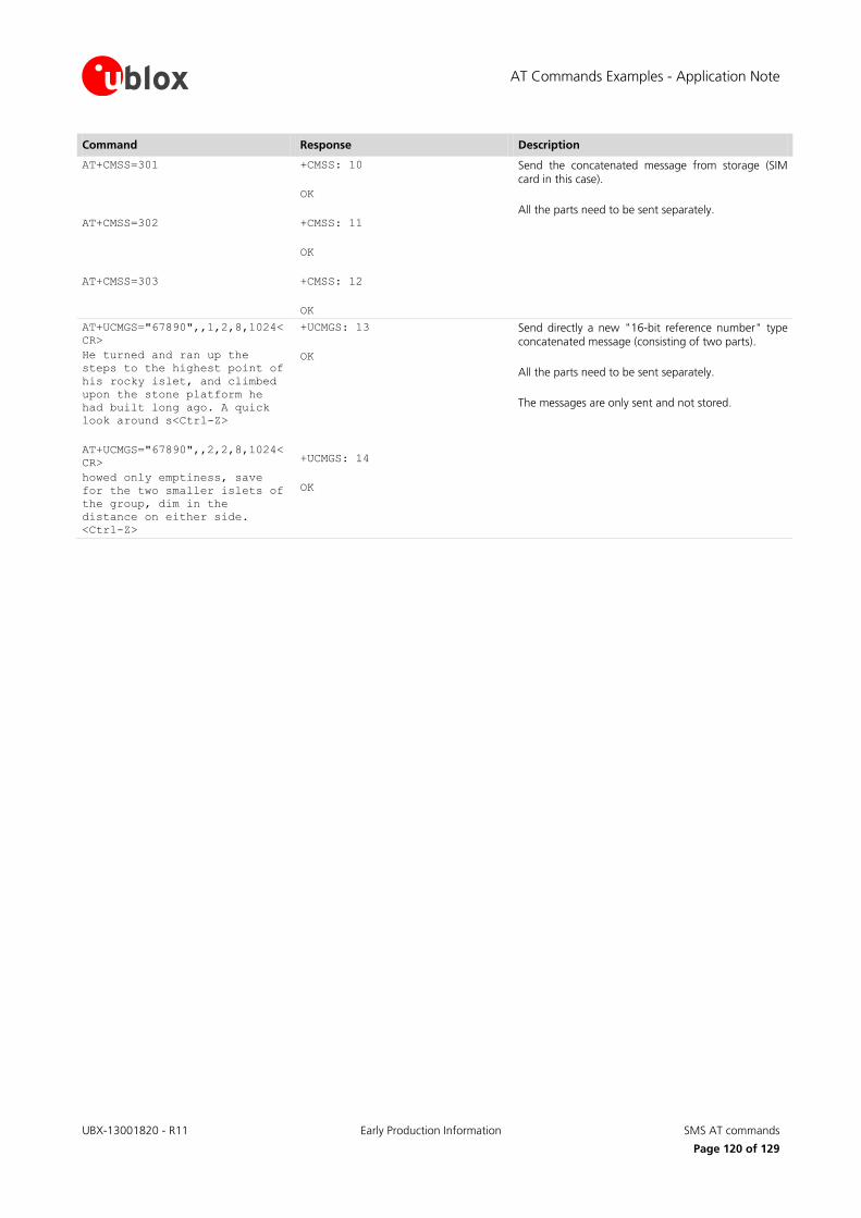
AT Commands Examples - Application Note
UBX-13001820 - R11 Early Production Information SMS AT commands
Page 120 of 129
Command Response Description
AT+CMSS=301
AT+CMSS=302
AT+CMSS=303
+CMSS: 10
OK
+CMSS: 11
OK
+CMSS: 12
OK
Send the concatenated message from storage (SIM card in this case).
All the parts need to be sent separately.
AT+UCMGS="67890",,1,2,8,1024<
CR>
He turned and ran up the
steps to the highest point of
his rocky islet, and climbed
upon the stone platform he
had built long ago. A quick
look around s<Ctrl-Z>
AT+UCMGS="67890",,2,2,8,1024<
CR>
howed only emptiness, save
for the two smaller islets of
the group, dim in the
distance on either side.
<Ctrl-Z>
+UCMGS: 13
OK
+UCMGS: 14
OK
Send directly a new "16-bit reference number" type concatenated message (consisting of two parts).
All the parts need to be sent separately.
The messages are only sent and not stored.
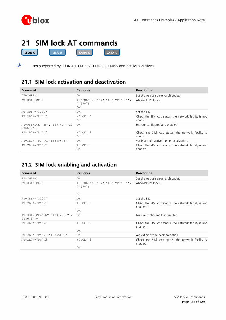
AT Commands Examples - Application Note
UBX-13001820 - R11 Early Production Information SIM lock AT commands
Page 121 of 129
21 SIM lock AT commands
Not supported by LEON-G100-05S / LEON-G200-05S and previous versions.
21.1 SIM lock activation and deactivation
Command Response Description
AT+CMEE=2 OK Set the verbose error result codes.
AT+USIMLCK=? +USIMLCK: ("PN","PU","PS"),"","
",(0-1)
OK
Allowed SIM locks.
AT+CPIN="1234" OK Set the PIN.
AT+CLCK="PN",2 +CLCK: 0
OK
Check the SIM lock status; the network facility is not
enabled.
AT+USIMLCK="PN","123.45","12
345678",1
OK Feature configured and enabled.
AT+CLCK="PN",2 +CLCK: 1
OK
Check the SIM lock status; the network facility is enabled.
AT+CLCK="PN",0,"12345678" OK Verify and de-active the personalization.
AT+CLCK="PN",2 +CLCK: 0
OK
Check the SIM lock status; the network facility is not enabled.
21.2 SIM lock enabling and activation
Command Response Description
AT+CMEE=2 OK Set the verbose error result codes.
AT+USIMLCK=? +USIMLCK: ("PN","PU","PS"),"","
",(0-1)
OK
Allowed SIM locks.
AT+CPIN="1234" OK Set the PIN.
AT+CLCK="PN",2 +CLCK: 0
OK
Check the SIM lock status; the network facility is not enabled.
AT+USIMLCK="PN","123.45","12
345678",0
OK Feature configured but disabled.
AT+CLCK="PN",2 +CLCK: 0
OK
Check the SIM lock status; the network facility is not enabled.
AT+CLCK="PN",1,"12345678" OK Activation of the personalization.
AT+CLCK="PN",2 +CLCK: 1
OK
Check the SIM lock status; the network facility is enabled.
SARA-U SARA-G LISA-U LEON-G

AT Commands Examples - Application Note
UBX-13001820 - R11 Early Production Information SIM Access Profile (SAP) AT commands
Page 122 of 129
22 SIM Access Profile (SAP) AT commands
Not supported by LISA-U1 series or by LISA-U200-00S versions.
SAP AT commands enable the u-blox modules to connect to an SAP server and exchange data with the SIM provided by the server, as if it is locally attached to the u-blox cellular module. Once the connection to an SAP server is established and negotiated, the u-blox module performs a detach operation from the local SIM in the SIM card holder connected to the module, followed by an attach operation to the remote SIM. From this time on, any operation of the u-blox module is routed to the remotely attached SIM. With the SAP deactivation, the module performs a detach operation from the remote SIM followed by an attach operation to the local one (if present).
For more details on SAP implementation, see the LISA-U Series System Integration Manual [6] and SARA-G / SARA-U Series System Integration Manual [7].
22.1 SAP activation
Command Response Description
AT+CMEE=2 OK Set the verbose error result codes.
AT+USAPIND=1 OK Enable the URC generation for the SAP mode status
change indication and remote SIM status change indication.
Enable the "SIM card detection" and "SIM hot
insertion/removal" functions via AT commands (for more details see u-blox AT Commands Manual [1],
+UGPIOC, +UDCONF=50 AT commands), to generate the URCs for local insertion/removal actions of the
local SIM.
AT+USAPMODE=? +USAPMODE: (0-1),0,(0-65535)
OK
Allowed the SAP modes and parameters.
AT+USAPMODE=1 OK Start the SAP negotiation with server.
+UUSAPMODE: 1 URC signaling SAP client connected to server.
+UUSAPREMOTE: 1 URC signaling remote SIM present.
The local SIM (if present) is detached. The remote SIM is attached: any following operations are routed to
the attached remote SIM.
AT+USAPMODE? +USAPMODE: 1
OK
The SAP client mode is active.
AT+CPIN? +CPIN: SIM PIN Check the PIN of the remote SIM.
AT+CPIN="1234" OK Set the PIN of the remote SIM.
AT+CPIN? +CPIN: READY
OK
Remote SIM authenticated and ready to use.
AT+COPS? +COPS: 0,0,"vodafone IT",0
OK
Network registration status with attached remote SIM.
ATD+3933812345678; OK Place a voice call using attached the remote SIM.
SARA-U LISA-U

AT Commands Examples - Application Note
UBX-13001820 - R11 Early Production Information SIM Access Profile (SAP) AT commands
Page 123 of 129
Command Response Description
+UUSAPLOCAL: 1 A local SIM is inserted in the SIM card holder connected to the module. Because a SAP session is
running, the module operations are routed to the attached remote SIM.
+UUSAPLOCAL: 0 The local SIM is removed from the SIM card holder connected to the module. Because a SAP session is running, the module operations are routed to the
attached remote SIM.
22.2 SAP deactivation
Command Response Description
AT+CMEE=2 OK Set the verbose error result codes.
AT+USAPIND=1 OK Enable the URC generation for the SAP mode status
change indication.
AT+USAPMODE=0 OK Stop the SAP connection with server.
+UUSAPMODE: 0 A URC indicates the SAP client is disconnected from server.
Remote SIM is detached; the local SIM (if present) is
attached: any following operations are routed to the attached local SIM.
AT+USAPMODE? +USAPMODE: 0
OK
The SAP connection is terminated.
AT+CPIN? +CME ERROR: SIM not inserted Local SIM not present.
AT+COPS? +COPS: 0
OK
Module not registered to the network.
ATD+3933812345678; +CME ERROR: SIM not inserted Unable to place call because the local SIM not present.
AT+USAPIND=0 OK Disable the URC generation for the SAP mode status change indication.
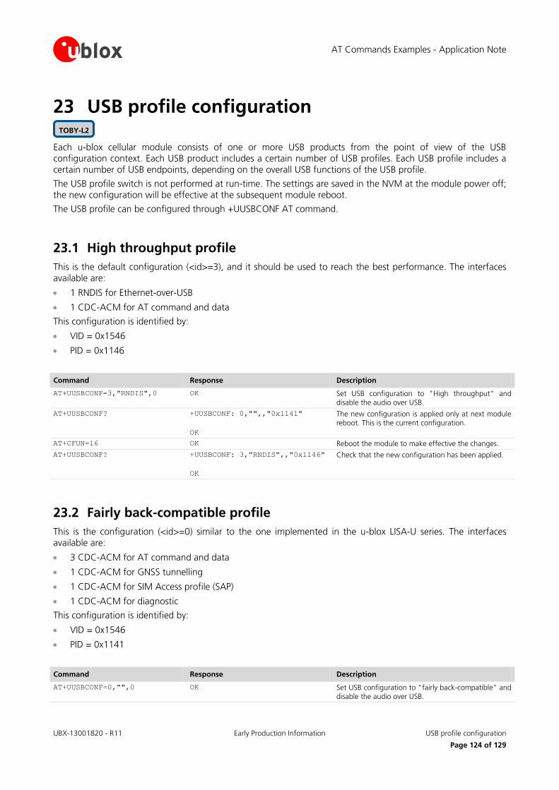
AT Commands Examples - Application Note
UBX-13001820 - R11 Early Production Information USB profile configuration
Page 124 of 129
23 USB profile configuration
Each u-blox cellular module consists of one or more USB products from the point of view of the USB configuration context. Each USB product includes a certain number of USB profiles. Each USB profile includes a certain number of USB endpoints, depending on the overall USB functions of the USB profile.
The USB profile switch is not performed at run-time. The settings are saved in the NVM at the module power off; the new configuration will be effective at the subsequent module reboot.
The USB profile can be configured through +UUSBCONF AT command.
23.1 High throughput profile
This is the default configuration (<id>=3), and it should be used to reach the best performance. The interfaces available are:
1 RNDIS for Ethernet-over-USB
1 CDC-ACM for AT command and data
This configuration is identified by:
VID = 0x1546
PID = 0x1146
Command Response Description
AT+UUSBCONF=3,"RNDIS",0 OK Set USB configuration to "High throughput" and disable the audio over USB.
AT+UUSBCONF? +UUSBCONF: 0,"",,"0x1141"
OK
The new configuration is applied only at next module reboot. This is the current configuration.
AT+CFUN=16 OK Reboot the module to make effective the changes.
AT+UUSBCONF? +UUSBCONF: 3,"RNDIS",,"0x1146"
OK
Check that the new configuration has been applied.
23.2 Fairly back-compatible profile
This is the configuration (<id>=0) similar to the one implemented in the u-blox LISA-U series. The interfaces available are:
3 CDC-ACM for AT command and data
1 CDC-ACM for GNSS tunnelling
1 CDC-ACM for SIM Access profile (SAP)
1 CDC-ACM for diagnostic
This configuration is identified by:
VID = 0x1546
PID = 0x1141
Command Response Description
AT+UUSBCONF=0,"",0 OK Set USB configuration to "fairly back-compatible" and disable the audio over USB.
TOBY-L2

AT Commands Examples - Application Note
UBX-13001820 - R11 Early Production Information
Page 125 of 129
Command Response Description
AT+UUSBCONF? +UUSBCONF: 3,"RNDIS",,"0x1146"
OK
The new configuration is applied only at next module reboot. This is the current configuration.
AT+CFUN=16 OK Reboot the module to make effective the changes.
AT+UUSBCONF? +UUSBCONF: 0,"",,"0x1141"
OK
Check that the new configuration has been applied.
23.3 Low/Medium throughput profile
In this configuration (<id>=2) the presence of several USB functions limits the reachable data transfer throughput. The interfaces available are:
3 CDC-ACM for AT command and data
1 CDC-ECM for Ethernet-over-USB
This configuration is identified by:
VID = 0x1546
PID = 0x1143
Command Response Description
AT+UUSBCONF=2,"ECM",0 OK Set USB configuration to "low/medium throughput" and disable the audio over USB.
AT+UUSBCONF? +UUSBCONF: 0,"",,"0x1141"
OK
The new configuration is applied only at next module
reboot. This the current configuration.
AT+CFUN=16 OK Reboot the module to make effective the changes.
AT+UUSBCONF? +UUSBCONF: 2,"ECM",,"0x1143"
OK
Check that the new configuration has been applied.

AT Commands Examples - Application Note
UBX-13001820 - R11 Early Production Information Appendix
Page 126 of 129
Appendix
A List of acronyms Abbreviation / Term Explanation / Definition
3GPP 3rd Generation Partnership Project
ADC Analog to Digital Converter
APN Access Point Name
AT AT Command Interpreter Software Subsystem, or attention
CI Cell Identity
CTS Clear To Send
DLC Data Link Connection
DM Device Management
DNS Domain Name System
DTE Data Terminal Equipment
DUT Device Under Test
EDGE Enhanced Data rates for GSM Evolution
EHPLMN Equivalent Home PLMN
EPLMN Equivalent PLMN
EPS Evolved Packet System
FTP File Transfer Protocol
GNSS Global Navigation Satellite System
GPIO General Purpose Input Output
GPRS General Packet Radio Service
GSM Global System for Mobile Communication
HPLMN Home PLMN
HSDPA High Speed Downlink Packet Access
HTTP HyperText Transfer Protocol
I2C Inter-Integrated Circuit
IMEI International Mobile Equipment Identity
IMSI International Mobile Station Identity
IP Internet Protocol
LAC Location Area Code
MCC Mobile Country Code
MNC Mobile Network Code
MT Mobile Terminal
NVM Non Volatile Memory
ODIS OMA-DM IMEI Sync
OMA-DM Open Mobile Alliance Device Management
PDP Parallel Data Processing

AT Commands Examples - Application Note
UBX-13001820 - R11 Early Production Information Appendix
Page 127 of 129
Abbreviation / Term Explanation / Definition
PIN Personal Identification Number
PLMN Public Land Mobile Network
RAT Radio Access Technology
RTS Request To Send
SAT SIM Application Toolkit
SIM Subscriber Identification Module
SV Satellite in View
SMTP Simple Mail Transfer Protocol
TA Timing Advance
TCP Transmission Control Protocol
TTFF Time To First Fix
UDP User Datagram Protocol
UMTS Universal Mobile Telecommunications System
URC Unsolicited Result Code
URL Uniform Resource Locator
VPLMN Visited PLMN
WCDMA Wideband CODE Division Multiple Access
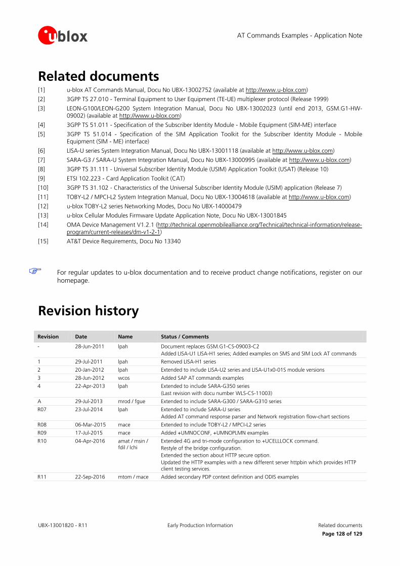
AT Commands Examples - Application Note
UBX-13001820 - R11 Early Production Information Related documents
Page 128 of 129
Related documents [1] u-blox AT Commands Manual, Docu No UBX-13002752 (available at http://www.u-blox.com)
[2] 3GPP TS 27.010 - Terminal Equipment to User Equipment (TE-UE) multiplexer protocol (Release 1999)
[3] LEON-G100/LEON-G200 System Integration Manual, Docu No UBX-13002023 (until end 2013, GSM.G1-HW-09002) (available at http://www.u-blox.com)
[4] 3GPP TS 51.011 - Specification of the Subscriber Identity Module - Mobile Equipment (SIM-ME) interface
[5] 3GPP TS 51.014 - Specification of the SIM Application Toolkit for the Subscriber Identity Module - Mobile Equipment (SIM - ME) interface)
[6] LISA-U series System Integration Manual, Docu No UBX-13001118 (available at http://www.u-blox.com)
[7] SARA-G3 / SARA-U System Integration Manual, Docu No UBX-13000995 (available at http://www.u-blox.com)
[8] 3GPP TS 31.111 - Universal Subscriber Identity Module (USIM) Application Toolkit (USAT) (Release 10)
[9] ETSI 102.223 - Card Application Toolkit (CAT)
[10] 3GPP TS 31.102 - Characteristics of the Universal Subscriber Identity Module (USIM) application (Release 7)
[11] TOBY-L2 / MPCI-L2 System Integration Manual, Docu No UBX-13004618 (available at http://www.u-blox.com)
[12] u-blox TOBY-L2 series Networking Modes, Docu No UBX-14000479
[13] u-blox Cellular Modules Firmware Update Application Note, Docu No UBX-13001845
[14] OMA Device Management V1.2.1 (http://technical.openmobilealliance.org/Technical/technical-information/release-program/current-releases/dm-v1-2-1)
[15] AT&T Device Requirements, Docu No 13340
For regular updates to u-blox documentation and to receive product change notifications, register on our homepage.
Revision history
Revision Date Name Status / Comments
- 28-Jun-2011 lpah Document replaces GSM.G1-CS-09003-C2
Added LISA-U1 LISA-H1 series; Added examples on SMS and SIM Lock AT commands
1 29-Jul-2011 lpah Removed LISA-H1 series
2 20-Jan-2012 lpah Extended to include LISA-U2 series and LISA-U1x0-01S module versions
3 28-Jun-2012 wcos Added SAP AT commands examples
4 22-Apr-2013 lpah Extended to include SARA-G350 series
(Last revision with docu number WLS-CS-11003)
A 29-Jul-2013 mrod / fgue Extended to include SARA-G300 / SARA-G310 series
R07 23-Jul-2014 lpah Extended to include SARA-U series
Added AT command response parser and Network registration flow-chart sections
R08 06-Mar-2015 mace Extended to include TOBY-L2 / MPCI-L2 series
R09 17-Jul-2015 mace Added +UMNOCONF, +UMNOPLMN examples
R10 04-Apr-2016 amat / msin / fdil / lchi
Extended 4G and tri-mode configuration to +UCELLLOCK command.
Restyle of the bridge configuration.
Extended the section about HTTP secure option.
Updated the HTTP examples with a new different server httpbin which provides HTTP
client testing services.
R11 22-Sep-2016 mtom / mace Added secondary PDP context definition and ODIS examples

AT Commands Examples - Application Note
UBX-13001820 - R11 Early Production Information Contact
Page 129 of 129
Contact For complete contact information visit us at www.u-blox.com
u-blox Offices
North, Central and South America
u-blox America, Inc.
Phone: +1 703 483 3180 E-mail: [email protected]
Regional Office West Coast:
Phone: +1 408 573 3640 E-mail: [email protected]
Technical Support:
Phone: +1 703 483 3185 E-mail: [email protected]
Headquarters Europe, Middle East, Africa
u-blox AG
Phone: +41 44 722 74 44 E-mail: [email protected] Support: [email protected]
Asia, Australia, Pacific
u-blox Singapore Pte. Ltd.
Phone: +65 6734 3811 E-mail: [email protected] Support: [email protected]
Regional Office Australia:
Phone: +61 2 8448 2016 E-mail: [email protected] Support: [email protected]
Regional Office China (Beijing):
Phone: +86 10 68 133 545 E-mail: [email protected] Support: [email protected]
Regional Office China (Chongqing):
Phone: +86 23 6815 1588 E-mail: [email protected] Support: [email protected]
Regional Office China (Shanghai):
Phone: +86 21 6090 4832 E-mail: [email protected] Support: [email protected]
Regional Office China (Shenzhen):
Phone: +86 755 8627 1083 E-mail: [email protected] Support: [email protected]
Regional Office India:
Phone: +91 80 4050 9200 E-mail: [email protected] Support: [email protected]
Regional Office Japan (Osaka):
Phone: +81 6 6941 3660 E-mail: [email protected] Support: [email protected]
Regional Office Japan (Tokyo):
Phone: +81 3 5775 3850 E-mail: [email protected] Support: [email protected]
Regional Office Korea:
Phone: +82 2 542 0861 E-mail: [email protected] Support: [email protected]
Regional Office Taiwan:
Phone: +886 2 2657 1090 E-mail: [email protected] Support: [email protected]