asynchronous design: introduction to principles and models
TRANSCRIPT

Asynchronous Design: Introduction to Principles and Models
Alex Yakovlev
Newcastle University
Newcastle upon Tyne, U.K.

• Six Asynchronous Design Principles: – Asynchronous Handshaking – Delay-insensitive Encoding – Completion Detection – Causal Acknowledgement – Full Indication and Early Evaluation – Time Comparison
• Pros and Cons • (Some of the) Models, Techniques and Tools for
Asynchronous Design • Asynchronous control logic synthesis from Signal
Transition Graphs
Outline
1

Asynchronous Behaviour
• Synchronous vs Asynchronous behaviour in general terms, examples:
– Orchestra playing with vs without a conductor
– Party of people having a set menu vs a la carte
• Synchronous means all parts of the system acting globally in tact, even if some or all part ‘do nothing’
• Asynchronous means parts of the system act on demand rather than on global clock tick
• Acting in computation and communication is, generally, changing the system state
• Synchrony and Asynchrony can be in found in CPUs, Memory, Communications, SoCs, NoCs etc.
2

Key Principles of Asynchronous Design
• Asynchronous handshaking
• Delay-insensitive encoding
• Completion detection
• Causal acknowledgment (aka indication or indicatability)
• Strong and weak causality (full indication and early evaluation)
• “Time comparison” (synchronisation, arbitration)
3

Why and what is handshaking?
Mutual Synchronisation is via Handshake
4

Synchronous clocking
How we think
What we design
5

Asynchronous handshaking
What we
design
How we think
Handshake latch Handshake CL ”Channel” or ”Link”
6

Handshake Signalling Protocols
Level Signalling (RTZ or 4-phase)
Transition Signalling (NRZ or 2-phase)
One cycle
req
ack
req
One cycle
req
ack
One cycle
7
ack
(a) (b)

Why and what is delay-insensitive coding?
Data Token = (Data Value, Validity Flag)
8
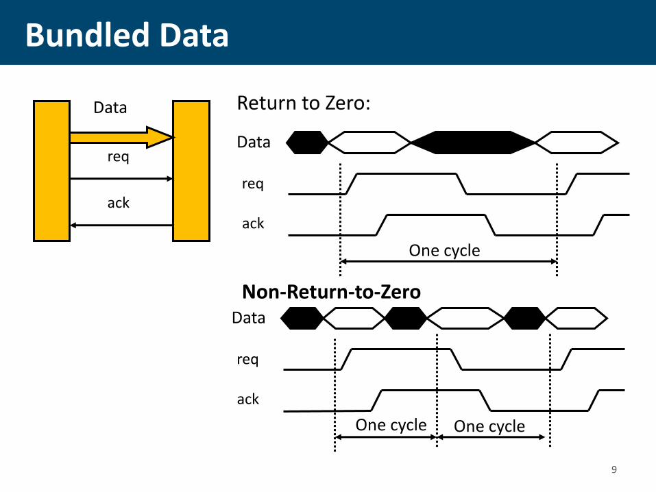
Bundled Data
req
ack
Data
One cycle
req
ack
Data
Return to Zero:
Non-Return-to-Zero
One cycle
req
ack
Data
One cycle
9

DI encoded data (Dual-Rail)
ack
Data.0
One cycle
Data.1
ack
Data.0 Data.1
Logical 1 Logical 0
One cycle
NULL (spacer) NULL
cycle
Data.1
ack
Data.0 Logical 1
Logical 0
cycle cycle
Logical 1 Logical 1
cycle
RTZ:
NRZ: NRZ coding leads to complex logic implementation; special ways to track odd and even phases and logic values are needed, such as LEDR 10

DI codes (1-of-n and m-of-n)
• 1-of-4:
– 0001=> 00, 0010=>01, 0100=>10, 1000=>11
• 2-of-4:
– 1100, 1010, 1001, 0110, 0101, 0011 – total 6 combinations (cf. 2-bit dual-rail – 4 comb.)
• 3-of-6:
– 111000, 110100, …, 000111 – total 20 combinations (can encode 4 bits + 4 control tokens)
• 2-of-7:
– 1100000, 1010000, …, 0000011 – total 21 combinations (4 bits + 5 control tokens)
11

Why and what is completion detection?
Signalling that the Transients are over
12

Bundled-data logic blocks
Single-rail logic
• • •
• • •
delay start done
Conventional logic + matched delay
Completion is implicit: by done signal
The delay must scale with the worst case delay path, So … not really self-timed
13

True completion detection
Dual-rail logic
• • •
• • •
C done
Completion detection tree
Completion detection for one dual-rail bit
C
• • •
Multi-input C-element
14

The Muller C element
C
A
B Z
A B Z+
0 0 0
0 1 Z
1 0 Z
1 1 1
Vdd
Gnd
A
A
A
A B
B
B
B
Z
Z
Z
[van Berkel 91]
Static Logic
Implementation
C
15

C-element: Other implementations
A
A
B
B
Gnd
Vdd
Z
A
A
B
B
Gnd
Vdd
Z
Weak inverter
Quasi-Static Dynamic

Why and what is causal acknowledgment?
Every signal event must be acknowledged by another event
17

Causal acknowledgment
a(0)
b(0) c(0)
x1 (1)
x2 (1)
x3(1)
C-element implementation using simple gates
a+
b+
x1- c+
x2-
x1+
c-
x3-
a+
b+
a-
b-
c+ c-
a-
b- x2+
x3+
Unack’ed transitions x2- and x3- may cause a hazard on output c
However, under Fundamental Mode (slow environment) the circuit is safe
18

Principle of causal acknowledgement
a(0)
b(0)
c(0) x1(1)
x4(0)
x2(0)
x3(1)
a+
b+
a-
b-
c+ c-
C-element implementation using simple gates
a-
b-
x4- x3+ x2- c-
a+
b+
x1- x2+ x3- x1+ c+
x4+
Each transition is causally ack’ed, hence no hazards can appear
19

Why and what are strong and weak causality ?
Degree of necessity of precedence of some events for other events
20

Strong Causality
• Petri net transitions synchronising as rendez-vous
A
C
B
• Logic circuits: Muller C-element (in 0-1 and 1-0 transitions), AND gate (in 0-1 transitions), OR gate (in 1-0 tranisitions)
A B C+ 0 0 0 0 1 C 1 0 C 1 1 1
Strong precedence
21
A
B C C
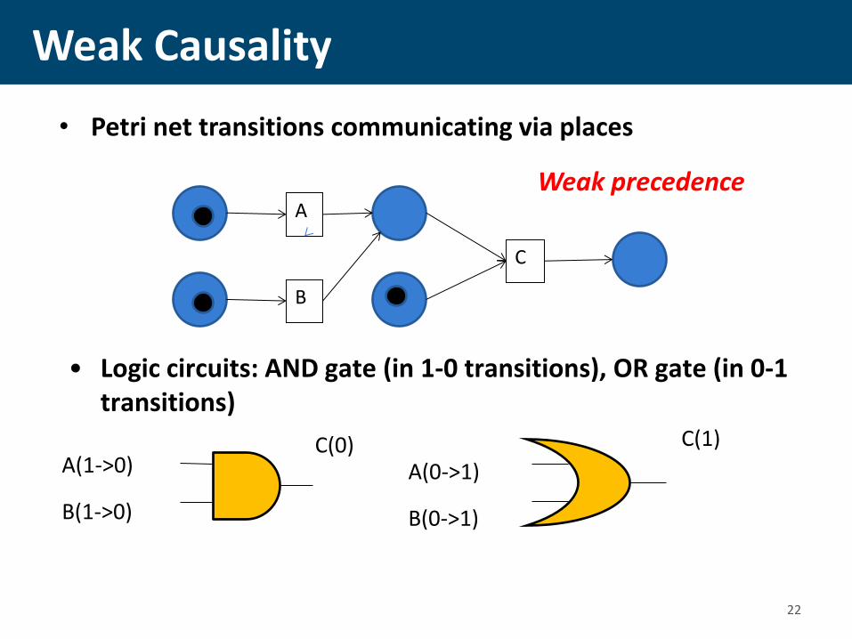
Weak Causality
• Petri net transitions communicating via places
A
C
B
• Logic circuits: AND gate (in 1-0 transitions), OR gate (in 0-1 transitions)
A(1->0)
B(1->0)
C(0) A(0->1)
B(0->1)
C(1)
Weak precedence
22

Full indication versus Early Evaluation
A.t
A.f
B.t
B.f
C.t
C.f
Dual-rail AND gate with “early propagation”
Allows outputs to be produced from NULL to Codeword only when some (required) inputs have transitioned from NULL to Codeword (similar for Codeword to NULL)
C
C
C
C
B.t
A.t C.t
C.f
A.t
A.f
A.f
B.f
B.t
B.f
Dual-rail AND gate with full input acknowledgement
23

Why and what is timing comparison?
Telling if some event happened before another event
24

Synchronizers and arbiters
Your system
Input
Your system
Input 1
Input 2
Synchronizer
Decides which clock cycle to use for the
input data
Asynchronous arbiter
Decides the order of inputs
25

Metastability is....
Not being able to decide…
Q
Q
Clock
D
tin
tin -> 0
D
Clock
Request
Processor Clock
Set-up time violated
26

Typical responses
• We assume all starting points are equally probable • Most are a long way from the “balance point” • A few are very close and take a long time to resolve
Clock
Q Output
Clock
D Q #1
Q Trigger
27

Synchronizer
• t is time allowed for the Q to change between CLK a and CLK b
• is the recovery time constant, usually the gain-bandwidth of the circuit
• Tw is the “metastability window” (aperture around clock edge in which the capture of data edge causes a delay that is greater than normal propagation delay of the FF)
• and Tw depend on the circuit
• We assume that all values of tin are equally probable
D Q D Q
CLK a
VALID
#1 #2
dcw
t
ffT
eMTBF
..
/
CLK b
28

Two-way arbiter (Mutual exclusion element)
req1
req2
ack2
ack1
(0)
(0)
(1)
(1)
(0)
(0)
Basic arbitration element: Mutex (due to Seitz, 1979)
An asynchronous data latch with metastability resolver can be built similarly
Metastability resolver
29

• Understanding metastability is becoming very important as analogue and digital domains get closer, and timing uncertainty and PVT variations increase
• Arbitration and synchronization are increasing their importance due to many-core, timing domains, NoCs, GALS
• Design automation for metastability and synchronization is turning from research to practice (Blendix)
Importance of Timing Comparison
30

Pros…
• People have always been excited by asynchronous design, and motivated by:
– Higher performance (work on average not worst case delays)
– Lower power consumption (automatic fine-grain “clock” gating;
automatic instantaneous stand-by at arbitrary granularity in time and function; distributed localized control; more architectural options/freedom; more freedom to scale the supply voltage)
– Modularity (Timing is at interfaces)
– Lower EMI and smoother Idd (the local “clocks” tend to tick at
random points in time)
– Low sensitivity to PVT variations (timing based on matched delays or even delay insensitive)
– Secure chips (white noise current spectrum)
– Plus, … a lot of scope and fun for research (there are many unexplored paths in this forest!)
31
• So why have async designers been often “crucified” in the past?
– Overhead (area, speed, power)
• Control and handshaking
• Dual-rail and completion detection costs
– Hard to design • yes and no, ... It’s different – there are very many styles and variants
to go and one can easily get confused which is better
– Very few **practical** CAD tools (but many academic tools)
• Tools are quite specific to particular design styles and design niches; hence don’ t cover the whole spectrum
• Complexity of timing and performance models
• Difficulty with sign-off (for particular frequency requirements)
• ... But the situation is improving
– Hard to Test • Possible, but not as mature as sync
… Cons
32
Models and techniques for design
33

Models and techniques for asynchronous design
• Models:
– Delay model (inertial, pure, gate delay, wire delay, bounded and unbounded delays)
– Models of environment (fundamental mode, input-output)
– Models of switching behaviour (state-based, event-based, hybrid)
• RTL level:
– Data and control paths separate (data flow graphs, FSMs, Signal Transition Graphs, Synchronised Transitions)
– Pipeline based (Combinational logic plus registers and latch controllers, e.g. micropipelines, gate-level pipelining)
– Process-based (CSP-like, Balsa, Haste, Communicating Hardware Processes)
• High-level models
– Flow graphs (Marked graphs, extended MGs), Petri nets, Markov Chains
– Behavioural HDLs (C, SystemC) 34
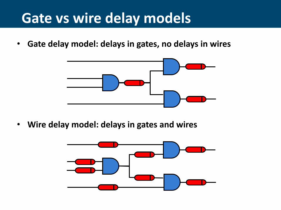
Gate vs wire delay models
• Gate delay model: delays in gates, no delays in wires
• Wire delay model: delays in gates and wires

Delay models for async. circuits
• Bounded delays (BD): realistic for gates and wires.
– Technology mapping is easy, verification is difficult
• Speed independent (SI): Unbounded (pessimistic) delays for gates and “negligible” (optimistic) delays for wires.
– Technology mapping is more difficult, verification is easy
• Delay insensitive (DI): Unbounded (pessimistic) delays for gates and wires.
– DI class (built out of basic gates) is almost empty
• Quasi-delay insensitive (QDI): Delay insensitive except for critical wire forks (isochronic forks).
– In practice it is the same as speed independent
BD
SI QDI
DI
36

Control Logic
• Control specification based on Petri nets (Signal Transition graphs)
37
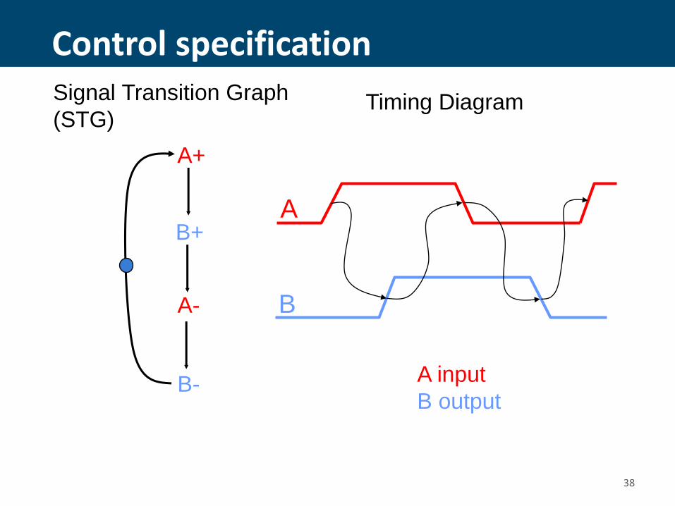
Control specification
A+
B+
A-
B-
A
B
A input
B output
Timing Diagram Signal Transition Graph
(STG)
38
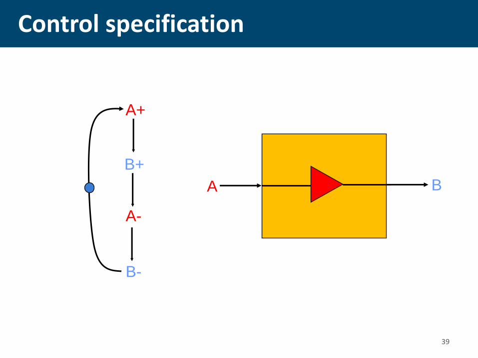
Control specification
A+
B+
A-
B-
A B
39

Control specification
A+
B-
A-
B+
A B
40

Control specification
A+
C-
A-
C+ A
C
B+
B- B
C C
41

Control specification
A+
C-
A-
C+
B+
B-
C C C
A
B
42

43
VME bus example using Petri nets
Device
LDS
LDTACK
D
DSr
DSw
DTACK
VME Bus Controller
Data
Transceiver
Bus DSr
LDS
LDTACK
D
DTACK
Read Cycle

44
STG for the READ cycle
LDS+ LDTACK+ D+ DTACK+ DSr- D-
DTACK-
LDS- LDTACK-
DSr+
LDS
LDTACK
D
DSr
DTACK
VME Bus Controller

Choice: Read and Write cycles
DSr+
LDS+
LDTACK+
D+
DTACK+
DSr-
D-
DTACK-
LDS-
LDTACK-
DSw+
D+
LDS+
LDTACK+
D-
DTACK+
DSw-
DTACK-
LDS-
LDTACK-
45

Choice: Read and Write cycles
DTACK-
DSr+
LDS+
LDTACK+
D+
DTACK+
DSr-
D-
LDS-
LDTACK-
DSw+
D+
LDS+
LDTACK+
D-
DTACK+
DSw- 46
Workcraft tool
• Workcraft is a software package for graphical edit, analysis, synthesis and visualisation of asynchronous circuit behaviour
• Petrify plus a few other tools are part of it as plug-ins
• It is based in Java tools
• Can be downloaded from http://workcraft.org/wiki/doku.php?id=download
• And installed in 10 minutes.
• There is a simple to use tutorial for that
47

Some references • General Async Design: J. Sparsø and S.B. Furber, editors. Principles of
Asynchronous Circuit Design, Kluwer Academic Publishers, 2001. (electronic
version of a tutorial based on this book can be found on:
http://www2.imm.dtu.dk/pubdb/views/edoc_download.php/855/pdf/imm855.p
df
• Async Control Synthesis: J. Cortadella, M. Kishinevsky, A. Kondratyev,
L. Lavagno, and A. Yakovlev. Logic Synthesis of Asynchronous Controllers
and Interfaces. Springer-Verlag, 2002. (Petrify software can be downloaded
from: http://www.lsi.upc.edu/~jordicf/petrify/)
• Arbiters and Synchronizers: D.J. Kinniment, Synchronization and
Arbitration in Digital Systems, Wiley and Sons, 2007 (a tutorial on arbitration
and synchronization from ASYNC/NOCS 2008 can be found:
http://async.org.uk/async2008/async-nocs-slides/Tutorial-Monday/Kinniment-
ASYNC-2008-Tutorial.pdf)
• Asynchronous on-chip interconnect: John Bainbridge, Asynchronous
System-on-Chip Interconnect, BCS Distinguished Dissertations, Springer-
Verlag, 2002 (electronic version of the PhD thesis can be found on:
http://intranet.cs.man.ac.uk/apt/publications/thesis/bainbridge00_phd.php)
48

• Simple examples 1) xyz-controller
2) Non-overlapping clock generator
Looking inside Logic Synthesis

x
y
z
x+
x-
y+
y-
z+
z-
Signal Transition Graph (STG)
x
y
z
xyz-example: Specification
50

x
y
z
x+
x-
y+
y-
z+
z-
Token flow
51

x+
x-
y+
y-
z+
z-
xyz
000 x+
100 y+ z+
z+ y+
101 110
111
x-
x-
001
011 y+
z-
010
y-
State graph
52

x z x y ( )
y z x
z x y z
Next-state functions
xyz
000 x+
100 y+ z+
z+ y+
101 110
111
x-
x-
001
011 y+
z-
010
y-
53

1) Truth Table
2) Boolean Minimization
Deriving next state functions
54
Previous state
Next State
0*0 0 1 0 0
1 0*0* 1 1 1
0 1*0 0 0 0
1 1 0* 1 1 1
0 0*1 0 1 1
1*0*1 0 1 1
0 1 1* 0 1 0
1*1 1 0 1 1
xy z
00 10 11 01
0 1 1 1 0
1 0 0 0 0
x z x y ( )
Observations in this example: 1) All combinations are used as states 2) All states appear uniquely Generally, this is not always the case!

x
z
y
Complex Gate netlist
x z x y ( )
y z x
z x y z
55

56
Circuit synthesis
• Goal:
– Derive a hazard-free circuit under a given delay model and mode of operation

57
Speed independence
• Delay model
– Unbounded gate / environment delays
– Certain wire delays shorter than certain paths in the circuit
• Conditions for implementability:
– Consistency
– Complete State Coding
– Persistency

58
Implementability conditions
• Consistency
– Rising and falling transitions of each signal alternate in any trace
• Complete state coding (CSC)
– Next-state functions correctly defined
• Persistency
– No event can be disabled by another event (unless they are both inputs)

59
Implementability conditions
• Consistency + CSC + persistency
• There exists a speed-independent circuit that implements the behavior of the STG
(under the assumption that ay Boolean function can be implemented with one complex gate)
60
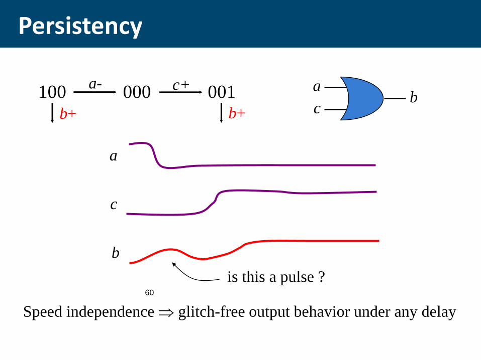
Persistency
100 000 001 a- c+
b+ b+
a
c b
a
c
b
is this a pulse ?
Speed independence glitch-free output behavior under any delay