astm d 2843 - fire testing brochures... · other smoke test apparatus, for example, astm e 1354...
TRANSCRIPT
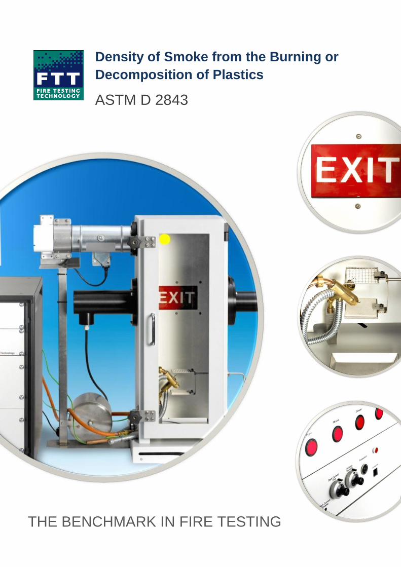
Density of Smoke from the Burning or
Decomposition of Plastics
ASTM D 2843
THE BENCHMARK IN FIRE TESTING
This reaction to fire test method covers a laboratory procedure for measuring
and observing the relative amounts of smoke obscuration produced by the
burning or decomposition of plastics. It is intended to be used for measuring the
smoke-producing characteristics of plastics under controlled conditions of
combustion or decomposition. The measurements are made in terms of the loss
of light transmission through a collected volume of smoke produced under
controlled, standardised conditions. This test is used by model code
organisations in controlling the use of plastic materials in light transmitting
applications. It can be used as an alternative to the ASTM E 84 smoke
measurement because this test method can readily be performed on
thermoplastic materials that may drip and fall out of the E 84 test apparatus.
Other smoke test apparatus, for example, ASTM E 1354 Cone Calorimeter, E
662 Smoke Density Chamber, etc. are also available from FTT.
ASTM D 2843 – Standard Test Method for Density of
Smoke from the Burning or Decomposition of Plastics
FTT ASTM D 2843 Exit Sign Test Apparatus
The FTT Exit Sign Test is designed for the measurement and observation of the smoke-producing
characteristics of plastics under controlled conditions of combustion or decomposition according to ASTM
D2843-10 but not to be used for measuring any other characteristics of the plastic combustion.
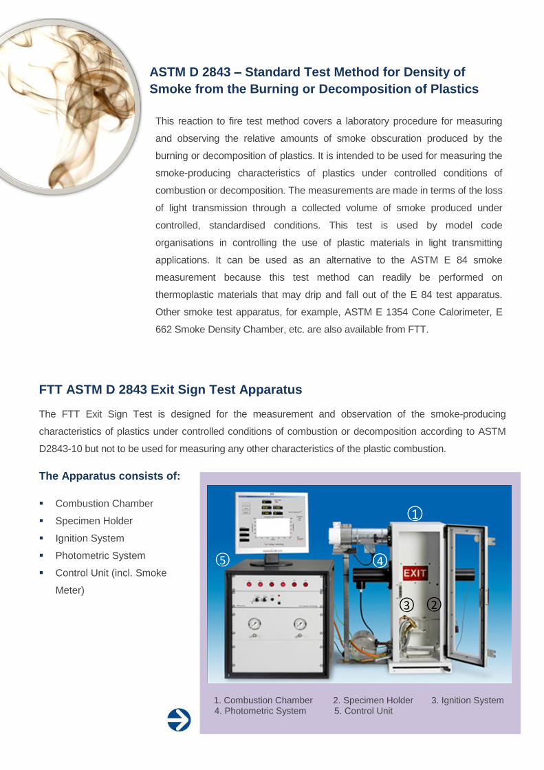
The Apparatus consists of:
Combustion Chamber
Specimen Holder
Ignition System
Photometric System
Control Unit (incl. Smoke
Meter)
1. Combustion Chamber 2. Specimen Holder 3. Ignition System 4. Photometric System 5. Control Unit
○1
○5 ○4
○3 ○2

The test specimen is exposed to flame for the duration of the test, and the
smoke is substantially trapped in the chamber in which combustion
occurs. A 25mm x 25mm x 6mm (1” x 1” x 1⁄4”) specimen is placed on a
supporting metal screen and burned in the test chamber under active
flame conditions using a propane burner operating at a pressure of 276
kPa (40 psi). The 300mm x 300mm x 790mm (12” x 12” x 31”) test
chamber is instrumented with a light source, photoelectric cell, and meter
to measure light absorption horizontally across the 300mm (12”) light
beam path. The chamber is closed during the 4 minute test period except
for the 25mm (1”) high ventilation openings around the bottom of the
chamber.
Measurement is by means of transmitting a beam of light through the smoke generated by the sample
under test to a light measuring receiver. Results obtained are in units of light absorption (%). The light-
absorption data are acquired by a user-friendly software tool and are plotted versus time. Two indexes, the
maximum smoke produced and the smoke-density rating, are used to rate the material. A heat resisting
glass door is fitted to allow observation of the test whilst it is in progress.
ExitSign Software
FTT Exit Sign Test Apparatus is a sophisticated instrument and in order to make the calibration and use
of the instrument extremely easy, the ExitSign software package is specially designed to complement
the instrument. ExitSign is a Microsoft Windows based application which assists with calibration routines,
acquires test data and produces test reports.
The Main panel is used to access all the functions available in ExitSign software:
Start Test Status Filter Check Print Report Configure About Exit

Schematic Diagram
Technical Specification
TEST CHAMBER
Overview Bench mounted draft free painted aluminium chamber with large lift-off door with window made from toughened glass giving a generous view of the specimen during a test. Mounted on a 360mm x 400mm x 57mm base.
Internal dimensions (m) 0.3 (L) x 0.3 (D) x 0.79 (H)
Voltage 96-264V 50/60Hz 1A
Exhaust In-Line axial industrial extraction fan with over temperature/current protection. Low noise plastic frame and plastic impeller. Outer diameter of exhaust fan: 104mm.
Exhaust flow rate (l/min) 1700
Interior light 2 x 6W fluorescent lights, 240V 50/60Hz, 3400 K
Top View (partial section)
1. Combustion Chamber: 300mm x 300mm x 790mm 2. Chamber Ventilation Slots (all 4 sides) 3. Heat Resistant Glazed Door 4. Base: 350mm x 400mm x 57mm 5. White on Red illuminated Exit Sign: 90mm x 150mm 6. Test Specimen: 25.4mm x 25.4mm x 6.2mm (not shown) 7. Specimen Holder: 64mm
2 of 6mm x 6mm, 0.9mm gauge
8. Calcium-silicate sheet or collector tray 9. Quench Pan (filled with water when in use) 10. Main Burner: Propane (operating at 276kPa (40psi)) 11. Aux Burner: Propane (operating at 138kPa (20psi)) 12. Sample Adjusting Handle 13. Light Source 14. Light Receiver 15. Heat Resistant Glazed Windows for light beam 2 x Ø70mm (int.) 16. Extraction Fan: 1700L/min 17. Main Burner Adjustment Handle 18. Anti-tilt Bracket 19. Filter Assembly 20. Butterfly Valve 21. Air Flow Device 22. Specimen Holder Clamp Screw (used only with the aux. burner)
Front View (partial section)
--- Air supply flexi-hose to burner (not drawn)

BURNER, GAS CONTROL SYSTEM
Burners A burner in compliance with ASTM D 2843 with a 0.13mm diameter orifice Auxiliary burner with a 1100g weight constructed from stainless steel to prevent movement of the burner during testing.
Burner positioning system Quick burner positioning system controlled via handle on the front of the chamber
Air supply device 160mm diameter stainless steel duct providing air to main burner
Gas type and pressure Commercial grade 85.0% minimum propane pressure regulated @ 40 psi for the main burner and @ 20 psi for the auxiliary burner Pressure displayed by two independent 63mm diameter bourdon tube gauges on front panel
PLC Integrated safety and control system, 24V DC powered.
Independent burner control
Thermocouple Type K interlock for main and auxiliary burners
Fan and exhaust damper control
Light source control 5V DC Switch Mode Power Supply
Input voltage 85-265V 47-63Hz
Cooling convection cooling
Operating ambient temperature -10 – 70°C
Over voltage protection
Over current protection
Flash back arrestor Safety precaution fitted on both burners
Photometric system Optical system positioned on the right houses a selenium cell. The light source houses a 1493 compact filament microscope lamp running between 5.3V DC and 6.3V DC which is situated on the left hand side of the chamber. The signal is monitored and processed via a Smoke Meter in the control unit.
SPECIMEN HOLDERS AND SUPPORT
Specimen Holder (x 4) 64mm x 64mm Stainless Steel Square of 6mm x 6mm, 0.9mm gauge wire
Quench pan (x 1) Stainless steel 150mm x 100mm x 20mm
Particles boards (x 4) ¼” Thick x 64mm x 64mm square calcium silicate
Stainless Steel Collector Tray (x 1)
2 ½” x 2 ½” x 3/8” deep with ½” square bottom
Due to the continuous development policy of FTT technical changes could be made without prior notice.
Charlwoods Road East Grinstead West Sussex RH19 2HL United Kingdom Tel: +44 (0) 1342 323600 Fax: +44 (0) 1342 323608 Email: [email protected] Web: www.fire-testing.com
Front View (Partial Section)
---- Air supply flexi-hose to burner (Not drawn) (Burner ‘Rest’ position)
770m
m
fire testing technology limited