asta linac beamline configurations & capabilities
TRANSCRIPT

P. Piot, ASTA users’ and PAC meeting
1
ASTA Linac Beamline configurations & capabilities
presented by P. Piot1,2 based on work by C. Prokop1, D. Mihalcea1,
F. Lemery1, M. Church2, and collaborations with B. E. Carlsten3, and P. Stoltz4
1 Northern Illinois University, 2 Fermilab, 3 Los Alamos National Laboratory, 4 Tech-X corp.
Credits: extensive use of beam-dynamics simulation codes provided by M. Borland (ANL), K. Flottmann,
M Dohlus (DESY), J. Qiang and R. Ryne (LBNL)
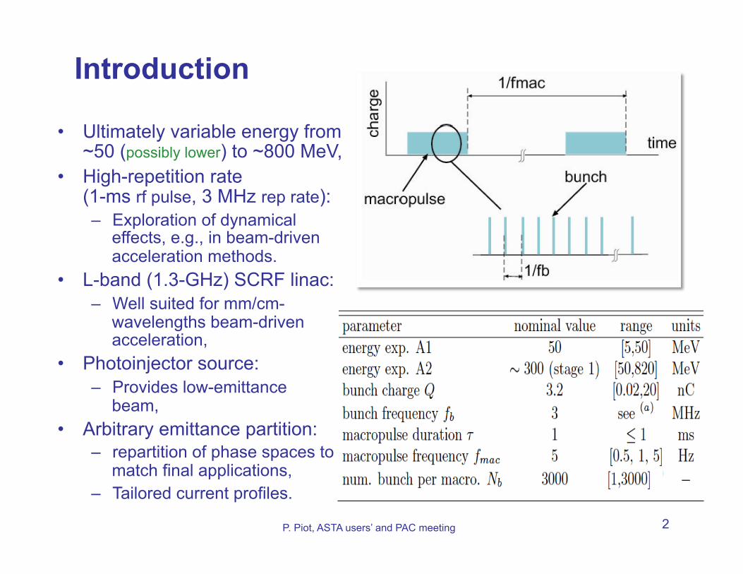
Introduction
P. Piot, ASTA users’ and PAC meeting 2
• Ultimately variable energy from ~50 (possibly lower) to ~800 MeV,
• High-repetition rate (1-ms rf pulse, 3 MHz rep rate): – Exploration of dynamical
effects, e.g., in beam-driven acceleration methods.
• L-band (1.3-GHz) SCRF linac: – Well suited for mm/cm-
wavelengths beam-driven acceleration,
• Photoinjector source: – Provides low-emittance
beam, • Arbitrary emittance partition:
– repartition of phase spaces to match final applications,
– Tailored current profiles.

ASTA linac Overview (injector area)
P. Piot, ASTA users’ and PAC meeting 3
vertical spectrometer
low-energy user area (A1)
photoinjector manipulations
diagnostics + matching in ACC1
• Cs2Te cathode driven by a Yb-fiber + Nd:YLF, • two SCRF booster cavities (CAV1, 2), • Round-to-flat beam transformer (RFTB), • Bunch compressor (BC1) + diagnostic section, • later stage: linearizer (CAV39), • low energy user area.
DESY-type L-band RF gun

Photoinjector capabilities (1)
P. Piot, ASTA users’ and PAC meeting 4
• nominal operating charge:
• energy • typical expected bunch
parameters scaling over the nominal charge range (for 1 laser uv pulse): – transverse emittance [µm]:
– longitudinal emittance [µm]
– uncompressed rms bunch length [mm]
CAV39 on
8
1
4
ε⊥ � 2.11Q0.69
ε|| � 30.05Q0.84
0.02 ≤ Q[nC] ≤ 3.2
E ≤ 50 MeV
[optimized with Astra (DESY) + GeneticOptimizer by Borland/Shang APS/ANL]
σ|| � 2.18Q0.13
P. Piot, IPA
C10

Flat-beam generation (on-going work)
• beams with asymmetric transverse-emittance partition can be produced
• optimized flat beams have similar 4D emittance than round beams
P. Piot, ASTA users’ and PAC meeting 5
εx
εy
ρeigenemittances evolution
in ASTA photoinjector
!
5
RTFB
P. Piot, IPA
C13

Low-energy bunch compression (1)
• Compression performed with a chicane-type bunch compressor (BC1)
• long. dispersion
P. Piot, ASTA users’ and PAC meeting 6
R56 = −19 cm
rms bunch length after BC1
• BC1 comp. nominally limited by 2nd order nonlinearities CAV39 eventually needed
single-particle-dynamics simulation of BC1
before BC1 after BC1
CAV39 ON CAV39 OFF
CAV39 ON
C. P
roko
p, N
IM A
(201
3)
[simulations w
ith Impact-T/Z (LB
NL) from
J. Qiang &
R. R
yne]
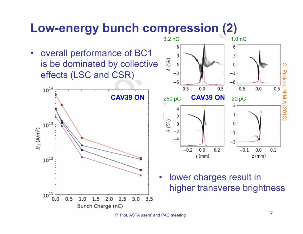
Low-energy bunch compression (2)
• overall performance of BC1 is be dominated by collective effects (LSC and CSR)
P. Piot, ASTA users’ and PAC meeting 7
• lower charges result in higher transverse brightness
20 pC 250 pC
3.2 nC 1.0 nC
CAV39 ON CAV39 ON
C. P
rokop, NIM
A (2013)

• Acceleration to ~250-300 MeV in one 8-cavity cryomodule • post cryomodule beamline:
– transport beam to high-energy user areas + high-power dumps – injection in IOTA
• high-energy user area include several parallel beamline • Further acceleration to ~800 MeV (“stage II”)
ASTA linac Overview (post ACC1 area)
P. Piot, ASTA users’ and PAC meeting 8
high-energy user area (A2)
IOTA transport + diagnostics
(A3)

post ACC1 beam optics
• Nominally designed to transport beam to HE dumps, • possibility to transport 50 MeV + have other low-energy
“insertable” experiment(s) located in transport line under consideration.
P. Piot, ASTA users’ and PAC meeting 9
HE dogleg (spectrometer)
end of photoinjector
BC1
C. P
rokop, FNA
L TM -2516-A
PC

Conventional bunch-temporal shaping • nominal bunch compression w.o.
CAV39 leads to long tail (good for sampling wakes – see Lemery’s talk)
• possibility to combine with disper- sive scarping (see Thangaraj’s talk)
• use of CAV39 to impart controlled nonlinearities (later stage)
P. Piot, ASTA users’ and PAC meeting 10
Q= 3.2 1.0 0.2 0.02 nC
afte
r BC
1 b
efor
e B
C1
C. P
rokop, IPAC
11
P. Piot, P
RL 2012
CAV39 OFF
CAV39 ON varied phase/amplitude

P. Piot, FLASH Accelerator workshop, Oct 4th, 2011 11
Generation of a witness population • Witness bunch produced
with a birefringent crystal • Drive/witness hierarchy
preserve downstream of BC1 • Preliminary experiments plan-
ned at A0/HBESL
to cathode
α-BBO
θ incoming uv laser pulse
L
δτ
drive
witness
GUN EXIT
drive
witness
AFTER BC1
CAV39 ON

EEX-based bunch temporal shaping
• emittance exchanger (EEX) could be used to shape the bunch current profile (bunch train, ramped bunches, …)
• 1st experiment planned w. Los Alamos to explore performance of pulse shaper
• need SC cavities to exploit multi-bunch capabilities
P. Piot, ASTA users’ and PAC meeting 12
P. Piot, A
AC
08, P. Piot, P
RS
TAB
2011, Y.-E S
un PR
L2010, C. P
rokop, IPAC
13]
(εx, εz) = (10, 1) µm (εx, εz) = (1, 10) µm
See
als
o pr
opos
al/ta
lk fr
om E
. Sim
akov

Ultra-low-emittance low-charge beams
• small laser spot on photocathode or field- emitter cathodes lead to extremely small emit- tances (sub-10-nm)
• produced beam are chal- lenging to diagnose with ASTA nominal diagnostics
• Field-emission with gated cathodes could enable the production of low-charge bunches repeated at 1.3 GHz with 1 ms!
P. Piot, ASTA users’ and PAC meeting 13
C. B
rau, SR
N (2012), W
. Gabella N
IMB
(2013), D. M
ihalcea, Phys. S
cript. (2013) S
ee re
cent
exp
erim
ent
P. M
usum
ecci
, PR
STA
B 2
012)
100% 95%
85%
90%
200 fC from field emitter
C. B
rau,
B. C
hoi V
ande
rbilt

Summary
• ASTA will provide beams within a vast parameter space, • Some of the advanced phase-space manipulations
pioneered at Fermilab’s A0 photoinjector are integral part of the design (flat beam) or will be installed early (EEX),
• Low-energy chicane-based bunch compression is not optimal but viable, at a later stage (after ACC1 installed), a second stage compressor will be added,
• Beam-dynamics performances of ASTA should be able to support most of the proposed experiments,
• We will be glad to collaborate and/or provide detailed calculations in support of your experiment [eventually all simulations files will be posted on ASTA web page so user can freely carry these calculations]
P. Piot, ASTA users’ and PAC meeting 14