assuring the right flow is our business. - petrostar valve · api 6d api 603 api 6f a bs 5351....
TRANSCRIPT

Assuring the right flow is our business.

ABOUT PETROSTAR 02-08
BALL VALVE 09-32
CAST STEEL GATE, GLOBE AND CHECK VALVE 33-51
SLAB GATE VALVE 52-54
BUTTERFLY VALVE 55-57
FORGED STEEL VALVE 58-62
MATERIALS 63
RAL COLOR CODE 64
TERMS AND CONDITIONS 65-66
ENGINEERING DATA 67-68
HOW TO ORDER 69-70
VALVE PHOTOS 71-72
CONTENT

A name synonymous with quality. With skills sharpened by many years we
offer a versatile range of durable valves, which ensures lowest ownership
cost and long period of trouble free operations.
We believe in long term relationship with our customers. That is why we
adhere to highest quality design, manufacturing, delivery and after sales
service. We achieve this by making every person in our organization
subscribe to quality procedures & methods and continuous training
programs that let our quality system evolve.
Our manufacturing range covers Ball, Gate, Globe, Check, Plug and
Butterfly valves with almost all kinds of metallurgy used in the Oil & Gas,
Petrochemical and Chemical industries. Petrostar offers valves in ASME
Class 150, 300, 600, 900, 1500 and 2500 ratings. Other standard ratings
and designs are available on request. This has taken us further to reach
our goal of leading the industry by becoming the most versatile and
reliable valve manufacturer.
ABOUT USPETROSTAR VALVE
www.petrostarvalve.com Page 02
ABOUT PETROSTAR VALVE
150300600900
Cast Steel Trunnion Mounted Ball Valve
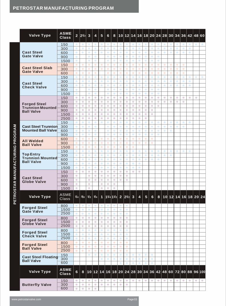
PETROSTAR MANUFACTURING PROGRAM
www.petrostarvalve.com Page 03
Valve TypeASMEClass 2 1/22 3 4 5 6 8 10 12 14 16 18 20 24 28 30 34 36 42 48 60
Cast Steel Gate Valve
Cast SteelGlobe Valve
Cast SteelCheck Valve
All Welded Ball Valve
Top Entry Trunnion Mounted Ball Valve
Valve TypeASMEClass
Forged SteelGate Valve
Forged SteelGlobe Valve
80015002500
Forged SteelCheck Valve
80015002500
80015002500
80015002500
Forged SteelBall Valve
150300600
Cast Steel Floating Ball Valve
Valve TypeASMEClass
Butterfly Valve150300600
1503006009001500
1503006009001500
150300600900150015030060090015002500
60090015001503006009001500
150300600
Cast Steel Slab Gate Valve
Forged SteelTrunnion MountedBall Valve
PE
TR
OS
TA
R M
AN
UF
AC
TU
RIN
G P
RO
GR
AM
1 5 6 8 10 12 14 16 18 20 241/2 3/4 1/41 1/21 1/222 3 43/81/4
6 8 10 12 14 16 18 20 24 28 30 34 36 42 48 60 80 88 96 10072

The Petrostar Quality Control
Program was implemented to
set the quality control standards
for pressure boundary castings,
and to ensure a consistent supply
of quality castings to Petrostar.
PETROSTAR QUALITY CONTROLPROGRAM (API 600/ISO 10434)
Before castings are released for
production, the Petrostar NDE
Inspector Level III, evaluates and
approves the submitted X-ray
films (100% coverage) as per API 600
SAMPLE CASTINGS
1. X-Ray Sample (pattern)
Approval Process;
2. X-Ray Monitoring Program;
3. Casting Monitoring Program.
Random X-ray monitoring
requires that castings taken every
six months from each vendor,
randomly by size and quantity
sets and X-rayed per B16.34
requirement.
X-RAY MONITORING:
Pro-Engineering model casting simulation program.
If casting fails to meet the X-ray
requirements of B16.34, Petrostar
Senior Metallurgist will issue a
corrective action request to the
vendor, including recommendations
for detailed methoding
change and re-X-ray.
Rejected castings due to defects
such as hydro-test leakage,
porosity, inclusions, shrinkage
indication discovered by X-ray or
machining, are entered into the
computer, as part of the statistical
control of each vendor.
CASTING MONITORING:
Petrostar applies Finite Element
Analysis for assistance at it's
design facilities.
Working together with foundry
engineers and our designers, we
continue improving the internal
integrity of castings, to X-Ray Level
II or better as a general standard.
FINITE ELEMENT ANALYSIS
Shorter delivery time,
Higher quality of commercial castings,
Optimum methoding system,
Elimination of trial at sample approval,
Improves the internal integrity of castings
(RT level 2 or better) at pattern approval,
Optimizes the metal flow and
solidification pattern,
Predicts internal defects,
Reduces scrap,
Optimizes the design of the castings,
Solves problems such as shrinkage and
porosity,without test castings,
Reduces NDE (X-ray) upgrading.
Benefits to Petrostar customers and to the foundries:
No shrinkage on a forged steel gate valve body simulation.
www.petrostarvalve.com Page 04
PETROSTAR QUALITY CONTROL SYSTEM
Fluid Mechanics Analysis of a top entry ball valve body.
Finite Element Analysis of a forged steel globe valve body.
Finite Element Analysis of a forged steel gate valve body.
Finite Element Analysis can be applied
to the design of valves with different
materials.

PETROSTAR VALVES IN WORK FIELD
Petrostar valves are widely applied to the field of petroleum, chemical, metallurgical, power, fuel gas, city pipeline networks and so on.
VALVES IN WORK FIELD
www.petrostarvalve.com Page 05

www.petrostarvalve.com Page 06
Gate valve stroke checking
with hydraulic actuator
Satisfied and careful agent network as the
backbone of petrostar business.
PETROSTAR LOCALIZED TESTING SYSTEM
Third Party inspections being carried out.
Globe valve under testing.

TESTING AND TREATMENT
Petrostar Valve manufactures valves with standard treated material, and is capable of supplying valves with special testing like radiographic examination, ultrasonic examination, dye penetrant testing, low temperature impact testing, xylon coating, PTFE coating, etc.
Besides common valves, we also offer special valves like cryogenic valves, bonnet extended valves, top entry and all-welded ball valve, wafer ball valve, metal seated ball valve, soft seated gate valve, bellow sealed globe valve, etc.
We offer wide ranges of metallurgy including duplex, super duplex, monel, inconel, copper, bronze, etc.
14" CLASS 300 CF8 gate valve, after cryogenic treatment.
Assembly of trunnion mounted ball valve Ware house
Dye penetrant test Fine lapping of ball
www.petrostarvalve.com Page 07

TESTING AND TREATMENT
Testing of 30" 300# top entry ball valve
www.petrostarvalve.com Page 08
Testing electric actuator
Lathe in serviceClass 600 6" ball valve, with primer.

FLOATING BALL VALVETRUNNION MOUNTED BALL VALVETOP ENTRY BALL VALVEALL WELDED BALL VALVEWAFER TYPE BALL VALVE
API 6DAPI 603API 6FABS 5351

Bi-directional sealing system:
Principle of sealing:
The sealing system of trunnion mounted
ball valves manufacture d by Petrostar
are spring assisted ones, which provide
tightness at low or high pressures range .
The spring assistance provides the
necessary initial sealing pressure at low
pressure values, while the rising differential
pressure resu lting from the pressure increase
presses the seat ring onto the ball surface .
The ball valves can be assembled into the line
regardless of the flow direction.
Automatic reduction of body cavity pressure:
The sealing system design in ball va lves
automatically allows the release of the
excessive body cavity pressure into the
lower pipe pressure side in case of
pressure differences greater than
10 bars.
The special sealing system of ball valves
assures the inlet and outlet side tightness
of body cavity. In case of failure of either
gasket, the remaining seal provides the
tightness of the body cavity. The double
sealing system of trunnion mounted ball
valves includes a PFTE insert besides the
specially formed elastomer sealing
element, which also fulfills the bearing
function between the ball and the seat
ring. Furthermore, it protects the gasket
from failures caused by solid particles and
by the erosion of the flowing medium.
www.petrostarvalve.com Page 10
TRUNNION MOUNTED BALL VALVE

Petrostar trunnion-mounted ball valves offer increased value by incorporating advanced design features.
TRUNNION MOUNTED BALL VALVE STRUCTURE
TRUNNION-MOUNTED BALLThe ball is fixed and the seat rings are floating,
free to move along the valve axis.
Side load generated by the pressure acting
on the ball is absorbed by bearings.
At low pressure the seat sealing action is
achieved by the thrust of the springs acting
on the seat rings.
As the pressure increases the fluid
pressure pushes the seat rings
against the ball.
Two independent floating seat rings assure
the bi-directional tightness of the valve.
The seats are carefully designed to minimize
the torque required to operate the valves
without losing sealing power, which is assured
from zero differential pressure to the valve's
maximum rated pressure.
FLOATING SEAT RINGS
www.petrostarvalve.com Page 11

Self-relieving seats are supplied as a
standard feature. Double piston or combination
seats (self-relieving/upstream, double piston/
downstream) can be supplied on request.
The ball and stem are independent to minimize the
effect of the side thrust generated by the pressure
acting on the ball.
INDEPENDENT BALL AND STEM
The electrical conductance continuity
between all the metallic components is
guaranteed and certified.
ANTI-STATIC DESIGN
Accurate machining of
stem and bonnet sealing
surfaces ensures
compliance with the
most severe pollution
control regulations.
LOW EMISSIONVALVES
The double block and
bleed feature, both
with the ball in the fully
closed or fully open
position, is a standard
feature.
DOUBLEBLOCK & BLEED
TRUNNION MOUNTED BALL VALVE STRUCTURE
www.petrostarvalve.com Page 12

Design Features
FEATURES SIDE-ENTRY WELDED BODY TOP-ENTRY
Trunnion Mounted
Independent Stem & Ball
Independent Floating Seats
Primary Soft Seat - Secondary Metal Seat
Primary Metal Seat - Secondary Soft
Metal to Metal Seat
Self Relieving Seats
Single Piston Seat Effect
Double Piston Seat Effect
Combination (Self Relieving/Double Piston) Seats
API 6A or API 6D Design and Construction
Face to Face Dimensions to API 6D and ANSI B16.10
Fire Safe Design to API 6FA - API 607 - BS 6755 Part 2
Full, Reduced or Venturi Port
Flanged Ends - Welded Ends - Hub Ends
Transition Pups for Welded Ends Valves
Antistatic
Anti-Blowout Stem
Double Block and Bleed
Double Body Seals
Triple Stem
Drain Plug
Drain Valve
Vent Valve (on 6" and larger)
Emergency Sealant Injection on Stem
Emergency Sealant Injection on Seats (on 6" & larger)
Seat Pocket Overlay
Seals Area Overlay
Wetted Parts Overlay
Body Internal Lining
Extended Stem for Underground Installation
Extended Bonnet for Low or High Temperature
Locking Device
Lifting Lugs
Supporting Feet
Manual or Motorized Operation
In-line Maintenance
On site Maintenance
Standard
Standard
Standard
Standard
On Request
On Request
Standard
Standard
On Request
On Request
As Required
Standard
Standard
As Required
As Required
On Request
Standard
Standard
As Required
Standard
Standard
Standard
Standard
On Request
Standard
Standard
On Request
On Request
On Request
On Request
On Request
As Required
As Required
On Request
As Required
N/A
Yes
Possibility to Check Seat Integrity In Line with Ball in Open or Closed Position
Standard on 6" and Larger
Standard on 6" and Larger
Standard
Standard
Standard
Standard
On Request
N/A
Standard
Standard
On Request
On Request
As Required
Standard
Standard
As Required
As Required
On Request
Standard
Standard
As Required
Standard
Not Required
Standard
Standard
On Request
Standard
Standard
On Request
On Request
On Request
On Request
N/A
As Required
N/A
On Request
As Required
N/A
N/A
Standard
Standard
Standard
Standard
On Request
On Request
Standard
Standard
On Request
On Request
As Required
Standard
Standard
As Required
As Required
On Request
Standard
Standard
As Required
Standard
Standard
Standard
Standard
On Request
Standard
Standard
On Request
On Request
On Request
On Request
On Request
As Required
As Required
On Request
As Required
Yes
Yes
Note: Other features are available on request.
BALL VALVE DESIGN FEATURES
www.petrostarvalve.com Page 13

An emergency sealant injection port is located between the upper O-rings and the graphite gasket.
An emergency sealant injection is available in the seating area.
With a compensating seat design, the contact area between ball and seat ring is automatically enlarged under higher pressure from medium, in order to ensure sealing performance. When there's lower pressure from medium, the contact area is smaller, which achieves lower stem torque.
Metal-to-metal seat design is used for abrasive service or high temperature that a resilient material is prohibited.
www.petrostarvalve.com Page 14
BALL VALVE DESIGN FEATURES

BALL VALVE DESIGN FEATURES
Two O-rings and one graphitegasket ensure the stem seal.The graphite gasket can bereplaced while the valve is underpressure and with the ball in anyposition, by removing the adaptorplate, after having released anypressure that may exist betweenthe upper O-ring and the graphitegasket, through the greaseinjection fitting hole.The O-rings can be replaced withthe valve in fully open or fullyclosed position by removing thestem cover after having releasedall the pressure in the bodycavity.
STEM SEALING
Mechanical stops ensurecontrol over ball rotation.
BALL SEAT ALIGNMENT
Stem is retained by the stemcover. Other designs availableon request
ANTI-BLOWOUT STEM
The double sealing action ofO-rings and graphite gaskets inall the static joints of the bodycomponents, ensures zeroleakage and the Fire Safe feature.
BODY SEALINGLip-seal rings and/or graphitegaskets can be used for specialservice.
Each valve is supplied c/wemergency sealant injectionfeature located between theupper O-rings and the graphitegasket. Emergency sealantinjection feature on seats isavailable on request only,for 6" full port and larger.Emergency grease injectionfeatures are not available on lowand high temperature valves.
EMERGENCY SEALANTINJECTION
Valve designs are availablewith extended bonnets forapplications in extremetemperature service.Extended bonnets arerecommended for serviceat temperatures below-50 or above 220 .
EXTENDED BONNET
www.petrostarvalve.com Page 15

STANDARDSINGLE PISTON EFFECT (SELF-RELIEVING SEATS)
Fluid pressure, both upstreamand downstream, creates aresultant thrust that pushesthe seat rings against the ball.Fluid pressure acting in thebody cavity creates a resultantthrust that pushes the seatrings away from the ball.The single piston designpermits the automatic releaseof any over pressure in the bodycavity when the valve is in thefully open or fully closedposition, therefore the seatrings are "self-relieving".
SINGLE PISTON EFFECT
Fluid pressure, bothupstream and downstream,as well as in thebody cavity creates aresultant thrust thatpushes the seat ringstowards the ball.Valves with double pistoneffect seat rings require arelief valve in order toreduce the build-up ofover pressure in thebody cavity.
OPTIONALDOUBLE PISTON EFFECT
BALL VALVE DESIGN FEATURES
www.petrostarvalve.com Page 16

Temp & pressure: ASME B 16.34, BS 5351
Wall thickness: ASME B 16.34, BS 5351
Bore dimension: API 6D, BS 5351
Face to face: ASME B 16.10, BS 2080
Flange dimension: ASME B 16.5, BS 1560
Test & inspection: API 598, API 6D, BS 5146
Body material: WCB, LCB, LCC, CF8, CF8, CF3, CF3M
Full port design
Bolted bonnet, split body
Floating ball type
Blow-out proof stem
Fire durable construction
Anti static device
Stopper device
ISO 5211 mounting pad
Flanged or butt welding ends
Available with worn gear operator
1CAST STEEL FLOATING BALL VALVE( 1 /2")
Design description: >> >>
www.petrostarvalve.com Page 17
Standards

1
2
3
4
5
6
7
8
9
10
11
12
13
Body
Bonnet
ball
Stem
Seat ring
Bonnet gasket
Bonnet stud
Bonnet stud nut
Packing
Gland flange
Gland bolt
Stop plate
Handle
A216-WCB
A216-WCB
A182-F3041)
A276-F304
A351-CF8M
A351-CF8M
A182-F316
A276-316
R. PTEE
A352-LCB
A352-LCB
A182-F3041)
A276-304
NO Part nameASTM Material
Carbon steel 18Cr-9Ni-2Mo Carbon steel
Note:1). A 105+ENP optional; 2). Spiral wound construction
PTEE
A193-B8
A194-8
Graphite+3042)
A193-B7
A194-2H
Graphite+3042)
A320-L7
A194-4
A216-WCB
A193-B7
Caron steel
A351-CF8M
A193-B8
Caron steel+Zn
A352-LCB
A193-B7
Caron steel
Caron steel
Materials of parts
PTEE
>>
www.petrostarvalve.com Page 18
1CAST STEEL FLOATING BALL VALVE( 1 /2")

Pressure temperature rating , ASME B16.34 BS5351
Shell thickness, ASME B16.34 BS5351
Pore hole dimension, API 6D BS5351
Face to face, ASME B16.10 API 6D
Connection dimension, ASME B16.5 BS1560
Test and inspection conform to , API 6D BS5146
Main materials,A105 LF2 F304 F304L F316L
ALL WELDED BALL VALVE
Main part materials list
NO
126789101112131422242526304546495051525354555759
Part name Carbon steel Low Temp. steel Stainless steel
BodyBonnetInject valveO-ringO-ringSeat retainerRingSpringBallSliding bearingStatic springStemGasketO-ringO-ringPackingScrewWaste valveBackingBack pinUpper bushingGasketPositioning pinO-ringPacking seatCoupling plateBase frame
ASTM A105ASTM A105ANSI 1045VITONVITONASTM A105RPTEEInconelx-750ASTM A 105+ENP304+PTEEA276-316A182-F6a304+PTEEVITONVITONGraphiteASTM A 193-B7/B7MANSI 1045ASTM A105ANSI 1045ASTM A105304+GraphiteANSI 1045VITONASTM A182-F6aASTMA105ANSI 1025
ASTM A305 LF2ASTM A305 LF2ANSI 1045VITONVITONASTM A305 LF2+ENPPTEEInconelx-750ASTM A305 LF2+ENP304+PTEEA276-316A182-F6a304+PTEEVITONVITONGraphiteASTM A 193-B7MANSI 1045ASTM A305 LF2+ENPASTM A305 LF2+ENPASTM A305 LF2+ENP304+GraphiteANSI 1045VITONASTM A182-F6aASTM A350 LF2ANSI 1025
ASTM A316ASTM A316A276-316VITONVITONASTM A182 F316PTEEInconelx-750ASTM A182 F316316+PTEEA276-316ASTM A182-F6a316+PTEEVITONVITONGraphiteASTM A 193-B8ASTM A182 F316ASTM A182 F316ASTM A182 F316ASTM A182 F316316+GraphiteA276-316VITONASTM A182 F316ASTM A182 F316A276-316
Applicable standards:
www.petrostarvalve.com Page 19

1 Body
2 Closure
3 Ball
4 Seat
5 Stem
6 Bearing retainer
7 Stem cover
8a Operator flange
9a Stem key
10b Stem gasket
10c Stem cover gasket
11b Stem O-ring
11c Stem cover O-ring
11d Seat O-ringg
15a Stem cover/body
socket screw(2)
15b Operator flange/body socket screw
15d Stop seat socket screw(1)(2)
16a Seat spring
16b Antistatic spring
17a Stem greaser
17e Vent bleeder valve
17g Drain plug
20b Ball bushing
21a Stem thrust washer
21b Ball thrust washer
22a Bearing retainer pin
22b Operator flange/body pin
23a Lifting lug(2)
23b Valve support (2)
24a Stop seat washer(1)(2)
(1) Only for DN > 8" (2) Not visible in below drawing.
REDUCED BORE BALL VALVE
www.petrostarvalve.com Page 20
Materials of parts

NO Part name
123456789101112131415161718192021
ASTM MaterialCarbon steel 18Cr-9Ni-2Mo Carbon steel
Materials of parts
BodyBonnetballStemSeatStem insertSeat springSeat O-ringStem O-ringBonnet gasketBonnet O-ringSntistatic springGrounding plungerBonnet studBonnet stud nutTrunnionTrunnion bearingGland flangeGland boltStop plateHandle
A216-WCBA216-WCBA182-F3041)A276-304A105+ENP
A351-CF8MA351-CF8MA182-F316A276-316A182-F316
A352-LCBA352-LCBA182-F3041)A276-304A350-LF2+ENP
Claa filled PTEEA313-304NBRNBRGraphite+3042)NBRA313-304A216-WCBA193-B7A194-2HA276-304304+PTEEA216-WCBA193-B7Carbon steel
Inconel X-750VitonVitonGraphite+3162)VitonA313-316A182-F316A193-B8A194-8A276-316316+PTEEA351-CF8MA193-B8Carbon steel+ZnCarbon steel
A313-304VitonVitonGraphite+3042)VitonA313-304A182-F304A320-L7A194-4 A276-304304+PTEEA352-LCBA193-B7Carbon steell
Note:1).A 105+ENP optional; 2). Spiral wound construction
Full port design
BB, Bolted bonnet, split body
Three piece body for 12"& above
Trunnion mounted ball type
Blow-out proof stem
Fire durable construction
Anti static device
Stopper device
ISO 5211 Mounting pad
Flanged or butt welding ends
Available with worm gear operator
Design description:
Applicable standards:Steel ball valves, API 608/API 6D
Steel ball valves, ISO 14313
Fire durable,Ap1607
Anti static, API 608
Steel valves, ASME B16.34
Face to face, ASME B16.10
End flanges, ASME B16.5
Butt welding ends, ASME B16.25
Inspection and test, API 598/API 6D
TRUNNION MOUNTED BALL VALVE
www.petrostarvalve.com Page 21

TOP ENTRY TRUNNION MOUNTED BALL VALVE
Size:2"~24"
Class:150~1500
Top entry body
Trunnion mounted ball , full & reduced bore
Anti-static device
Blow-out proof stem
Fire safe design
Emergency sealant injector(6"& larger)
Design: ASME B 16.34/API 6D
Face to face: ASME B 16.10/API 6D
End to end: ASME B 16.10/API 6D
Flange end: ASME B 16.5
BW end: ASME B 16.25
Test: API 6D API 598
Fire safe test: API 607/API 6FA
Special : NACE MR-01-75
Standards
www.petrostarvalve.com Page 22
Design description:

DIMENSIONS & WEIGHTS
www.petrostarvalve.com Page 23
W
w
A
H
d
A
L
H
L
2PC, CLASS 150 TRUNNION FULL BORE VALVE (FIG NO. F1--)
Valve Size
Bore Size (d)
RF Face to Face
BW End to End
Flange OD
Weight(Lbs)
Center to Lever H
Handle Length W
Center to Gear H
Handwheel Dia W
2"
1.93"
7.00"
8.50"
6.00"
30.00
8.30"
13.78"
-
-
3"
2.91"
8.00"
11.13"
7.50"
78.00
10.16"
15.75"
-
-
4"
3.94"
9.00"
12.00"
9.00"
118.00
11.80"
17.69"
-
-
6"
5.91"
15.50"
18.00"
11.00"
270.00
13.50"
41.34"
14.00
20.00
8"
7.91"
18.00"
20.50"
13.50"
4800.00
-
-
14.80"
23.62"
10"
9.92"
21.00"
22.00"
16.00"
570.00
-
-
21.50"
27.56"
12"
11.93"
24.00"
25.00"
19.00"
1010.0
-
-
23.80"
39.38"
14"
13.15"
27.00"
30.00"
21.00"
1195.0
-
-
25.40"
39.38"
16"
15.16"
30.00"
33.00"
23.50"
1800.0
-
-
28.45"
39.38"
18"
17.17"
34.00"
36.00"
25.00"
1950.0
-
-
29.00"
39.38"
20"
19.17"
36.00"
39.00"
27.50"
3600.0
-
-
32.00"
39.38"
24"
23.19"
42.00"
45.00"
32.00"
4800.0
-
-
35.70"
39.38"
2PC, CLASS 150 TRUNNION REDUCED BORE VALVE - (FIG. NO. G1--)
Valve Size
Bore Size (d)
Weight(Lbs)
Center to Lever H
Handle Length W
Center to Gear H
Handwheel Dia W
2"
1.50"
24.00
7.80"
13.78"
-
-
3"
1.93"
48.00
8.30"
13.78"
-
-
4"
2.91"
79.00
10.16"
15.75"
-
-
6"
3.94"
120.00
11.80"
16.69"
-
-
8"
5.91"
320.00
13.50"
41.34"
14.00
20.00"
10"
7.91"
500.00
-
-
14.80"
23.62"
12"
9.92"
605.0
-
-
21.50"
27.56"
14"
11.93"
1150.0
-
-
23.80"
31.50"
16"
13.15"
1250.0
-
-
25.40"
39.38"
18"
15.16"
1900.0
-
-
28.45"
39.38"
20"
17.17"
2300.0
-
-
29.00"
39.38"
24"
19.17"
4450.0
-
-
32.00"
39.38"
Valve Size
Bore Size (d)
RF Face to Face
BW End to End
Flange OD
Weight(Lbs)
Center to Lever H
Handle Length W
Center to Gear H
Handwheel Dia W
2PC, CLASS 300 TRUNNION FULL BORE VALVE (FIG NO. F3--)
2"
1.93"
8.50"
8.50"
6.50"
38.00
8.50"
17.00"
-
-
3"
2.91"
11.13"
11.13"
8.25"
85.00
10.25"
22.20"
-
-
4"
3.94"
12.00"
12.00"
10.00"
130.00
12.00"
24.00"
-
-
6"
5.91"
15.88"
18.00"
12.50"
315.00
13.75"
42.00"
14.50
20.00
8"
7.91"
19.75"
20.50"
15.00"
510.00
-
15.80"
23.62"
10"
9.92"
22.38"
22.00"
17.50"
630.00
-
22.50"
27.56"
12"
11.93"
25.50"
25.00"
20.50"
1110.0
-
24.80"
39.38"
14"
13.15"
30.00"
30.00"
23"
1295.0
-
25.40"
39.38"
16"
15.16"
33.00"
33.00"
25.50"
2259.0
-
28.55"
39.38"
18"
17.17"
36.00"
36.00"
28.00"
2600.0
-
29.52"
39.38"
20"
19.17"
39.00"
39.00"
30.50"
4365.0
-
32.50"
39.38"
24"
23.19"
45.00"
45.00"
36.00"
5800.0
-
36.90"
39.38"

DIMENSIONS & WEIGHTS
www.petrostarvalve.com Page 24
A
H
L W
w
2PC, CLASS 300 TRUNNION REDUCED BORE VALVE - (FIG. NO. G3--)
Valve Size
Bore Size (d)
Weight(Lbs)
Center to Lever H
Handle Length W
Center to Gear H
Handwheel Dia W
2"
1.50"
32.00
8.00"
15.00"
-
-
3"
1.93"
66.00
8.50"
17.00"
-
-
4"
2.91"
88.00
10.25"
22.20"
-
-
6"
3.94"
140.00
12.00"
24.00"
-
-
8"
5.91"
350.00
13.75"
42.00"
14.50
20.00
10"
7.91"
530.00
-
-
15.80"
23.62"
12"
9.92"
695.0
-
-
22.50"
27.56"
14"
11.93"
1250.0
-
-
24.80"
39.38"
16"
13.15"
1460.0
-
-
25.40"
39.38"
18"
15.16"
2350.0
-
-
28.55"
39.38"
20"
17.17"
2800.0
-
-
29.52"
39.38"
24"
19.17"
5150.0
-
-
32.50"
39.38"
2PC, CLASS 600 TRUNNION FULL BORE VALVE (FIG NO. F6--)
Valve Size
Bore Size (d)
RF Face to Face
RJ End to End
BW End to End
Flange OD
Weight(Lbs)
Center to Lever H
Handle Length W
Center to Gear H
Handwheel Dia-W
2"
1.93"
11.50"
11.63"
11.50"
6.50"
62.00
8.70"
15.00"
-
-
3"
2.91"
14.00"
14.13"
14.00"
8.25"
125.00
10.70"
17.00"
-
-
4"
3.94"
17.00"
17.13"
17.00"
10.75"
190.00
12.40"
20.00"
-
-
6"
5.91"
22.00"
22.13"
22.00"
14.00"
495.00
-
-
15.00"
23.62"
8"
7.91"
26.00"
26.13"
26.00"
16.50"
860.0
-
-
16.80"
27.56"
10"
9.92"
31.00"
31.13"
31.00"
20.00"
1295.0
-
-
23.80"
39.38"
12"
11.93"
33.00"
33.13"
33.00"
22.00"
1950.0
-
-
25.80"
39.38"
14"
13.15"
35.00"
35.13"
35.00"
23.75"
2203.0
-
-
26.90"
39.38"
16"
15.16"
39.00"
39.13"
39.00"
27.00"
3100.0
-
-
30.00"
39.38"
18"
17.17"
43.00"
43.13"
43.00"
29.25"
3950.0
-
-
33.00"
39.38"
20"
19.17"
47.00"
47.25"
47.00"
32.00"
5100.0
-
-
36.00"
39.38"
24"
23.19"
55.00"
55.38"
55.00"
37.00"
8400.0
-
-
39.00"
39.38"
2PC, CLASS 600 TRUNNION REDUCED BORE VALVE - (FIG. NO. G6--)
Valve Size
Bore Size (d)
Weight(Lbs)
Center to Lever H
Handle Length W
Center to Gear H
Handwheel Dia W
2"
1.50"
52.00
8.20"
15.00"
-
-
3"
1.93"
97.00
8.70"
15.00"
-
-
4"
2.91"
155.00
10.70"
17.00"
-
-
6"
3.94"
340.00
12.40"
20.00"
-
-
8"
5.91"
700.00
-
-
15.00"
23.62"
10"
7.91"
1050.0
-
-
16.80"
27.56"
12"
9.92"
1600.0
-
-
23.80"
39.38"
14"
11.93"
1950.0
-
-
25.80"
39.38"
16"
13.15"
2800.0
-
-
26.90"
39.38"
18"
15.16"
3300.0
-
-
30.00"
39.38"
20"
17.17"
4700.0
-
-
33.00"
39.38"
24"
19.17"
7500.0
-
-
36.00"
39.38"
H
d
A
L

H
P
LW
w
DIMENSIONS & WEIGHTS
www.petrostarvalve.com Page 25
Valve Size
Bore Size (d)
Weight(Lbs)
Center to Lever H
Handle Length W
Center to Gear H
Handwheel Dia W
Valve Size
Bore Size (d)
RF Face to Face
BW End to End
Flange OD
Weight(Lbs)
Center to Lever H
Handle Length W
Center to Gear H
Handwheel Dia W
Valve Size
Bore Size (d)
RF Face to Face
BW End to End
Flange OD
Weight(Lbs)
Center to Lever H
Handle Length W
Center to Gear H
Handwheel Dia W
3PC/WELD, CLASS 150 TRUNNION FULL BORE VALVE (FIG NO. H1-- / M1--)
2"
1.93"
7.00"
8.50"
6.00"
62.00
6.30"
13.78"
-
-
3"
2.91"
8.00"
11.13"
7.50"
115.00
8.16"
15.75"
-
-
4"
3.94"
9.00"
12.00"
9.00"
200.00
9.80"
17.69"
-
-
6"
5.91"
15.50"
18.00"
11.00"
386.00
12.50"
41.34"
12.00
20.00
8"
7.91"
18.00"
20.50"
13.50"
585.00
-
-
12.80"
23.62"
10"
9.92"
21.00"
22.00"
16.00"
873.00
-
-
18.50"
27.56"
12"
11.93"
24.00"
25.00"
19.00"
1210.0
-
-
20.80"
39.38"
14"
13.15"
27.00"
30.00"
21.00"
1675.0
-
-
22.40"
39.38"
16"
15.16"
30.00"
33.00"
23.50"
2359.0
-
-
24.45"
39.38"
18"
17.17"
34.00"
36.00"
25.00"'
3400.0
-
-
25.00"
39.38"
20"
19.17"
36.00"
39.00"
27.50"
4465.0
-
-
28.00"
39.38"
24"
23.19"
42.00"
45.00"
32.00"
6900.0
-
-
30.70"
39.38"
30"
28.94"
51.00"
55.00"
38.75"
18000
-
-
38.03"
39.38"
36"
34.41"
60.00"
68.00"
46.00"
27000
-
-
43.15"
39.38"
3PC/WELD, CLASS 150 TRUNNION REDUCED BORE, VALVE (FIG. NO. J1--/ N1--)
2"
1.50"
58.00
6.30"
13.78"
-
-
3"
1.93"
65.00
6.30"
13.78"
-
-
4"
2.91"
138.00
8.16"
15.75"
-
-
6"
3.94"
210.00
9.80"
16.69"
-
-
8"
5.91"
425.00
12.50"
41.34"
12.00
20.00"
10"
7.91"
660.00
-
-
12.80"
23.62"
12"
9.92"
1050.0
-
-
18.50"
27.56"
14"
11.93"
1450.0
-
-
20.80"
31.50"
16"
13.15"
1600.0
-
-
22.40"
39.38"
18"
15.16"
2650.0
-
-
24.45"
39.38"
20"
17.17"
3475.0
-
-
25.00"
39.38"
24"
19.17"
4900.0
-
-
28.00"
39.38"
30"
23.19"
7950.0
-
-
30.70"
39.38"
36"
28.94"
22500
-
-
38.03"
39.38"
3PC/WELD, CLASS 300 TRUNNION, FULL BORE, VALVE (FIG NO. H3--/ M3--)
2"
1.93"
8.50"
8.50"
6.50"
64.00
6.50"
17.00"
-
-
3"
2.91"
11.13"
11.13"
8.25"
120.00
8.25"
22.20"
-
-
4"
3.94"
12.00"
12.00"
10.00"
218.00
10.00"
24.00"
-
-
6"
5.91"
15.88"
18.00"
12.50"
450.00
12.75"
42.00"
12.50
20.00
8"
7.91"
19.75"
20.50"
15.00"
680.00
-
-
16.80"
23.62"
10"
9.92"
22.38"
22.00"
17.50"
1175.0
-
-
18.50"
27.56"
12"
11.93"
25.50"
25.00"
20.50"
1725.0
-
-
20.80"
39.38"
14"
13.15"
30.00"
30.00"
23"
2400.0
-
-
21.40"
39.38"
16"
15.16"
33.00"
33.00"
25.50"
3255.0
-
-
23.55"
39.38"
18"
17.17"
36.00"
36.00"
28.00"
3750.0
-
-
25.52"
39.38"
20"
19.17"
39.00"
39.00"
30.50"
5100.0
-
-
27.50"
39.38"
24"
23.19"
45.00"
45.00"
36.00"
8100.0
-
-
31.90"
39.38"
30"
28.94"
55.00"
55.00"
43.00"
21000
-
-
39.00"
39.38"
36"
34.41"
68.00"
68.00"
50.00"
28750
-
-
45.15"
39.38"
Valve Size
Bore Size (d)
Weight(Lbs)
Center to Lever H
Handle Length W
Center to Gear H
Handwheel Dia W
3PC/WELD, CLASS 300 TRUNNION, REDUCED BORE, VALVE - (FIG. NO. J3--/ N3--)
2"
1.50"
60.00
6.10"
15.00"
-
-
3"
1.93"
75.00
6.50"
17.00"
-
-
4"
2.91"
145.00
8.25"
22.20"
-
-
6"
3.94"
270.00
10.00"
24.00"
-
-
8"
5.91"
550.00
12.75"
42.00"
12.50
20.00
10"
7.91"
700.00
-
-
16.80"
23.62"
12"
9.92"
1350.0
-
-
18.50"
27.56"
14"
11.93"
1950.0
-
-
20.80"
39.38"
16"
13.15"
2250.0
-
-
21.40"
39.38"
18"
15.16"
3250.0
-
-
23.55"
39.38"
20"
17.17"
4000.0
-
-
25.52"
39.38"
24"
19.17"
5750.0
-
-
27.50"
39.38"
30"
23.19"
9400.0
-
-
31.90"
39.38"
36"
28.94"
25000
-
-
39.00"
39.38"

DIMENSIONS & WEIGHTS
www.petrostarvalve.com Page 26
HP
LW
w
3PC/WELD, CLASS 600 TRUNNION REDUCED BORE VALVE - (FIG. NO. J6--/ N6--)
3PC/WELD, CLASS 900 TRUNNION FULL BORE VALVE (FIG NO. H9--/ M9--)
3PC/WELD, CLASS 600 TRUNNION FULL BORE VALVE (FIG NO. H6--/ M6--)
2"
1.93"
11.50"
11.63"
11.50"
6.50"
75.00
6.70"
15.00"
-
-
3"
2.91"
14.00"
14.13"
14.00"
8.25"
145.00
9.70"
17.00"
-
-
4"
3.94"
17.00"
17.13"
17.00"
10.75"
270.00
10.40"
20.00"
-
-
6"
5.91"
22.00"
22.13"
22.00"
14.00"
600.00
-
-
15.00"
23.62"
8"
7.91"
26.00"
26.13"
26.00"
16.50"
1125.0
-
-
16.80"
27.56"
10"
9.92"
31.00"
31.13"
31.00"
20.00"
1750.0
-
-
18.80"
39.38"
12"
11.93"
33.00"
33.13"
33.00"
22.00"
2450.0
-
-
20.80"
39.38"
14"
13.15"
35.00"
35.13"
35.00"
23.75"
2500.0
-
-
21.90"
39.38"
16"
15.16"
39.00"
39.13"
39.00"
27.00"
3500.0
-
-
23.00"
39.38"
18"
17.17"
43.00"
43.13"
43.00"
29.25"
4550.0
-
-
26.00"
39.38"
20"
19.17"
47.00"
47.25"
47.00"
32.00"
6100.0
-
-
28.00"
39.38"
24"
23.19"
55.00"
55.38"
55.00"
37.00"
11000
-
-
32.00"
39.38"
30"
28.94"
65.00"
65.50"
65.00"
44.50"
23000
-
-
36.00"
39.38"
36"
34.41"
82.00"
82.63"
82.00"
51.75"
32000
-
-
45.00"
45.00"
Valve Size
Bore Size (d)
RF Face to Face
RJ End to End
BW End to End
Flange OD
Weight(Lbs)
Center to Lever H
Handle Length W
Center to Gear H
Handwheel Dia-W
Valve Size
Bore Size (d)
Weight(Lbs)
Center to Lever H
Handle Length W
Center to Gear H
Handwheel Dia W
2"
1.50"
72.00
6.20"
15.00"
-
-
3"
1.93"
97.00
6.30"
15.00"
-
-
4"
2.91"
195.00
6.70"
17.00"
-
-
6"
3.94"
380.00
8.40"
20.00"
-
-
8"
5.91"
700.00
-
-
15.00"
23.62"
10"
7.91"
1250.0
-
-
16.80"
27.56"
12"
9.92"
1900.0
-
-
18.80"
39.38"
14"
11.93"
2600.0
-
-
20.80"
39.38"
16"
13.15"
3100.0
-
-
21.90"
39.38"
18"
15.16"
3900.0
-
-
23.00"
39.38"
20"
17.17"
5100.0
-
-
26.00"
39.38"
24"
19.17"
7500.0
-
-
28.00"
39.38"
30"
23.19"
16000
-
-
32.00"
39.38"
36"
28.94"
27500
-
-
36.00"
39.38"
Valve Size
Bore Size (d)
RF Face to Face
RJ End to End
BW End to End
Flange OD
Weight(Lbs)
Center to Lever H
Handle Length W
Center to Gear H
Handwheel Dia-W
2"
1.93"
14.50"
14.63"
14.50"
8.50"
115.00
7.00"
15.00"
-
-
3"
2.91"
15.00"
15.13"
15.00"
9.50"
175.00
10.00"
17.00"
-
-
4"
3.94"
18.00"
18.13"
18.00"
11.50"
330.00
11.40"
28.00"
-
-
6"
5.91"
24.00"
24.13"
24.00"
15.00"
875.00
-
-
15.50"
23.62"
8"
7.91"
29.00"
29.13"
29.00"
18.50"
1400.0
-
-
17.20"
27.56"
10"
9.92"
33.00"
33.13"
33.00"
21.50"
2300.0
-
-
20.70"
39.38"
12"
11.93"
38.00"
38.13"
38.00"
24.00"
3500.0
-
-
21.70"
39.38"
14"
12.68"
40.50"
40.88"
40.50"
25.25"
4400.0
-
-
24.90"
39.38"
16"
14.69"
44.50"
44.88"
44.50"
27.75"
6300.0
-
-
26.00"
39.38"
18"
16.65"
48.00"
48.50"
48.00"
31.00"
9000.0
-
-
28.00"
39.38"
20"
18.54"
52.00"
52.50"
52.00"
33.75"
11400
-
-
30.00"
39.38"
24"
22.44"
61.00"
61.75"
61.00"
41.00"
19000
-
-
34.00"
39.38"
Valve Size
Bore Size (d)
Weight(Lbs)
Center to Lever H
Handle Length W
Center to Gear H
Handwheel Dia W
3PC/WELD, CLASS 900 TRUNNION REDUCED BORE VALVE - (FIG. NO. J9--/ N9--)
2"
1.50"
110.00
6.90"
15.00"
-
-
3"
1.93"
130.00
7.00"
15.00"
-
-
4"
2.91"
230.00
10.00"
17.00"
-
-
6"
3.94"
465.00
11.40"
28.00"
-
-
8"
5.91"
1050.0
-
-
15.50"
23.62"
10"
7.91"
1200.0
-
-
17.20"
27.56"
12"
9.92"
2700.0
-
-
20.70"
39.38"
14"
11.93"
3750.0
-
-
21.70"
39.38"
16"
12.68"
4650.0
-
-
24.90"
39.38"
18"
14.69"
6450.0
-
-
26.00"
39.38"
20"
16.65"
9150.0
-
-
28.00"
39.38"
24"
18.54"
12000
-
-
30.00"
39.38"

H
P
LW
w
DIMENSIONS & WEIGHTS
www.petrostarvalve.com Page 27
Valve Size
Bore Size (d)
RF Face to Face
RJ End to End
BW End to End
Flange OD
Weight(Lbs)
Center to Lever H
Handle Length W
Center to Gear H
Handwheel Dia-W
Valve Size
Bore Size (d)
Weight(Lbs)
Center to Lever H
Handle Length W
Center to Gear H
Handwheel Dia W
Valve Size
Bore Size (d)
Weight(Lbs)
Center to Lever H
Handle Length W
Center to Gear H
Handwheel Dia W
3PC/WELD, CLASS 1500 TRUNNION FULL BORE VALVE (FIG NO. H15--/ M15--)
2"
1.93"
14.50"
14.63"
14.50"
8.50"
120.00
6.30"
29.20"
-
-
3"
2.91"
18.50"
18.63"
18.50"
10.50"
230
7.68"
37.20"
12.79"
20.00"
4"
3.94"
21.50"
21.63"
21.50"
12.25"
390
11.50"
43.20"
14.00"
20.00"
6"
5.67"
27.75"
28.00"
27.75"
15.50"
1150
-
-
15.30"
24.00"
8"
7.56"
32.75"
33.13"
32.75"
19.00"
2000
-
-
18.75"
28.00"
10"
9.50"
39.00"
39.38"
39.00"
23.00"
3400
-
-
19.40"
30.00"
12"
11.30"
44.50"
45.13"
44.50"
26.50"
5300
-
-
21.00"
40.00"
14"
12.00"
49.50"
50.25"
49.50"
29.50"
6400
-
-
22.50"
40.00"
16"
14.25"
54.50"
55.38"
54.50"
32.50"
9250
-
-
24.00"
40.00"
18"
15.94"
60.50"
61.38"
60.50"
36.00"
13500
-
-
25.80"
40.00"
20"
17.91"
65.50"
66.38"
65.50"
38.75"
16500
-
-
28.90"
40.00"
24"
20.87"
80.50"
81.63"
80.50"
46.00"
28000
-
-
30.90"
40.00"
3PC/WELD, CLASS 1500 TRUNNION REDUCED BORE VALVE - (FIG. NO. J15--/ N15--)
2"
1.50"
115.00
5.90"
29.20"
-
-
3"
1.93"
165.00
6.30"
37.20"
-
-
4"
2.91"
290.00
7.68"
37.2"
12.79"
20.00"
6"
3.94"
600.00
11.50"
43.20"
14.00"
20.00"
8"
5.67"
1350.0
15.30"
24.00"
10"
7.56"
2700.0
18.75"
30.00"
12"
9.50"
4300.0
19.40"
30.00"
14"
11.30"
5600.0
21.00"
40.00"
16"
12.00"
6700.0
22.50"
40.00"
18"
14.25"
9700.0
24.00"
40.00"
20"
15.94"
14000
25.80"
40.00"
24"
17.91"
21000
28.90"
40.00"
3PC/WELD, CLASS 2500 TRUNNION FULL BORE VALVE (FIG NO. H25--/M25--)
Valve Size
Bore Size (d)
RF Face to Face
RJ End to End
BW End to End
Flange OD
Weight(Lbs)
Center to Gear H
Handwheel Dia-W
2"
1.65"
17.76"
17.87"
17.87"
9.25"
194.00
9.65"
20.00"
3"
2.44"
22.76"
22.99"
22.99"
12.00"
410.00
12.00"
20.00"
4"
3.43"
26.50"
26.89"
26.89"
14.00"
830.00
13.00"
20.00"
6"
5.16"
35.98"
36.50"
36.50"
19.00"
1600.00
17.00"
24.00"
8"
7.05"
40.24"
40.87"
40.87"
21.75"
2790.00
19.75"
28.00"
10"
8.78"
50.00"
50.87"
50.87"
26.50"
4500.00
22.40"
30.00"
12"
10.43"
55.98"
56.89"
56.89"
30.00"
7000.00
25.00"
40.00"
3PC/WELD, CLASS 2500 TRUNNION REDUCED BORE VALVE - (FIG. NO. J25--/ N25--)
2"
1.50"
140.00
5.90"
29.20"
9.75"
20.00"
3"
2.00"
335.00
-
-
9.65"
20.00"
4"
3.00"
560.00
-
-
12.00"
20.00"
6"
4.00"
1050.00
-
-
13.00"
20.00"
8"
5.75"
2200.00
-
-
17.00"
24.00"
10"
7.63"
3600.0
-
-
19.75"
28.00"
12"
9.50"
5500.0
-
-
22.40"
30.00"

DIMENSIONS & WEIGHTS
www.petrostarvalve.com Page 28
W
H
d
L
A
H
W
W
H
L
Valve Size
Bore Size (d)
RF Face to Face
Weight (Lbs)
Center to Lever H
Handle Length W
1/2''
0.39''
4.25''
4.00
3.3''
5.1''
3/4''
0.5"
4.625"
6.00
3.5"
5.1"
1''
0.79"
5.00"
7.00
3.75"
5.5"
1-1/2"
1.00"
6.50"
12.00
4.75"
9.85"
2"
1.50"
7.00"
19.00
5.15"
9.85"
3"
2.50"
8.00"
26.00
7.3"
15.75"
6"
4.00"
10.50"
115
11.6"
41.5"
8"
5.60"
11.50"
190.00
13.2"
59"
4"
3.00"
9.00"
59.00
8.3"
17.7"
CLASS 150# FLOATING BALL TYPE R B (FIG NO. A1--)
Valve Size
Bore Size (d)
RF Face to Face
Weight (Lbs)
Center to Lever H
Handle Length W
CLASS 150# FLOATER - F B (FIG NO. B1--)
1/2"
0.50"
4.25"
5.00
3.3"
5.1"
3/4"
0.75"
4.625"
6.00
3.5"
5.1"
1"
1.00"
5.00"
9.00
3.75"
5.5"
1-1/2"
1.50"
6.50"
17.00
4.75"
9.85"
2"
2.00"
7.00"
23.00
5.15"
9.85"
2-1/2"
2.50"
7.50"
39.00
6.3"
15.75"
3"
3.00"
8.00"
53.00"
7.3"
15.75"
4"
4.00"
9.00"
82.00
8.3"
17.7"
6"
6.00"
15.50"
185
11.6"
41.5"
8"
8.00"
18.00"
331.00
13.2"
59"
Valve Size
Bore Size (d)
RF Face to Face
Weight (Lbs)
Center to Lever H
Handle Length W
CLASS 150# FLOATER - R B (FIG NO. C1--)
2"
1.50"
7.00"
19.00
4.75"
9.85"
3"
2.00"
8.00"
34.00
5.15"
9.85”
4"
3.00"
9.00"
59.00
7.3"
15.75"
6"
4.00"
10.50"
110.00
8.3"
17.7"
8"
6.00"
11.50"
180.00
11.6"
41.5"
10"
8.00"
13.00"
350.00
13.2"
59"
Valve Size
Bore Size (d)
RF Face to Face
Weight (Lbs)
Center to Lever H
Handle Length W
CLASS 300 FLOATER - F B (FIG NO. B3--)
2"
1.50"
8.50"
26.00
4.95"
9.85"
4"
3.00"
12.00"
61.00
7.5"
15.75"
3"
2.00"
11.125”
52.00
5.35"
9.85"
2"
1.50"
8.50"
26.00
4.95"
9.85"
6"
4.00"
15.875"
143.00
8.5"
17.7"
8"
6.00"
16.50"
309.00
11.9"
41.5"
10"
8.00"
18.00"
463.00
13.5"
59"
1/2"
0.50"
5.50"
6.00
3.4"
5.1"
3/4"
0.75"
6.00"
9.00
3.6"
5.1"
1"
1.00"
6.50"
12.00
3.85"
5.5"
1-1/2"
1.50"
7.50"
23.00
4.95"
9.85"
2"
2.00"
8.50"
31.00
5.35"
9.85"
3"
3.00"
11.125"
72.00
7.5"
15.75"
4"
4.00"
12.00"
110.00
8.5"
17.7"
6"
6.00"
15.875"
238.00
11.9"
41.5"
8"
8.00"
19.75"
406.00
13.5"
59"
CLASS 600# FLOATER - F B (FIG NO. B6--)
Valve Size
Bore Size (d)
RF Face to Face
RJ Face to Face
Weight (Lbs)
Center to Lever H
Handle Length W
CLASS 300 FLOATER - RB (FIG NO. C3--)
CLASS 600# FLOATER - R B (FIG NO. C6--)
1"
1.00"
8.50"
8.50"
15.00
4.1"
8.7"
1-1/2
1.50"
9.50"
9.50"
28.00
4.95"
9.9"
2"
2.00"
11.50"
11.62"
60.00
5.55"
9.9"
3"
3.00"
14.00"
14.12"
117.00
7.7"
13.8"
2"
1.50"
11.50"
11.62"
33.00
4.95"
9.9"
3"
2.00"
14.00"
14.12"
95.00
5.55"
9.9"
4"
3.00"
17.00"
17.12"
125.00
7.7"
13.8"

DIMENSIONS & WEIGHTS
www.petrostarvalve.com Page 29
CLASS 150 FULL BORE VALVE(FIG. NO. K1--)
Valve Size
Bore Size (d)
RF Face to Face
BW End to End
RJ Face to Face
LEVERA
H
E
M
N
K
GEAR
Weight(Kgs)
6"
6.00"
15.50"
18.00"
16.00"
31.50"
10.85"
11.61"
1.98"
2.10"
7.90"
235
8"
8.00"
18.00"
20.50"
18.00"
39.40"
12.60"
13.00"
1.97"
2.10"
7.90"
430
10"
10.00"
21.00"
22.00"
21.50"
-
-
15.75"
2.32"
5.63"
11.81"
475
12"
12.00"
24.00"
25.00"
24.50"
-
-
17.13"
2.72"
6.58"
15.75"
610
14"
13.25"
27.00"
30.00"
27.50"
-
-
19.69"
2.72"
6.58"
15.75"
795
16"
15.25"
30.00"
33.00"
30.50"
-
-
22.09"
3.90"
10.35"
23.62
1160
18"
17.25"
34.00"
36.00"
34.50"
-
-
23.62"
3.90"
10.35"
23.62"
1570
20"
19.25"
36.00"
39.00"
36.50"
-
-
25.98"
5.00"
11.69"
27.56"
2000
24"
23.25"
42.00"
45.00"
42.50"
-
-
29.60"
5.00"
11.69"
27.56"
3300
30"
28.98"
65.00"
65.00"
65.50"
-
-
34.10"
7.50"
22.83"
29.60"
5820
Valve Size
Bore Size (d)
LEVERA
H
E
M
N
K
GEAR
Weight(Kgs)
CLASS 150 REDUCED BORE VALVE(FIG. NO. L1--)
8" x 6"
6.00"
31.50"
10.85"
11.61"
1.98"
2.10"
7.90"
265
10" x 8"
8.00"
39.40"
12.60"
13.00"
1.98"
2.10"
7.90"
480
12" x 10"
10.00"
-
-
15.75"
2.32"
5.63"
11.81"
510
14" x 12"
12.00"
-
-
17.13"
2.72"
6.58"
15.75"
820
16" x 14"
13.25"
-
-
19.69"
2.72"
6.58"
15.75"
955
18" x 16"
15.25"
-
-
22.09"
3.90"
10.35"
23.62
1295
20" x 18"
17.25"
-
-
23.62"
3.90"
10.35"
23.62"
1800
30" x 24"
23.25"
-
-
29.98"
7.50"
22.80"
29.60"
4100
24" x 20"
19.25"
-
-
25.98"
5.00"
11.69"
27.56"
2440
Valve Size
Bore Size (d)
RF Face to Face
BW End to End
RJ Face to Face
LEVERA
H
E
M
N
K
GEAR
Weight(Kgs)
CLASS 300 FULL BORE VALVE(FIG. NO. K3--)
6"
6.00"
15.90"
18.00"
16.50"
31.50"
10.85"
11.61"
1.98"
2.10"
7.90"
275
8"
8.00"
19.75"
20.50"
20.38"
39.40"
12.60"
13.00"
1.98"
2.10"
7.90"
505
10"
10.00"
24.40"
22.00"
23.00"
-
-
15.75"
2.32"
5.63"
11.81"
557
12"
12.00"
25.50"
25.00"
26.13"
-
-
17.13"
2.72"
6.58"
15.75"
715
14"
13.25"
30.00"
30.00"
30.63"
-
-
19.69"
3.90"
10.35"
23.62"
932
16"
15.25"
33.00"
33.00"
33.63"
-
-
22.09"
5.00"
11.70"
27.56"
1360
18"
17.25"
36.00"
36.00"
36.63"
-
-
23.62"
5.00"
11.70"
27.56"
1840
20"
19.25"
39.00"
39.00"
39.75"
-
-
25.98"
5.00"
11.70"
27.56"
2340
24"
23.25"
45.00"
45.00"
45.88"
-
-
29.60"
5.00"
11.70"
27.56"
3870
30"
28.98"
65.00"
65.50"
65.00"
-
-
34.05"
7.50"
22.80"
29.60"
6825
Valve Size
Bore Size (d)
LEVERA
H
E
M
N
K
GEAR
Weight(Kgs)
CLASS 300 REDUCED BORE VALVE(FIG. NO. L3--)
8" x 6"
6.00"
31.50"
10.85"
11.61"
1.98"
2.10"
7.90"
311
10" x 8"
8.00"
39.40"
12.60"
13.00"
1.98"
2.10"
7.90"
563
12" x 10"
10.00"
-
-
15.75"
2.32"
5.63"
11.81"
596
14" x 12"
12.00"
-
-
17.13"
2.72"
6.58"
15.75"
960
16" x 14"
13.25"
-
-
19.69"
3.90"
10.35"
23.62"
1120
18" x 16"
15.25"
-
-
22.09"
5.00"
11.70"
23.62"
1518
20" x 18"
17.25"
-
-
23.62"
5.00"
11.70"
27.56"
2110
24" x 20"
19.25"
-
-
25.98"
5.00"
11.70"
27.56"
2860
30" x 24"
23.25"
-
-
30.58"
7.50"
23.00"
29.60"
4810

DIMENSIONS & WEIGHTS
www.petrostarvalve.com Page 30
Valve Size
Bore Size (d)
RF Face to Face
BW End to End
RJ Face to Face
LEVERA
H
E
M
N
K
GEAR
Weight(Kgs)
CLASS 600 FULL BORE VALVE (FIG. NO. K6--)
16"
15.25"
39.00"
39.00"
39.13"
-
-
20.70
6.25"
8.80"
22.00"
1735
2"
2.00"
11.50"
11.50"
11.63"
23.62"
6.10"
-
-
-
-
37
3"
3.00"
14.00"
14.00"
14.13"
23.63"
9.06"
-
-
-
-
72
4"
4.00"
17.00"
17.00"
17.13"
31.50"
11.10"
10.98"
2.32"
5.63"
11.80"
137
6"
6.00"
22.00"
22.00"
22.13"
39.37"
11.81"
12.60"
2.32"
5.63"
11.80"
302
8"
8.00"
26.00"
26.00"
26.13"
-
-
15.35"
2.32"
5.63"
11.80"
560
10"
10.00"
31.00"
31.00"
31.13"
-
-
17.01"
2.72"
6.58"
15.75"
710
12"
12.00"
33.00"
33.00"
33.13"
-
-
18.90"
3.27"
7.60"
16.70"
910
14"
13.25"
35.00"
35.00"
35.13"
-
-
20.70
5.00"
8.10"
22.00"
1190
Valve Size
Bore Size (d)
LEVERA
H
E
M
N
K
GEAR
Weight(Kgs)
16" x 14"
13.25"
-
-
20.70"
5.00"
8.10"
22.00"
1430
CLASS 600 REDUCED BORE VALVE(FIG. NO. L6--)
3" x 2"
2.00"
23.62"
6.10"
-
-
-
-
48
4" x 3"
3.00"
23.62"
9.06"
-
-
-
-
97
6" x 4"
4.00"
31.50"
11.10"
10.98"
2.32"
5.63"
11.81"
181
8" x 6"
6.00"
39.37"
11.81"
12.60"
2.32"
5.63"
11.81"
340
10" x 8"
8.00"
-
-
15.35"
2.32"
5.63"
11.81"
625
12" x 10"
10"
-
-
17.01"
2.72"
6.58"
15.75"
760
14" x 12"
12'
-
-
18.90"
3.27"
7.60"
16.70"
1230
Valve Size
Bore Size (d)
RF Face to Face
BW End to End
RJ Face to Face
LEVERA
H
E
M
N
K
GEAR
Weight(Kgs)
CLASS 900 FULL BORE VALVE(FIG. NO. K9--)
2"
2.00"
11.50"
11.50"
14.63"
23.62"
6.30"
-
-
-
-
-
3"
3.00"
15.00"
15.00"
15.13"
31.50"
9.92"
-
-
-
-
-
4"
4.00"
18.00"
18.00"
18.13"
-
-
11.81"
2.32"
5.63"
11.81"
-
6"
6.00"
24.00"
24.00"
24.13"
-
-
13.39"
2.32"
5.63"
11.81"
-
8"
8.00"
29.00"
29.00"
29.13"
-
-
15.75"
2.72"
6.58"
15.75"
-
10"
10.00"
33.00"
33.00"
33.13"
-
-
18.90"
3.27"
7.60"
19.69"
-
12"
12.00"
38.00"
38.00"
38.13"
-
-
21.65"
5.00"
11.69"
27.56"
-
Valve Size
Bore Size (d)
LEVERA
H
E
M
N
K
GEAR
Weight(Kgs)
CLASS 900 REDUCED BORE VALVE(FIG. NO.L9--)
3" x 2"
2.00"
23.62"
6.30"
-
-
-
-
-
4" x 3"
3.00"
31.50"
9.95"
-
-
-
-
-
6" x 4"
4.00"
-
-
11.81"
2.32"
5.63"
11.81"
-
8" x 6"
6.00"
-
-
13.39"
2.32"
5.63"
11.81"
-
10" x 8"
8.00"
-
-
15.75"
2.72"
6.58"
15.75"
-
12" x 10"
10"
-
-
18.90"
3.27"
7.60"
19.69"
-

DIMENSIONS & WEIGHTS
www.petrostarvalve.com Page 31
Valve Size
Bore Size (d)
RF Face to Face
BW End to End
RJ Face to Face
LEVERA
H
E
M
N
K
GEAR
Weight(Kgs)
Valve Size
Bore Size (d)
LEVERA
H
E
M
N
K
GEAR
Weight(Kgs)
Valve Size
Bore Size (d)
RF Face to Face
BW End to End
RJ Face to Face
LEVERA
H
E
M
N
K
GEAR
Weight(Kgs)
Valve Size
Bore Size (d)
LEVERA
H
E
M
N
K
GEAR
Weight(Kgs)
3" x 2"
2.00"
31.50"
7.87"
-
-
-
-
-
4" x 3"
3.00"
39.37"
9.92"
-
-
-
-
-
6" x 4"
4.00"
-
-
11.81"
2.32"
5.63"
11.81"
-
8" x 6"
6.00"
-
-
11.81"
2.32"
5.63"
11.81"
-
10" x 8"
8.00"
-
-
15.75"
3.27"
7.60"
19.69"
-
12" x 10"
10.00"
-
-
18.90"
5.00"
11.69"
27.56"
-
CLASS 1500 FULL BORE VALVE(FIG. NO. K15--)
2"
2.00"
14.50"
14.50"
14.63"
31.50"
7.87"
-
-
-
-
-
3"
3.00"
18.50"
18.50"
18.63"
39.37"
9.92"
-
-
-
-
-
4"
4.00"
21.50"
21.50"
21.63"
-
-
11.81"
2.32"
5.63"
11.81"
-
6"
6.00"
27.75"
27.75"
28.00"
-
-
13.39"
2.32"
5.63"
11.81"
-
8"
8.00"
32.75"
32.75"
33.13"
-
-
15.75"
3.27"
7.60"
16.69"
-
10"
10.00"
39.00"
39.00"
39.38"
-
-
18.90"
5.00"
11.69"
27.56"
-
12"
12.00"
44.50"
44.50"
45.13"
-
-
24.80"
5.00"
11.69"
27.56"
-
CLASS 1500 REDUCED BORE VALVE(FIG. NO. L15--)
CLASS 2500 FULL BORE VALVE(FIG. NO. K325--)
2"
2.00"
17.75"
17.75"
17.88"
39.37"
7.87"
-
-
-
-
-
3"
3.00"
22.75"
22.75"
23.00"
-
-
9.10"
2.32"
5.63"
11.81"
-
4"
4.00"
26.50"
26.50"
26.88"
-
-
2.60"
2.32"
5.63"
11.81"
-
6"
6.00"
36.00"
36.00"
36.50"
-
-
14.96"
2.72"
6.58"
15.75"
-
8"
8.00"
40.50"
40.50"
40.88"
-
-
18.11"
3.27"
7.60"
19.69"
-
10"
10.00"
50.00"
50.00"
50.88"
-
-
20.47"
5.00"
11.69"
27.56"
-
12"
12.00"
56.00"
56.00"
56.88"
-
-
24.88"
5.00"
11.69"
27.56"
-
3" x 2"
2.00"
39.37"
7.87"
-
-
-
-
-
4" x 3"
3.00"
-
-
9.10"
2.32"
5.63"
11.81"
-
6" x 4"
4.00"
-
-
12.60"
2.32"
5.63"
11.81"
-
8" x 6"
6.00"
-
-
14.96"
2.72"
6.58"
15.75"
-
10" x 8"
8.00"
-
-
18.11"
3.27"
7.60"
19.69"
-
12" x 10"
10"
-
-
20.47"
5.00"
11.69"
27.56"
-
CLASS 2500 REDUCED BORE VALVE(FIG. NO. L25--)

DIMENSIONS & WEIGHTS
www.petrostarvalve.com Page 32
CLASS 150-300(FIG. NO. H1/H3--)
ASME 150-300NPS
In mm d L H1 H2 W Kg
2
3
4
2
3
4
2
3
4
2
3
4
7
8
9
8.5
11.125
12
6.02
7.68
8.39
6.02
7.68
8.39
6.5
8.03
8.54
6.5
8.03
8.54
28
55
80
30
60
100
15.74
23.63
33.46
15.74
23.63
33.46
ASME 600-900NPS
In mm d L H1 H2 W Kg
2
3
4
2
3
4
2
3
4
2
3
4
11.05
14
17
14.5
15
18
6.59
8.21
9.61
6.59
8.21
-
5.55
6.57
7.97
5.55
6.57
7.97
23.15
49.25
51.22
23.15
49.25
-
32
64
122
48
78
138
W
H1
H2
H1
H2
P
L
CLASS 600-900(FIG. NO. H6/H9--)
SOFT SEAT MATERIAL PRESSURE/TEMPERATURE CHART

www.petrostarvalve.com Page 33
VALVE ACCESSORIES
Petrostar gate and globe valves are supplied with fully-enclosed bevel gear operators
as a standard for sizes and class ratings as show in the table below. Gear operators are
available as an option in other sizes too.
GEAR OPERATORS
VALVE TYPE ASME CLASS API 600
STANDARD OPTIONAL
ASME B 16.34
STANDARD OPTIONAL
150
300
600
900
1500
2500
150
300
600
900
1500
GATE
GLOBE
24"& above
20"& above
16"& above
8"& above
6"& above
-
10"& above
10"& above
6"& above
-
-
14"- 20"
14"-18"
8"-14"
-
-
-
-
-
-
-
-
-
-
-
10"& above
10"& above
8"& above
-
-
-
-
-
-
-
-
6"& 8"
6"& 8"
6"
-
-
-
-
-
Electric actuators may be used with
Petrostar valves in all sizes and
class ratings. For correct selection
of actuator, please specify details
of line pressure, differential pressure
when closed, power supplier
requirements and actuator
accessories.
ELECTRIC ACTUATORS
BYPASS ARRANGEMENT
A bypass serves two purposes:
1.in steam services, to warm up the line before opening the main valve.
2.in steam and other lines, to balance the pressure on both sides of the main valve
wedge or disc to bring down the valve opening torque.
As an option, almost all Petrostar valves can be furnished with bypass. The bypass
can be a gate valve or a globe valve, with a pressure/temperature rating and material
equal to that of main valve.
MAIN VALVE
BYPASS VALVE
ASME B 16.34
SIZE CHART
1/2"
2" to 4"
3/4"
5" to 8"
1"
10" or higher
The bypass is installed to the side of the main valve with the stems of both valves in
parallel and pointing upward.
A lantern ring is used to provide further
integrity to the gland packing area in
gate and globe valves, to prevent escape
of medium to the atmosphere. This
finds application in stringent environmental
conditions or in the case of potentially
harmful medium.
The lantern ring is provided between two
sets of packing rings, with a leak-off
plug that gives the option of removal
of possible leakage, from the lower
packing rings. And a sealing fluid can
be introduced through the plug to
prevent incidental leakage through the
lower packing rings.
Lantern rings serve a useful purpose.
But, since they are a possible source
of shaft scoring, it is advisable to
restrict their usage to essential
applications.
LANTERN RING
POSITION INDICATORS
Valves can be provided with position
indicators as a visible means to indicate
the open and closed positions.
Typically, for gate valves, the indicator
is in the form of a pointer traveling
along a fixed scale.
Locking devices are used to secure a
hand wheel in a fixed position, to
prevent accidental operation of a
valve. The locking arrangement
typically allows the use of chain to
secure the valve.
LOCKING DEVICES
GEAR OPERATOR SELECTION

BS1414,API6D,API 600
PETROSTAR CAST STEEL GATE VALVE
Petrostar gate valve is offered in a variety
of material to suit different requirements.
These material includes carbon steel
(standard), alloy steel and stainless steel
for body and bonnet. Special material
like duplex SS is still available. Material
of trim is offered with API trim No. 1,
trim No. 2, trim No. 5, trim No. 5, trim
No. 8 and trim No. 10. For special trim
material, please contact us for details.
ASTM A351 Gr.CF8
ASTM A351 Gr.CF8M
-29 to 427 (-200F to 8000F)
-29 to 593 (-200F to 11000F)
-29 to 593 (-200F to 11000F)
-29 to 649 (-200F to 12000F)
-29 to 649 (-200F to 12000F)
-29 to 649 (-200F to 12000F)
-46 to 343 (-500F to 6500F)
-196 to 649 (-3200F to 12000F)
-196 to 649 (-3200F to 12000F)
ASTM A216 Gr.WCB
ASTM A217 Gr.WC6
ASTM A217 Gr.WC9
ASTM A217 Gr.C5
ASTM A217 Gr.C12
ASTM A217 Gr.C12A
ASTM A352 Gr.LCB/LCC
www.petrostarvalve.com Page 34
BODY MATERIAL AND WORKING TEMPERATURE
MATERIAL CLASSIFICATION ASTM SPECIFICATION WORKING TEMPERATURE
Carbon Steel
1-1/4 Cr -1/2 Mo
2-1/4 Cr -1 Mo
5 Cr - 1/2 Mo
9 Cr - 1 Mo
9 Cr - 1 Mo-1/4 V
Low-temperature Steel
Austenitic Stainless Steel
18-8 (Type 304)
Austenitic Stainless Steel
16Cr-12Ni-2Mo (Type 316)

GATE VALVE DESIGN FEATURES
Flexible Wedge
Petrostar gate valves feature a one-piece
cast flexibl e wedge that minim izes stress
concentration. Wedge flexibility ensures
tight seat ing over a wide range of
differential pressures and temperatures.
It also adjusts to slig ht misalignments caused
by pipeline de flections and thermal
deformation. The stem-to-wedge
thrust is applied close to the wedge centre,
This reduces lateral stem loading and provides
for more accurate wedge movement.
Stem
Petrostar gate valves feature a stem
of non-piece construction, ACME threaded
and precision-machined with polished sur-
faces to reduce friction, minimize leakage
and extend stem life.
In gate valves, the heavy forged T-head
engages with the T-slot in the wedge. The
stem also has an integral self-adjusting
radial back-seat shoulder that matches
with the back-seat bush in the bonnet.
www.petrostarvalve.com Page 35
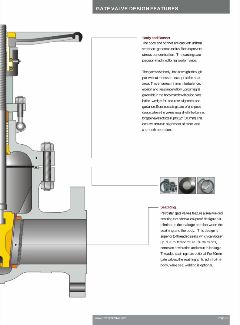
Body and Bonnet
The body and bonnet are cast with uniform
section and generous radius fillets to prevent
stress concentration. The castings are
precision-machined for high performance.
The gate valve body has a straight through
port without recesses except at the seat
area. This ensures minimum turbulence,
erosion and resistance to flow. Long integral
guide ride in the body match with guide slots
in the wedge for accurate alignment and
guidance. Bonnet castings are of one-piece
design, where the yoke is integral with the bonnet
for gate valves of sizes up to 12" (300mm). This
ensures accurate alignment of stem and
a smooth operation.
Seat Ring
Petrostar gate valves feature a seal-welded
seat ring that offers a leakproof design as i t
eliminates the leakage path bet ween the
seat ring and the body. This design is
superior to threaded seats which can loosen
up due to temperature fluctuations,
corrosion or vibration and result in leakage.
Threaded seat rings are optional, For 50mm
gate valves, the seat ring is f lared into the
body, while seal welding is optional.
www.petrostarvalve.com Page 36
GATE VALVE DESIGN FEATURES

Petrostar now offers standard cast steel bolted bonnetgate and globe valves qualification tested for compliancewith EPA fugitive emissions regulations
Ensures leakage of less than 100 ppm
as demonstrated through extensive
laboratory testing.
Large loads.
Sealing is achieved when compression load is
high and packing forms a mass of low porosity
and permeability (4,000 psi for graphite).
Small clearances between vital parts.
Precision stem and packing chambers.
Straightness, roundness and fine finish of stem
and packing chamber wall are essential.
Short and narrow packing chambers improve sealing.
Maximum six rings in a single set chamber and
wherever possible, only 1.4" wide.
Stem and packing chamber walls.
Close roundness, straightness and superior surface
finish of 6 RMS or better for the stem and 63 RMS
for the packing chamber.
The Petrostar stem seal evolved from
these test findings:
Standard Stem
Live-loading With leak-off
Live-loading. Two sets springs maintain
a permanent packing stress of 3500~4000 psi.
Live-loading extends low emission service life
especially in service with large pressure/
temperature transients or frequent cycling.
Leak-off.
For critical service a lantern ring and
double packing can be provided with a leak-off
connection. The leak-off is provided to allow
collection of leakage from the lower packing set.
Rings individually compressed in packing chamber
to 3500~4000 psi for graphite and 2,000 psi PTFE
to ensure equal stress distribution and effectiveness
of all rings.
LIVE-LOADING OPTIONS
GATE VALVE DESIGN FEATURES
www.petrostarvalve.com Page 37

Cast Carbon, Stainless or Alloy Steel Bolted Bonnet Gate Valves, 2-60" (50-1500 mm)ASME Class 150, 300, 600, 900 and 1500
DESIGN SPECIFICATIONS
ITEM APPLICABLE SPECIFICATION
DESIGN FEATURES:
Universal Trim. Petrostar provides
wide ranges of Trim material
including Trim 1 to very special
alloys.
Seat face Stellited, ground and
lapped to a mirror finish.
Flexible Wedge with low center
stem-wedge contact, in solid
13 CR or hard faced with
13 CR, SS 316, Monel or Stellite.
Wedge is ground and lapped to a
mirror finish and tightly guided to
prevent dragging and seat
damage. A Stellite 6 hard faced
CF8M wedge is also available.
Non-rotating stem with precision
Acme threads and burnished
finish. Double Acme for faster
operation.
Larger diameter valves are
provided with double bearing
on hand wheel for smooth
operation.
Pressure seal bonnet design
available in Class 900 and above
rating valves.
Body and bonnet castings are
precision machined. One-piece
bonnet up to 12" (300 mm) for
better alignment and fewer parts.
Gland has two-piece construction
for easy alignment.
Flanges:
Finish 125-250 AARH for all
valves.
Rotating stem nut is ASTM B 62
renewable in line. Thrust bearings
are supplied as follows:
150-300: 10-12" (250-300 mm),
1 bearing (top),
16" (400 mm) and up,
two bearings
600: 6" (150 mm) and up
900-1500: 6" (150 mm) and up.
GATE VALVE
www.petrostarvalve.com Page 38
Wall thickness and general valve design
Pressure-temperature rating
Face to face dimensions for butt weld and flanged valves
Flange design
Butt welding design
Test and Inspection
API 600, API 6D, BS1414
ASME B16.34
ASME B16.10
ASME B16.5
ASME B16.25
API 598

FLEXIBLE ROUND WEDGE PIONEERED BY PETROSTARCLASSICAL SOLID WEDGEON COMPETITIVE DESIGNS
Universal use for temperatures
up to 1000 F (538 C).
Flexibility compensates for seat
face distortion.
Compensates for deformation
of body due to pipe stresses.
Long cycle life.
Ideal for processes with large
temperature fluctuations.
Assures valve tightness on
both seats over wide range
of pressures.
Stem to wedge connection
is inside the seating faces
supporting the wedge ears
during opening.
More robust with less mass.
Wedge may cause severe jamming
at temperatures over 200 F (93 C).
Suitable for small valves
(1/2 -2", 15/50mm).
Wedge will stick when valve is
closed hot and allowed to cool.
No compensation for deformation
of body due to pressure temperature
or pipe stresses.
Difficult to make valve tight on both
seats due to seat face distortion.
SEAL WELDED SEATS VS SCREWED-IN SEATS
PETROSTAR STANDARD GROUND AND LAPPED SEAL WELDED SEATRINGS FACED WITH STELLITE 6
Welded-in leakproof.
Weld quality 100% tested.
Stable performance.
Ground and lapped to 2 RMS
finish after weld-in.
Standardized use for steam up
to 1000 F ( 538 C), oil an d ga s.
Easier to be replaced.
COMPETING SCREWED-IN SEATS
Can loosen up due to corrosion
and cause substantial leakage.
Replacement is difficult if not
impossible.
Threads can corrode and
cause leakage.
Seat is unsecured from
unscrewing.
Seat can become loose due to
temperature fluctuations, corrosion
or vibration, and can leak.
Not suitable for steam service.
Steam and other fluids will wire
draw body threads of loose seats
beyond repair.
www.petrostarvalve.com Page 39
CAST STEEL VALVE DESIGN FEATURES

www.petrostarvalve.com Page 40
CAST STEEL VALVE DESIGN FEATURES
Body Gasket of Gate, Globe and Check valve
For Class 300, Class 600
and Class 900
Structure 2:
For Class 150
Structure 3:
For Class 900, Class 1500
and Class 2500
Structure 1:

GATE VALVE DIMENSIONS AND WEIGHT
www.petrostarvalve.com Page 41
CLASS 150 (FIG NO. GB1--)
SIZE
L-RF
L-BW
L-RJ
H
W (HW)
W1(Gear)
Wt (HW)
Wt (Gear)
2
7.0
8.5
7.5
15.3
8
-
19
-
2.5
7.5
9.5
8.0
17.3
8
-
25
-
3
8.0
11.1
8.5
19.7
10
-
33
-
4
9.0
12
9.5
23.4
10
-
49
-
6
10.5
15.9
11
30.6
14
12.2
77
104
8
11.5
16.5
12
38.4
14
12.2
123
150
10
13
18
13.5
45.7
16
12.2
188
215
12
14
19.8
14.5
54.7
18
12.2
288
315
14
15
22.5
15.5
61.2
22
18.1
385
435
16
16
24
16.5
71.3
24
1.1
500
552
18
17
26
17.5
82.8
25
18.1
601
653
20
18
28
18.5
90.5
27
18.1
764
816
24
20.0
32.0
20.5
102.7
30
18.1
1007
1185
28
24.0
36.0
-
131
-
23.6
-
1880
30
24.0
36.0
-
142
-
23.6
-
2300
32
28.0
38.0
-
146
-
23.6
-
2550
36
28.0
40.0
-
154.5
-
23.6
-
3390
CLASS 300 (FIG NO. GB3--)
L-RF / L-BW
SIZE
L-RJ
H
W (HW)
W1 Gear
Wt (HW)
Wt. (Gear)
2
8.5
9.1
16.9
8
-
25
-
2.5
9.5
10.1
19.9
8
-
30
-
3
11.1
11.7
20.9
10
-
48
-
4
12.0
12.6
24.8
11
12.2
73
100
6
15.9
16.5
31.5
14
12.2
130
186
8
16.5
17.1
39.7
16
12.2
208
235
10
18.0
18.6
48.8
18
12.2
334
386
12
19.7
20.4
57.9
20
12.2
450
502
14
30.0
30.6
64.8
24
18.1
704
756
16
33.0
33.6
72.5
24
18.1
923
965
18
36.0
36.6
77.1
26
18.1
1131
1224
20
39.0
39.7
86.4
30
18.1
1345
1400
24
45.0
45.9
102.3
36
24
2122
2385
28
53.0
54.0
122.0
-
24
-
3300
30
55.0
56.0
130.7
-
24
-
3550
CLASS 600 (FIG NO. GB6--/ GP6--)
2
11.5
11.6
17.9
23.2
10
-
32
-
2.5
13.0
13.1
21.7
24.8
10
10
52
65
3
14.0
14.1
23.7
26.3
11.1
10
60
87
4
17.0
17.1
27.2
36
12
10
107
134
6
22.0
22.1
35.8
42.5
18
12.2
216
268
8
26.0
26.1
41.9
49.9
20
12.2
399
451
10
31.0
31.1
49.5
59.5
26
18.1
605
657
12
33.0
33.1
57.8
70.5
30
18.1
851
893
14
35.0
35.1
63.9
73.1
36
18.1
1177
1232
16
39.0
39.1
71.5
85.1
36
18.1
1513
1568
18
43.0
43.1
89.0
89.0
-
30
-
1980
20
47.0
47.3
106.5
106.5
-
30
-
2480
24
55.0
55.4
110.6
110.6
-
30
-
3850
SIZE
L-RF / L-BW
L-RJ
H (Bolted Bonnet)
H (P.S Bonnet)
W (HW)
W1 (Gear)
Wt (HW)
Wt (Gear)

www.petrostarvalve.com Page 42
BW= Butt weld
FL = Flanged
H = Center-to-Top,
Open
GATE VALVE DIMENSIONS AND WEIGHTS
Note: Weights mentioned are for Bolted bonnet type in Kgs. Other details are available on request.
CLASS 900 (FIG NO. GB9--/ GP9--)
2
14.50
14.62
19.7
23.4
11.1
-
70
-
2.5
16.50
16.62
21.7
29.6
11.1
10
110
1130
3
15.00
15.12
24.0
29.8
12
10
140
167
4
18.00
18.12
27.6
34.0
14
12.2
200
227
6
24.00
24.12
38.6
39.9
20
18.1
358
410
8
29.00
29.12
43.3
50.2
26
18.1
550
600
10
33.00
33.12
52.0
60.7
28
18.1
1000
1100
12
38.00
38.12
59.0
70.1
36
18.1
1215
1310
14
40.6
40.9
74.8
79.8
36
24
1600
1700
16
44.5
44.9
80.7
89.0
36
24
2150
2330
SIZE
L-RF / L-BW
L-RJ
H (Bolted Bonnet)
H (P.S Bonnet)
W (HW)
W1 (Gear)
Wt (HW)
Wt (Gear)
CLASS 1500 (FIG NO. GB15--/ GP15--)
2.5
16.50
16.62
22.1
29.6
12
10
124
158
3
18.50
18.62
24.4
29.8
14
10
175
202
4
21.50
21.62
28.7
36.0
16
12.2
270
300
6
27.75
28.00
39.4
48.0
20
18.1
520
575
8
32.75
33.13
44.5
51.6
30
18.1
820
915
10
39.00
39.38
65.4
64.8
36
24
1560
1750
12
44.50
45.12
72.44
77.8
36
24
1900
2120
14
49.5
50.2
-
-
24
-
2600
16
54.5
55.4
-
-
24
-
3450
SIZE
L-RF / L-BW
L-RJ
H (Bolted Bonnet)
H (P.S Bonnet)
W (HW)
W1 (Gear)
Wt (HW)
Wt (Gear)
2
14.50
14.62
20.1
23.4
11.1
-
75
99
CLASS 2500 (CP25--)
SIZE
L-RF / L-BW
L-RJ
H (P.S Bonnet)
W
Weight
2
17.75
17.87
27.56
14
135
2.5
20.00
20.25
29.53
18
210
3
22.75
23.00
34.92
18
271
4
26.50
26.88
43.19
20
650
6
36.00
36.50
57.09
24
1600
8
40.25
40.87
63.39
24
2450
10
50.00
50.88
81.73
24
4570
12
56.00
56.88
89.80
24
7150
H
W
L
L
H(o
pe
n)
W1

GLOBE VALVE
www.petrostarvalve.com Page 43
Cast Carbon, Stainless or Alloy Steel Bolted Bonnet Globe Valves, 2-16" (50-400 mm)ASME Class 150, 300, 600, 900 and 1500
DESIGN FEATURES:
Rotating Stem with precision ACME threads and burnished finish.
Valve suitable for horizontal installation.
Universal Trim.Petrostar provides wide ranges of Trim material
including Trim 1 to very special alloys.
Seat face Stellited, ground and lapped to a mirror finish.
Conical seat machined to 8 RMS.
Flat disc. Floating stem-disc engagement, hard faced with 13 CR,
Stellite 6, SS 316 or Monel, ground and lapped with seat. Disc in
SS 316 hard faced with Stellite 6 also available.
Tapered disc. Disc is guided by the mating surface of the seat,
hard faced with 13 CR, Stellite 6, SS 316 or Monel, ground and lapped
with seat. Disc in SS 316 hard faced with Stellite 6 also available.
2-6" (50-150 mm) valves may have solid 13 CR discs.
Body and bonnet. Castings are precision machined. One-piece
bonnet for better alignment, fewer parts. Stuffing box finish to 63
RMS or better.
Body and bonnet joint accurately machined. Fully enclosed gasket.
Gland has two-piece construction for easy alignment.
Rotating Stem nut. ASTM B62, renewable in-line.
Torque arm. To reduce wear on packing rings, to enable better sealing
and to reduce torque.
Impactor handwheels. Globe valves require higher closing torques than
gate valves with the same seat diameter and pressure class. The most
economical mechanism for tight shut off is the impact or handwheel.
Two lugs cast under the wheel strike simultaneous blows and give 3-10
times the closing force of standard hand wheels. Impact or hand wheels
are supplied at manufacturer's option unless specified by customer.
Soft Seated Plugs : Petrostar provides special Soft seated plugs for special
applications.
Pressure seal bonnet design available in Class 900 and above rating valves.
Larger diameter valves are provided with Double bearing on hand wheel
for smooth operation.
CONICAL SEAT
FLAT SEAT
Most sizes and pressure classes have
conical seats. Choice of flat or conical
seat is manufacturer's option unless
specified by customer.
Notes
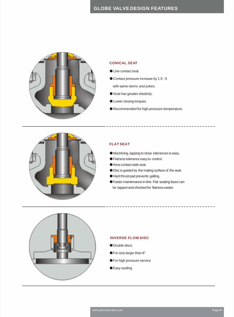
www.petrostarvalve.com Page 44
FLAT SEAT
CONICAL SEAT
Machining, lapping to close tolerances is easy.
Flatness tolerance easy to control.
Area contact wide seat.
Disc is guided by the mating surface of the seat.
Hard thrust pad prevents galling.
Faster maintenance in-line. Flat seating faces can
be lapped and checked for flatness easier.
Line contact seal.
Contact pressure increase by 1.5 - 5
with same stems and yokes.
Seat has greater elasticity.
Lower closing torques.
Recommended for high pressure-temperature.
Double discs
For size larger than 8"
For high pressure service
Easy sealing
INVERSE FLOW DISC
GLOBE VALVE DESIGN FEATURES

GLOBE VALVE DIMENSIONS AND WEIGHTS
www.petrostarvalve.com Page 45
CLASS 150 (FIG NO. LB1--)
SIZE
L-RF/ BW
L-RJ
H
W (HW)
W1 (Gear)
Wt (HW)
Wt (Gear)
2
8.00
8.50
12.9
8
-
22
-
2.5
8.50
9.00
14.17
10
-
32
-
3
9.50
10.00
15.94
10
-
38
-
4
11.50
12.00
19.09
12
-
62
-
6
16.00
16.50
20.47
14
-
104
-
8
19.50
20.00
23.62
16
16
154
174
10
24.50
25.00
31.00
18
16
308
330
12
27.50
28.00
33.94
20
18
539
575
14
31.00
31.50
53.00
22
20
819
855
16
36.00
36.50
61.00
24
24
1085
1185
18
38.50
39.00
70.00
32
30
1294
1394
CLASS 300 (FIG NO. LB3--)
SIZE
L-RF/ BW
L-RJ
H
W (HW)
W1 (Gear)
Wt (HW)
Wt (Gear)
2
10.50
11.13
13.78
8
-
28
-
2.5
11.50
12.13
15.39
10
-
48
-
3
12.50
13.13
16.54
12
-
56
-
4
14.00
14.63
19.37
14
-
82
-
6
17.50
18.13
24.41
18
16
154
178
8
22.00
22.63
31.22
22
20
240
270
10
24.50
25.13
45.08
25
22
319
352
12
28.00
28.63
49.61
28
24
632
672
14
33.00
33.63
55.28
32
30
946
1000
16
34.00
34.63
62.99
32
30
1243
1350
CLASS 600 (FIG NO. LB6--/ LP6--)
2
11.50
11.62
15.4
21.7
10
-
32
-
2.5
13.00
13.12
17.0
24.8
11
-
42
-
3
14.00
14.12
18.8
26.8
12
-
63
-
4
17.00
17.12
20.8
29.5
16
16
107
135
6
22.00
22.12
26.6
45.3
22
20
240
275
8
26.00
26.12
28.4
49.2
26
22
375
425
10
31.00
31.12
38.3
55.1
28
22
680
750
12
33.00
33.12
42.3
61.0
30
24
900
1000
SIZE
L-RF/ BW
L-RJ
H (Bolted Bonnet)
H (P.S Bonnet)
W (HW)
W1 (Gear)
Wt (HW)
Wt (Gear)

www.petrostarvalve.com Page 46
GLOBE VALVE DIMENSIONS AND WEIGHTS
H = Center-to-Top,
Open
DESIGN SPECIFICATIONS
ITEM APPLICABLE SPECIFICATION
Wall thickness and general valve design
Pressure-temperature rating
Face-to-face dimensions for butt weld and flanged valves
Flange design
Butt welding design
Test and Inspection
BS 1873, ASME B 16.34
ASME B16.34
ASME B16.10
ASME B16.5
ASME B16.25
API 598
SIZE
L-RF/ BW
L-RJ
H (Bolted Bonnet)
H (P.S Bonnet)
W (HW)
W1 (Gear)
Wt (HW)
Wt (Gear)
CLASS 900 (FIG NO. LB9--/ LP9--)
2
14.50
14.62
19.6
24.4
12.4
-
55
-
2.5
16.50
16.62
20.0
25.3
12.4
-
68
-
3
15.00
15.12
20.6
28.4
14
12
95
128
4
18.00
18.12
23.7
33.5
16
15
138
175
6
24.00
24.12
28.8
48.2
22
20
390
460
8
29.00
29.12
38.20
53.1
26
22
774
850
10
33.00
33.12
52.40
61.0
38.3
24
1250
1325
12
38.00
38.12
61.00
68.9
38
28
1535
1625
SIZE
L-RF/ BW
L-RJ
H (Bolted Bonnet)
H (P.S Bonnet)
W (HW)
W1 (Gear)
Wt (HW)
Wt (Gear)
CLASS 1500 (FIG NO. LB15--/ LP 15--)
2
14.50
14.62
22.4
24.4
16
14
73
105
2.5
16.50
16.62
25.5
25.3
16
14
130
178
3
18.50
18.62
28.5
28.4
20
20
151
201
4
21.50
21.62
32.75
33.5
24
22
172
235
6
27.75
28.00
40.15
48.2
28
25
467
540
8
32.75
33.12
46.53
53.1
34
25
1225
1325
10
39.00
39.38
53.0
61.0
48
30
1635
1750
CLASS 2500 (FIG NO. LP25--)
2
17.75
17.87
28.35
16
176
2.5
20.00
20.25
31.50
20
264
3
22.75
23.00
34.84
22
308
4
26.50
26.88
49.61
25
759
6
36.00
36.50
75.00
25
1990
8
40.25
40.87
97.05
25
4390
Size
L-RF/ BW
L-RJ
H (Pressure seal)
W
Weight

www.petrostarvalve.com Page 47
Cast Cryogenic Gate, Globe and Check ValvesAustenitic Stainless Steel 2-30" (50-750 mm)Pressure Class 150-1500
The production, transport and storage of liquefied gases such as
oxygen, nitrogen, argon, natural gas, hydrogen or helium (down to -
425 F), p resents s everal t echnical p roblems. P etrostar s pecially-adapted
extended bonnet cast valves offer safe and efficient service.
MATERIALS:
Body and bonnet: Austenitic stainless steel castings used for bodies and
bonnets offer excellent impact strength, minimal heat loss and protection
against corrosion.
Stem: Austenitic stainless steel. To reduce galling, stems are also offered
in A479 grade XM-19 with high tensile strength even at extreme low
temperatures, excellent low friction and galling-free movement at points
of stem contact.
Wetted parts: All Austenitic stainless steel and Stellite 6.
Stem nut/yoke bushing: ASTM B62.
Packing: PTFE or graphite packing protected from freezing by a column
of insulating gas.
Seating faces: Stellite 6 is used to prevent seizing and galling. When
extremely tight shut off is required, globe and check valves are supplied
with Neoflon, PTFE or other soft inserts.
Bolting: Strain-hardened Austenitic stainless steel.
DESIGN FEATURES:
Extended bonnets with sufficient gas column length, usually specified by
customer, are supplied for all valves to keep stem packing at sufficient
distance away from the cold fluid to remain functional.
Flexible wedges with Stellite seating faces for cryogenic service(gate valve).
Neoflon inserts are available for globe, piston, and swing check discs.
Cleaning: All cryogenic valves are thoroughly de greased and cleaned and
pipe ends are sealed to prevent contamination.
Type
Boiling Point Liquid Density
Ib/ft.3C F
TABLE OF LIQUEFIED GASES
Natural gas(LNG)
Methane(CH4)
Oxygen(O2)
Argon(Ar)
Carbon Dioxide(CO2)
-168
-161.5
-182.9
-185.9
-78.5
-270
-258
-296
-303
-109
26
26.20
71.20
87.40
50.60
Type
Air
2Nitrogen(N )
Hydrogen(H2)
Helium(He)
Absolute zero
Boiling Point Liquid Density
Ib/ft.3C F
-194.4
-195.8
-252.8
-268.9
-273.16
-318
-320
-423
-452
- 460
57.87
50.45
4.43
7.82
-
CRYOGENIC VALVE

www.petrostarvalve.com Page 48
CHECK VALVE
Cast Carbon, Stainless or Alloy SteelSwing Check Valves , 2-36" (50-900 mm)ASME Class 150, 300, 600, 900 and 1500
Body and cover. Precision machined
castings.
Body and cover joint. Accurately
machined,fully enclosed gasket
Disc. Robust one-piece construction
to withstand the severe shock of check
valve service. Hard faced with 13 CR,
Stellite 6, SS 316, or Monel, ground
and lapped to mirror finish. Sizes
2-6" (50-150 mm) may have solid13
CR disc.
DESIGN FEATURES:
Disc assembly. Disc is fastened securely
to disc hanger with a lock nut and cotter
pin. Disc is free to rotate to avoid
localized wear. Disc hanger is supported
on a sturdy disc carrier hinge pin of
excellent bearing qualities. All parts are
accessible from top for easy servicing.

www.petrostarvalve.com Page 49
CHECK VALVE DIMENSIONS AND WEIGHTS
CLASS 150 (FIG NO. CB1--)
SIZE
L-RF/ BW
L-RJ
H
Weight Kgs.
2
8.00
8.50
6.10
19
2.5
8.50
9.00
6.70
26
3
9.50
10.00
7.10
29
4
11.50
12.00
8.66
46
6
14.00
14.50
10.55
77
8
19.50
20.00
12.20
163
10
24.50
25.00
13.70
220
12
27.50
28.00
14.90
356
14
31.00
31.50
15.80
428
16
34.00
34.50
18.10
555
18
38.50
39.00
19.85
775
20
38.50
39.00
22.20
835
24
51.00
51.50
26.75
1180
30
60.00
60.50
36.00
1725
36
77.00
77.50
41.50
2800
CLASS 300 (FIG NO. CB3--)
2
10.50
11.13
6.30
21
2.5
11.50
12.13
7.45
30
3
12.50
33.13
7.83
39
4
14.00
14.63
8.95
69
6
17.50
18.13
10.95
125
8
21.00
21.63
12.70
210
10
24.50
25.13
15.05
307
12
28.00
28.63
17.10
450
14
33.00
33.63
20.10
680
16
34.00
34.63
20.50
840
18
38.50
39.13
22.50
1025
20
40.00
40.75
24.75
1320
24
53.00
53.88
28.00
1960
30
62.75
63.75
37.00
2515
36
82.00
83.00
43.00
4515
SIZE
L-RF/ BW
L-RJ
H
Weight Kgs.
CLASS 600 (FIG NO. CB6--/ CP6)
2.5
13.00
13.13
7.90
10.4
50
3
14.00
14.13
8.95
10.6
70
4
17.00
17.13
10.25
12.5
122
6
22.00
22.13
12.80
15.7
270
8
26.00
26.13
15.50
23.1
465
10
31.00
31.13
19.30
23.9
675
12
33.00
33.13
20.80
27.4
880
14
35.00
35.13
22.60
29.5
950
16
39.00
39.13
26.00
28.7
1230
18
43.00
43.13
28.40
28.7
1635
20
47.00
47.25
29.40
32.2
2140
24
55.00
55.38
38.00
32.2
3200
SIZE
L-RF/ BW
L-RJ
H (Bolted Cover)
H (P.S Cover)
Weight Kgs.
2
11.50
11.63
7.20
9.5
36
CLASS 900 (FIG NO. CB9--/ CP9)
SIZE
L-RF/ BW
L-RJ
H (Bolted Cover)
H (P.S Cover)
Weight Kgs.
2
14.50
14.63
10.50
10.5
70
2.5
16.50
16.62
11.50
11.5
110
3
15.00
15.13
11.50
11.50
100
4
18.00
18.13
12.10
12.5
150
6
24.00
24.13
13.30
15.7
305
8
29.00
29.13
18.20
23.1
510
10
33.00
33.13
19.75
23.9
810
12
38.00
38.13
22.90
27.4
1120
14
40.50
40.87
25.60
29.5
1733
16
44.50
44.87
28.00
28.7
2395
18
48.00
48.50
31.00
32.0
3220
20
52.00
52.50
33.50
34.2
3960
24
61.00
61.75
36.80
38.0
5750

www.petrostarvalve.com Page 50
ITEM APPLICABLE SPECIFICATION
H = Center-to-Top,
Open
H
L(RT)
CHECK VALVE DIMENSIONS AND WEIGHTS
CLASS 1500 (FIG NO. CB15--/ CP15)
SIZE
L-RF/ BW
L-RJ
H (Bolted Cover)
H (P.S Cover)
Weight Kgs.
2
14.50
14.63
10.50
10.5
85
2.5
16.50
16.62
11.81
11.5
120
3
18.50
18.63
11.60
11.60
150
4
21.50
21.63
14.00
14.5
245
6
27.75
28.00
18.35
19.0
550
8
32.75
33.13
21.30
22.2
1010
10
39.00
39.37
22.80
23.9
1550
12
44.50
45.12
26.50
27.4
2280
14
49.50
50.25
28.70
29.5
3210
16
54.50
55.37
32.00
33.2
4365
18
60.50
61.37
35.65
36.2
5877
20
65.50
66.37
39.80
39.8
7260
24
76.50
77.63
44.50
44.5
10470
CLASS 2500 (FIG NO. CP2500)
SIZE
L-RF/ BW
L-RJ
H
Weight Kgs.
2
17.75
17.87
16.40
145
2.5
20.00
20.25
16.50
240
3
22.75
23.00
17.40
330
4
26.50
26.88
19.00
650
6
36.00
36.50
20.30
1400
8
40.25
40.87
28.10
2420
10
50.00
50.88
33.60
3750
12
56.00
56.88
39.50
5500
Note: Weights mentioned are for Bolted bonnet type. Other details are available on request.
DESIGN SPECIFICATIONS
Wall thickness and general valve design
Pressure-temperature rating
Face-to-face dimensions for butt weld and flanged valves
Flange design
Butt welding design
Test and Inspection
API 6D, BS 1868
ASME B16.34
ASME B16.10
ASME B16.5
ASME B16.25
API 598

SLAB GATE VALVE
Cast Carbon, Stainless or Alloy SteelSlab Gate Valve , 2-36" (50-900 mm)ASME Class 150, 300 and 600
For metal seated, sealant injection is
applied to ensure zero leakage.
Smaller torque and low flow resistance
compared to common gate valve.
Fully open port, convenient for pipe
cleaning.
DESIGN FEATURES
www.petrostarvalve.com Page 51

www.petrostarvalve.com Page 52
DESIGN SPECIFICATIONS
ITEM APPLICABLE SPECIFICATION
Wall thickness and general valve design
Pressure-temperature rating
Face to face dimensions for butt weld and flanged valves
Flange design
Butt welding design
Test and Inspection
API 600, API 6D, BS1414
ASME B16.34
ASME B16.10
ASME B16.5
ASME B16.25
API 598
SIZE Flange
CLASS 150
inmm
H = Center-to-Top,
Open
L
H
L
DIMENSIONS OF SLAB GATE VALVE WITH PILOT PORT
DoH
3
127
140
165
178
190
203
229
267
292
330
356
381
406
432
457
508
610
660
711
811
1
1-1/4
1-1/2
2
2-1/2
3
4
6
8
10
12
14
16
18
20
24
28
32
36
40
Hand-operated
H Do
360
375
410
450
550
610
700
895
1130
1290
1480
1660
1850
2080
2300
2680
3080
3491
3897
4317
180
180
250
250
300
300
300
350
350
400
450
500
500
600
700
800
800
1000
1000
1200
Geared driving
-
-
-
-
-
-
BA-0
BA-0
BA-0
BA-0
BA-0
BA-1
BA-1
BA-1
BA-1
BA-2
BA-2
BA-2
BA-3
BA-3
Non-diversion Hole type
H3
60
71
75
85
91
109
121
178
211
215
245
280
310
346
363
442
505
560
610
715
Diversionhole type
H1
85
103
115
122
154
169
193
283
352
440
514
602
678
785
855
1045
1190
1350
1510
1715

B
A
BW= Butt weld
FL = Flanged
H = Center-to-Top,
Open
DIMENSIONS OF SLAB GATE VALVE WITHOUT PILOT PORT
www.petrostarvalve.com Page 53
H3
SIZE Flange
CLASSES 300
inmm L
165
178
190
216
241
283
305
403
419
457
502
762
838
914
991
1143
1346
1524
1727
1
1-1/4
1-1/2
2
2-1/2
3
4
6
8
10
12
14
16
18
20
24
28
32
36
Hand-operated
H Do
370
385
420
458
555
615
710
900
1135
1401
1580
-
-
-
-
-
-
-
-
180
180
250
250
300
300
300
350
350
400
450
-
-
-
-
-
-
-
-
Geared driving
-
-
-
-
-
-
BA-0
BA-0
BA-0
BA-0
BA-0
BA-1
BA-1
BA-1
BA-1
BA-2
BA-2
BA-2
BA-3
Non-diversion Hole type
H3
70
80
85
100
106
124
146
206
241
251
281
325
360
400
430
497
560
620
610
Diversionhole type
H1
90
115
130
137
169
184
218
311
382
476
545
645
728
800
930
1100
1260
1420
1510
SIZE Flange
CLASSES 600
inmm L
292
330
356
432
559
660
787
838
889
991
1092
1194
2
2-1/2
3
4
6
8
10
12
14
16
18
20
Hand-operated
H Do
468
565
625
720
910
1145
1411
1590
-
-
-
-
300
300
350
350
400
500
500
600
-
-
-
-
Geared driving
BA-0
BA-0
BA-0
BA-0
BA-0
BA-1
BA-1
BA-1
BA-2
BA-2
BA-2
BA-2
Non-diversion Hole type
H3
108
125
145
165
220
280
330
380
430
480
530
580
Diversionhole type
H1
158
190
225
255
330
410
490
570
650
735
810
905
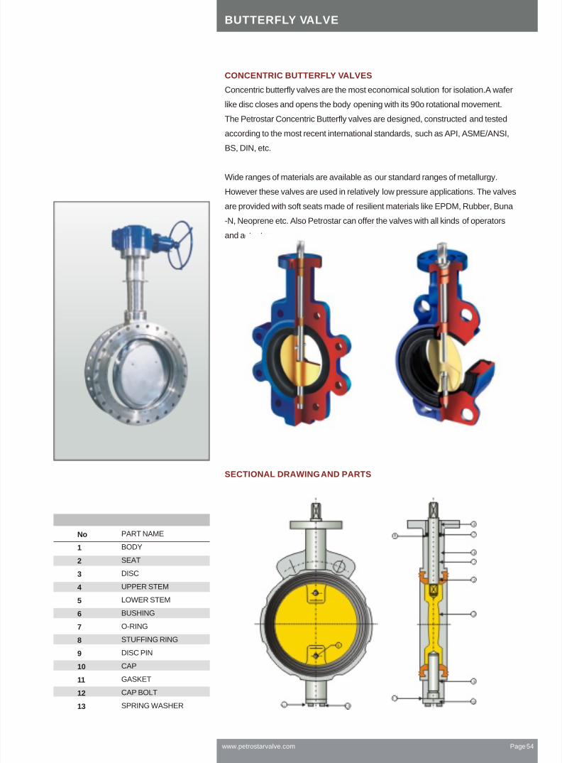
www.petrostarvalve.com Page 54
BUTTERFLY VALVE
Concentric butterfly valves are the most economical solution for isolation.A wafer
like disc closes and opens the body opening with its 90o rotational movement.
The Petrostar Concentric Butterfly valves are designed, constructed and tested
according to the most recent international standards, such as API, ASME/ANSI,
BS, DIN, etc.
Wide ranges of materials are available as our standard ranges of metallurgy.
However these valves are used in relatively low pressure applications. The valves
are provided with soft seats made of resilient materials like EPDM, Rubber, Buna
-N, Neoprene etc. Also Petrostar can offer the valves with all kinds of operators
and actuators
CONCENTRIC BUTTERFLY VALVES
SECTIONAL DRAWING AND PARTS
PART NAME
BODY
SEAT
DISC
UPPER STEM
LOWER STEM
BUSHING
O-RING
STUFFING RING
DISC PIN
CAP
GASKET
CAP BOLT
SPRING WASHER
No
1
2
3
4
5
6
7
8
9
10
11
12
13
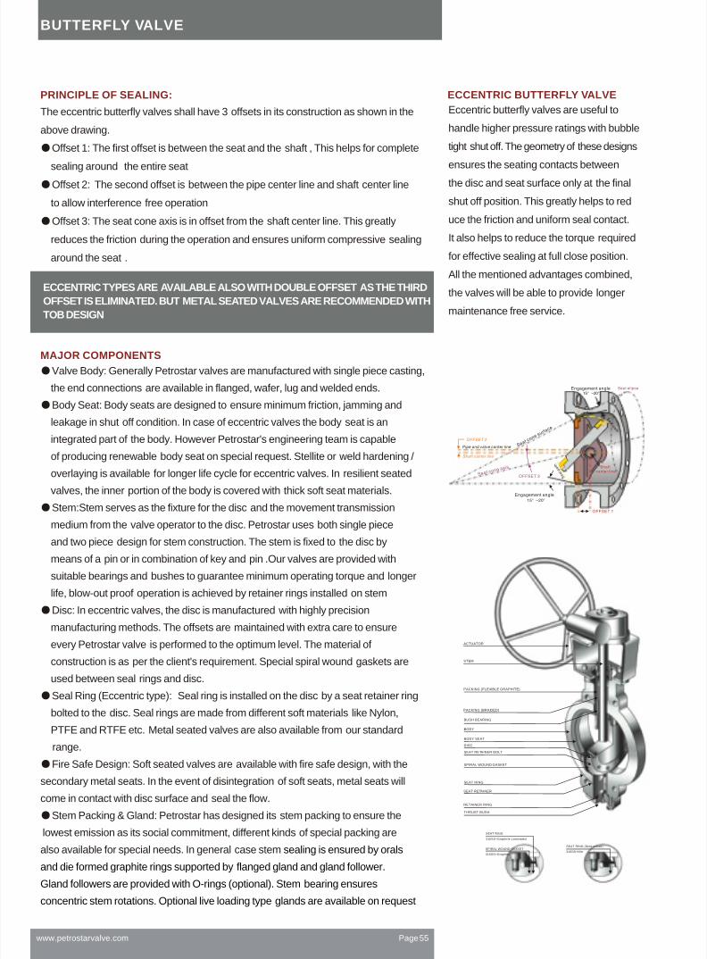
BUTTERFLY VALVE
Eccentric butterfly valves are useful to
handle higher pressure ratings with bubble
tight shut off. The geometry of these designs
ensures the seating contacts between
the disc and seat surface only at the final
shut off position. This greatly helps to red
uce the friction and uniform seal contact.
It also helps to reduce the torque required
for effective sealing at full close position.
All the mentioned advantages combined,
the valves will be able to provide longer
maintenance free service.
The eccentric butterfly valves shall have 3 offsets in its construction as shown in the
above drawing.
PRINCIPLE OF SEALING:
Offset 1: The first offset is between the seat and the shaft , This helps for complete
sealing around the entire seat
Offset 2: The second offset is between the pipe center line and shaft center line
to allow interference free operation
Offset 3: The seat cone axis is in offset from the shaft center line. This greatly
reduces the friction during the operation and ensures uniform compressive sealing
around the seat .
Valve Body: Generally Petrostar valves are manufactured with single piece casting,
the end connections are available in flanged, wafer, lug and welded ends.
Body Seat: Body seats are designed to ensure minimum friction, jamming and
leakage in shut off condition. In case of eccentric valves the body seat is an
integrated part of the body. However Petrostar's engineering team is capable
of producing renewable body seat on special request. Stellite or weld hardening /
overlaying is available for longer life cycle for eccentric valves. In resilient seated
valves, the inner portion of the body is covered with thick soft seat materials.
Stem:Stem serves as the fixture for the disc and the movement transmission
medium from the valve operator to the disc. Petrostar uses both single piece
and two piece design for stem construction. The stem is fixed to the disc by
means of a pin or in combination of key and pin .Our valves are provided with
suitable bearings and bushes to guarantee minimum operating torque and longer
life, blow-out proof operation is achieved by retainer rings installed on stem
Disc: In eccentric valves, the disc is manufactured with highly precision
manufacturing methods. The offsets are maintained with extra care to ensure
every Petrostar valve is performed to the optimum level. The material of
construction is as per the client's requirement. Special spiral wound gaskets are
used between seal rings and disc.
Seal Ring (Eccentric type): Seal ring is installed on the disc by a seat retainer ring
bolted to the disc. Seal rings are made from different soft materials like Nylon,
PTFE and RTFE etc. Metal seated valves are also available from our standard
range.
Fire Safe Design: Soft seated valves are available with fire safe design, with the
secondary metal seats. In the event of disintegration of soft seats, metal seats will
come in contact with disc surface and seal the flow.
Stem Packing & Gland: Petrostar has designed its stem packing to ensure the
lowest emission as its social commitment, different kinds of special packing are
also available for special needs. In general case stem sealing is ensured by orals
and die formed graphite rings supported by flanged gland and gland follower.
Gland followers are provided with O-rings (optional). Stem bearing ensures
concentric stem rotations. Optional live loading type glands are available on request
MAJOR COMPONENTS
ECCENTRIC TYPES ARE AVAILABLE ALSO WITH DOUBLE OFFSET AS THE THIRD
OFFSET IS ELIMINATED. BUT METAL SEATED VALVES ARE RECOMMENDED WITH
TOB DESIGN
ECCENTRIC BUTTERFLY VALVE
www.petrostarvalve.com Page 55
SEAT RING
316SS+Graphrte Laminated
SPIRAL WOUND GASKET
316SS+Graphrte
SEAT RING (Solid metall)
316SS+Nitr
PACKING (FLEXIBLE GRAPHITE)
PACKING (BRAIDED)
BUSH BEARING
BODY
BODY SEAT
DISC
SEAT RETAINER BOLT
SPIRAL WOUND GASKET
SEAT RING
SEAT RETAINER
RETAINER RING
THRUST BUSH
ACTUATOR
STEM

www.petrostarvalve.com Page 56
VALVE DIMENSIONAL DRAWINGS
Wafer Type Design Lug Type Design
Double Flange Design
Mounting Base
C1
n- h2 HOLE
Mounting Base
EACH SIDE4- H TAP DP
4- h1 HOLEC:BOLT CIRCLE
A A"
EACH SIDE4- h TAP DP
C:BOLT CIRCLE
A A"
EACH SIDE4- H TAP DP
4- h1 HOLEC:BOLT CIRCLE
A A"
n1- h1 HOLE
LL
SECTION A-A"
L
SECTION A-A"
HIGH PRESSUREFLOW
HIGH PRESSUREFLOW
H2
AP
PR
OX
H
H1
STEM SIDE DISC SIDE
Do
AP
PR
OX
H
H1
H2
Parts
1 Body
2 Sea t surface
3 Disc
4 Stem
5 Retainer ring
6 Packing
7 Packing gland
8 Gland flange
9 Gland bolt
10 Nut
11 Bush bearing
12 Key
13 Seal ring
14 Taper pin
15 Yoke
16 Yoke bolt
17 Yoke nut
nut
18 Mounting bolt
19 Spring washer
20 Key
21 Gear box
22 Cap
23 Gasket (cap)
24 Thrust bush
25 Seat retainer
26 Retainer bolt
27 Bush bearing
28 Gasket
29 Handwheel
30 Cap bolt
31 Cap nut
32 Seal ring pin
33 Spacer
BUTTERFLY VALVE

www.petrostarvalve.com Page 57
Size
Inch W & L
48
54
57
57
64
71
81
92
102
114
127
154
Flanged
114
127
140
140
152
165
178
190
216
222
229
267
C
152.4
190.5
215.9
241.3
298.4
361.9
431.8
476.3
539.7
577.8
635
749.3
h1
19.1
19.1
22.2
22.2
22.2
25.4
25.4
28.6
28.6
31.8
31.8
35.1
D*
191
229
254
279
343
406
483
533
597
635
699
813
g*
127.0
157.2
185.7
215.9
269.7
323.9
381.0
412.8
469.9
533.4
584.2
692.2
n1^
4
8
8
8
8
12
12
12
16
16
20
20
H
282
294
319
340
384
434
520
544
643
660
695
813
H1
258
270
295
316
344
394
470
494
578
595
630
743
H2
142
162
170
179
208
241
267
316
349
381
412
473
Type
F07
F07
F07
F07
F10
F10
F14
F14
F16
F16
F16
F25
C1
70
70
70
70
102
102
140
140
165
165
165
254
n
4
4
4
4
4
4
4
4
4
4
4
8
h2
9
9
9
9
11
11
18
18
22
22
22
18
Wafer
21
27
32
35
53
74
95
131
165
230
280
450
Lug
23
30
36
39
59
83
110
153
193
258
318
507
Flange
27
35
41
45
68
97
133
188
238
302
380
599
F to F - mm Flange Dimensions - mm Height - mm Mounting Base - mm Weight (Kgs)
DIMENSIONAL DETAILS CLASS 150 VALVES
* Only applicable for Double Flanged design ^ Only applicable for Lug and Flanged Design
3
4
5
6
8
10
12
14
16
18
20
24
Size
Inch
F to F - mm Flange Dimensions - mm Height - mm Mounting Base - mm Weight (Kgs)
DIMENSIONAL DETAILS CLASS 300 VALVES
W & L
48
54
59
59
73
83
92
117
133
149
159
181
Flanged
114
127
140
140
152
165
178
190
216
222
229
267
C
168.2
200.0
234.9
269.8
330.2
387.3
450.8
514.3
571.5
628.6
685.8
812.8
h1^
22.2
22.2
22.2
22.2
25.4
28.6
31.8
31.8
35.1
35.1
35.1
41.2
D*
210
254
279
318
381
445
521
584
648
711
775
814
g*
127.0
157.2
185.7
215.9
269.7
323.9
381.0
412.8
469.9
533.4
584.2
692.2
n1^
4
8
8
8
8
12
12
12
16
16
20
20
H
282
294
319
375
450
499
562
616
676
711
798
914
H1
258
270
295
336
400
449
497
551
606
641
721
837
H2
142
162
170
199
227
265
302
328
367
402
432
530
Type
F07
F07
F10
F10
F14
F14
F16
F16
F25
F25
F30
F30
C1
70
70
102
102
140
140
165
165
254
254
298
298
n
4
4
4
4
4
4
4
4
8
8
8
8
h2
9
9
9
9
11
11
18
18
22
22
22
18
Wafer
21
27
38
45
72
135
148
208
298
382
450
680
Lug
24
32
44
52
83
151
172
249
352
449
534
812
Flange
29
39
52
63
101
176
210
315
440
558
670
1025
3
4
5
6
8
10
12
14
16
18
20
24
Size
Inch
F to F - mm Flange Dimensions - mm Height - mm Mounting Base - mm Weight (Kgs)
DIMENSIONAL DETAILS CLASS 600 VALVES
W & L
54
64
78
78
102
117
140
Flanged
180
190
200
210
230
250
270
C
168.2
215.9
266.7
292.1
349.2
431.8
488.9
h1^
22.2
25.4
28.6
28.6
31.8
35.1
35.1
D*
210
273
330
356
419
508
559
g*
127.0
157.2
185.7
215.9
269.7
323.9
381.0
n1^
8
8
12
12
12
16
20
H
289
370
405
420
490
545
630
H1
265
330
365
370
425
480
560
H2
148
180
195
225
255
310
330
Type
F07
F10
F14
F14
F16
F16
F25
C1
70
102
140
140
165
165
254
n
4
4
4
4
4
4
8
h2
9
11
18
18
22
22
18
Wafer
29
38
55
75
136
200
295
Lug
32
45
67
88
157
237
335
Flange
37
55
86
109
192
296
390
3
4
5
6
8
10
12
STANDARDS OF DESIGN
Valve Construction Design Confirmed to API 609
Hydro Testing API 598
Fire Safe Design API 607 Ed 4
End Connections Flanged, Wafer, Lug and Welded
Dimension Standards API 609 table 2, MSS-SP-68 Table 1, ISO 5752
ASME B16.5, B16.47, B16.34, DIN, MSS-SP-44, BS3293
Mounting Flange ISO 5211
BUTTERFLY VALVE DIMENSIONS AND WEIGHTS

Petrostar forged steel valves contain
gate, globe & check valves. We offer
standard bolted bonnet with optional
welded bonnet and pressure sealed
bonnet.
Petrostar also offers globe valve with
bellow seal. Stellited seating face is also
available with Petrostar forged valves.
Forged steel valves can be furnished with
nipples.
Products Range:
Type:Gate, Globe Check
Size: 1/2 "~2"
Rating:
150Lb,300Lb,600Lb,900Lb
800Lb ,1500Lb,2500Lb
Body Material:
A105,F11,F22,F5,F316,F304
End connection:
NPT, SW, R F ,BW
Design Feature:
Solid wedge(gate)
Bolted, welded or pressure sealed bonnet
Full port or reduced port
Optional bellow seal(gate, globe
Plug disc with optional needle disc(globe)
Lift check with optional swing check (check)
Body and Bonnet
FORGED STEEL VALVE
www.petrostarvalve.com Page 58
Y type globe valve available.

Os&y, Rising Stem, Solid wedge,Bolted bonnet, Screwed or Socket Weld End
FORGED STEEL GATE VALVE
No Part Name Standard Low Temp.
NACE
7 Gasket304+
Graphite
316+
Graphite
B7
2H
410
L7M
2HM
304
www.petrostarvalve.com Page 59
Material of Parts
BodyBonnetStemDiscSeat RingBonnet Bolt
123456
89101112131415161718
GlandPackingGland FlangeGland BoltGland Bolt NutGland Bolt PinSleeveSleeve WasherHandwheelNameplateHandwheel Nut
A105A105F6F6F6-HFSB7
LF2LF2316316316-HFSL7M
F6 316GraphiteWCB
410410A197AluminumA108-1020
304(L)304(L)304(L)304(L)304-STLB8(M)304+Graphite304
B8(M)8(M)410
316(L)316(L)316(L)316(L)316-STLB8(M)316+Graphite316
B8(M)8(M)410
Design: BS 5352, API 602
SW dimension: ANSI B 16.11
NPT dimension: ANSI B 1.20.1
BW dimension: ANSI B 16.25
Flange dimension: ANSI B 16.5
Stainless Steel
NACE

www.petrostarvalve.com Page 60
Nominal Diameter d (mm) L (mm) H(Open,mm) W(mm) Weight(kgs)R F
Diameter d (mm) L (mm) H(Open,mm) Weight(kgs)
FORGED STEEL GATE VALVE DIMENSIONS AND WEIGHTS
CLASS 800
15(1/2")
20(3/4")
25(1")
32(1-1/4")
40(1-1/2")
50(2")
65(2-1/2")
80(3")
10(3/8")
15(1/2")
20(3/4")
25(1")
32(1-1/4")
40(1-1/2")
50(2")
65(2-1/2")
10
13.6
18
24
29
36.8
46.5
51
79
92
111
120
120
140
178
185
161
163
196
223
251
290
330
370
100
100
125
160
160
180
200
220
2.22
2.39
4.29
5.70
7.05
10.9
16.8
24
Nominal Diameter d (mm) L (mm) H(Open,mm) W(mm) Weight(kgs)R F
CLASS 1500
10.5
13.5
18
24
29
36.8
45
111
111
120
120
140
178
180
191
192
219
243
296
316
370
125
125
160
160
180
200
200
4.4
5.1
6
7.2
11.4
16
23
15(1/2")
20(3/4")
25(1")
32(1-1/4")
40(1-1/2")
50(2")
60(2-1/2")
10(3/8")
15(1/2")
20(3/4")
25(1")
32(1-1/4")
40(1-1/2")
50(2")
F
CLASS 2500
14
14
19
-
30
30
150
150
210
-
235
235
293
300
390
-
435
435
130
130
250
-
300
300
11
11.3
22.4
-
38
38
15(1/2")
20(3/4")
25(1")
-
40(1-1/2")
50(2")
W(mm)
d
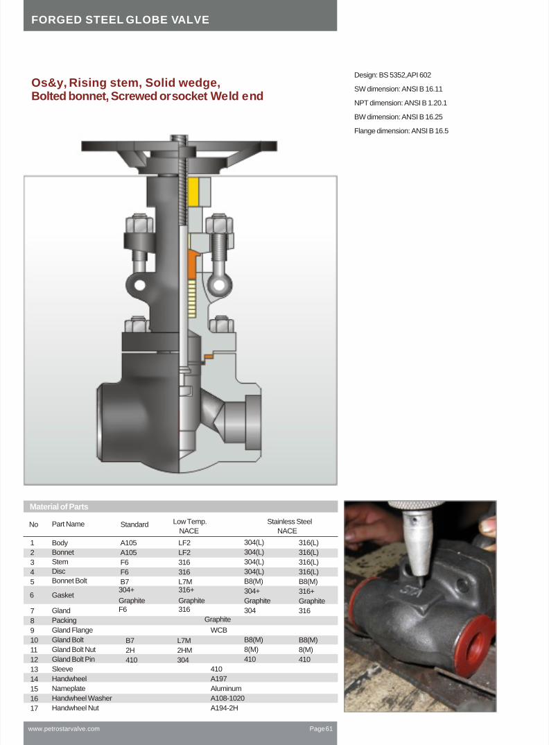
FORGED STEEL GLOBE VALVE
www.petrostarvalve.com Page 61
No Part Name Standard Low Temp.
NACE
B7
2H
410
L7M
2HM
304
304(L)
304(L)
304(L)
304(L)
B8(M)
304+
Graphite
304
B8(M)
8(M)
410
316(L)
316(L)
316(L)
316(L)
B8(M)
316+
Graphite
316
B8(M)
8(M)
410
1
2
3
4
5
7
8
9
10
11
12
13
14
15
16
17
6
Body
Bonnet
Stem
Disc
Bonnet Bolt
Gland
Packing
Gland Flange
Gland Bolt
Gland Bolt Nut
Gland Bolt Pin
Sleeve
Handwheel
Nameplate
Handwheel Washer
Handwheel Nut
Gasket
A105
A105
F6
F6
B7
LF2
LF2
316
316
L7M304+
Graphite
316+
GraphiteF6 316
Graphite
WCB
410
A197
Aluminum
A108-1020
A194-2H
Design: BS 5352,API 602
SW dimension: ANSI B 16.11
NPT dimension: ANSI B 1.20.1
BW dimension: ANSI B 16.25
Flange dimension: ANSI B 16.5
Os&y, Rising stem, Solid wedge,Bolted bonnet, Screwed or socket Weld end
Stainless Steel
NACE
Material of Parts
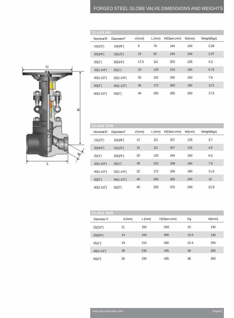
www.petrostarvalve.com Page 62
FORGED STEEL GLOBE VALVE DIMENSIONS AND WEIGHTS
Nominal Diameter d (mm) L (mm) H(Open,mm) W(mm) Weight(kgs)R F
Diameter d (mm) L (mm) H(Open,mm) W(mm)Kg
CLASS 800
Nominal Diameter d (mm) L (mm) H(Open,mm) W(mm) Weight(kgs)R F
CLASS 1500
F
CLASS 2500
15(1/2")
20(3/4")
25(1")
32(1-1/4")
40(1-1/2")
50(2")
60(2-1/2")
10(3/8")
15(1/2")
20(3/4")
25(1")
32(1-1/4")
40(1-1/2")
50(2")
9
13
17.5
23
30
35
46
79
92
111
120
152
172
200
164
164
203
224
260
300
355
100
100
125
160
160
180
200
2.28
2.37
4.3
5.75
7.8
12.5
17.5
12
15
20
28
32
40
45
111
111
120
152
172
200
220
207
207
240
258
330
355
370
125
125
160
160
180
200
240
3.7
4.6
6.5
7.6
11.6
15
21.9
15(1/2")
20(3/4")
25(1")
32(1-1/4")
40(1-1/2")
50(2")
60(2-1/2")
10(3/8")
15(1/2")
20(3/4")
25(1")
32(1-1/4")
40(1-1/2")
50(2")
15(1/2")
20(3/4")
25(1")
40(1-1/2")
50(2")
11
14
19
28
35
150
150
210
235
235
293
300
390
435
435
130
130
250
300
300
10
10.3
22.4
38
38

www.petrostarvalve.com Page 63
ASTM
Code
A105
A182F11
A182F22
A182F304
A182F304L
A182F316
A182F316L
A182F51
A182F6a
A193B7
A193B7M
A193B8
A193B8M
A193B16
A1942H
A1942HM
A1948
A1948M
A216WCB
A216WCC
A217C5
A217CA15
A217WC6
A217WC9
A276410
A276420
A320L7
A320L7M
A336F22
A350LF1
A350LF2
A351CF3
A351CF3M
A351CF8
A351CF8M
A351CF8C
A351CN7M
A352LC1
A352LC2
A352LC3
A352LCB
A352LCC
A439D2
0.35
0.08
0.030
0.08
0.030
0.030
0.15
0.08
0.08
0.40
0.40
0.08
0.08
0.30
0.25
0.20
0.15
0.15
0.30
0.30
0.03
0.03
0.08
0.08
0.08
0.07
0.25
0.25
0.15
0.30
0.25
3.00
2.00
2.00
2.00
2.00
2.00
1.00
2.00
2.00
1.00
1.00
2.00
2.00
1.00
1.20
1.00
1.00
1.00
1.50
1.50
1.50
1.50
1.50
1.50
1.00
1.20
0.035
0.030
0.040
0.045
0.045
0.045
0.045
0.030
0.040
0.035
0.035
0.045
0.045
0.035
0.040
0.040
0.045
0.045
0.04
0.04
0.04
0.040
0.04
0.04
0.040
0.040
0.035
0.035
0.025
0.035
0.035
0.040
0.040
0.040
0.040
0.040
0.040
0.04
0.04
0.04
0.04
0.04
0.08
0.040
0.030
0.040
0.030
0.030
0.030
0.030
0.020
0.030
0.040
0.040
0.030
0.030
0.040
0.050
0.050
0.030
0.030
0.045
0.045
0.045
0.040
0.045
0.045
0.030
0.030
0.040
0.040
0.025
0.040
0.040
0.040
0.040
0.040
0.040
0.040
0.040
0.045
0.045
0.045
0.045
0.045
0.50
1.00
1.00
1.00
1.00
1.00
1.00
1.00
1.00
0.04
0.04
1.00
1.00
0.60
0.60
0.75
1.50
0.60
0.60
1.00
1.00
0.50
2.00
1.50
2.00
1.50
2.00
1.50
0.60
0.60
0.60
0.60
0.60
0.40
0.30
0.30
0.50
0.50
0.50
0.40
0.40
03.0~4.0
0.30
0.08
0.03
0.03
0.08
0.08
0.03
0.03
0.02
0.02
0.02
485
415
415
515
485
515
485
620
585
860
690
515
515
860
480
860
690
485
485
485
485
485
425
400
250
205
205
205
170
205
170
450
380
720
550
205
205
720
250
275
415
450
275
275
275
725
550
310
205
250
205
205
205
205
2085
170
240
275
275
240
275
207
30
20
20
30
30
30
30
25
18
16
18
30
30
18
22
22
18
18
20
20
20
16
18
19
28
30
35.0
30.0
35.0
30.0
30.0
35
24
24
24
24
22
8.0
30
45
35
50
50
50
50
45
35
50
50
50
50
50
35
35
35
30
35
35
45
50
50
40
38
30
35
35
35
35
35
187
170
321
235
223
223
321
241
235
Avg:27;
min:20
Avg:27;
min:20
Avg:18;
min:14
Avg:20;
min:16
Avg:18;
min:14
Avg:20;
min:16
Avg:20;
min:16
Avg:18;
min:14
Avg:20;
min:16
Chemical Compositions % Mechanical Hardness Charpy
C Mn P S Si Cr Mo Ni VCu Nb Tensile
MPa,
Yield
MPa,
ElonGation
%,
Reduce
%,
J,Brinell
HB,
MATERIALS
MATERIALS
0.05~
0.15
0.05~
0.15
0.37~0.490.37~0.49
0.36~
0.47
0.05~
0.20
0.05~
0.18
0.08~
0.15
0.38~
0.048
0.38~
0.048
0.05~
0.15
0.60~
1.05
0.30~
0.60
0.30~
0.60
0.65~1.100.65~1.10
0.45~
0.70
0.40~
0.70
0.50~
0.80
0.40~
0.70
0.75~
1.00
0.75~
1.00
0.30~
0.60
0.60~
1.35
0.60~
1.35
0.50~
0.80
0.50~
0.80
0.50~
0.80
0.70~14.25
0.010~
0.35
0.50~
1.00
0.15~0.350.15~0.35
0.15~
0.35
0.15~
0.35
0.15~
0.358
0.15~
0.30
0.15~
0.30
1.50~
3.00
0.30
0.50
0.50
0.30
0.30
0.50
0.50
1.75~
2.75
1.00~1.50
2.00~2.5018.0~20.018.0~20.016.0~18.016.0~18.021.0~23.011.5~13.50.75~1.200.75~1.2018.0~20.016.0~18.00.80~1.15
18.0~20.016.0~18.0
4.00~6.5011.5~14.01.00~1.502.00~2.7511.5~13.512.0~14.00.80~1.100.80~1.102.00~2.50
1.70~
21.0
17.0~
21.0
18.0~
21.0
18.0~
21.0
18.0~
21.0
19.0~
22.0
0.12
0.20
0.2
0.50
0.12
0.12
0.50
0.50
0.50
0.20
0.20
2.0~
3.00
2.0~
3.00
2.0~
3.00
0.45~
0.65
0.44~
0.65
0.87~
14.13
2.00~
3.00
2.00~
3.00
2.5~
3.5
0.15~0.250.15~0.25
2.00~3.000.50~0.65
2.00~
3.00
0.45~
0.65
0.45~
0.65
0.90~
1.250
0.15~
0.25
0.15~
0.25
0.90~
1.10
0.4
0.50
0.50
0.50
0.50
1.00
0.50
0.40
0.40
0.50
0.50
8.0~
11.0
8.0~
13.0
10.0~
14.0
10.0~
15.0
4.5~
6.5
8.0~11.010.0~14.0
8.0~
11.0
10.0~
14.0
8.0~
12.0
9.0~
13.0
8.0~
11.0
9.0~
12.0
9.0~
12.0
27.5~
30.5
2.00~
3.00
3.00~
4.00
18.00~22.00
0.25~
0.35
485~655485~655620~795620~795485~655485~655
515~
690
415~
585
485~
655
450~
620
485~
655
485~
655
450~
620
485~
655
121~
174
167~
229
248~
352
159~
237
126~
300
126~
300
139~
202

ral 1000
ral 1011
ral 1019
ral 1033
ral 2009
ral 3004
ral 3015
ral 4001
ral 4009
ral 5008
ral 5017
ral 6000
ral 6008
ral 6016
ral 6025
ral 7000
ral 7008
ral 7021
ral 7033
ral 7042
ral 8007
ral 8019
ral 9003
ral 1001
ral 1012
ral 1020
ral 1034
ral 2010
ral 3005
ral 3016
ral 4002
ral 5000
ral 5009
ral 5018
ral 6001
ral 6009
ral 6017
ral 6026
ral 7001
ral 7009
ral 7022
ral 7034
ral 7043
ral 8008
ral 8022
ral 9004
ral 1007
ral 1018
ral 1032
ral 2008
ral 3003
ral 3014
ral 3031
ral 4008
ral 5007
ral 5015
ral 5024
ral 6007
ral 6015
ral 6024
ral 6034
ral 7006
ral 7016
ral 7032
ral 7040
ral 8004
ral 8017
ral 9002
ral 9018
ral 1006
ral 1017
ral 1028
ral 2004
ral 3002
ral 3013
ral 3027
ral 4007
ral 5005
ral 5014
ral 5023
ral 6006
ral 6014
ral 6022
ral 6033
ral 7005
ral 7015
ral 7031
ral 7039
ral 8003
ral 8016
ral 9017
ral 9001
ral 1002
ral 1021
ral 2000
ral 2011
ral 3007
ral 3017
ral 4003
ral 5001
ral 5010
ral 5019
ral 6002
ral 6010
ral 6018
ral 6027
ral 7001
ral 7010
ral 7023
ral 7035
ral 7044
ral 8011
ral 8023
ral 9005
ral 1013
ral 1003
ral 1023
ral 2001
ral 2012
ral 3009
ral 3018
ral 4004
ral 5002
ral 5011
ral 5020
ral 6003
ral 6011
ral 6019
ral 6028
ral 7002
ral 7011
ral 7024
ral 7036
ral 8000
ral 8012
ral 8024
ral 1014
ral 9010
ral 1004
ral 1024
ral 2002
ral 3000
ral 3011
ral 3020
ral 4005
ral 5003
ral 5012
ral 5021
ral 6004
ral 6012
ral 6020
ral 6029
ral 7003
ral 7012
ral 7026
ral 7037
ral 8001
ral 8014
ral 8025
ral 9011
ral 1015
ral 1005
ral 1016
ral 1027
ral 2003
ral 3001
ral 3012
ral 3022
ral 4006
ral 5004
ral 5013
ral 5022
ral 6005
ral 6013
ral 6021
ral 6032
ral 7004
ral 7013
ral 7030
ral 7038
ral 8002
ral 8015
ral 8028
ral9016
www.petrostarvalve.com Page 64
RAL COLOR CARD
Note: For an exact reproduction of the colors it is advisable to doing refer a original RAL card.
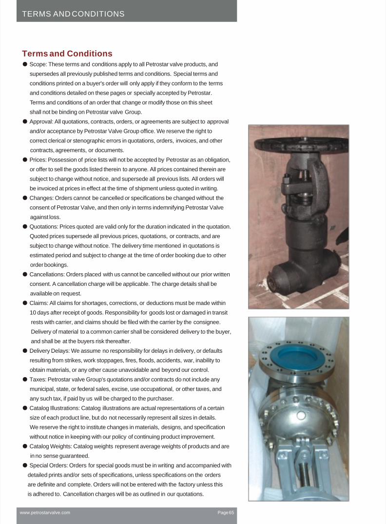
Scope: These terms and conditions apply to all Petrostar valve products, and
supersedes all previously published terms and conditions. Special terms and
conditions printed on a buyer's order will only apply if they conform to the terms
and conditions detailed on these pages or specially accepted by Petrostar.
Terms and conditions of an order that change or modify those on this sheet
shall not be binding on Petrostar valve Group.
Approval: All quotations, contracts, orders, or agreements are subject to approval
and/or acceptance by Petrostar Valve Group office. We reserve the right to
correct clerical or stenographic errors in quotations, orders, invoices, and other
contracts, agreements, or documents.
Prices: Possession of price lists will not be accepted by Petrostar as an obligation,
or offer to sell the goods listed therein to anyone. All prices contained therein are
subject to change without notice, and supersede all previous lists. All orders will
be invoiced at prices in effect at the time of shipment unless quoted in writing.
Changes: Orders cannot be cancelled or specifications be changed without the
consent of Petrostar Valve, and then only in terms indemnifying Petrostar Valve
against loss.
Quotations: Prices quoted are valid only for the duration indicated in the quotation.
Quoted prices supersede all previous prices, quotations, or contracts, and are
subject to change without notice. The delivery time mentioned in quotations is
estimated period and subject to change at the time of order booking due to other
order bookings.
Cancellations: Orders placed with us cannot be cancelled without our prior written
consent. A cancellation charge will be applicable. The charge details shall be
available on request.
Claims: All claims for shortages, corrections, or deductions must be made within
10 days after receipt of goods. Responsibility for goods lost or damaged in transit
rests with carrier, and claims should be filed with the carrier by the consignee.
Delivery of material to a common carrier shall be considered delivery to the buyer,
and shall be at the buyers risk thereafter.
Delivery Delays: We assume no responsibility for delays in delivery, or defaults
resulting from strikes, work stoppages, fires, floods, accidents, war, inability to
obtain materials, or any other cause unavoidable and beyond our control.
Taxes: Petrostar valve Group's quotations and/or contracts do not include any
municipal, state, or federal sales, excise, use occupational, or other taxes, and
any such tax, if paid by us will be charged to the purchaser.
Catalog Illustrations: Catalog illustrations are actual representations of a certain
size of each product line, but do not necessarily represent all sizes in details.
We reserve the right to institute changes in materials, designs, and specification
without notice in keeping with our policy of continuing product improvement.
Catalog Weights: Catalog weights represent average weights of products and are
in no sense guaranteed.
Special Orders: Orders for special goods must be in writing and accompanied with
detailed prints and/or sets of specifications, unless specifications on the orders
are definite and complete. Orders will not be entered with the factory unless this
is adhered to. Cancellation charges will be as outlined in our quotations.
www.petrostarvalve.com Page 65
TERMS AND CONDITIONS
Terms and Conditions

www.petrostarvalve.com Page 66
TERMS AND CONDITIONS
A. Material must be:
1. Of Petrostar Valve manufacture.
2. In clean, new and saleable condition. It must have been stored inside with proper
protection from open weather and corrosive atmosphere and dust.
3. Shipped from one of our service centers within the 12 calendar months preceding
the request for return, and the return will not cause inventory to exceed maximum
allowable levels.
4. Personally inspected by a Petrostar valve's representative authorized in written by
Petrostar valve Group office prior to its return.
5. Special or non-standard items are non-returnable.
6) The customer/ user shall send a written confirmation addressed to Petrostar valve
group in their letter head with the signature of authorized signatory stating that
The product was not damaged by buyer or their client .
7) All the freight and handling charges shall be on Customer's account.
B. A Return Goods Card must be furnished by a Petrostar Valve's representative after
inspection of the material, and must be returned with the shipment.
C. Shipments received without a Return Goods Authorization Card will be refused.
Customer will be responsible for any storage.
D. Material returned which is not of Petrostar's manufacture, not in clean and saleable
condition, or not authorized for return will be returned to the customer freight collect.
GOODS RETURN POLICY
This policy supersedes all other policies for return goods.
I. GOODS RETURNED AT CUSTOMER'S REQUEST:
A. Material must be in a clean & new condition.
B. The customer/ user shall send a written confirmation addressed to Petrostar valve
group in their letter head with the signature of authorized signatory stating that
The product was not damaged by buyer or their client
C. Return shipment should be made freight collect.
D. Full credit will be allowed as soon as the material is received and inspected by
Petrostar valve Office.
E. Customer must receive Return Goods authorization prior to the return of the
material. Return Goods Authorization Card must accompany shipment. Shipments
received without Return Goods Authorization Card will be refused. Return Goods
Authorization Card should be attached to the packing list. All requests to return
material to Petrostar valve must be submitted in writing to our General/Sales/
Operations Manager for authorization.
II. GOODS RETURNED BECAUSE OF ANY WRONG SUPPLY OR QUALITY RELATED PROBLEMS.
Petrostar Valve Group warrants each
product it manufactures, against defects
in material and workmanship under normal
use and service for a period of one year
after date of shipment.
This warranty is made to the buyer, and
does not extend to any other party unless
the end user name is advised to Petrostar
Valve Group at the time of order confirmation.
The obligation of Petrostar Valve
International under this warranty is limited to:
(a) replacement of any part or parts proven
defective in material or workmanship .
(b) repair of the product in the factory or
service center.
(c) refund of the purchase price.
This warranty does not extend to any claims
for labor, consequential damages, down
time, or any other loss, damage, or
expense of any kind arising out of the
defect. We do not allow claims for
unauthorized repairs, labor, or material.
We arenot responsible for loss of use,
personal injury, lost profits, or any other
damages whatsoever in connection with
the warranties set forth.
No warranty shall apply to any product
which has been modified or changed in
design or function after leaving Petrostar's
facilities or which is misused or operated
beyond its design capabilities, or used for
other than its intended purpose.
The buyer assumes all risk of this selection
of proper materials according to the
process and Petrostar assumes no
responsibility of incompatibility of materials
to the process medium.
The buyer shall permit Petrostar valve or its
authorized representative to inspect the
product so that it may determine its
obligation. Petrostar valve shall be entitled
to the return of the defective product or
parts. Buyer must notify Petrostar valve
promptly upon discover of any claimed
defect.
No material may be returned without first
obtaining written permission from Petrostar
Valve International/ Group. The foregoing
is the only warranty and no other is
expressed or implied.
WARRANTY
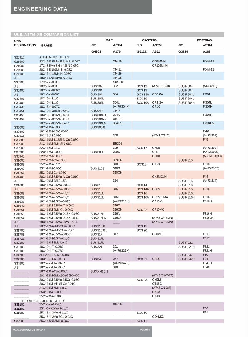
www.petrostarvalve.com Page 67
UNS/ ASTM-JIS COMPARISON LIST
UNS
DESIGNATION GRADE
S20910
S21800
S21904
S24000
S24100
JIS
S30200
JIS
S30400
JIS
S30403
S30409
S30430
S30451
S30452
S30453
___
S30600
S30800
S30815
S30880
S30900
S30908
S30909
S30940
S31000
S31008
S31040
S31254
S31400
JIS
S31600
JIS
S31603
S31609
S31635
S31640
S31651
S31653
S31654
JIS
JIS
S31700
S31703
S31725
S32100
S32109
S33100
S34700
S34709
S34800
JIS
_________
_________
_________
_________
_________
_________
_________
_________
S31100
S31200
S31803
S32900
BAR CASTING FORGING
JIS
G4303
ASTM
A276
JIS
G5121
ASTM
A351
JIS
G3214
ASTM
A182
AUSTENITIC STEELS
22Cr-12Ni5Mn-2Mo-V-N-0.04C
17Cr-8.5Mo-8Mn-4Si-N-0.08C
20Cr-6.5Ni-9Mn-N-0.08C
18Cr-3Ni-13Mn-N-0.06C
18Cr-1.5Ni-13Mn-N-0.1C
17Cr-7Ni-0.1C
18Cr-8Ni-0.1C
18Cr-8Ni-0.06C
18Cr-8Ni-0.06C
18Cr-9Ni-Lo,C
18Cr-9Ni-Lo,C
18Cr-8Ni-0.07C
18Cr-9Ni-3.5Cu-0.06C
18Cr-8Ni-0.15N-0.06C
18Cr-8Ni-0.25N-0.06C
18Cr-9Ni-0.15N-0Lo,C
18Cr-13Ni-0.06C
18Cr-15Ni-4Si-0.009C
20Cr-11Ni-0.06C
20Cr-10Ni-1.15Si-N-Ce-0.08C
21Cr-10Ni-2Mn-Si-0.06C
22Cr-12Ni-0.1C
22Cr-12Ni-0.06C
22Cr-12NI-0.07C
22Cr-12NI-Cb-0.06C
25Cr-20Ni-0.1C
25Cr-20Ni-0.06C
25Cr-20Ni-Cb-0.06C
20Cr-18Ni-6.5Mo-N-Cu-0.01C
25Cr-20Ni-2Si-0.15C
18Cr-12Ni-2.5Mo-0.06C
18Cr-12Ni-2.5Mo-0.06C
18Cr-12Ni-2.5Mo-Lo,C
18Cr-12Ni-2.5Mo-Lo,C
18Cr-12Ni-2.5Mo-0.07C
18Cr-12Ni-2.5Mo-Ti-0.06C
18Cr-13Ni-2Mo-Cb-0.06C
18Cr-12Ni-2.5Mo-0.15N-0.06C
18Cr-12Ni-2.5Mo-0.15N-Lo, C
18Cr-12Ni-2.5Mo-0.2N-Lo, C
18Cr-12Ni-2Mo-2Cu-0.06C
18Cr-12Ni-2Mo-2Cu-Lo, C
18Cr-12Ni-3.5Mo-0.06C
18Cr-12Ni-3.5Mo-Lo, C
18Cr-16Ni-5Mo-Lo, C
18Cr-9Ni-Ti-0.06C
18Cr-9Ni-Ti-0.07C
8Cr-20Ni-1Si-Mn-0.15C
18Cr-9Ni-Cb-0.06C
18Cr-9Ni-Cb-0.07C
18Cr-9Ni-Cb-0.06C
18Cr-13Ni-4Si-0.06C
20Cr-24Ni-3Mo-2Cu-3Si-0.05C
20Cr-29Ni-2.5Mo-3.5Cu-0.05C
20Cr-33Ni-Min-Si-Cb-0.01C
21Cr-24Ni-5Mo-Lo, C
25Cr-20Ni--0.03C
25Cr-20Ni--0.04C
25Cr-6Ni--0.04C
25Cr-6Ni-2Mo-N-Lo,C
25Cr-6Ni-3Mo-N-Lo,C
25Cr-5Ni-2Mo-3Cu-0.02C
25Cr-4.5Ni-2Mo-0.06C
FERRITIC-AUSTENTIC STEELS
SUS 302
SUS 304
SUS 304
SUS 304L
SUS 304L
SUSXM7
SUS 304N1
SUS 304N2
SUS 304LN
SUS 305J1
SUS 309S
SUS 310S
SUS 316
SUS 316
SUS 316L
SUS 316L
SUS 316N
SUS 316LN
SUS 316J1
SUS 316J1L
SUS 317
SUS 317L
SUS 317L
SUS 321
SUS 347
SUS XM15J1
XM-19
____
XM-11
XM-29
XM-28
SUS 301
302
304
304L
(A479 304H)
XM-7
304N
XM-21
304LN
308
______
ER308
309
309S
309Cb
310
310S
310Cb
____
314
316
316L
(A479 316H)
316Ti
316Cb
316N
316LN
____
317
___
321
(A479 321H)
347
(A479 347H)
318
XM-26
______
SCS 12
SCS 13
SCS 13A
SCS 19
SCS 19A
SCS 17
SCS18
SCS 14
SCS 14A
SCS 16
SCS 16A
SCS 22
BCS 15
BCS 20
SCS 21
SCS 23
SCS 10
SCS 11
CG6MMN
CF102MnN
(A743 CF-20)
CF8, 8A
CF3, 3A
CF 10
(A743 CG12)
CH20
CH8
CH10
CK20
CK3MCuN
CF8M
CF3M, 3MA
CF10M
CF10MC
(A743 CF-3MN)
(A743 CF-3MN)
CGBM
CFBC
(A743 CN-7MS)
CN7M
CT15C
(A743 CN-3M)
HK30
HK40
CD4MCu
SUS F 304
SUS F 304
SUS F 304L
SUS F 304L
SUS F 304H
SUS F 310
SUS F 316
SUS F 316
SUS F 316L
SUS F 316L
SUS F 316H
SUS F 321
SUS F 321H
SUS F 347
SUS F 347H
F XM-19
F XM-11
(A473 302)
F 304
F 304L
F 304H
F 304N
F 304LN
F 46
(A473 308)
F45
(A473 309)
(A473 309S)
(A336 F 309H)
F310
(A473 310S)
F44
(A473 314)
F316
F316L
F316H
F316N
F316LN
F317
F317L
F321
F321H
F10
F347
F347H
F348
F50
F51
ENGINEERING DATA

www.petrostarvalve.com Page 68
GRADE BAR CASTING FORGINGTYPE OF STEEL
Carpenter 20
Alloy 20 Cb-3
CN7M, SCS 23
CN-7MS
Carpenter 20 Mod
Alloy 20 Mod
CN-3M
Nickel
Alloy 200
Alloy 201
CZ-100
Duranickel 301
Monel
Alloy 400
Alloy 405
M-35-1
M-35-2
N-30H
M-25S
M-30C
Inconel
Alloy 600
CY 40
Alloy 625
CW-6MC
Inconel 601
Inconel 609
Inconel X-750
Inconel 751
CY5SnBiM
Incoloy
Alloy 800
Alloy 800H
Alloy 825
Hastelloy B
Alloy B
A-12MV
Alloy B-2
N-7M
Hastelloy C
Alloy C-276
CW-12MW
Alloy C-4
CW-2M
Alloy C-22
CW-6M
Hastelloy G
Alloy G
Alloy G-2
Alloy G-30
Alloy G-3
Hastelloy N
Alloy N
Hastelloy X
Alloy X
Js 700
Alloy 700
CN-3M
904L
Alloy 904L
RA-330
Alloy 330
Nimonic 80A
Nimonic 80A
IN-102
IN-102
Affcorr
Affcorr
Cr-Ni-Fe-Mo-Cu-Cb
35Ni-20Cr-2.5Mo-39Fe-35Cu-Cb-0.05C
29Ni-20Cr-2.5Mo-45Fe-35Cu-0.05C
24Ni-19Cr-2.5Mo-49Fe-2Cu-3Si-0.05C
Ni-Fe-Cr-Mo
26Ni-22Cr-5Mo-47Fe-Ti-0.03C
25Ni-21Cr-5Mo-49Fe-Lo, C
Ni
99Ni-0.1C
99Ni-0.01C
97Ni-0.8C
95Ni-4.5A1-Ti-0.2C
Ni-Cu
69Ni-31Cu-0.2C(Si<0.5) (S<0.024)
69Ni-31Cu-0.2C(Si<0.5) (S:0025 - 0.06)
70Ni-30Cu-0.25C(Si<1.25)
70Ni-30Cu-0.25C(Si<2.00)
67Ni-31Cu-3Si-0.2C
66Ni-30Cu-4Si-0.15C
66Ni-30Cu-1.5Si-2Cb-0.2C
Ni-Cr-Fe(Ni-Cr-Mo-Cb)
77Ni-15Cr-8Fe-0.1C
77Ni-15Cr-(8Fe)-0.3C
65Ni-22Cr-9Mo-4Cb-0.08C
65Ni-22Cr-9Mo-4Cb-0.04C
61Ni-23Cr-14Mo-1.5A1-0.08C
62Ni-23Cr-9Fe-0.03C
73Ni-16Cr-7Fe-1Cb-2.5Ti-A1-0.06C
73Ni-16Cr-7Fe-1Ni-2.5Ti-A1-0.08C
76Ni-13Cr-3Mo-4Bi-4Sn-0.03C
Ni-Fe-Cr(Ni-Fe-Cr-Mo-Cu)
33Ni-21Cr-46Fe-A1-Ti-0.08C
33Ni-21Cr-46Fe-A1-Ti-0.075C
42Ni-22Cr-3Mo-30Fe-2Cu-1Ti-0.03C
Ni-Mo
67Ni-28Mo-5Fe-V-0.03C
67Ni-28Mo-5Fe-V-0.1C
72Ni-28Mo-0.01C
68Ni-32Mo-0.05C
Ni-Mo-Cr
58Ni-16Cr-16Mo-6Fe-4W-0.005C
58Ni-16Cr-16Mo-6Fe-4W-0.01C
68Ni-16Cr-16Mo-0.008C
68Ni-16Cr-16Mo-0.01C
58Ni-21Cr-14Mo-4Fe-3W-0.008C
62Ni-19Cr-19Mo-0.05C
Ni-Cr-Fe-Mo-Cu
46Ni-22Cr-6.5Mo-20Fe-5Mn-2Cu-0.03C
50Ni-25Cr-6Mo-17Fe-1Cu-1Ti-Lo, C
44Ni-30Cr-5Mo-15Fe-2Cu-1Cb-3W-Lo, C
49Ni-22Cr-7Mo-20Fe-2Cu-0.08C
Ni-Mo-Cr-Fe
76Ni-7Cr-17Mo-0.06C
Ni-Cr-Mo-Fe
48Ni-22Cr-9Mo-19Fe-1.5Co-W-0.1C
Ni-Fe-Cr-9Mo-Cb
25Ni-21Cr-4.5Mo-49Fe-Cb-0.02C
25Ni-21Cr-5Mo-49Fe-Lo, C
Ni-Fe-Cr-9Mo-Cb
26Ni-21Cr-4.5Mo-47Fe-1.5Cu-0.01C
Ni-Fe-Cr-Si
36Ni-19Cr-44Mo-1Si-0.06C
Ni-Cr
76Ni-20Cr-2Ti-1.5A1-0.08C
Ni-Cr-Fe-Cb-Mo-W
Ni-Cr-Mo-W
55Ni-31Cr-10.5Mo-2.5W-Cb-0.1C
JIS ASTM ASTM ASTM
H 4562 NNCB
H 4562 NNCB
H 4562 NDB
H 4553 NCuB
G 4901 NCF 600
G 4901 NCF 601
B 166 NO6690
G 4901 NCF 750
G 4901 NCF 751
G 4901 NCF 800
G 4901 NCF 800H
G 4901 NCF 825
G 4901 NCF 80A
B473 NO8020
B621 NO8320
B160 NO2200
B160 NO2201
B164 NO4400
B164 NO4405
B 166 NO6600
B 446 NO6625
B 637 NO7750
B 408 NO8800
B 406 NO8810
B 425 NO8825
B 335 N10001
B 335 N10665
B 574 N10276
B 574 NO6455
B 574 NO6022
B 581 NO6007
B 581 NO6975
B 581 NO6030
B 581 NO6985
B 573 N10003
B 572 NO6002
B 581 NO 7008
B 649 NO8904
B 511NO8330
B 637 NO7080
B518 NO6102
B 756 NO6110
B462 NO8020
B621 NO8320
B160 NO2200
B160 NO2201
B164 NO4400
B164 NO4405
B 564 NO6600
B 564 NO6625
B 637 NO7750
B 564 NO8800
B 564 NO8810
B 425 NO8825
B 335 N10001
B 335 N10665
B 335 N10276
B 574 NO6455
B 574 NO6022
B 581 NO6007
B 581 NO6975
B 581 NO6030
B 581 NO6985
B 573 N10003
B 572 NO6002
B 672 NO8700
B 649 NO8904
B 511NO8330
B 637 NO7080
B 564 NO6110
66Ni-15Cr-3Mo-7Fe-3Cb-3W-A1-Ti-MgB-Zr-0.06C
A 351 CN7N
A 743 CM-7MS
A 743 CM-3M
A 494 CZ-100
A 494 M-351
A 494 M-35-2
A 494 M-30H
A 494 M-25S
A 494 M-30C
A 494 CY-40
A 494 CW-6MC
A 494 CY5SnSim
A 494 N-12MV
A 494 N-7M
A 494 CW-12MW
A 494 CW-12M
A 494 CW-6M
A 743 CN-3M
SPECIAL ALLOY STEEL
ENGINEERING DATA

www.petrostarvalve.com Page 69
PETROSTAR VALVE ORDER CODES WITH COMENTS
ORDER CODING.
TYPE CLASS CONNECTION DESIGN
Floater, Reduced Bore, Unibody, Side entry
2Pc, Floater side entry BV, Full Bore, Bolted body
2Pc, Floater side entry BV, Reduced Bore, Bolted Body
3Pc, Floater Side entry BV, Full Bore, Bolted Body
3Pc, Floater Side entry BV, RB, Bolted Body
2PcTrunnion, FB, Side entry, Bolted Body, DB&B
2PcTrunnion, RB, Side entry, Bolted Body, DB&B
3PcTrunnion, FB, Side entry, Bolted Body,DB&B
3pcTrunnion, RB, Side entry, Bolted body, DB&B
Top entry BV, FB, Bolted body, Bolted Body, DB&B
Top entry BV, RB, Bolted Body, Bolted Body, DB&B
Welded BV, FB, DB&B, Sealant Injection, Trunnion
Welded BV, RB, DB&B, Sealant Injection, Trunnion
Gate,B. Bonnet, OS&Y, BG, Rising stem, Non rising HW
Gate,W. Bonnet, OS&Y, BG, Rising stem, Non rising HW
Gate, P. Seal, OS&Y, BG, Rising stem, Non rising HW
Globe,B. Bonnet, OS&Y, BG, Rising stem & HW
Globe,W. Bonnet, OS&Y, BG, Rising stem & HW
Globe, P. Seal, OS&Y, BG, Rising stem & HW
Swing Check, B. Cover
Swing Check, W. Cover
Swing Check, P. Seal
Dual Plate Check, Integral seat, Spring loaded
Piston Check Valve, integral seat, spring loaded
Ball Check Valve, integral seat, spring loaded
Resiliant Butterfly, concentric design
Double offset Butterfly, Bolted gland
Triple Offset Butterfly, Bolted gland
T C Gate Valve, BB, OS&Y, BG, Rising stem, NR HW
Needle Valve, Bar stock design, T handle
Special Valve
Special feature
1
3
6
8
9
15
25
K1
K2
K3
10
16
20
25
40
Class150
Class 300
Class 600
Class 800
Class 900
Class 1500
Class 2500
1000WOG
2000WOG
3000WOG
PN10
PN16
PN20
PN25
PN40
R
F
J
S
B
N
O
D
L
W
X
RF
FF
RTJ
SW
BW
NPT
NPT/SW
D Flanged
Lug Type
Wafer
Other
All Flanged Ball valves shall be NACE and Fire safe
All flanged Ball valves are with Locking facility
Trunnion ball valves are with sealant injection facility
All Trunnion ball valves are with spring assisted seats
All Ball valves are with anti-blow out stem
2" and above ball valves are with Bolted gland.
Standard forged steel GGC valves are with integral seat
API 602 forged Gate valves are with Solid wedge.
2" and above size Gate valves are with Tappered H wedges
Body joint gasket for 300 # and above valves are metallic
Metal seated butterfly valves are with Tripple Offset design
Class 300 and 600 butterfly valves are HP type.
Class 2500 GGC Valves are Pressure seal bonnet type
1)
2)
3)
4)
5)
6)
7)
8)
9)
10)
11)
12)
13)
GENERAL SPECS:-
A
B
C
D
E
F
G
H
J
K
L
M
N
GB
GW
GP
LB
LW
LP
CB
CW
CP
DP
PV
BV
RB
HB
TB
TG
HW
S
-s
1
2
3
4
Firesafe NACE
Firesafe
NACE
Standard

BODY OPERATORSEAT&SEAL(BV & BLY)STEMTRIM
www.petrostarvalve.com Page 70
PETROSTAR VALVE ORDER CODES WITH COMENTS
ORDER CODING.
A
B
C
D
E
F
G
H
I
J
K
L
M
N
O
P
Q
R
S
T
U
V
W
Y
Z
Aa
Ab
Ac
Ba
Bb
Bc
Ca
Cb
Cc
X
-e
WCB
A105
LCC
LF2
LCB
CF8
F304
CF3
F304L
CF8M
F316
CF3M
F316L
A890-4A
F51
A890-5A
F53
A890-6A
F55
Ductile Iron
A126
CN7M
WCC
CF8C
CG8M
C5
C12
C12A
WC1
WC6
WC9
LC1
LC2
LC3
Special
ENP coated
1
2
2h
2s
5
8
9
10
10h
11
12
13
14
15
15h
15s
16
16h
16s
17
17h
17s
19
19h
19s
20
20h
20s
A
B
C
D
E
F
G
H
X
(e)
13% Cr
SS304
304SS+F STL
304SS+1/2 STL
13%Cr+ F STL
13%Cr+ F STL
Monel
SS316
SS316+F STL
Monel+1/2 STL
SS316+1/2 STL
Alloy 20
Alloy 20+1/2 STL
SS304L
SS304L +F STL
SS304L +1/2 STL
SS316L
SS316L+F STL
SS316L+1/2 STL
SS347
SS347+F STL
SS347+1/2 STL
Hastelloy
Hastelloy+F STL
Hastelloy+1/2 STL
Inconel
Inconel+F. STL
Inconel+1/2 STL
A105+ENP
WCB+ENP
WC9+ENP
CF8
CF8M
A536
B148
CA15+SS410
Special
ENP Coating
a
b
c
d
f
g
h
i
j
k
l
m
n
o
p
q
r
s
x
-e
F6a
SS 304
SS 304L
SS 316
SS 316L
SS 410
SS 416
SS 630
SS 431
4140
17-4 PH
Monel
F51
F53
F55
Alloy 20
Hastelloy
Inconel
Special
ENP Coating
R
Ny
D
P
C
M
K
E
B
V
N
T
S
(O)
RTFE+Viton/Grap
Nylon+Viton/Grap
Derlin+Viton/Grap
PEEK+Viton/Grap
C.Graph+Viton/Grap
Metal+Viton/Grap
RTFE+PTFE
EPDM
Buna-N
Viton
Neoprene
PTFE
Stellited
Special/Other
1)
2)
3)
4)
1) Stem material shall be same material as Trim unless specifically
requested otherwise. (e.g Trim 12 valve will have SS 316 stem.)
2) Wedge or disc shall be same or superior material as body and trim
material will be overlaid
3) ENP Coating shall be minimum 75 Micron thick
Stelliting on 1/2 stellited valves are always on body seat by default
TRIM DATA :-
L
G
P
H
E
W
O
Lever Operator
Gear Operator
Pneumatic Actuator
Hydraulic Actuator
Electrical actuator
Wheel Operated
Gas Over Oil

www.petrostarvalve.com Page 71
VALVE PHOTOS
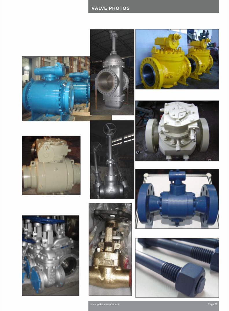
www.petrostarvalve.com Page 72
VALVE PHOTOS

USA
1200, Smith Street
1600, Houston, Tx
Tel (713) 3533917
Fax(713) 3534601
e-mail [email protected]
www.petrostarvalve.com
Middle East
D-4, SAIF Zone
Sharjah, UAE
Tel (971) 6 5571740
Fax(971) 6 5571750
e-mail [email protected]
PETROSTAR VALVE - ROK
162-1, Yuhari, Jang Yu-meyon
Gimhae City, Gyeongnam
Republic Of Korea.
As we continuously end eavor to improve our products, the data given herein are subject to change without notice.