assisted-balance bicycle senior design fall 2010 cycle …
TRANSCRIPT
ASSISTED-BALANCE BICYCLE
SENIOR DESIGN
FALL 2010
CYCLE 1 REPORT
Daniel Dunbar, Daniel Golden, Mason Nixon, Brett Smith,
and Bryan Wall
2
Table of Contents
I. Introduction 3
II. Bicycle Physics and Equipment Placement………………..Bryan Wall 5
III. Motor and Power Systems………………………………………..Brett Smith 7
IV. Structural Design/Accelerometer……………………………..Mason Nixon 10
V. Balancing Control System Theory……………………………..Daniel Dunbar 15
VI. Embedded System Architecture………………………………..Daniel Golden 20
VII. Conclusion 23
3
I. Introduction
The most difficult part of learning to ride a bicycle for many people is creating enough
momentum through pedaling in order to allow the bike to stabilize itself. Once a rider learns
how to mount a bicycle and distribute his or her weight, the rest is up to the natural physics of
the wheels, seat, pedals, brakes and handlebars. Imagine if this most difficult task was eased by
taking away the necessity of stabilizing oneself when learning to ride a bike by adding a device
that helped the rider balance.
When an individual is first learning to ride a bicycle there is typically a device in place to
help them called training wheels. The purpose of training wheels is to prevent the person
learning to ride the bike from falling over if that person becomes unbalanced. Training wheels
do not however teach a new rider how to balance since there is not generally even the
capability of trying to balance when the two wheeled device is made into a stable four wheel
device. This means that when the training wheels are removed after the rider learns about
peddling and steering, that rider is suddenly introduced to an aspect of riding a bicycle that he
or she has not had to deal with before; balancing. Our balance-assist can create the
intermediary step and allow the rider to become more confident in their ability to control the
bike and ultimately learn to ride the bike with no assist.
Before a device can be made to help assist with the balancing of a rider, an
understanding of the physics of a bicycle, specifically the bike falling, is required. When a bike is
falling out of balance, it is as if the bicycle is making a circle to the side of the fall, pulling the

4
bike towards the center of that circle, sometimes referred to as the "circle of fall." In order to
keep from falling into the circle of fall, otherwise known as crashing, the rider has to create a
counter-pull out of the fall. There are two ways a rider can create this counter-pull to overcome
the fall. One choice is to quickly speed up the bicycle. The other is to quickly tighten the radius
of the circle of fall by turning the front tire into the direction of fall. Experienced riders
instinctively do both as required. What we propose to do is create the counter-pull necessary to
allow for the rider to remain upright by using a third method.
Beyond teaching someone how to ride a bicycle, the balance assist also has application
in rehabilitation of people with inner ear problems, which can cause a deficiency in the ability
to self-balance, or other debilitating injuries and also in aiding the elderly who have lost their
confidence in their ability to self-balance.
As a senior design project, this project encompasses many areas of engineering. General
dynamic physics is involved in determining the motion of a bicycle. The problem of balancing a
bicycle is directly comparable to the classic nonlinear control systems problem of the inverted
pendulum. There is a great mechanical aspect of this problem in devising mounting methods
and mass distribution of our balance assist. Lastly, there is a project management aspect of the
project that involves time-management, money-management, and teamwork that are all well
accounted for by our proposal.

5
II. Bicycle Physics and Equipment Placement Bryan Wall
The primary principal that allows a falling object, such as a bicycle, to
have its position and angular acceleration changed by an accelerating
flywheel is something that is called “coupled forces”. This essentially means
that as long as the flywheel is fixed to the bicycle, the moment, also called
torque, which is generated by the angularly accelerating flywheel, is
transferred to the angular acceleration of the bicycle which is then used to
rotate the bicycle back to the vertical position. There are many variables
that must be calculated to determine what angular acceleration of the flywheel is need to
counteract the falling motion of the bike due to gravity including the torque created by the
bicycle falling as well as the moment of inertia of the flywheel.
To calculate the torque of the bicycle falling we must first calculate the center of gravity,
also known as center of mass, of the bicycle. The reason for this is because the force of the
gravity pulling the bicycle down can be represented by a single force that is applied to the
object at its center of mass. This is not so simple a task when trying to calculate the center of
mass for an oddly shaped object such as a bicycle. However, we can easily calculate the center
of mass of simple geometric shapes such as discs and rods. This is helpful due to the fact that a
bicycle is essentially made up of two discs and a few rods. Therefore, the process to find the
center of mass for a bicycle becomes fairly simple. All that has to be done is to find the center
of mass of all the individual pieces of the bicycle. Then, those individual centers of masses can
6
be added up using weighted averages to find the center of mass of the entire bicycle. Once that
is done, the radial arm from the ground to the center of mass where the gravity acts on is
known, and the torque of the falling bicycle can be calculated.
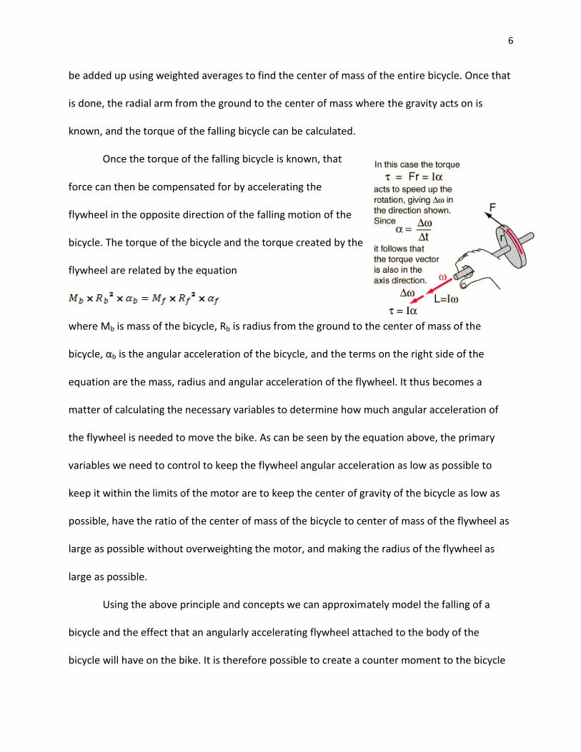
Once the torque of the falling bicycle is known, that
force can then be compensated for by accelerating the
flywheel in the opposite direction of the falling motion of the
bicycle. The torque of the bicycle and the torque created by the
flywheel are related by the equation
where Mb is mass of the bicycle, Rb is radius from the ground to the center of mass of the
bicycle, αb is the angular acceleration of the bicycle, and the terms on the right side of the
equation are the mass, radius and angular acceleration of the flywheel. It thus becomes a
matter of calculating the necessary variables to determine how much angular acceleration of
the flywheel is needed to move the bike. As can be seen by the equation above, the primary
variables we need to control to keep the flywheel angular acceleration as low as possible to
keep it within the limits of the motor are to keep the center of gravity of the bicycle as low as
possible, have the ratio of the center of mass of the bicycle to center of mass of the flywheel as
large as possible without overweighting the motor, and making the radius of the flywheel as
large as possible.
Using the above principle and concepts we can approximately model the falling of a
bicycle and the effect that an angularly accelerating flywheel attached to the body of the
bicycle will have on the bike. It is therefore possible to create a counter moment to the bicycle
7
falling using a flywheel while keeping the values within the capabilities of the motor and the
stress limits of the materials for the flywheel.
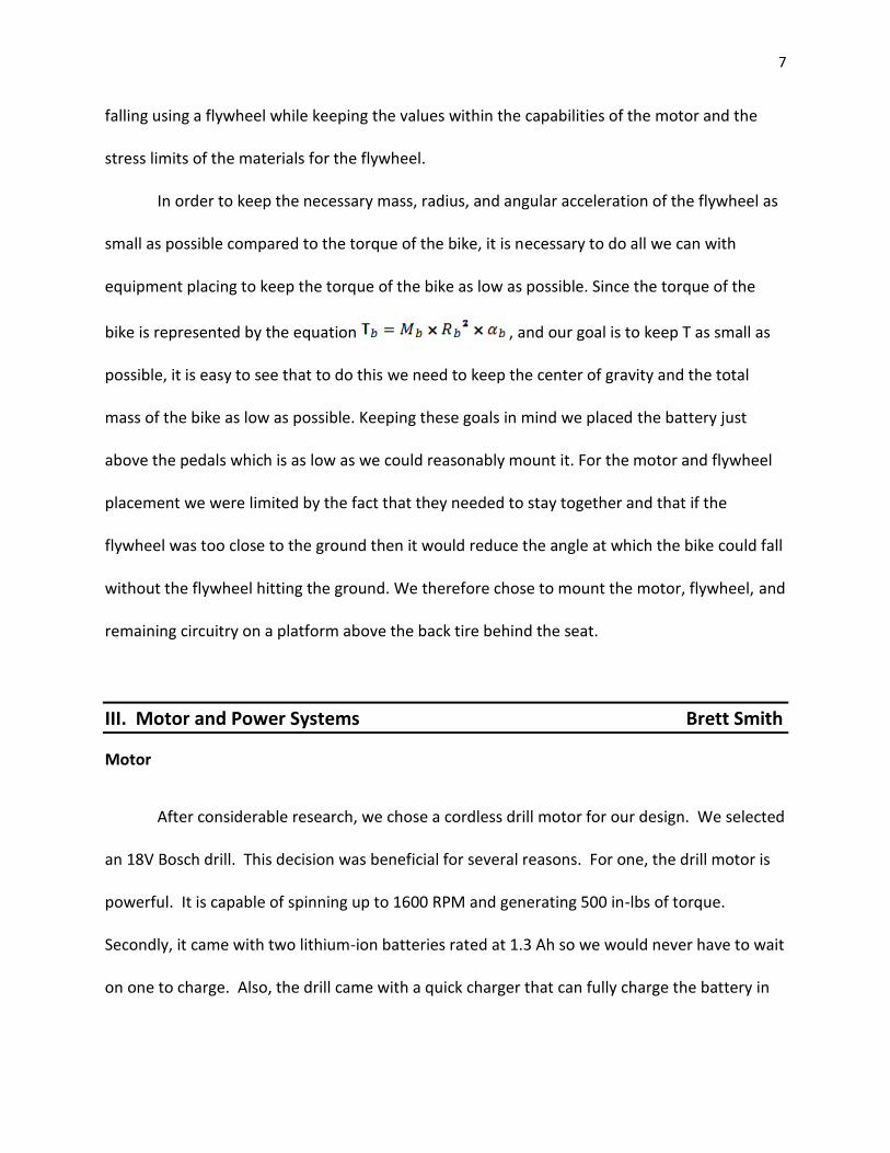
In order to keep the necessary mass, radius, and angular acceleration of the flywheel as
small as possible compared to the torque of the bike, it is necessary to do all we can with
equipment placing to keep the torque of the bike as low as possible. Since the torque of the
bike is represented by the equation , and our goal is to keep T as small as
possible, it is easy to see that to do this we need to keep the center of gravity and the total
mass of the bike as low as possible. Keeping these goals in mind we placed the battery just
above the pedals which is as low as we could reasonably mount it. For the motor and flywheel
placement we were limited by the fact that they needed to stay together and that if the
flywheel was too close to the ground then it would reduce the angle at which the bike could fall
without the flywheel hitting the ground. We therefore chose to mount the motor, flywheel, and
remaining circuitry on a platform above the back tire behind the seat.
III. Motor and Power Systems Brett Smith
Motor
After considerable research, we chose a cordless drill motor for our design. We selected
an 18V Bosch drill. This decision was beneficial for several reasons. For one, the drill motor is
powerful. It is capable of spinning up to 1600 RPM and generating 500 in-lbs of torque.
Secondly, it came with two lithium-ion batteries rated at 1.3 Ah so we would never have to wait
on one to charge. Also, the drill came with a quick charger that can fully charge the battery in
8
30 minutes. Lastly, the drill has forward and reverse functionality built into it (more on that
later).
Motor Controller
As mentioned earlier, the drill has forward and reverse functionality built into it.
However, after purchasing the drill, we discovered that it has a mechanical switch that allows
for the reverse to be activated. This is undesirable for a couple reasons. Mechanical switching
is much slower than electrical switching. Also, to be able to switch directions in software we
would have to have some sort of actuator to flip the switch which would just overcomplicate
the circuitry. We looked into designing an H-bridge circuit using transistors to allow reversing
the voltage applied to the motor on the fly. This would be a rather cheap and cost effective
method. The problem with this solution is that all the MOSFET transistors we saw had low
current ratings. Our drill has been measured at up to 12 amps. In the end, we settled on a
premade motor controller ordered off the internet. It is rated up to 15 amps (21 amps if a heat
sink is added). This saves us room since it is all contained on a printed circuit board. Plus, it is
very easy to interface with the microcontroller.
9
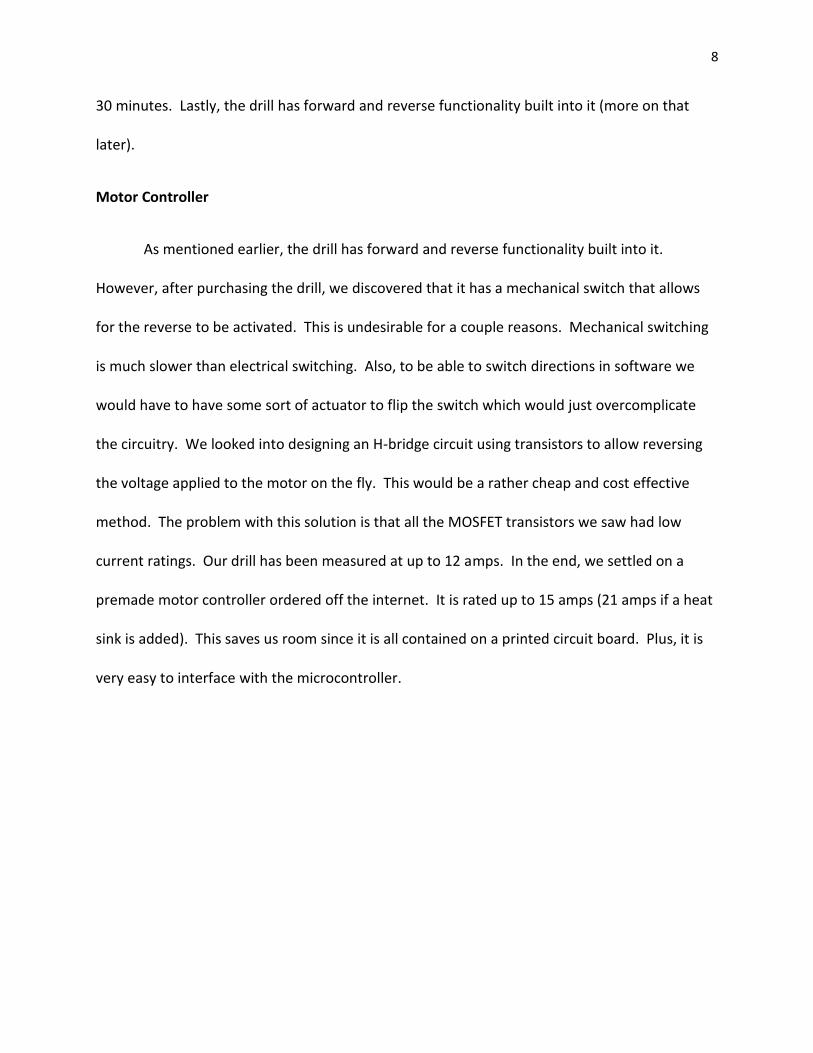
Figure 1 - Motor Controller Pinout
Wiring
As far as the wiring of everything, we have mounted most of the components on a
breadboard that sits on a metal mounting plate positioned behind the bike seat. This is the
best option for flexibility. The breadboard is attached to the plate by Velcro for easy removal.
The motor controller, accelerometer, and microcontroller are all wired together on this
breadboard. The 18V battery is mounted to a wooden shelf below the bike seat. We are also
using a 9V battery to power the microcontroller, motor controller, and accelerometer. This
battery is mounted beside the breadboard. Rather than, try to feed everything off the 18V
battery, we felt it best to use a smaller battery. This keeps the motor circuit somewhat isolated
from our other more sensitive devices. Since the motor does draw considerable current, we
had to use thicker wires than the 22 gauge used on the breadboard. The wires inside the drill
are 14 gauge. To be on the safe side we went ahead and wired the motor controller to the
battery and motor using 12 gauge.
10
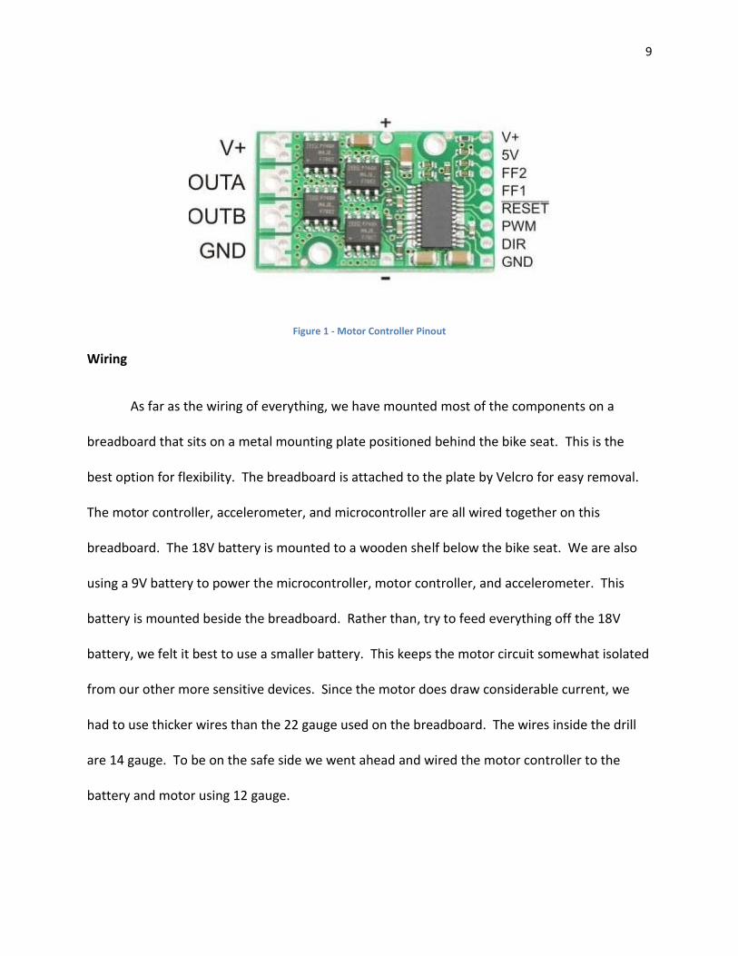
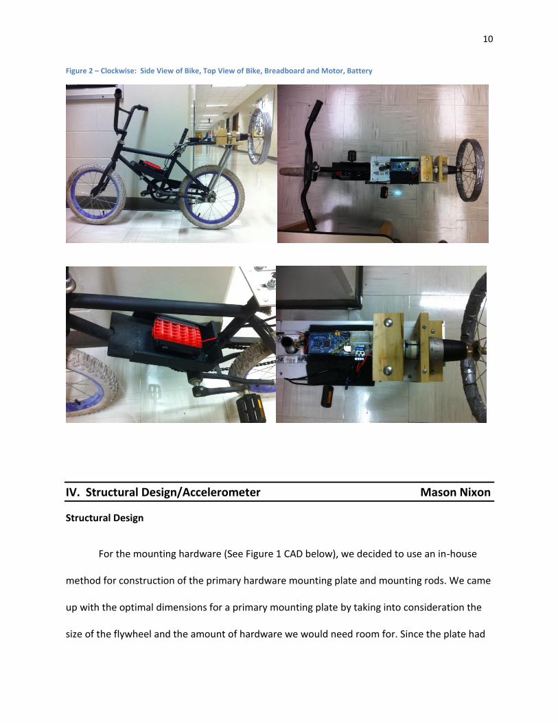
Figure 2 – Clockwise: Side View of Bike, Top View of Bike, Breadboard and Motor, Battery
IV. Structural Design/Accelerometer Mason Nixon
Structural Design
For the mounting hardware (See Figure 1 CAD below), we decided to use an in-house
method for construction of the primary hardware mounting plate and mounting rods. We came
up with the optimal dimensions for a primary mounting plate by taking into consideration the
size of the flywheel and the amount of hardware we would need room for. Since the plate had
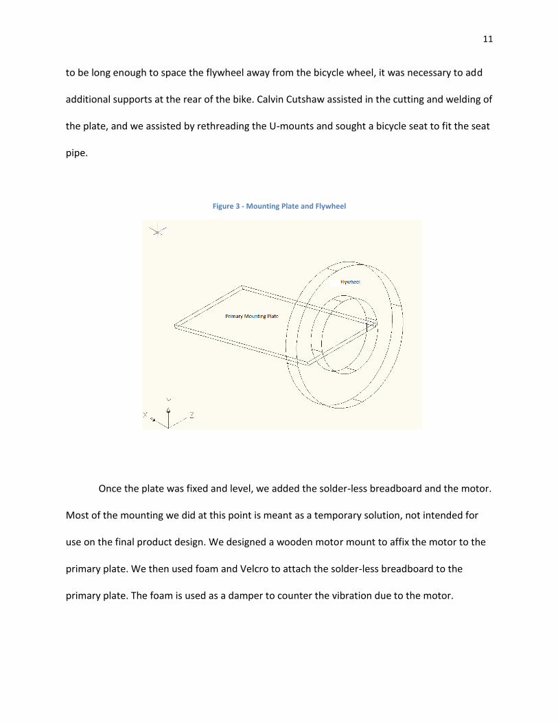
11
to be long enough to space the flywheel away from the bicycle wheel, it was necessary to add
additional supports at the rear of the bike. Calvin Cutshaw assisted in the cutting and welding of
the plate, and we assisted by rethreading the U-mounts and sought a bicycle seat to fit the seat
pipe.
Figure 3 - Mounting Plate and Flywheel
Once the plate was fixed and level, we added the solder-less breadboard and the motor.
Most of the mounting we did at this point is meant as a temporary solution, not intended for
use on the final product design. We designed a wooden motor mount to affix the motor to the
primary plate. We then used foam and Velcro to attach the solder-less breadboard to the
primary plate. The foam is used as a damper to counter the vibration due to the motor.
12
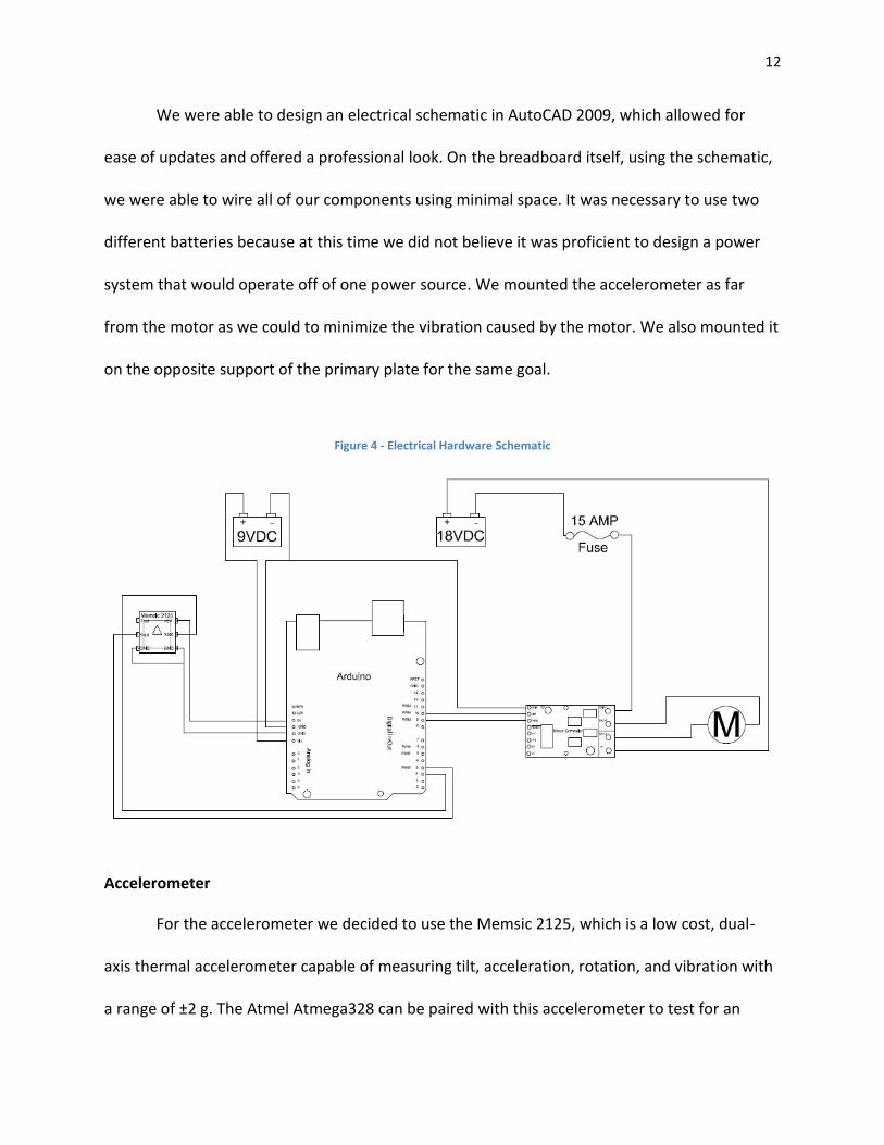
We were able to design an electrical schematic in AutoCAD 2009, which allowed for
ease of updates and offered a professional look. On the breadboard itself, using the schematic,
we were able to wire all of our components using minimal space. It was necessary to use two
different batteries because at this time we did not believe it was proficient to design a power
system that would operate off of one power source. We mounted the accelerometer as far
from the motor as we could to minimize the vibration caused by the motor. We also mounted it
on the opposite support of the primary plate for the same goal.
Figure 4 - Electrical Hardware Schematic
Accelerometer
For the accelerometer we decided to use the Memsic 2125, which is a low cost, dual-
axis thermal accelerometer capable of measuring tilt, acceleration, rotation, and vibration with
a range of ±2 g. The Atmel Atmega328 can be paired with this accelerometer to test for an
13
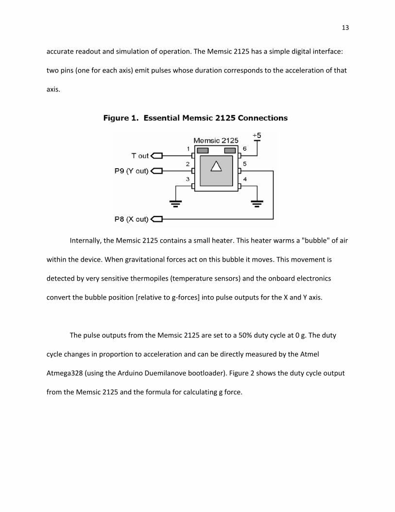
accurate readout and simulation of operation. The Memsic 2125 has a simple digital interface:
two pins (one for each axis) emit pulses whose duration corresponds to the acceleration of that
axis.
Internally, the Memsic 2125 contains a small heater. This heater warms a "bubble" of air
within the device. When gravitational forces act on this bubble it moves. This movement is
detected by very sensitive thermopiles (temperature sensors) and the onboard electronics
convert the bubble position [relative to g-forces] into pulse outputs for the X and Y axis.
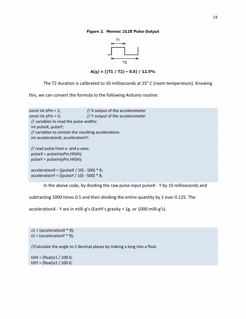
The pulse outputs from the Memsic 2125 are set to a 50% duty cycle at 0 g. The duty
cycle changes in proportion to acceleration and can be directly measured by the Atmel
Atmega328 (using the Arduino Duemilanove bootloader). Figure 2 shows the duty cycle output
from the Memsic 2125 and the formula for calculating g force.
14
The T2 duration is calibrated to 10 milliseconds at 25° C (room temperature). Knowing
this, we can convert the formula to the following Arduino routine:
const int xPin = 2; // X output of the accelerometer const int yPin = 3; // Y output of the accelerometer // variables to read the pulse widths: int pulseX, pulseY; // variables to contain the resulting accelerations int accelerationX, accelerationY; // read pulse from x- and y-axes: pulseX = pulseIn(xPin,HIGH); pulseY = pulseIn(yPin,HIGH); accelerationX = ((pulseX / 10) - 500) * 8; accelerationY = ((pulseY / 10) - 500) * 8;
In the above code, by dividing the raw pulse input pulseX - Y by 10 milliseconds and
subtracting 1000 times 0.5 and then dividing the entire quantity by 1 over 0.125. The
accelerationX - Y are in milli-g’s (Earth’s gravity = 1g. or 1000 milli-g’s).
z1 = (accelerationX * 9); z2 = (accelerationY * 9); //Calculate the angle to 2 decimal places by making a long into a float. tiltX = (float)z1 / 100.0; tiltY = (float)z2 / 100.0;
15
Since the output from the accelerometer is a number between 0 and 1 which
corresponds to 0 to 90 degrees, one can multiply the acceleration calculated by 9 and divide by
100.0 and obtain an angle out to up to 4 digits. The Memsic should provide suitable resolution
for our feedback since the output is accurate to 1 milli-g and the Arduino should provide a
simple interface for implementing our control system.
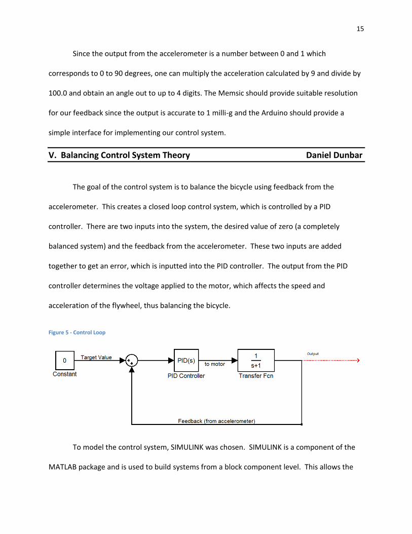
V. Balancing Control System Theory Daniel Dunbar
The goal of the control system is to balance the bicycle using feedback from the
accelerometer. This creates a closed loop control system, which is controlled by a PID
controller. There are two inputs into the system, the desired value of zero (a completely
balanced system) and the feedback from the accelerometer. These two inputs are added
together to get an error, which is inputted into the PID controller. The output from the PID
controller determines the voltage applied to the motor, which affects the speed and
acceleration of the flywheel, thus balancing the bicycle.
Figure 5 - Control Loop
To model the control system, SIMULINK was chosen. SIMULINK is a component of the
MATLAB package and is used to build systems from a block component level. This allows the
16
user to create a complete system within SIMULINK using standard blocks used in control system
theory. SIMULINK also has a PID tuner, which will automatically tune the gains for the P,I, and
D parts of the controller. If an accurate model of the plant can be obtained or designed, this is
an extremely effective tool that allows the user to look at the rise time, overshoot, etc. to find a
controller that will suit the application best.
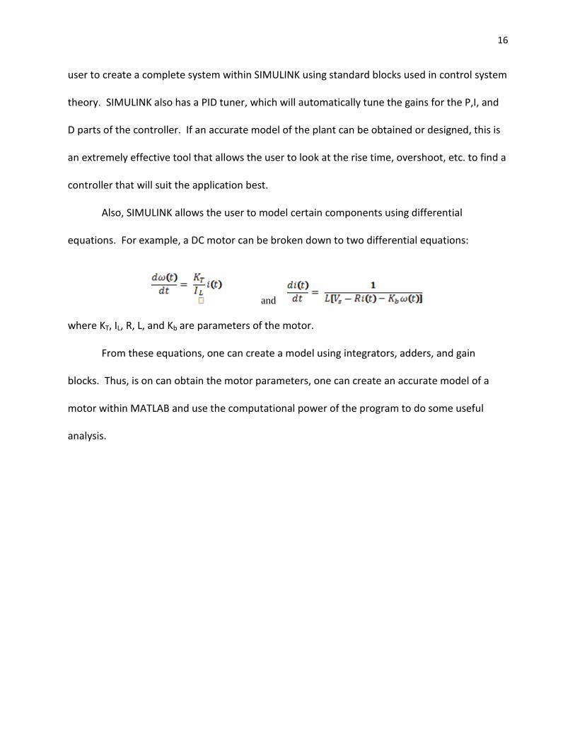
Also, SIMULINK allows the user to model certain components using differential
equations. For example, a DC motor can be broken down to two differential equations:
and
where KT, IL, R, L, and Kb are parameters of the motor.
From these equations, one can create a model using integrators, adders, and gain
blocks. Thus, is on can obtain the motor parameters, one can create an accurate model of a
motor within MATLAB and use the computational power of the program to do some useful
analysis.
17
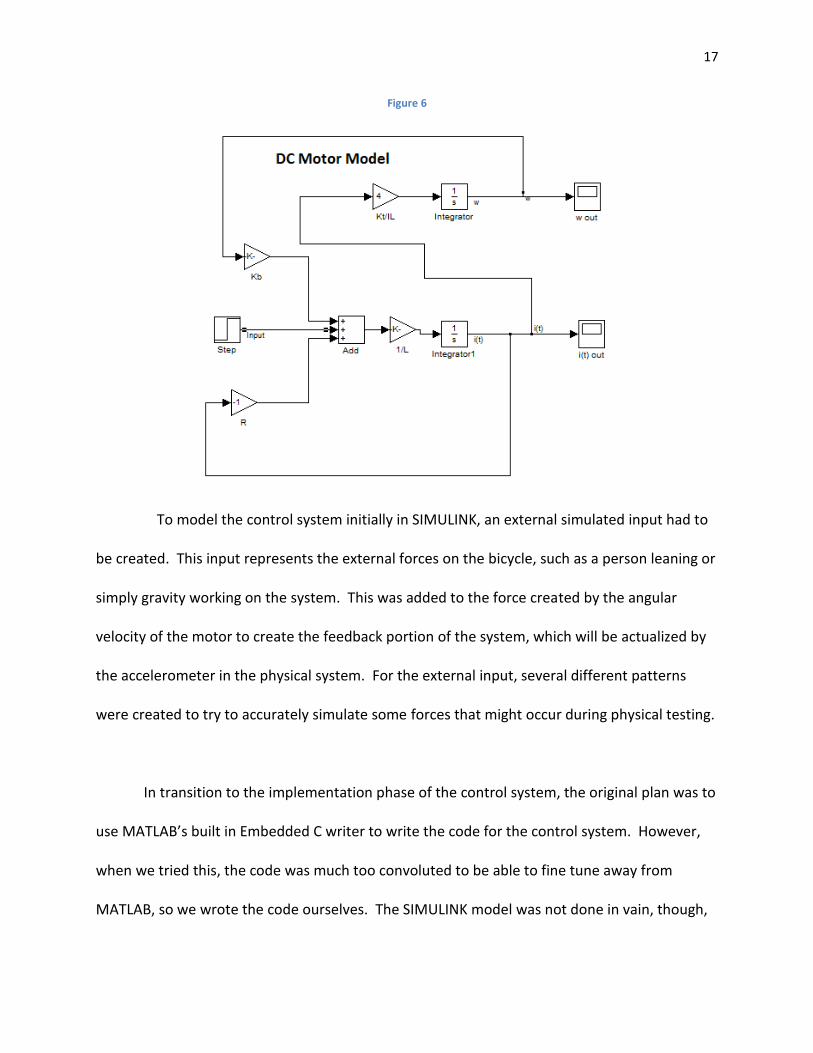
Figure 6
To model the control system initially in SIMULINK, an external simulated input had to
be created. This input represents the external forces on the bicycle, such as a person leaning or
simply gravity working on the system. This was added to the force created by the angular
velocity of the motor to create the feedback portion of the system, which will be actualized by
the accelerometer in the physical system. For the external input, several different patterns
were created to try to accurately simulate some forces that might occur during physical testing.
In transition to the implementation phase of the control system, the original plan was to
use MATLAB’s built in Embedded C writer to write the code for the control system. However,
when we tried this, the code was much too convoluted to be able to fine tune away from
MATLAB, so we wrote the code ourselves. The SIMULINK model was not done in vain, though,

18
because we are using it as a theoretical basis for our control system, and we are working to
develop an accurate transfer function that lines up with our actual motor under load. When we
achieve this, we will be able to use the SIMULINK model to tune the control system to optimize
performance.
The code, as seen below, was built as a function called from the main program. This
allows the program to be modularized for ease of reading and helps in the debug process. Also,
the KP, KD, and KI constants are at the top for easy access when tuning the control system.
#include "ControlSystem.h" void controlsys(int accel,int *dutycycle,unsigned char *direction) { int Kp = 1; //Kp = Proportional Constant int Ki = 2; //Ki = Integrator Constant int Kd = 3; //Kd = Derivative Constant int dt = 100; //dt = sampling frequency int integrator = 0; int lasterror = 0; int derivative; int error; *direction = 0; // sets the output sign to positive error = 0 - accel; integrator = integrator + (error/dt); derivative = (error - lasterror)*dt; lasterror = error; *dutycycle = Kp*error + Ki*integrator + Kd*derivative; if (*dutycycle<0){ *dutycycle = -1*(*dutycycle); *direction = 1;} if (*dutycycle>255) *dutycycle = 255;

19
}

20
VI. Embedded System Architecture Daniel Golden
For our balancing system, we incorporated a control loop which reads accelerometer
data, sends the data to the control system, and then sets a new corrective Duty Cycle and
direction pin for use by our motor controller. This control loop is shown in Figure 7 below.
Set Motor Duty
Cycle
Set Motor
Direction Pin
10ms has
passed
Start
No
Feed data to
control system
CONTROL
SYSTEM
Get new Duty
Cycle from Control
System
Get new Motor
Direction from
Control System
ACCELEROMETER
FILTER
Get filtered
Accelerometer
data
Initialize hardware
Figure 7 - Embedded System Control Loop
Accelerometer Filter
21
It has yet to be decided as to the best method for smoothing the data. At this moment,
we are not implementing a filter. One goal for the next cycle is to implement an accurate filter.
Control System
To execute the control system we chose to simply encapsulate the entire system into a
function that takes three arguments. One is the accelerometer data and the other two are
pointers to variables in the calling method’s scope which are updated by the control system
function.
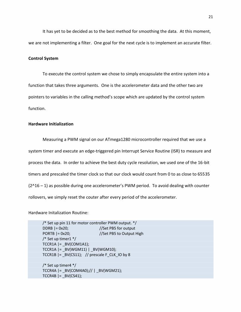
Hardware Initialization
Measuring a PWM signal on our ATmega1280 microcontroller required that we use a
system timer and execute an edge-triggered pin Interrupt Service Routine (ISR) to measure and
process the data. In order to achieve the best duty cycle resolution, we used one of the 16-bit
timers and prescaled the timer clock so that our clock would count from 0 to as close to 65535
(2^16 – 1) as possible during one accelerometer’s PWM period. To avoid dealing with counter
rollovers, we simply reset the couter after every period of the accelerometer.
Hardware Initalization Routine:
/* Set up pin 11 for motor controller PWM output. */ DDRB |= 0x20; //Set PB5 for output PORTB |= 0x20; //Set PB5 to Output High /* Set up timer1 */ TCCR1A |= _BV(COM1A1); TCCR1A |= _BV(WGM11) | _BV(WGM10); TCCR1B |= _BV(CS11); // prescale F_CLK_IO by 8 /* Set up timer4 */ TCCR4A |= _BV(COM4A0);// | _BV(WGM21); TCCR4B |= _BV(CS41);

22
/* This sets the input pins for Pin 49. Pin 49 is our Accelerometer PWM input. */ DDRL&= ~_BV(PL0);
PORTL&= ~_BV(PL0); /* Set up pin 12 for motor controller direction output. */ DDRB |= _BV(PB6); //Set PB6 to output PORTB |= _BV(PB6); //Set PB6 to Output high /* Enable Timer4 interrupts. Rising edge triggered initially */ TIMSK4 |= _BV(ICIE4); TCCR4B |= _BV(ICES4);
Accelerometer Triggered Interrupt
This is the routine that is executed on each edge of the PWM signal from the accelerometer:
SIGNAL(SIG_INPUT_CAPTURE4){ if ((TCCR4B & _BV(ICES4)) == _BV(ICES4)){// if currently rising edge triggered /* read the period of the accelerometer pwm signal (low byte first) */ AccPeriod = ICR4L; AccPeriod |= (ICR4H<<8); /* reset timer count to avoid dealing with rollovers */ TCNT4=0; /* switch to falling edge triggered interrupts */ TCCR4B &= ~_BV(ICES4); } else{ /* read the pulse width (time high) of the accelerometer pwm signal (low byte first) */ AccPulseWidth = ICR4L; AccPulseWidth |= (ICR4H<<8); /* switch to rising edge triggered interrupts */ TCCR4B |= _BV(ICES4); } }
Main Program Loop
The main program loop is the first code to execute on system power-on. This loop calls
the hardware initialization routine, enables interrupts, and then enters the infinite control loop:
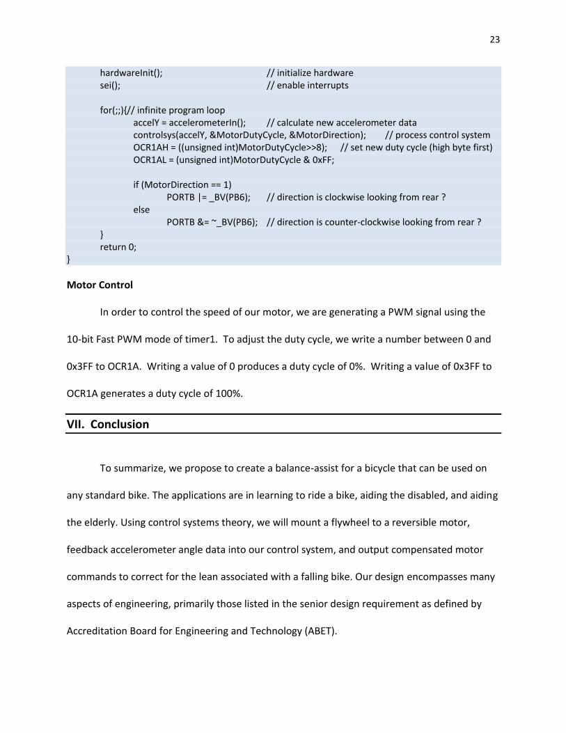
int main(){
23
hardwareInit(); // initialize hardware sei(); // enable interrupts for(;;){// infinite program loop accelY = accelerometerIn(); // calculate new accelerometer data controlsys(accelY, &MotorDutyCycle, &MotorDirection); // process control system OCR1AH = ((unsigned int)MotorDutyCycle>>8); // set new duty cycle (high byte first) OCR1AL = (unsigned int)MotorDutyCycle & 0xFF; if (MotorDirection == 1) PORTB |= _BV(PB6); // direction is clockwise looking from rear ? else PORTB &= ~_BV(PB6); // direction is counter-clockwise looking from rear ? } return 0; }
Motor Control
In order to control the speed of our motor, we are generating a PWM signal using the
10-bit Fast PWM mode of timer1. To adjust the duty cycle, we write a number between 0 and
0x3FF to OCR1A. Writing a value of 0 produces a duty cycle of 0%. Writing a value of 0x3FF to
OCR1A generates a duty cycle of 100%.
VII. Conclusion
To summarize, we propose to create a balance-assist for a bicycle that can be used on
any standard bike. The applications are in learning to ride a bike, aiding the disabled, and aiding
the elderly. Using control systems theory, we will mount a flywheel to a reversible motor,
feedback accelerometer angle data into our control system, and output compensated motor
commands to correct for the lean associated with a falling bike. Our design encompasses many
aspects of engineering, primarily those listed in the senior design requirement as defined by
Accreditation Board for Engineering and Technology (ABET).