assessment of scaled rotors for wind tunnel...
TRANSCRIPT

SANDIA REPORTSAND2015-XXXXUnlimited ReleasePrinted July 2015
Assessment of Scaled Rotors for Wind Tunnel Experiments
David C. Maniaci, Phillip Chiu, and Chris L. Kelley
Prepared bySandia National LaboratoriesAlbuquerque, New Mexico 87185 and Livermore, California 94550
Sandia National Laboratories is a multi-program laboratory managed and operated by Sandia Corporation, a wholly owned subsidiary of Lockheed Martin Corporation, for the U.S. Department of Energy's National Nuclear Security Administration under contract DE-AC04-94AL85000.
Approved for public release; further dissemination unlimited.
SAND2015-5850R

2
Issued by Sandia National Laboratories, operated for the United States Department of Energy by Sandia Corporation.
NOTICE: This report was prepared as an account of work sponsored by an agency of the United States Government. Neither the United States Government, nor any agency thereof, nor any of their employees, nor any of their contractors, subcontractors, or their employees, make any warranty, express or implied, or assume any legal liability or responsibility for the accuracy, completeness, or usefulness of any information, apparatus, product, or process disclosed, or represent that its use would not infringe privately owned rights. Reference herein to any specific commercial product, process, or service by trade name, trademark, manufacturer, or otherwise, does not necessarily constitute or imply its endorsement, recommendation, or favoring by the United States Government, any agency thereof, or any of their contractors or subcontractors. The views and opinions expressed herein do not necessarily state or reflect those of the United States Government, any agency thereof, or any of their contractors.
Printed in the United States of America. This report has been reproduced directly from the best available copy.
Available to DOE and DOE contractors fromU.S. Department of EnergyOffice of Scientific and Technical InformationP.O. Box 62Oak Ridge, TN 37831
Telephone: (865) 576-8401Facsimile: (865) 576-5728E-Mail: [email protected] ordering: http://www.osti.gov/scitech
Available to the public fromU.S. Department of CommerceNational Technical Information Service5301 Shawnee RdAlexandria, VA 22312
Telephone: (800) 553-6847Facsimile: (703) 605-6900E-Mail: [email protected] order: http://www.ntis.gov/search

3
SAND2015-XXXXUnlimited ReleasePrinted July 2015
Assessment of Scaled Rotors for Wind Tunnel Experiments
David C. Maniaci, Phillip Chiu, and Chris L. KelleyWind Energy Technologies
Sandia National LaboratoriesP.O. Box 5800
Albuquerque, New Mexico 87185-1124
Abstract
Rotor design and analysis work has been performed to support the conceptualization of a wind tunnel test focused on studying wake dynamics. This wind tunnel test would serve as part of a larger model validation campaign that is part of the Department of Energy Wind and Water Power Program’s Atmosphere to electrons (A2e) initiative. The first phase of this effort was directed towards designing a functionally scaled rotor based on the same design process and target full-scale turbine used for new rotors for the DOE/SNL SWiFT site. The second phase focused on assessing the capabilities of an already available rotor, the G1, designed and built by researchers at the Technical University of München.
4
CONTENTS
1. Introduction............................................................................................................................5
2. Rotor Specifications ...............................................................................................................7FX Rotor .....................................................................................................................7G1 Rotor .....................................................................................................................7
Airfoil data............................................................................................................................9FX Rotor .....................................................................................................................9G1 Rotor .....................................................................................................................9
3. Results .................................................................................................................................10Blade quantity distributions .................................................................................................10
Matching and .......................................................................................................14
4. Objectives Assessment .........................................................................................................17
5. Conclusion ...........................................................................................................................18
6. References............................................................................................................................19
Appendix A: G1 Rotor CP and CT ...........................................................................................20
FIGURES
Figure 1. Twist and non-dimensionalized chord distributions of the G1 and FX rotors. ...............8Figure 2. Lift and drag polars of the RG14 (TUM data) and FX 60-126 airfoils which are used along the majority of the G1 and FX rotors respectively. .............................................................9Figure 3. Blade non-dimensional circulation and axial induction factor for the G1 and FX rotors..................................................................................................................................................11Figure 4. Blade angle of attack and airflow angle for the G1 and FX rotors. .............................12Figure 5. Blade aerodynamic coefficients for the G1 and FX rotors. .........................................13Figure 6. Non-dimensional circulation for the G1 rotor and the FX rotor at its design condition..................................................................................................................................................14Figure 7. Axial induction factor for various matched parameters between the G1 and FX rotors..................................................................................................................................................15Figure 8. Non-dimensional circulation and its slope for various matched parameters between the G1 and FX rotors. .....................................................................................................................16
TABLES
Table 1. Conditions for matched metrics between the G1 and FX rotors. ..................................15

5
1. INTRODUCTION
The rotor is a critical part of wake experiments, as its aerodynamic and operating characteristics directly relate to downstream wake development. This report serves as a summary of rotor design and analysis work performed to support an A2e wind tunnel test. Initial efforts were directed towards designing a functionally scaled rotor based on the same design process and target full-scale turbine used for new rotors for the SWiFT site. Later, focus was placed on assessing the capabilities of an already available rotor, the G1, designed and built by researchers at the Technical University of München [1].
The wind tunnel test objectives are part of a validation hierarchy to assess a model’s ability to make predictions of wake development and dynamics that are relevant to full-scale wind turbines in a natural environment. Model prediction credibility is gained through a combination of direct model validation by measurements of the complete, complex system and through measurements of simpler, scaled experiments. Credibility is also gained through improved insight and knowledge of the governing physics for the complete system of interest.
A systematic approach was taken to identify a set of critical rotor requirements for these objectives. A group of wind turbine wake and rotor aerodynamics modelers were asked to prioritize rotor requirements relevant to studying the ability of a given model to predict wake development and dynamics relevant to the validation hierarchy. Through these discussions, a number of rotor requirements emerged. These requirements can be grouped into a number of categories:
Category 0 rotor requirements ensure that the rotor is sufficiently defined to serve as a validation case. In general, Category 0 requirements ensure a predictable and well-behaved rotor which minimizes the effects of phenomena which are difficult to capture in models and/or difficult to measure.
Category 1 rotor requirements ensure that the global rotor aerodynamic characteristics are similar to those of modern, utility scale turbines.
Category 2 rotor requirements focus on making the wind tunnel experiment directly comparable to the rotor at the SWiFT site [2]. These requirements further constrain the design choices specified in Category 1 and primarily seek to identify the effects of scale on wake development.

6
These rotor requirements are summarized in the following table.
Category 0 1.) Well defined rotor and nacelle geometry2.) Predictable rotor performance
a. Clean, smooth surfaceb. Predictable airfoil performance at operating Reynolds number
3.) Airfoil data tables defined at relevant Reynolds numbers and from a quality source
4.) Rotor operating conditions well defined
Category 1 Category 0, plus:
1.) Tip speed ratio must be greater than 7 to represent utility scale turbines.2.) Rotor loading must be high, meaning representative of a modern, utility scale
wind turbine.
Category 2 Category 1, plus:
1.) Tip speed ratio of 9 is desirable to make quantities directly comparable to the SWiFT turbines with minimal correction.
2.) Coefficient of thrust should match the scaled rotor at its design point (top of region II)
3.) Outboard spanwise loading, minimum error4.) Overall spanwise loading, minimum error5.) Slope of load distribution, minimum error
Through reports from and discussions with TUM researchers, it was determined that the G1 rotor meets the Category 0 and Category 1 rotor requirements. This conclusion means an experiment performed with this rotor would meet the minimum needs of modelers to assess their models for wake physics, assuming that all other aspects of the experiment meet their minimum requirements as well. Since the rotor meets the minimum requirements, the rotor analysis documented in this report focuses on the design objectives primarily in Category 2, which will add additional validation metrics and insight. Blade element momentum theory is used to analyze the characteristics of the G1 rotor. This rotor is compared to the FX rotor, a Sandia wind tunnel scale rotor designed to have the same non-dimensional circulation distribution as the NRT rotor at the design tip speed ratio. The FX rotor meets, to some degree, all three of the prioritized objectives and is therefore a good baseline to assess the G1 rotor.
7
2. ROTOR SPECIFICATIONSFX RotorThe FX rotor is a wind tunnel scale rotor designed at Sandia National Laboratories using the same design and scaling methodologies as used for the new SWiFT rotors. This rotor uses the Wortmann FX 60-126 (12.6% thickness to chord ratio) over the majority of its span (outboard of 42% span), with a cylindrical root which extends to 3.8% R. A series of transition airfoils are used in between the cylinder and FX 60-126.
The rotor was designed to have a non-dimensional circulation distribution matching that of the current conceptual NRT rotor at its design point while having sufficient absolute thickness along the majority of its span to allow for the insertion of instrumentation.
It is believed that matching the non-dimensional circulation distribution and tip speed ratio of two rotors leads to a reasonable level of wake similarity between designs. If this is indeed true, then it can be assumed that the FX rotor will have similar wake characteristics to the NRT rotor.
Rotor Radius 0.7002 m
Hub Radius 0.0370 m (5.3% R)Design RPM 859.2 rpmDesign TSR 9.0
G1 RotorThe G1 rotor is a scaled rotor developed for wind tunnel testing. Designed at the Technical University of München (TUM) for testing in the boundary layer wind tunnel at Politecnico di Milano , the G1 is one candidate rotor for a potential A2e wind tunnel experiment [1, 3]. This experiment will seek to validate the ability of a range of fidelity of modeling codes to predict various aspects of wake development behind a scaled wind turbine in multiple inflow conditions. The experiment will also seek data that will provide insight into the dominant physical phenomenon to further add credibility to the modeling codes and to give direction into how they can be improved.
The G1 is a wind tunnel scale three-bladed, adjustable pitch rotor designed to be operated in a wind tunnel. It uses a Rolf Girsberger RG14 airfoil (8.5% thickness to chord ratio) over the majority of its span (from 27% R out), with a cylindrical root which extends to 13.3% R. A transition airfoil is used between the cylinder and RG14. The rotor design was predicted to achieve maximum coefficient of power at a tip speed ratio of 6.6, although the rotor is typically operated at a tip speed ratio of 8.1 for testing by TUM [3].
Rotor Radius 0.550 mHub Radius 0.054 m (9.8% R)Design RPM 850.0 rpmDesign TSR 6.6
The chord and twist distributions for both rotors are compared in Figure 1.

8
Figure 1. Twist and non-dimensionalized chord distributions of the G1 and FX rotors.

9
Airfoil dataFX RotorThe source for the Wortmann FX airfoil data is based on data taken from wind tunnel measurements at 60,000 chord Reynolds numbers, which is within the operating range of this rotor [4].
G1 RotorMultiple sources exist for the RG14 airfoil data. One source comes from TUM [1]. Wind tunnel measurements were adjusted to match the experimental power coefficient using the method of [5] over the range . This data was then extrapolated using purportedly "standard methods" to . The RG14 has also been tested at the University of Illinois for Reynolds numbers ranging 60,000 to 300,000 .
Figure 2. Lift and drag polars of the RG14 (TUM data) and FX 60-126 airfoils which are used along the majority of the G1 and FX rotors respectively.

10
3. RESULTS
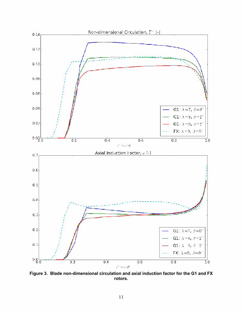
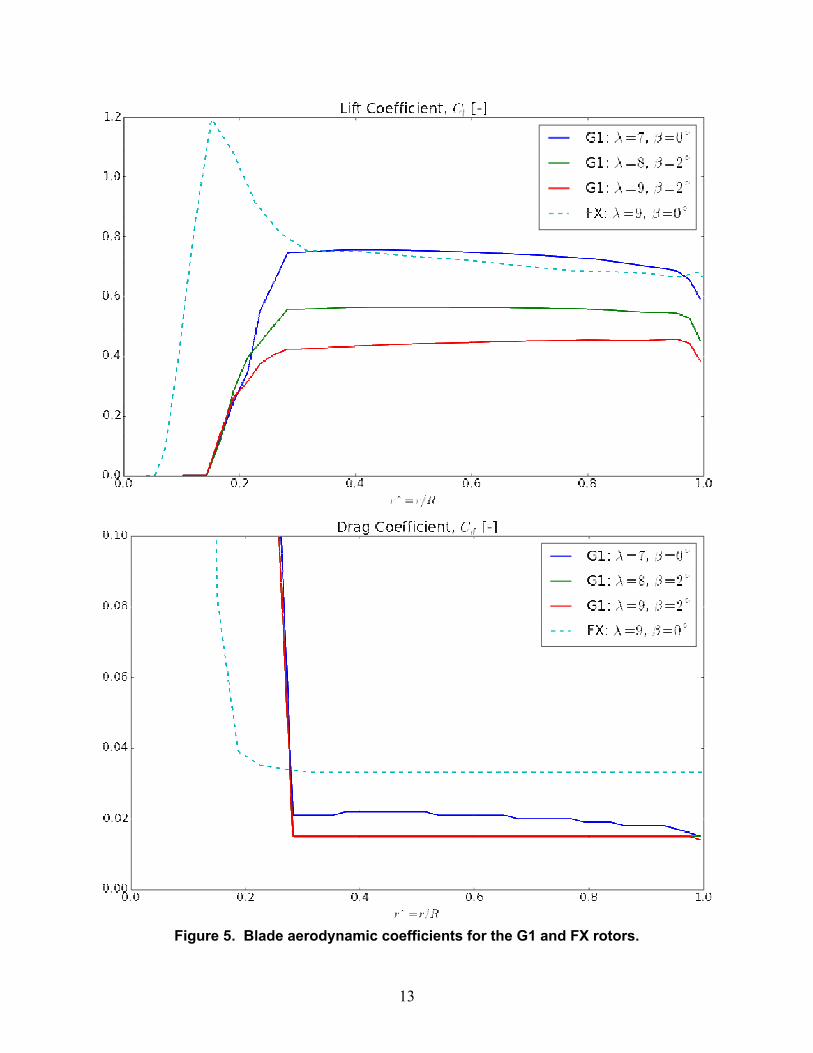
Blade quantity distributionsThe non-dimensional circulation distribution (Γ^* (r)) and tip speed ratio (λ) are the primary blade design conditions required for wake similarity. Thus, to have wake similarity between the G1 rotor and the NRT rotor, the Γ^* (r) and λ should be approximately the same. Since the FX rotor is matched in this way to the NRT rotor (which is matched to a utility scale rotor), the circulation distributions and other blade quantities of the G1 and FX rotor are compared below. The blade quantities are plotted for the G1 rotor at pitch β=0° and tip speed ratios of λ={7,8,9} in Figures 3-5. In addition, the blade quantities are plotted at the operating condition λ=9, β=2° –this condition corresponds to the case when the tip speed ratio is equal to that of the NRT design point, but the rotor thrust coefficient matches that of the G1 design condition. Also plotted are blade quantities for the FX rotor at its design operating condition.
11
Figure 3. Blade non-dimensional circulation and axial induction factor for the G1 and FX rotors.
12
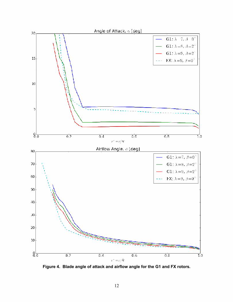
Figure 4. Blade angle of attack and airflow angle for the G1 and FX rotors.
13
Figure 5. Blade aerodynamic coefficients for the G1 and FX rotors.
14
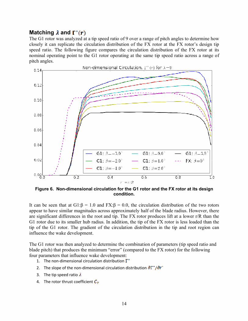
Matching and The G1 rotor was analyzed at a tip speed ratio of 9 over a range of pitch angles to determine how closely it can replicate the circulation distribution of the FX rotor at the FX rotor’s design tip speed ratio. The following figure compares the circulation distribution of the FX rotor at its nominal operating point to the G1 rotor operating at the same tip speed ratio across a range of pitch angles.
Figure 6. Non-dimensional circulation for the G1 rotor and the FX rotor at its design condition.
It can be seen that at G1:β = 1.0 and FX:β = 0.0, the circulation distribution of the two rotors appear to have similar magnitudes across approximately half of the blade radius. However, there are significant differences in the root and tip. The FX rotor produces lift at a lower r/R than the G1 rotor due to its smaller hub radius. In addition, the tip of the FX rotor is less loaded than the tip of the G1 rotor. The gradient of the circulation distribution in the tip and root region caninfluence the wake development.
The G1 rotor was then analyzed to determine the combination of parameters (tip speed ratio and blade pitch) that produces the minimum “error” (compared to the FX rotor) for the following four parameters that influence wake development:
1. The non-dimensional circulation distribution
2. The slope of the non-dimensional circulation distribution
3. The tip speed ratio
4. The rotor thrust coefficient

15
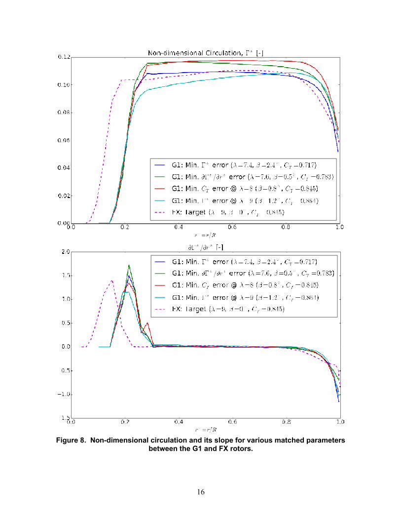
It is not possible to match all of these properties between the G1 and FX rotors at a single operating condition. By varying the tip speed ratio and pitch angle of the G1 rotor, the operating conditions were found for which the G1 rotor matched these metrics individually.The best-matched circulation distributions and circulation slope distributions were found by taking the sum of the square of errors between a candidate distribution and the target distribution for .Plotted below in Error! Reference source not found. and Error! Reference source not found.are the axial induction factor, circulation distribution, and slope for the four cases. The operating conditions for these four cases are summarized in the table below.
Table 1. Conditions for matched metrics between the G1 and FX rotors.
Case Goal Rotor [deg] error
1 Match G1 7.3 2.6 0.698 -17.40%
2 Match G1 7.6 0.5 0.783 -7.34%3 Match @ = 8 G1 8 0.8 0.845 0.00%
4 Match & G1 9 1.2 0.864 2.25%
Target FX 9 0 0.845 0.00%
Figure 7. Axial induction factor for various matched parameters between the G1 and FX rotors.
16
Figure 8. Non-dimensional circulation and its slope for various matched parameters between the G1 and FX rotors.

17
4. OBJECTIVES ASSESSMENT
The highest priority objectives are defined in Categories 0 and 1 in the Introduction. Satisfying these objectives would ensure that an experiment produces validation quality data for wake physics (Category 0) that are relevant to model prediction of full-scale, utility turbines (Category 1). The G1 rotor has a well-defined geometry with predictable performance that has been previously assess in the Milan wind tunnel. The airfoil has predictable performance at the relevant operating Reynolds number range and it has been two-dimensional airfoil data is available from a reputable source. The rotor has been operated at a tip speed ratio of approximately 8 with a coefficient of thrust that is close to that of the target, full-scale rotor used for the SWiFT scaled rotors.
The secondary objective is to have acceptable rotor loading over a range of tip speed ratios, as captured in Category 2, Objective 1 in the Introduction. Meeting this objective will allow systematic assessment of the effect of rotor characteristics on measured wake characteristics, mainly the effect of rotor tip speed ratio and loading. Both the G1 and the FX rotors can meet this objective partially by being operated at off design conditions through adjustments of the blade pitch and tip speed ratio. Fully meeting this objective would require testing two different rotors designed to operate at different tip speed ratios. Testing both the G1 and FX (or similar) rotors would fully meet this objective, and taking measurements at multiple operating points of a single rotor would still meet a significant amount of additional test objectives.
The tertiary objective is to match the tip speed ratio and loading, through functional scaling of the SWiFT rotors, and therefore of a utility scale turbine. This objective is captured in Category 2, Objectives 2-6. If the tip speed ratio and rotor loading are directly matched, as for the FX rotor, then insight can be gained as to the effect of the differences (e.g., scale, Reynolds number) between the wind tunnel experiment and the SWiFT experiment on the measured wake quantities. Based on the preceding analysis, the G1 rotor cannot be made to operate at a condition which would produce a wake exactly resembling that of the FX rotor (and thus the SWiFT rotors), and therefore does not meet this additional experimental objective. This objective was deemed as not critical for adding credibility to full-scale model predictions, and of lower priority as the Category 1 objectives. Additionally, there is uncertainty with how frequently inflow conditions at SWiFT will occur that would be required for direct comparisons to the wind tunnel results.
18
5. CONCLUSION
In summary, the G1 rotor meets the minimum requirements to perform a wind tunnel experiment that would be useful for validating the ability of models to predict the effect of wake phenomenon. This conclusion assumes that all other aspects of the wind tunnel experiment meet their requirements for a successful validation experiment as well. Wake metrics assessed from this rotor will be sufficiently relevant to full-scale, utility turbines as to be a valuable piece of thevalidation hierarchy. The G1 rotor can also be operated over a wide range as to be able to partially assess the effect of operating tip speed ratio on wake physics. One limitation of the G1 rotor is that its design tip speed ratio is different from that of the SWiFT rotors, and that the near-wake development would not be directly comparable between the two; however, this objective was not deemed as critical to providing validation data that would be valuable within the validation hierarchy.

19
6. REFERENCES
[1] F. Campagnolo, “Wind farm control validation by means of wind tunnel testing,” Munich, Germany.
[2] Resor, B.R., Maniaci, D.C., " Definition of the National Rotor Testbed: An Aeroelastically Relevant Research-Scale Wind Turbine Rotor," 32nd ASME Wind Energy Symposium, AIAA. 13-17 January 2014, National Harbor, Maryland.
[3] F. Campagnolo, “Rotor Design of the Scaled Wind Turbine Model G1,” Munich, Germany.
[4] Miley, S.J. “A Catalog of Low Reynolds Number Airfoil data for Wind Turbine Applications,” 1992. RFP-3387, UC-60. NTIS. Springfield, VA.
[5] C. L. Bottasso, S. Cacciola, and X. Iriarte, “Calibration of wind turbine lifting line models from rotor loads,” J. Wind Eng. Ind. Aerodyn., vol. 124, pp. 290–45, 2014.
[6] Lyon, C.A., Broeren, A.P., Giguere, P., Goplarathnam, A., and Selig, M.S., "Summary of Low-Speed Airfoil Data, Volume 3," 1997. SoarTech Publications. Virginia Beach, VA.

20
APPENDIX A: G1 ROTOR CP AND CT
Loads on the G1 rotor were investigated parametrically at tip speed ratios ranging from 3 to 9 and pitch angles from -5 to 15. Rotor CP and CT are plotted against these two parameters. These results show good agreement with BEM simulations of the G1 rotor performed in [1].
Rotor CP for the G1 rotor at varying pitch and tip speed ratios.

21
Rotor CT for the G1 rotor at varying pitch and tip speed ratios. The green line corresponds to CT = 8/9.
