assessment of health monitoring
TRANSCRIPT

International Journal of Computer Networks & Communications (IJCNC) Vol.7, No.5, September 2015
DOI : 10.5121/ijcnc.2015.7501 1
ASSESSMENT OF HEALTH MONITORING
SYSTEM USING SDL FORMAL METHOD
Anandi Giridharan and Pallapa Venkataram
Indian Institute of Science, Department of ECE, INDIA
ABSTRACT
Sensor nodes are highly mobile, which makes the application running on them face network related
problems like node failure, link failure, network level disconnection, scarcity of resources etc. Node failure
and Network fault are need to be monitored continuously by supervising the network status especially for
critical applications like Health Monitoring System. We propose Node Monitoring protocol (NMP) to
monitor the node good conditions using agents and ensure that node gets promised quality of service.
These Nodes senses environment and communicates important data to the sink or base station. To establish the correct event time, these nodes need to be synchronized with global clock. Therefore, time
synchronization is very important parameter. We have built a simulating environment for Validating Node
Monitoring Protocol (NMP) to assess the reliability of Health Monitoring systems. Formal Specification
and Description Language tool (SDL) has been used to validate the NMP at design time in order to
increase the confidence and efficiency of the system.
KEYWORDS SDL (Specification and Description Language), validation, Node Monitoring Protocol(NMP), safety and
liveness property.
1. INTRODUCTION
Potential of Sensor Networks in healthcare requires addressing a multitude of technical
challenges. Healthcare applications impose stringent requirements on system reliability,
efficiency and quality of service. In this paper, these challenges have been expanded and specification and validation using SDL tools attempts to confront them. The usage of Mobile
Agents gives the solution to the scalable problem in centralized network management[1].
Mobile Agents plays a vital role in node monitoring process[2]. Agents carry out management
function in an autonomous and efficient way[3]. This paper presents a formal model of the Node
Monitoring Protocol based on SDL using the Finite State Model. Formal description using SDL specifies the functional operation of the protocol and also helps in detecting design errors like
deadlock, livelock, unspecified reception, non-executable interactions, etc. The rest of the paper
is organized as follows. Section 2. details Health Monitoring system; Section 3. discusses on
Significance of Node Monitoring Protocol (NMP) in Ubiquitous environment. Section 4 presents Formal SDL specification of NMP. Section 5. illustrates verification of NMP. Section 6. Shows
various design errors like deadlock, unspecified reception, livelocks, etc. Section 6 draws the
conclusion.

International Journal of Computer Networks & Communications (IJCNC) Vol.7, No.5, September 2015
2
2. HEALTH MONITORING SYSTEM
Health monitoring systems is been very helpful to manage chronic disease, post-operation care,
and monitoring the safety of the patient. Wireless technologies integrated with mobile devices
form patient-friendly health monitoring systems. An health monitoring system is based on Wireless Body Sensor Networks. A set of physiological sensors can be integrated into a wearable
wireless body area computer assisted network that can be used for monitoring and restoring good
health. Sensor nodes that can be vulnerable to failures due to packet loss, Node failure etc. Thus
it is appropriate to provide sensor network of an system that gives alert messages to Health care givers. It is needed to validate the performance and robustness of the NMP at design time to
check the fault tolerance and also detect occurrence of failures and appropriately rectify them. In
our work we have simulated NMP using formal Specification and Description Language tool to observe the behavior of protocol . So that this could be more useful since verification at design
time could be extended to real time situations.
3.SIGNIFICANCE OF NODE MONITORING PROTOCOL IN
UBIQUITOUS ENVIRONMENT
In a Health Monitoring System, accurate and efficient monitoring of dynamically changing environment is very important in order to obtain the seamless transparency within mobile
devices[4]. Monitoring resource allocation scheme for the Unodes is very important to check
their Quality of Service. Static and Mobile Agent, based technology can provide a good
framework to develop Health Monitoring Systems for ubiquitous network environment, since it can do complicated works on behalf of a node independently and transparently[5]. Static Agent
sends a request to Mobile Agent to collect raw resource information from the nodes like some of
the health conditions like node failure, link failure, misbehaviour of the nodes in the network and to report the monitored results to them. Solution for entering the recovery upon validation is
worked out that maintains the health of Node Monitoring Protocol[6].
3.1.FINITE STATE MACHINE FORMALISM OF NODE MONITORING
PROTOCOL
An Finite State Machine M, is a 5-tuple A=(I, O, S, T, F) I is the Input, O is the output and S is
the states and F is the finite sets. The main system which runs at the central node, where Static Agent is deployed for collection of network status information. The Mobile monitoring system is
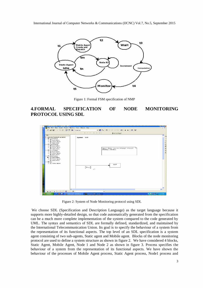
status monitoring segment, which runs in the migrated Mobile Agents. Figure 1. shows the State
transition sequence that illustrates that NMP is capable of delivering data without duplication and in right order. Initially Static Agent which resides in the main segment in idle state then if
requests arise, creates Mobile Agent and dispatches sending request M req to monitor the status
of the node, initiating the timer. Even if channel loses Mreq, time out occurs triggering
retransmission. and time channel correctly delivers the message. Now Mobile agent sends Request to Node 1 and in case channel loses the Request, Time out occurs and retransmission of
the data takes place. Request goes to Node 1 and Mobile Agent monitors the node collects the
status of the Node like node failure, link failure, energy level, throughput etc, and delivers to the Static Agent and goes into idle state again. Many important properties of requirement
specifications can be checked during requirements capture. First of all, requirements
characterizing the total behavior of a system may be expressed in terms of temporal modalities (dynamic requirements) including safety and liveness conditions.
International Journal of Computer Networks & Communications (IJCNC) Vol.7, No.5, September 2015
3
Figure 1: Formal FSM specification of NMP
4.FORMAL SPECIFICATION OF NODE MONITORING
PROTOCOL USING SDL
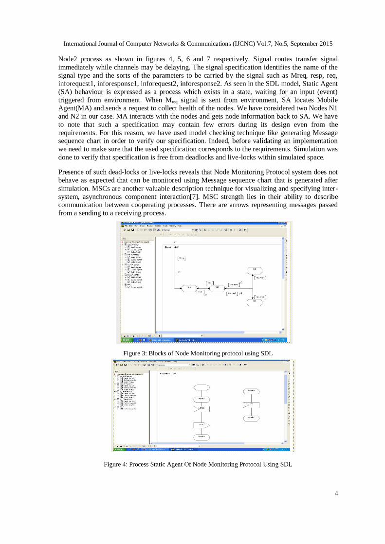
Figure 2: System of Node Monitoring protocol using SDL
We choose SDL (Specification and Description Language) as the target language because it supports more highly-detailed design, so that code automatically generated from the specification
can be a much more complete implementation of the system compared to the code generated by
UML. The syntax and semantics of SDL are formally defined, standardized, and maintained by the International Telecommunication Union. Its goal is to specify the behaviour of a system from
the representation of its functional aspects. The top level of an SDL specification is a system
agent consisting of two sub-agents, Static agent and Mobile agent. Blocks of the node monitoring
protocol are used to define a system structure as shown in figure 2. We have considered 4 blocks, Static Agent, Mobile Agent, Node 1 and Node 2 as shown in figure 3. Process specifies the
behaviour of a system from the representation of its functional aspects. We have shown the
behaviour of the processes of Mobile Agent process, Static Agent process, Node1 process and
International Journal of Computer Networks & Communications (IJCNC) Vol.7, No.5, September 2015
4
Node2 process as shown in figures 4, 5, 6 and 7 respectively. Signal routes transfer signal
immediately while channels may be delaying. The signal specification identifies the name of the
signal type and the sorts of the parameters to be carried by the signal such as Mreq, resp, req, inforequest1, inforesponse1, inforequest2, inforesponse2. As seen in the SDL model, Static Agent
(SA) behaviour is expressed as a process which exists in a state, waiting for an input (event)
triggered from environment. When Mreq signal is sent from environment, SA locates Mobile Agent(MA) and sends a request to collect health of the nodes. We have considered two Nodes N1
and N2 in our case. MA interacts with the nodes and gets node information back to SA. We have
to note that such a specification may contain few errors during its design even from the
requirements. For this reason, we have used model checking technique like generating Message sequence chart in order to verify our specification. Indeed, before validating an implementation
we need to make sure that the used specification corresponds to the requirements. Simulation was
done to verify that specification is free from deadlocks and live-locks within simulated space.
Presence of such dead-locks or live-locks reveals that Node Monitoring Protocol system does not
behave as expected that can be monitored using Message sequence chart that is generated after
simulation. MSCs are another valuable description technique for visualizing and specifying inter-
system, asynchronous component interaction[7]. MSC strength lies in their ability to describe communication between cooperating processes. There are arrows representing messages passed
from a sending to a receiving process.
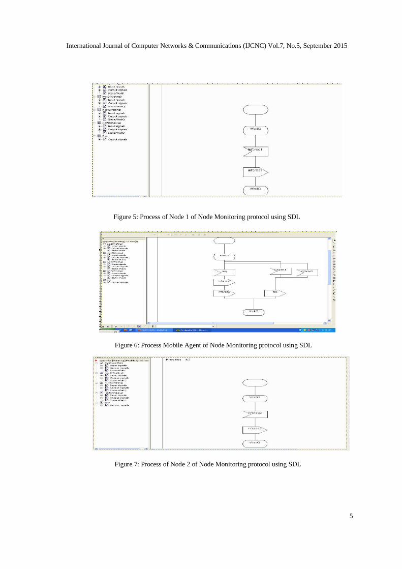
Figure 3: Blocks of Node Monitoring protocol using SDL
Figure 4: Process Static Agent Of Node Monitoring Protocol Using SDL
International Journal of Computer Networks & Communications (IJCNC) Vol.7, No.5, September 2015
5
Figure 5: Process of Node 1 of Node Monitoring protocol using SDL
Figure 6: Process Mobile Agent of Node Monitoring protocol using SDL
Figure 7: Process of Node 2 of Node Monitoring protocol using SDL

International Journal of Computer Networks & Communications (IJCNC) Vol.7, No.5, September 2015
6
4.2. VERIFICATION OF NMP
We manually derived the EFSM directly from the IETF specification . The verification process
consists to map the traces of I/O events (messages received and sent) recorded on each node, with
the specification. As seen in Figure 8. C1 is the outgoing channel of the Static Agent and C2 is the outgoing channel of the Mobile Agent.
Undesired events, such as node crash, packet loss may undermine effect of sensor network. Their
influence need to be properly assessed/ from early stages of development process to minimize the probability of unexpected errors during use. System verification and model checking was
conducted to check liveness and safety property and also static verification was done by
generating sequence of events and resulting actions were analysed. Sequence of random undesirable events were generated and action based on bottleneck were also analysed.
Figure 8: Verification of NMP
Liveness property: In system verification and model checking, liveness properties are
requirements that something good must eventually happen For example, with every request from
Static Agent, Node status should be collected by Mobile Agent and protocol should terminate
successfully.
Proof of Liveness Property
Liveness property is taken care in design process, they include termination of the protocol. From
above transition state, we observe that message M req and Response are transmitted from and to
Static Agent respectively even under the conditions of frame and acknowledgement loss and
NMP returns to its terminator state. Hence Specified messages have been transmitted and received correctly.
Safety property: Bad things will not happen. For example. Node Monitoring Protocol should operate properly. Message Sequence Chart shows the behaviour of the normal NMP as shown in
the figure 9. We chose to rely on the FSM formalism because it suits very well to the analysis of
data flows and allows to put constraints on the variables of the transitions.

International Journal of Computer Networks & Communications (IJCNC) Vol.7, No.5, September 2015
7
Proof of Safely properties
From transitions, we can see handling of lost frames and Acknowledgement are done by
retransmission and no redundancy has occurred by sending two duplicates of the same message.
Hence safety property.
Figure 9: Message Sequence chart showing expected communication between various entities
5.VALIDATION OF NODE MONITORING PROTOCOL Failures may also arise at run-time, for example, because of the loss of network connectivity.
node failure, link failure etc. The design of the framework must ensure its ability to hold good
under increasing load, increasing complexity of requests and increasing size of resulting
composite services[8]. Validation ensures that the protocol specifications will not get into protocol design errors. (Deadlock, unspecified reception, livelock etc). We have used Message
sequence charts for validation of Node Monitoring Protocol. MSCs were used to identify different
kinds of errors like Deadlock, unreachable states, livelocks etc.
5.1. DEADLOCK
Figure 10: Deadlock error in Node Monitoring protocol
International Journal of Computer Networks & Communications (IJCNC) Vol.7, No.5, September 2015
8
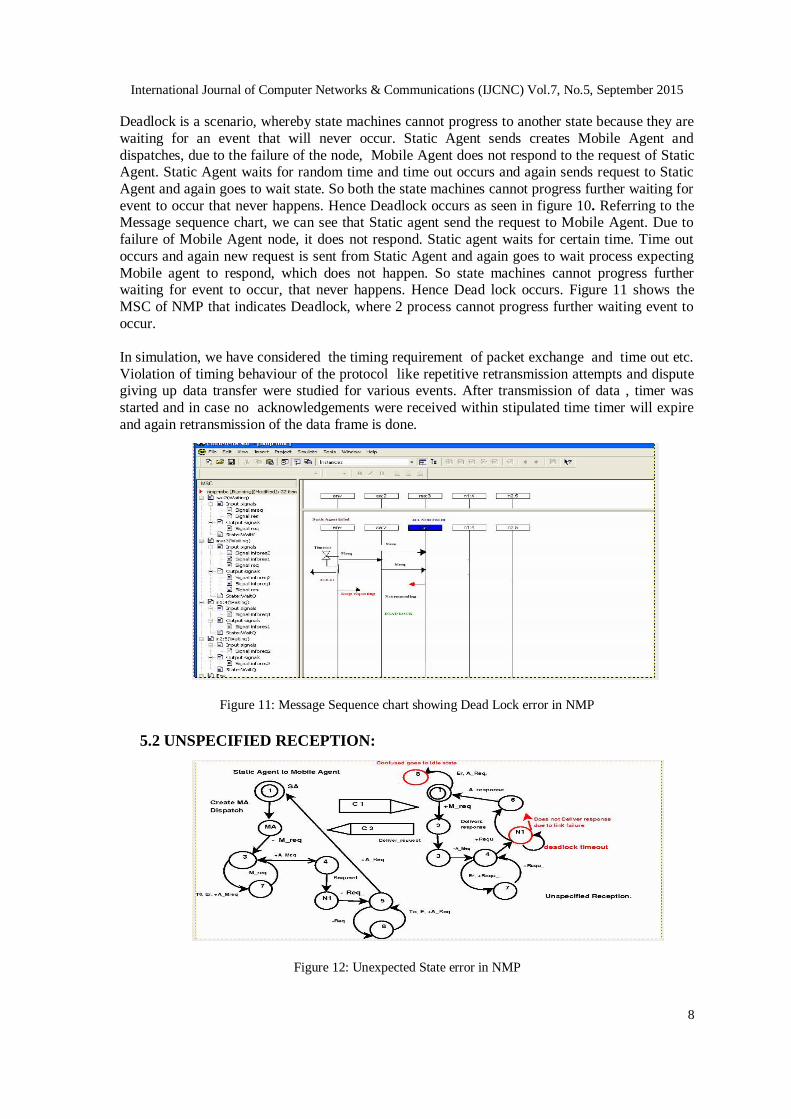
Deadlock is a scenario, whereby state machines cannot progress to another state because they are
waiting for an event that will never occur. Static Agent sends creates Mobile Agent and
dispatches, due to the failure of the node, Mobile Agent does not respond to the request of Static Agent. Static Agent waits for random time and time out occurs and again sends request to Static
Agent and again goes to wait state. So both the state machines cannot progress further waiting for
event to occur that never happens. Hence Deadlock occurs as seen in figure 10. Referring to the Message sequence chart, we can see that Static agent send the request to Mobile Agent. Due to
failure of Mobile Agent node, it does not respond. Static agent waits for certain time. Time out
occurs and again new request is sent from Static Agent and again goes to wait process expecting
Mobile agent to respond, which does not happen. So state machines cannot progress further waiting for event to occur, that never happens. Hence Dead lock occurs. Figure 11 shows the
MSC of NMP that indicates Deadlock, where 2 process cannot progress further waiting event to
occur.
In simulation, we have considered the timing requirement of packet exchange and time out etc.
Violation of timing behaviour of the protocol like repetitive retransmission attempts and dispute giving up data transfer were studied for various events. After transmission of data , timer was
started and in case no acknowledgements were received within stipulated time timer will expire
and again retransmission of the data frame is done.
Figure 11: Message Sequence chart showing Dead Lock error in NMP
5.2 UNSPECIFIED RECEPTION:
Figure 12: Unexpected State error in NMP

International Journal of Computer Networks & Communications (IJCNC) Vol.7, No.5, September 2015
9
Use of timers may prevent deadlocks, but their use may result in states that are never reached if
the specification is faulty[9]. In our simulation, When there was no request from environment,
Static Agent is in idle state. Once the request comes from environment , Static Agent sends request to Mobile Agent. Mobile agent goes to Nodes and collects their status. In this case error
will propagate because a generic deadlock timer expired that was unaware of the state specific
actions to take at this point. So due to ambiguity, Static Agent is not in position to decide what state it should be, hence goes idle. Even through Mobile Agent is ready with node status, Static
Agent is not a possible to accept the information as shown in figure 12. Figure 13. shows the
MSC indicating the unexpected state error due to ambiguity.
Figure 13: Message Sequence chart showing Unexpected State error in NMP
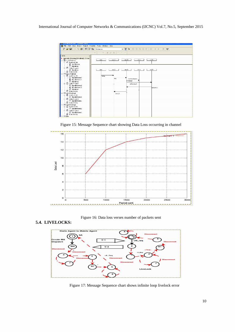
5.3. DATA LOSS:
As indicated in figure 14, request from Node1 gets lost in channel and no response from Mobile
Agent regarding status of the Node. Figure 15. shows that Request sent by Static Agent to Mobile
Agent and request gets lost in the channel, Response comes from only from Node2 to Mobile Agent. Data loss occurs, when one or more packets of data travelling across a network fail to
reach their destination. Data loss can be caused by a number of factors, including packet drop
because of channel congestion, rejected corrupted packets, faulty networking hardware. As seen in the figure 16, it shows that the data loss increases if more number of packets are sent. Hence
throughput will be less due to the number of retransmission.
Figure 14: Data Loss occurring in channel
International Journal of Computer Networks & Communications (IJCNC) Vol.7, No.5, September 2015
10
Figure 15: Message Sequence chart showing Data Loss occurring in channel
Figure 16: Data loss verses number of packets sent
5.4. LIVELOCKS:
Figure 17: Message Sequence chart shows infinite loop livelock error

International Journal of Computer Networks & Communications (IJCNC) Vol.7, No.5, September 2015
11
Livelock is a scenario whereby sequences of messages is repeated in an endless loop as shown in
figure 17. Without appropriate safety mechanisms livelock can consume all of the resources in a
network. Livelocks can occur depending on the value of data, such as an entity forwarding a message to itself . MSC indicates, how sequence of messages are repeated in an endless manner
as shown in figure 18.
Figure 18: Message Sequence chart shows infinite loop livelock error
6. SIMULATION AND RESULTS
We simulated on five to fifteen nodes creating basic events like : Disconnect (node i) at certain time Ti , Stopping (node j) at certain Time Tj , Sending event at time Tk and observing the
output actions. Checking for nodes that were not reachable. Simulation was conducted by
randomly selecting the events and time-points. We Observed, It was found that various errors
increases as the traffic on the network increased.
7. CONCLUSION
This paper has presented verification and validation model for the Node Monitoring protocol in
assessment of Health Monitoring System. It includes a formal specification of the protocol using
Specification and Description Language and Message sequence charts a method and a tool for the automated test generation of scenarios. Validation checks for safety and liveness property of the
protocol to check proper functioning and termination of protocol and validation model presents
several advantages[10][11]. First, the design of a formal specification from which tests are generated contributes to eliminate design errors like Deadlock, unspecified receptions and
livelocks and using SDL, it is shown that design flaws and ambiguity introduced in informally
specified, textual protocols can be avoided if protocol is formally modelled.
REFERENCES
[1] Tatjana Kapus. “Specifying System Families with TLA+”, Recent Researches in Engineering
Education and Software Engineering, pp. 98-103, (202).
[2] Sarada Prasad Gochhayat and Pallapa Venkataram, Performance Analysis of Node Monitoring
Protocol in Ubiquitous Networks, Ubiquitous Computing and Communication Journal, vol 8, issue
1, May 2013.
[3] Richard Castanet, Marcien MacKaya, Patrice Laurenscot , A Multi-service and Multi-protocol
Validation Platform Experimentation Results, Testing of Communicating Systems Lecture Notes in
Computer Science Volume 2978, 2004, pp 17-32. [4] C.Bohoris, G. Pavlou, and H. Cruick- shank, Using mobile agents for network performance
management, in Network Operations and Management Symposium, IEEE/IFIP,2000,pp. 637652.

International Journal of Computer Networks & Communications (IJCNC) Vol.7, No.5, September 2015
12
[5] H.H. To, S. Krishnaswamy, and B. Srinivasan, Mobile agents for network management when and
when not,in Proceedings of the 2005 ACM symposium on Applied computing, SAC 05. NewYork,
NY, USA: ACM,2005, pp. 4753.
[6] M.Konaand C. Z. Xu, A framework for network management using mobile agents, in Proceedings of
the 16th International Parallel all optical networks, Network and Service and Distributed Processing
Symposium, ser. IPDPS'02. Washington, DC, USA, IEEE Computer Society, 2002, pp. 714.
[7] D.Gavalas, G. E. Tsekouras, and C. Anagnos-topoulos, A mobile agent plat- form for distributed
network and systems management, J. Syst. Softw., vol. 82, no. 2, Feb. 2009, pp.355371. [8] D.Gavalas, D. Greenwood, M. Ghanbari, and M.O Mahony, Using mobile agents for distributed
network performance management, in 3rd International Workshop on Intelligent Agents for
Telecommunication Applications, 1999.
[9] Channappagoudar Mallikarjun B, Pallapa Venkataram, Mobile agent based node monitoring
protocol for MANETs, World Academy of Science, Engineer- ing and Technology. International
Journal of Computer, Information, Systems and Control Engineering Vol:8 No:1, 2014,vol 8, No:1,
2014.
[10] Ameer A. Abbasi, Mohamed F. Younis, Senior Member. IEEE, and Uthman A. Baroudi , Re
covering from a node failure in wireless Sensor, Actor Network with Minimal Topology changes ,
IEEE Transactions on vehicular technology, vol.62, no.1 Jan 2013.
[11] G. Wang et al., Sensor relocation in mobile sensor networks, in proc. 24 th Annual. Joint
Conf.INFOCOM, Miami, FL, Mar. 2005,pp.2302- 2312.
Authors
Anandi Giridharan, received MSc(Engg) from Indian Institute of Science. She
currently working as Senior Scientific Officer in ECE Department, Indian Institute
Science, Bangalore. Her Research Interest are in area of Ubiquitous Learning, Communication Protocols and Multimedia systems.
Prof. Venkataram Pallapa received his Ph.D. Degree in Information Sciences from
the University of Sheffield, England, in 1986. He is currently the chairman for centre
for continuing education, and also a Professor in the Department of Electrical
Communication Engineering, Indian Institute of Science, Bangalore, India.
Dr. Pallapa's research interests are in the areas of Wireless Ubiquitous Networks,
Communication Protocols, Computation Intelligence applications in Communication Networks and
Multimedia Systems.
Dr. Pallapa is the holder of a Distinguished Visitor Diploma from the Orrego University, Trujillo, PERU. He has published over 150 papers in International/national Journals/conferences. Written three books:
Mobile and wireless application security, Tata McGraw-Hill, Communication Protocol Engineering,
publications Prentice-Hall of India (PHI), New Delhi, 2014 (Co-author: Sunil Manvi, B Satish Babu) and
Multimedia: Concepts & Communication, Darling Kinderley(India) Pvt. Ltd., licensees of Pearson
Education in South Asia, 2006. Written chapters for two different books, and a guest editor to the IISc
Journal for a special issue on Multimedia Wireless Networks. He has received best paper awards at
GLOBECOM'93 and INM'95 and also CDIL (Commu nication Devices India Ltd) for a paper published in
IETE Journal. He is a Fellow of IEE (England), Fellow of IETE(India) and a Senior member of IEEE
Computer Society.