assessment of a fuel cell powered air taxi in urban flight
TRANSCRIPT

1
Assessment of a Fuel Cell Powered Air Taxi
in Urban Flight Conditions
M. Husemann1, C. Glaser2, E. Stumpf3
Institute of Aerospace Systems (ILR), RWTH Aachen University, 52062 Aachen, Germany
This paper presents a first estimation of potential impacts on the flight operations of small
air taxis in urban areas using a fuel cell instead of a battery as an energy resource. The
expanding application of electric components is seen as a possibility to reduce operating costs
and environmental impacts in the form of noise and pollutant emissions due to lower
consumption of fossil fuels. The majority of such designs have so far been based on the use of
(not yet) sufficiently efficient batteries. Long charging times, possible overheating or a limited
service life in the form of limited charging cycles pose a challenge to the development of such
aircraft. Parameter studies are conducted to identify possible advantages of using a fuel cell.
In particular, the range and payload capacity ist investigated and first effects on the cost
structure will be presented. The evaluation of the studies shows that the use of fuel cells enables
significantly longer ranges than the use of batteries. In addition, the range potential gained
can be used, for example, to transport more payload over the same distance. Furthermore, the
technological maturity in the form of the individual energy density and the weight of the
powertrain unit has a significant effect on the cost structure. Fuel cells therefore have a high
potential for applications in the mobility sector, but still require extensive research efforts.
I. Introduction
Increasing traffic volume due to advanced technologies and growing mobility demand often leads to heavy traffic
and circumstantial routing, especially in metropolitan areas. Ambitious goals, for example in the form of a door-to-
door journey within Europe of maximum four hours set by "Flightpath 2050" and restrictive environmental
requirements, are additionally increasing the pressure to develop efficient mobility technologies and solutions. In
passenger and freight transportation, however, air transportation was largely omitted as the third dimension for short
distances of up to 500 km. Ground-based transportation infrastructures has been offering economic and organizational
advantages in terms of cost and time factors and were clearly superior to air traffic on short routes. Also, air
transportation is affected by additional, time-consuming access to and from airports, which are often built outside
urban areas for reasons of noise and environmental protection.
With the introduction of low-noise and electric powertrains and the continuous technological progress of vertical
(VTOL) and short take-off and landing (STOL) aircraft, passenger transportation in the short-haul sector is becoming
increasingly important. On-demand air vehicles, also called air taxis, have the potential to overcome previous
restrictions in the mobility sector and to fundamentally restructure regional and urban passenger transportation.
Depending on the mission and its individual topographical (e.g., bay areas or hills) and architectonic (e.g., high-rise
buildings and narrow streets) circumstances, different aircraft types will be appropriate: VTOL concepts are
particularly suitable for inner-city operations and feeder traffic to airports, whereas fixed-wing aircraft are largely
used for longer distances in regional air traffic. Research and development of such vehicles has been mainly focused
on the implementation of high-performance electric motors powered by sufficiently large batteries. Long charging
times, possible overheating of the energy storage and propulsion units as well as limited energy density are still an
obstacle to the successful implementation of a smooth on-demand air transportation system. The application of fuel
cells, which have mainly been used and tested in the automotive industry, offers a serious alternative to battery systems
1 Research Associate and Ph.D. candidate, Institute of Aerospace Systems (ILR), RWTH Aachen University,
Wuellnerstrasse 7, 52062 Aachen, Germany, [email protected]. 2 Graduate Student, Institute of Aerospace Systems (ILR), RWTH Aachen University, Wuellnerstrasse 7, 52062
Aachen, Germany, [email protected]. 3 Head of Institute, Institute of Aerospace Systems (ILR), RWTH Aachen University, Wuellnerstrasse 7, 52062
Aachen, Germany, [email protected].

2
due to short refueling times and potentially longer ranges. The use in air transportation not only facilitates the
avoidance of many technical complexities as mentioned before, but also allows a more flexible handling and thus the
operation of a cheaper on-demand air transportation system.
After a short overview of the central properties of fuel cells and their functionalities (see Section II), the reference
aircraft Vahana by A³ as well as its design and performance parameters will be presented (see Section III). By carrying
out parameter studies, central effects on flight operations will be investigated if a comparable fuel cell is implemented
as main energy source instead of a battery, while small batteries are retained for possible power peaks (see Section
IV). Conspicuous changes and important influences will be identified and analyzed with regard to associated
advantages. Finally, a short assessment of possible effects of economic parameters is made.
II. The Concept of Fuel Cells
The first practical concept of a fuel cell was introduced in 1932 in the United Kingdom by F.T. Bacon leading to
a 1.5 kW fuel cell version used during the NASA Apollo program that started in 1961. Although current fuel cell
concepts differ both in weight and available power, it was the successful application at that time that resulted in a
massive growth in fuel cell research. [19] Today’s applications of fuel cells include civil transportation (by sea, land
and air), military purposes and space missions. [4]
A. Fundamentals of Fuel Cells
The composition and functional principle of fuel cells are similar to those of batteries since chemical energy is
converted into electrical energy for further usage. In contrast to conventional technologies such as combustion engines,
the chemical energy – stored in hydrogen – is transformed directly into electricity without generating heat first. [11]
A fuel cell generally consists of an anode and a cathode which are separated by a layer of electrolyte. Once the cathode
is exposed to oxygen and the anode to hydrogen, a circuit is formed externally as depicted in Fig. 1. For this reason,
fuel cells are also classified as galvanic cells. Additional information on the general structure can be found in [3]. As
the detailed design and structure of the electrodes is not the subject of this paper, it will not be discussed any further.
To ensure permeability towards gas or liquid, both electrodes are designed sufficiently porous. Unlike anode and
cathode, the electrolyte is meant to be impermeable. The overall chemical reaction occurring in fuel cells can be
described as: [4]
𝐻2 +1
2𝑂2 → 𝐻2𝑂. (2.1)
More specifically, the anode oxidizes hydrogen according to the following equation; the protons migrate to the
cathode, whereas the electrons enter the external circuit:
𝐻2 → 2𝐻+ + 2𝑒−. (2.2)
Oxygen from ambient air is split into double-negatively charged oxygen ions (O2-):
𝑂2 + 4𝑒− → 2𝑂2−. (2.3)
Finally, oxygen ions and protons form water at the cathode according to:
𝑂2− + 2𝐻+ → 𝐻2𝑂. (2.4)
The electrochemical reactions taking place at both electrodes determine their equilibrium potential. Possible
differences in potentials result in a fuel cell voltage of 1.23 V at 25 °C conditions. [4] To increase voltage, several
individual fuel cells need to be interconnected to provide the total power required for the actual application. Also,
since fuel cells are more suitable for a constant output of electrical power and cannot react as quickly as conventional
combustion engines or batteries to varying power requirements, it is mostly necessary to use an additional battery to
buffer possible power peaks. Other crucial design parameters such as space, vehicle dimensions and weight must be
taken into consideration when integrating appropriate fuel cells.

3
Fig. 1: Illustration of a hydrogen/ oxygen fuel cell setup (proton exchange membrane fuel cell, PEMFC) [4]
The definition of following two characteristics (volumetric and gravimetric power) allows a comparison between
fuel cells and other energy conversion systems. Volumetric power density is defined as [12]:
𝑝𝑜𝑤𝑒𝑟 𝑑𝑒𝑛𝑠𝑖𝑡𝑦 =𝑝𝑜𝑤𝑒𝑟
𝑣𝑜𝑙𝑢𝑚𝑒 , (2.5)
whereas gravimetric power density (also defined as specific power) gives:
𝑠𝑝𝑒𝑐𝑖𝑓𝑖𝑐 𝑝𝑜𝑤𝑒𝑟 =𝑝𝑜𝑤𝑒𝑟
𝑚𝑎𝑠𝑠 . (2.6)
State of the art Proton-Exchange Membrane (PEM) fuel cells in aeronautical applications can achieve about 1.5-
1.6 kWh/kg in the range of 100 kW [20,7] but are expected to increase up to 8 kWh/kg in the near future. [7] For
comparison, the Honeywell TPE 331-10 turboprop engine has a specific power of 4.38 kW/kg, the Pratt & Whitney
PW545B turbofan operates at 10.86 kWh/kg. [5] The low specific power of fuel cells is one of the main disadvantages
for high power applications such as long-range flights. Therefore, hybrid propulsion systems (combination of different
propulsion types such as batteries or fuel cells with combustion engines) are prioritized for those applications. [5]
However, since only ranges from 10-100 km with an average power demand of several hundreds of kW in urban
applications are subject of this paper, hybrid options are not further discussed.
Fuel cells provide several advantages making them a promising alternative in propulsion systems. Most notably,
they produce very low greenhouse emissions, a characteristic that is becoming more and more important in terms of
climate change due to environmental restrictions and regulatory specifications. In fact, only water is emitted as a result
of the chemical process, yet a substantial part of the greenhouse effect. The production and distribution of needed
hydrogen causes greenhouse emissions which must be considered when a holistic comparison with other propulsion
types is made. [12] Fuel cells are not directly dependent on fossil fuels and have a significant higher efficiency
compared to conventional jet engines. Especially their high energy density makes them superior to battery cells. [9]
Also, energy is produced as long as fuel is supplied, which means that no recharging is required. The refueling process
of fuel cells takes significantly less time than recharging a battery. [5] In space applications, produced water is used
as additional water supply. [19] Fuel cells can be applied in a wide range of applications from microwatts to megawatts
due to their modularity and are highly reliable due to few moving parts and overall simplicity. [12]

4
B. Types of Fuel Cells
Cell types are generally classified by the utilized electrolyte. The only type not following this classification
approach is the Direct Methanol Fuel Cell (DMFC) where methanol as fuel is exposed to the anode. [4] A second
classification can be done by sorting the types of fuel cells in terms of their operating temperature. This leads to low-
temperature fuel cells with operating temperatures between 30-220 °C and high-temperature cells operating between
500-1000 °C. Currently six classes of fuel cells are considered feasible and most promising for mobility options and
vehicle designs. All types of fuel cells and their respective applications are listed in Table 1. [12]
Table 1 Types of fuel cells [12]
Fuel Cell Type Mobile Ion Operating Temperature Applications and Remarks
Alkaline (AFC) 𝑂𝐻− 50-200 °C Space vehicles
Proton exchange membrane (PEMFC) 𝐻+ 30-100 °C Vehicles and mobile applications
Direct methanol (DMFC) 𝐻+ 20-90 °C Low power portable electronic systems
Phosphoric acid (PAFC) 𝐻+ ~220 °C Small power plants
Molten carbonate (MCFC) 𝐶𝑂32− ~650 °C Medium-large power plants
Solid oxide (SOFC) 𝑂2− 500-1000 °C Multi MW power plants
For mobile applications such as vehicles and small aircraft concepts, PEMFC are considered most suitable due to
several reasons. [22,4,23] Those advantages include characteristics such as: [4]
lightweight
simple design
low operating temperature
higher power density
high energy conversion efficiency.
The PEMFC is also used in the Toyota MIRAI [23] as well as in different UAV concepts. [16] Consequently, the
proton exchange membrane fuel cell is chosen as viable option for the objective of this paper and all other types are
not further considered.
C. Energy Storage Methods
Although hydrogen shows one of the highest gravimetric densities (energy per weight) of all elements, it is the
low volumetric energy density (energy per volume) that calls for special storage technologies since the overall weight
and available space is crucial in air vehicles. Hydrogen can be stored either under pressure, liquid or in hybrids. [20]
In latter options, the hydrogen is stored in metals such as magnesia. Due to high energetic effort and system weight,
metal hybrid storage only has been used in research. [20] To reach a liquid state, hydrogen must be cooled down to
21 Kelvin. In this state, the volumetric energy density is significantly higher, but because of the energy necessary to
cool down the hydrogen and the boil-off phenomena (due to imperfect isolation, the liquid hydrogen heats up and goes
back into gaseous state), liquid hydrogen storage methods are generally not considered in the field of terrestrial
vehicles. [20] As long as hydrogen consumption is comparatively high, however, this problem is not predominant. It
should be noted, that in commercial aeronautical applications, liquid hydrogen storage is subject to promising research
[21]. In the field of vehicles and small aircraft high pressure storage is considered most viable. [23, 20] Hydrogen is
stored at 350-700 bar in carbon fiber tanks and, hence, the volumetric energy density can be significantly improved.
[23, 20] An overview of the most common energy storage systems is given in Fig. 2. [6] It must be mentioned, that
both liquid and pressure storage of hydrogen is far superior compared to batteries.

5
Fig. 2: Energy characteristics of energy storage systems [6]
D. Equivalent Specific Energy
In the previous sections, energy storage and energy conversion characteristics have been considered separately. In
reality, the electric motor is directly supplied with energy from the battery, whereas a fuel cell requires several
components such as a fuel tank, liquid or gaseous hydrogen as well as the actual fuel cell unit in order to generate
electric energy. Such a system is called a fuel cell system. [6] Other components are also included in a fuel cell system
(e.g., pressure valves, sensors, inverter), but for the sake of simplicity these additional weights are neglected for further
examinations.
Fig.3: Specific energy of electric power generation systems at 50 kW [6]
Mass specific energy E*, Wh/kg
Vo
lum
e sp
ecif
ic e
ner
gy
V*
, W
h/l
iter
m, kg
Battery
(556 kg)
Kerosene
(22.5 kg + 15 kg) I/C engine
η=35%
(25 kg) Generator
η=95%
(25 kg)
Kerosene
(20.5 kg + 12 kg) Reformer
η=75%
(33.3 kg) FC
η=55%
(50 kg)
H2
(5.5 kg + 95.5 kg) FC
η=55%
(50 kg)
H2 gas
liquid fuel H2 gas
liquid fuel shaft

6
To be fully capable of comparison, it is necessary to transform the different parameters into one equivalent specific
energy as shown in Fig. 3. [6] However, the superiority of the fuel cell over the battery in terms of specific energy is
still significant. The fuel cell is only surpassed by a kerosene engine generator, which is not subject to discussion in
this paper.
III. Project Vahana
Vahana is the first project of A³ (“A-cubed”) founded by Airbus Ventures located in Silicon Valley and is a self-
piloted vertical take-off and landing (VTOL) all electric personal air vehicle primary for urban mobility options. [1,18]
In the preliminary design phase two configurations – a tilt wing and a helicopter configuration – were considered,
albeit only the tilt-wing option has been developed and tested so far. A “productizable demonstrator” is planned to be
ready by 2020. [17]
A. The Design of the Vahana Concept
Figure 4 shows the design and dimensions of the tilt-wing configuration according to the Vahana team prototyping
session presented on June 8th, 2017. [17]
Fig. 4: Dimensions of the tilt-wing Vahana configuration [18]
On January 31st, 2018 the first full-scale Vahana tilt wing aircraft (labeled Alpha One) took off in Pendleton,
Oregon. The test flight lasted 53 seconds and consisted of hovering at a height of about five meters. Alpha One’s
primary battery system used 8% of its total energy while each motor consumed 53 kW. [17] The dimensions of Alpha
One are listed in Table 2. [18]
Table 2 Alpha One characteristics [18]
Pax capacity 1
Fuselage length 5.7 m
Overall height 2.81 m
Wingspan 6.25 m
Empty weight 475 kg
MTOW 815 kg
Payload 90 kg

7
The evaluation of first studies and simulations show a cost advantage of the tilt-wing-configuration especially on
longer distances. This is mainly due to the fact, that the wings and not the rotors are used to generate lift during cruise
flights. Since the business model of the prototype initially aimed at ranges above 100 km, the Vahana engineering
team decided to further develop this option. [17] The corresponding range vs. cost study is illustrated in Fig. 5, where
the size of the dots represents the respective take-off mass. [17] It is obvious that in terms of direct operating costs
(DOC), the helicopter is advantageous on shorter ranges, whereas the tilt-wing configuration surpasses at ranges above
80 km. Therefore, only the helicopter configuration is considered for further studies and discussions since the objective
of this paper is the analysis of urban ranges below 100 km.
Fig. 5: Direct operating costs versus range of both Vahana configurations [3]
B. Multidisciplinary Design Optimization Environment
Team Vahana applies a multidisciplinary design optimization approach coded in Matlab aiming for minimized
direct operating costs (DOC). The underlying DOC model is based on the model used by the Air Transport Association
(ATA). [17] The link between all design parameters is shown in Fig. 6. [17] Design variables such as range, payload,
cruise speed, rotor radius, battery mass, motor mass and takeoff mass are optimized while DOC are minimized, and a
number of constraints are considered. Global assumptions regarding energy densities, power and maintenance costs
can easily be adjusted, making the MDO-approach highly customizable. Team Vahana decided to provide the source
code as open source making it available to the public. [17] This allows the authors of this paper to choose the Vahana-
Code in Matlab as simulation tool.
Range, km
DO
C,
$/k
m
0 50 100 150 200 0
0.5
1.5
2.5
3.5
3.0
2.0
1.0
Electric Helicopter Electric Tilt-Wing Multicopter

8
Fig. 6: Data flow of the Vahana source code [3]
IV. Parametric Studies
All necessary information and preparations for the successful implementation of parameter studies are explained
in the following sections. First, the segmentation of the mission study and the basic assumptions of the electrical
configuration are described. Parameters affected by the replacement of the powertrain unit are identified. By carrying
out parameter studies, initial quantitative conclusions can then be drawn about the positive and negative effects of
such modification.
A. Simulation Approach
Since the objective of this paper is to compare the technical performance of a battery and fuel cell propulsion
system, it is first necessary to identify all of those parameters that have a relevant influence on flight operations. For
this purpose, a sensitivity study is carried out to assess the actual influence of all selected parameters on the range
capacity of the vehicle (see section B). The range is selected as the output parameter. This decision provides a simple
overview of the overall performance. The results of the first sensitivity study are analyzed and conclusions drawn so
that an additional study can be carried out on payload capacity (see Section C).
1. Mission Profile
First, an appropriate design mission needs to be defined. As the project Vahana is still at an early stage, the mission
profile is kept simple to minimize computational effort. It consists of a 90 seconds vertical take-off and hover period
including transition followed by an adjustable cruise distance (“X” km). The final segment again is a 90 seconds
transition and vertical landing segment. An additional buffer time of 20 minutes (3 min hover + transition time and
17 min additional buffer time) is added to handle any emergency situation and to be able to meet FAR regulations in
the long term. The whole mission profile is illustrated in Fig. 7. [17]

9
Fig. 7: Design mission [17]
2. Electric Baseline Configuration
General assumptions of the battery configuration are based on a forecast predicting values of about three years in
the future, that is 2021, when Vahana is planning to enter production. Performance values and efficiencies of the
electric powertrain unit (battery and motor) as well as the dimensions of the vehicle are shown in the table on the left.
All important information in terms of operating costs due to daily flight operations, such as replacement of individual
wearing parts and personnel costs, are listed in table in the middle. Besides, material and production costs can be
found in the table on the right (see Table 3). [17]
Table 3 Assumptions in electric helicopter configuration [17]
Parameter Value Unit Cost designation Value Unit
Battery specific energy 230 Wh/kg Material 220 $/kg
Motor specific power 5 kW/kg Battery 161 $/kg
Depth of discharge 95 % Motor 150 $/kg
Fuselage width 1 m Servo 800 $/Piece
Fuselage length 5 m Avionics 30,000 $
Fuselage height 1.6 m Insurance 6.5 % of aq. Cost
Gearbox efficiency 98 % Facility rental 2 $/ft²/month
Motor efficiency 85 % Electricity 0.12 $/kWh
Maintenance Value Unit
Battery replacement 2000 Cycles
Motor replacement 6000 flight hours
Servo replacement 6000 flight hours
Human cost 60 $/h
Periodic maintenance 0.05 MHR/flight hour
Cruise ‘‘X“ km
90 sec
hover +
transition
90 sec
transition
+ hover
+ 20 minute buffer:
3 min hover + transition
17 min at min. power

10
3. Parameters Affected by Fuel Cell Replacement
In a next step, each parameter of the Vahana helicopter configuration affected by a propulsion modification is
identified and adjusted to simulate the application of a fuel cell. Those parameters can be clustered based on hardware
and cost factors (see Table 3). Since the original source code has been kept rather simple, the implementation of an
equivalent fuel cell is carried out by adjusting the performance values of the previous battery. Based on the values in
Table 3, these are the following parameters:
battery specific energy,
depth of discharge.
The latter parameter was chosen since a fuel cell system, unlike a battery system, can use 100% of its available
energy. It should be noted that the actual engine remains unchanged, since associated data can be adopted and only
those performance values are examined that are influenced by an exchange of the energy unit (fuel cell or battery).
The same assumption also applies to all servo components and efficiencies. Besides, it is assumed that avionics, all
insurances, leasing and personnel costs are not affected by the implementation of a fuel cell system. It is expected that
battery costs per mass unit (kg) will change as the price of the fuel cell system will be different. It is also expected
that the replacement cycle of the fuel cell and battery system will change due to a longer life expectancy of fuel cells.
As shown in Figure 3, the fuel cell system and battery characteristics can be effectively compared based on specific
energy. Therefore, for the sake of simplicity, the specific energy is selected as the most important single parameter for
the following sensitivity study. It should be noted that costs and replacement cycles are initially neglected, but will be
discussed later in Section E.
B. Density versus Range Sensitivity Study
In this study, the payload is kept constant and all default parameters listed in Table 3 are applied with the exception
of energy density. The maximum possible range interval is shown, while the specific energy density varies from
150 Wh/kg to 1000 Wh/kg. The results of the sensitivity study are depicted in Fig. 8. It should be noted that the range
increases almost linearly with increasing energy density and that both parameters show a strong correlation since there
are no real weight effects during the flight due to empty and lighter tanks. In addition to the study results, three major
density values are marked in Fig. 8. First, the grey dashed line at 230 Wh/kg characterizes the standard density used
for the original Vahana configuration during the preliminary design phase. The orange line marks the 400 Wh/kg limit,
which represents the future energy density of batteries expected to be achieved between 2020 and 2030. The blue
vertical line shows the specific energy achieved by PEMFC, as shown in Figure 3. [6] Also, this value is expected to
increase in the future.
The sensitivity study shows the significant range advantage a fuel cell over a battery, even if today’s performance
of fuel cells is compared to hypothetic future performances of batteries. This observation is associated with those
made in the field of UAV, where it is possible to extend flight time by seven times using fuel cells instead of batteries.
[8]
Fig. 8: Density versus maximum range
0
100
200
300
400
500
600
700
800
max
imu
m r
ange,
km
energy density, Wh/kg
Vahana
batteryspecific energy
till 2020/30
equivalentspecific energy
PEMFC

11
C. Density versus Payload Sensitivity Study
As already described in Section B, a fuel cell system has the potential to significantly increase the possible range
in flight operations. For the use of air taxis in urban areas only a limited range is required. Therefore, the previously
observed range advantage is considered in the next step by using the additional range potential to increase the
maximum payload. Based on the previous results, a sensitivity study will be performed to investigate the relationship
between available energy density and maximum payload. For this purpose, the maximum range is limited to four
different values (60 km, 80 km, 100 km, 120 km), which seem to make sense for applications in urban areas. Similar
to the procedure in section B, the results are shown in Figure 9, where relevant density values both for current standard
batteries and fuel cells are highlighted. As the capacity of batteries is expected to increase in the near future, a further
mark at 400 Wh/kg is shown.
In the preliminary design of the battery-operated standard configuration, a payload of approx. 250 lbs was assumed,
which corresponds to the equivalent of a single passenger including luggage. Depending on the available energy
density, the possible payload in this study varies between 200 lbs and 1500 lbs, the latter corresponds to a vehicle for
a total of six people. Since the design of operating concepts is based on a limited number of persons, like the number
of persons in ground traffic, the maximum payload is limited to 1500 lbs. The buffer time was increased from 20 min
to a total of 40 min (see Fig. 7), as more energy is required for holding patterns or in case of emergencies due to the
higher vehicle mass. A positive, almost linear correlation between the possible payload capacity and the required
energy density is recognizable (see Fig. 9). Two main aspects can be identified: First, a higher energy density results
in a higher maximum payload capacity for a given range. Also, if a longer range is assumed for the study mission,
then a higher energy density for the transport of a certain payload becomes even more apparent. Both findings
underline the sensitivity and thus the relevance of the design parameters range and payload capacity in the preliminary
design process.
However, it should be mentioned that the increase in payload and the resulting increase in vehicle dimensions also
influences the lift over drag ratio (aerodynamic quality). In the present study, this effect was not taken into account
and, hence, should be investigated in detail in further studies. It is assumed that a significant increase in the payload
capacity of the vehicle leads to a reduction in operating costs and thus in ticket prices.
Fig. 9: Density versus payload sensitivity study
D. Consideration of Replacement Cycles and Costs
In the previous sensitivity studies, only the energy density and its effect on other performance parameters have
been considered. In order to allow a more comprehensive evaluation of fuel cells and their application to small air
vehicles, the durability of components and operating costs are also crucial parameters to be considered. [14] After all,
the less frequently the powertrain system needs to be replaced, the lower the repair and maintenance costs for any
replacement parts. A separate cost assessment is given in the following section, where the impact of future replacement
frequencies of fuel cells and batteries is explained. Due to limited amount of data in terms of component replacements,
it is rather difficult to derive the frequencies of exchange processes. This is why following assumptions are based on
analogous values taken from the literature (see Figure 10). [2, 13, 17] The lifetime is given in cycles and a complete
battery discharge is assumed for each flight. The values from [13, 17] were already given in cycles, while values from
0
200
400
600
800
1000
1200
1400
1600
max
imu
m p
aylo
ad,
lb
energy density, Wh/kg
60km 80km 100km 120km
equivalent
specific energy
PEMFC
batteryspecific energy
till 2020/30

12
[2] were given as 8000 h lifetime. The average flight time of the 100 km helicopter configuration was 30 min, thus,
resulting in 16,000 cycles. Luo et al. list a possible lifetime of Li-ion batteries of about 20,000 cycles, represented by
a dashed line in Fig. 10. All figures may only be considered qualitatively, but as estimates, since the actual service life
is subject to both continuous improvement and operating conditions. It is obvious that the individual values differ
significantly depending on the actual publication.
Fig. 10: Lifetime of both power systems (30 min flight time)
Since the average lifetime of both powertrain concepts varies significantly depending on the publication (see Fig.
10), it is necessary to derive the anticipated replacement costs to fully compare both options in terms of economic
benefits. Therefore, a reference study for the helicopter configuration with a range of 100 km is selected and the
resulting maximum power and energy demand obtained. The mission results of the study are listed in Table 4.
Table 4: Helicopter flight characteristics
Range Max. power Energy Flight time
100 km ~200 kW 112.4 kWh 1843.2 s
Considering these values, it is possible to calculate the costs of both powertrain concepts. For this purpose, both a
fuel cell and a battery system are implemented into the vehicle model, each of which can supply the values shown in
Table 4. Depending on whether a fuel cell or a battery system is implemented, the following equations are used for
the cost calculation (see Eq. 4.1 and Eq. 4.2). In order to take into account possible price fluctuations due to different
market developments, a high- and a low-price scenario are assumed in both cases: The high-price scenario indicates
that the research effort is low and therefore higher costs for both systems due to immature systems emerge. In the low-
price scenario it is assumed that research efforts in both areas are steadily increasing, which is why prices are
constantly falling and services increasing. The following approach is used to calculate hypothetical battery costs first:
[17]
𝑏𝑎𝑡𝑡𝑒𝑟𝑦 𝑐𝑜𝑠𝑡𝑠 = 𝑒𝑛𝑒𝑟𝑔𝑦 𝑑𝑒𝑛𝑠𝑖𝑡𝑦 ∗ 𝑒𝑛𝑒𝑟𝑔𝑦 𝑝𝑟𝑖𝑐𝑒 ∗ 𝑏𝑎𝑡𝑡𝑒𝑟𝑦 𝑤𝑒𝑖𝑔ℎ𝑡 (4.1)
Following that equation, both the costs for the low and high-price scenario are calculated and shown in Table 5.
Additional data is taken from the previous 100 km study.
Table 5: Calculation of battery costs [10,14,17]
Scenario Energy density Energy price Battery weight Total battery costs
High-price 230 Wh/kg 700 $/kWh 753.11 kg 121,250 $
Low-price 400 Wh/kg 350 $/kWh 225.77 kg 31,607 $
0
5000
10000
15000
20000
25000
Battery [16] Battery [13] Fuel Cell [2] Fuel Cell [13]
Dura
bili
ty [C
ycle
s]D
ensi
ty,
cycl
es
Battery [17] Battery [13] Fuel Cell [2] Fuel Cell [13] 0
5000
10000
15000
20000
25000
13
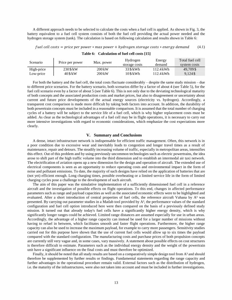
A different approach needs to be selected to calculate the costs when a fuel cell is applied. As shown in Fig. 3, the
battery equivalent to a fuel cell system consists of both the fuel cell providing the actual power needed and the
hydrogen storage system (tank). The calculation is based on following calculation and results shown in Table 6:
𝑓𝑢𝑒𝑙 𝑐𝑒𝑙𝑙 𝑐𝑜𝑠𝑡𝑠 = 𝑝𝑟𝑖𝑐𝑒 𝑝𝑒𝑟 𝑝𝑜𝑤𝑒𝑟 ∗ 𝑚𝑎𝑥 𝑝𝑜𝑤𝑒𝑟 + ℎ𝑦𝑑𝑟𝑜𝑔𝑒𝑛 𝑠𝑡𝑜𝑟𝑎𝑔𝑒 𝑐𝑜𝑠𝑡𝑠 ∗ 𝑒𝑛𝑒𝑟𝑔𝑦 𝑑𝑒𝑚𝑎𝑛𝑑 (4.1)
Table 6: Calculation of fuel cell costs [15]
Scenario Price per power Max. power Hydrogen
storage costs
Energy
demand
Total fuel cell
system costs
High-price 230 $/kW 200 kW 33 $/kWh 112.4 kWh 49,709 $
Low-price 40 $/kW 200 kW 10 $/kWh 112.4 kWh 9,124 $
For both the battery and the fuel cell, the total costs fluctuate considerably – despite the same study mission – due
to different price scenarios. For the battery scenario, both scenarios differ by a factor of about 4 (see Table 5), for the
fuel cell scenario even by a factor of about 5 (see Table 6). This is not only due to the deviating technological maturity
of both concepts and the associated production costs and market prices, but also to disagreement or uncertainty about
current and future price developments of the actual energy sources (electricity vs. hydrogen). Accordingly, a
transparent cost comparison is made more difficult by taking both factors into account. In addition, the durability of
both powertrain concepts must be included in a reasonable comparison. It is assumed that the total number of charging
cycles of a battery will be subject to the service life of a fuel cell, which is why higher replacement costs must be
added. As clear as the technological advantages of a fuel cell may be in flight operations, it is necessary to carry out
more intensive investigations with regard to economic considerations, which emphasize the cost expectations more
clearly.
V. Summary and Conclusions
A dense, intact infrastructure network is indispensable for efficient traffic management. Often, this network is in
a poor condition due to excessive wear and inevitably leads to congestion and longer travel times as a result of
maintenance, repair and detours. The steadily increasing volume of traffic, especially in metropolitan areas, intensifies
this effect. Out of this problem and by using previously uncommon technologies such as electric powertrains, the idea
arose to shift part of the high traffic volume into the third dimension and to establish an intermodal air taxi network.
The electrification of aviation opens up a new dimension for the design and operation of aircraft. The extended use of
electrical components is seen as an opportunity to reduce operating costs and environmental impact in the form of
noise and pollutant emissions. To date, the majority of such designs have relied on the application of batteries that are
(not yet) efficient enough. Long charging times, possible overheating or a limited service life in the form of limited
charging cycles pose a challenge to the development of such aircraft.
The aim of this paper was the simulative implementation of a sufficiently dimensioned fuel cell in a reference
aircraft and the investigation of possible effects on flight operations. To this end, changes in affected performance
parameters such as range and payload capacities as well as the associated economic effects were to be highlighted and
evaluated. After a short introduction of central properties of fuel cells, the reference aircraft Vahana by A³ was
presented. By carrying out parameter studies in a Matlab tool provided by A³, the performance values of the standard
configuration and fuel cell option introduced here were then compared on the basis of a previously defined study
mission. It turned out that already today's fuel cells have a significantly higher energy density, which is why
significantly longer ranges could be achieved. Limited range distances are assumed especially for use in urban areas.
Accordingly, the advantage of a higher range capacity can instead be used for a larger number of missions without
having to refuel in between, which facilitates smooth and faster flight operations. Furthermore, the higher range
capacity can also be used to increase the maximum payload, for example to carry more passengers. Sensitivity studies
carried out for this purpose have shown that the use of current fuel cells would allow up to six times the payload
compared with the standard configuration. The manufacturing costs and purchase prices of both propulsion concepts
are currently still very vague and, in some cases, vary massively. A statement about possible effects on cost structures
is therefore difficult to estimate. Parameters such as the individual energy density and the weight of the powertrain
unit have a significant influence on the final costs and must therefore be optimized.
Finally, it should be noted that all study results are based on a comparatively simple design tool from A³ and should
therefore be supplemented by further results or findings. Fundamental statements regarding the range capacity and
further advantages in the operational procedure remain valid. External factors such as the distribution of hydrogen,
i.e. the maturity of the infrastructures, were also not taken into account and must be included in further investigations.

14
Acknowledgments
This research was funded by the Ministry of Innovation, Higher Education and Research of North Rhine-Westphalia
(Germany) within the interdisciplinary research project “Forschungskolleg ACCESS!”. This support is gratefully
acknowledged.
References
[1] Airbus Ventures. [Online]. Available: https://www.airbus-sv.com/ and https://www.airbusventures.vc/
[Accessed: 8-June-2018]
[2] Benjamin, T., Borup, R., “Fuel Cell Technical Team Roadmap,” U.S. Drive, 2013
[3] Brandon, N.P., Brett, D.J., “Engineering porous materials for fuel cell applications,” Philosophical
Transactions of the Society. Mathematical, Physical and Engineering Sciences. The Royal Society, Vol. 364,
No. 1838, 2006
[4] Carrette, L., Friedrich, K.A., Stimming, U., “Fuel Cells – Fundamentals and Applications,” FUEL CELLS,
Vol. 5, No. 1, 2001
[5] Gonzalez, O., Leo, T.J., Navarro, E., “Fuel Cells: A Real Option for Unmanned Aerial Vehicles Propulsion,”
The Scientific World Journal, Vol. 2014, 2014
[6] Hepperle, M., “Electric Flight – Potential and Limitations,” Energy Efficient Technologies and Concepts of
Operations, 2013
[7] Kadyk, T., Winnefeld, C., Hanke-Rauschenbach, R., Krewer, U., “Analysis and Design of Fuel Cell Systems
for Aviation,” Energies, Vol. 11, No.2, 2018
[8] Kanawka, K., “Fuel Cells for Mobile Applications,” Journal of KONES Powertrain and Transport, Vol. 19,
No. 4, 2012
[9] Krawczyk, J.M., Mazur, A.M., Sasin, T., Stoklosa, A.W., “Fuel Cells as Alternative Power for Unmanned
Aircraft Systems – Current Situation and Development Trends,” Transaction of the Institute of Aviation,
Vol. 237, No. 4, 2014
[10] Kreimeier, M., “Evaluation of On-Demand Air Mobility Concepts with Utilization of Electric Powered Small
Aircraft,” Ph.D. Thesis, RWTH Aachen University, 2018
[11] Kurzweil, P., „Brennstoffzellentechnologie. Grundlagen, Komponenten, Systeme, Anwendungen,“ 2nd Ed.
Springer, Berlin, 2013. ISBN: 978-3-658-00084-4
[12] Larminie, J., Dicks, A., “Fuel Cells Systems Explained,” 2nd Ed. Wiley, West Sussex, 2003,
ISBN: 978-0-470-84857-9
[13] Luo, X., Wang, J., Dooner, M., Clarke, J., “Overview of current development in electrical energy storage
technologies and the application potential in power system operation,” Applied Energy, Vol. 137, No. 1, 2015
[14] Roland Berger, “Think:Act. Aircraft Electrical Propulsion – The Next Chapter of Aviation?”, 2017
[15] Satyapal, S., “Hydrogen and Fuel Cells Overview,” U.S. Department of Energy, Fuel Cell Technologies
Office, DLA Worldwide Energy Conference, National Harbor, MD, USA, April 12th, 2017
[16] Sisco, J., Robinson, P., Osenar, P., “New Fuel Cell Technologies Extend Missions for Vertical Take-Off and
Landing Unmanned Aerial Vehicles,” 2017
[17] Vahana Aero, [Online]. Available: http://www.vahana.aero [Accessed: 25-Octover-2018]
[18] Vertical Flight Society, Electric VTOL News, [Online]. Available: http://evtol.news/aircraft/a3-by-airbus/
[Accessed: 25-October-2018]
[19] Warshey, M., Prokopius, P.R., “The Fuel Cell in Space: Yesterday, Today and Tomorrow, Lewis Research
Center,” NASA Technical Memorandum 102366, London, 1989
[20] Westenberger, A., „Wasserstoff und Brennstoffzelle – mobile Anwendung in der Luftfahrt,“ In: Wasserstoff
und Brennstoffzelle. Technologie und Marktperspektiven. 2nd Ed. Springer, Berlin, 2017.
ISBN: 978-3-662-53359-8
[21] Winnefeld, C., Kadyk, T., Bensmann, B., Krewer, U., Hanke-Rauschenbach, R., „Modelling and Designing
Cryogenic Hydrogen Tanks for Future Aircraft Aplications,“ Energies, Vol. 11, No. 1, 2018
[22] Wishart, J., “Fuel Cells vs Batteries. In the Automotive Sector,” 2014
[23] Yoshida, T., Kojima, K., “Toyota MIRAI Fuel Cell Vehicle and Progress Toward a Future Hydrogen
Society,” The Electrochemical Society, Vol. 24, No. 2, 2015