assessment and restoration of a masonry dome in the ...€¦ · assessment and restoration of a...
TRANSCRIPT

Assessment and restoration of a masonry dome in the cathedral of Tortosa enclosure
J. Lluís i Ginovart, A. Costa & G. Fortuny Predepartamental Unit of Architecture, Rovira i Virgili University (Reus), Spain
Abstract
In April of 2011, one of the masonry domes of the cathedral of Tortosa enclosure (Catalunya, near Barcelona) suddenly broke. This paper presents the restoration process of this XVIII century dome, exposing the evolution of the rupture and its causes, the analysis of the cracking process and the numerical approaches developed to determine the restoration techniques. After an initial constructive assessment, the equilibrium conditions of the structure are analysed. Traditional graphical methods are used complementary to a 3D survey by finite elements (FEM), using the free software Salome-Meca 6.3. Through the models developed, it is possible to relate the tensional states and the deformations of the shell with the real breaking process of the dome. The assessment concludes that the dome does not break because of a failure of the material by tensional problems, but does because of an asymmetric load which causes the formation of collapse joints. This load was a consequence of the breaking of a beam which held the combined load of the roof and part of the lantern. The intervention consisted of restoring the shell of the dome with traditional techniques, “guix i estopa”, and also reinforcing the bearing capacity of the structure to support the weight of the big lantern and also the roof. Keywords: FEM analysis, heritage preservation, masonry domes, oval domes, structural restoration.
1 Introduction
The gothic cathedral of Tortosa was raised during the fourteenth century, and presents different additions built through time [1]. The ‘Sacristia Nova’ is one of them, built in the late eighteenth century by Antoni Ferrer. There is a room of
Structural Studies, Repairs and Maintenance of Heritage Architecture XIII 391
www.witpress.com, ISSN 1743-3509 (on-line) WIT Transactions on The Built Environment, Vol 131, © 2013 WIT Press
doi:10.2495/STR130331

transition between the Sacristia and the gothic apse, covered by an oval dome built in 1784 by Josep Melet. Oval or elliptical domes are a characteristic baroque structural typology which appears in the mid-sixteenth century, with widespread use during the seventeenth century during the ‘Contrarreforma’ of the Catholic Church [2]. Based on previous works, Heyman [3] sets the principles to assess the stability of domes, and more recently Huerta [4] analyzed history and mechanical principles of this specific kind of dome. Other authors have undertaken studies around these typologies, as the assessment of the great oval dome of Vicoforte Sanctuary by FEM [5, 6], or the work by Lau based on Wolfe’s method to assess domes with very thin shells [7, 8]. The restoration process mainly consisted of the following stages of work: - Structural prevention: to avoid risks during works, underpinning the dome and
lightening the structure by dismounting the lantern and the roof. - Assessment of the structure: which includes visual inspection,
photogrammetric survey and numerical approaches. - Restoration of the dome: restoring the shell and reinforcing its bearing
capacity.
Figure 1: General plant of the cathedral and section of the Sacristia Nova and
the gothic apse.
2 Description of the case
2.1 Geometry
The following measures are deduced from the survey conducted during restoration in May 2011. The impost of the dome is 833 cm high above the floor, covering a room measuring 460x371 cm. The oval plant layout is built from two perpendicular axes of 455 and 365 cm, and the shell is an ovoid of revolution with internal radius about 160–170 cm. There is a quasi-oval oculus situated at about 177–186 cm from the impost. This variable height is caused by the geometrical intersection between the cylindrical projection of the oculus and the curved shell. There is the lantern over
392 Structural Studies, Repairs and Maintenance of Heritage Architecture XIII
www.witpress.com, ISSN 1743-3509 (on-line) WIT Transactions on The Built Environment, Vol 131, © 2013 WIT Press
it, which measures 385 cm in height. It is covered with a little spherical dome with an internal radius of about 146 cm.
2.2 Construction system and materials
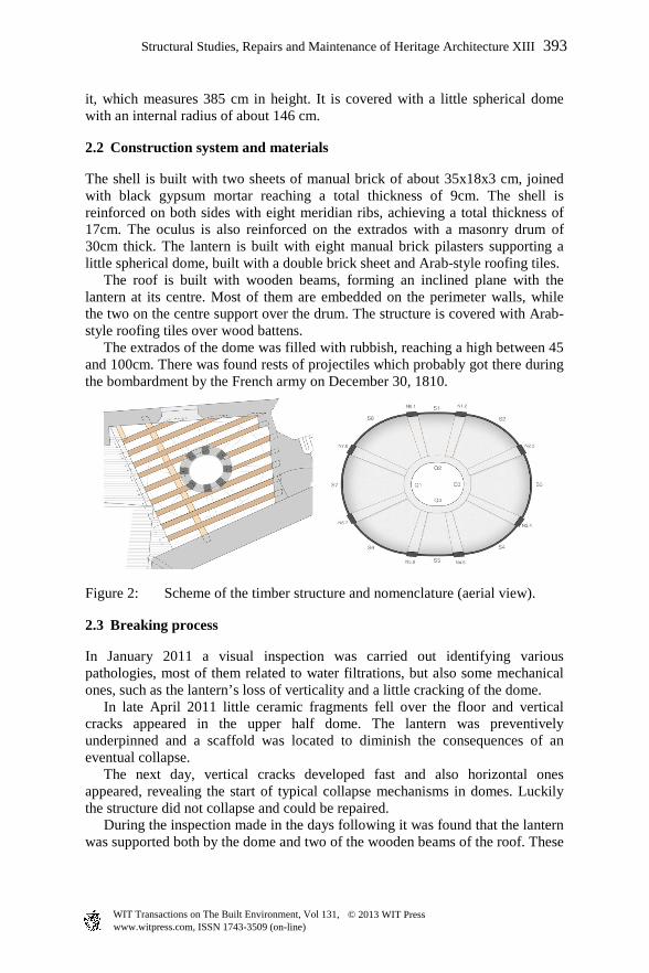
The shell is built with two sheets of manual brick of about 35x18x3 cm, joined with black gypsum mortar reaching a total thickness of 9cm. The shell is reinforced on both sides with eight meridian ribs, achieving a total thickness of 17cm. The oculus is also reinforced on the extrados with a masonry drum of 30cm thick. The lantern is built with eight manual brick pilasters supporting a little spherical dome, built with a double brick sheet and Arab-style roofing tiles. The roof is built with wooden beams, forming an inclined plane with the lantern at its centre. Most of them are embedded on the perimeter walls, while the two on the centre support over the drum. The structure is covered with Arab-style roofing tiles over wood battens. The extrados of the dome was filled with rubbish, reaching a high between 45 and 100cm. There was found rests of projectiles which probably got there during the bombardment by the French army on December 30, 1810.
Figure 2: Scheme of the timber structure and nomenclature (aerial view).
2.3 Breaking process
In January 2011 a visual inspection was carried out identifying various pathologies, most of them related to water filtrations, but also some mechanical ones, such as the lantern’s loss of verticality and a little cracking of the dome. In late April 2011 little ceramic fragments fell over the floor and vertical cracks appeared in the upper half dome. The lantern was preventively underpinned and a scaffold was located to diminish the consequences of an eventual collapse. The next day, vertical cracks developed fast and also horizontal ones appeared, revealing the start of typical collapse mechanisms in domes. Luckily the structure did not collapse and could be repaired. During the inspection made in the days following it was found that the lantern was supported both by the dome and two of the wooden beams of the roof. These
Structural Studies, Repairs and Maintenance of Heritage Architecture XIII 393
www.witpress.com, ISSN 1743-3509 (on-line) WIT Transactions on The Built Environment, Vol 131, © 2013 WIT Press

had been attacked by termites, loosening the resistant section until it yielded under the weight of the lantern. Thus, it is deduced that the displacements of the dome were caused by the application of an asymmetric new load on the oculus. Cracking was the consequence of the accommodation process of the masonry to the new solicitations. Meridian cracks appeared at the first place, followed by the radial ones which could cause the collapse of the structure. Finally, the dome did not fall because the cinematic process underpinning the lantern was stopped. Also, the rubbish of the extrados prevented the formation of the lower meridian cracks, which should have led to the collapse of the dome.
Figure 3: Breaking process of the dome.
2.4 Photogrammetric survey
A photogrammetric survey is performed in order to know the dome’s deformed geometry, obtaining a high precision model. It is based on 287 points to define the ribs geometry, and 38.297 points to determine the shell. After, a second non-deformed model is carried out taking as reference the least deformed shapes of the first one.
Figure 4: Photogrammetric survey and comparison of displacements.
394 Structural Studies, Repairs and Maintenance of Heritage Architecture XIII
www.witpress.com, ISSN 1743-3509 (on-line) WIT Transactions on The Built Environment, Vol 131, © 2013 WIT Press

An assessment is made of the deformations by the comparison of the two models. It revealed that the most deformed shell section was S6, moving down 8cm in the oculus. Also, the shell sections S3, S4 and S6 deformed similarly, but with lower values. The rest of the shell sections presented a horizontal displacement of the central zone, followed by the lowering of the upper part. Section S5 was the most deformed, with a displacement of about 6cm. Concerning the ribs, the most deformed ones were N3.4, N4.5, N5.6 and N6.7. All of them moved the same way: lowering of the upper edge (up to 6 cm) and horizontal displacement to the outside of up to 13cm (N5.6). So, the section S6 and the rib N5.6 were the most affected parts. They are on the same side of where the beam failed and also where an opening was found to access the extrados. A movement on the buttressing system is discarded considering the nature of the damage and the inexistence of variations on the neighbouring structures. In order to select the most appropriate techniques of restoration it is necessary to know the bearing capacity of the dome to support loads. So, several numerical approaches are performed.
3 Structural assessment
The dome is built with the constructive technique known in Spain as ‘volta tabicada’ or also ‘volta catalana’ [9]. It is a kind of masonry dome built with very thin sheets of brick and gypsum mortar. As a masonry dome, it transmits thrusts and has very low tensional resistance. In this case, we found an unusual proportion between lantern and dome weights. The lantern used to be 5% or 10% of the total weight, but here it represents 65%. Thus, the significant role of the wood beams in the stability is deduced from this value. The characterization of loads are based on the following data obtained: specific weight of masonry: 1.8x10⁻⁵ N/mm3; roof load: 1.5x10⁻³ N/mm2; lantern weight: 70 kN. Moreover, the bricks were essayed in a laboratory to establish their compressive strength, obtaining a medium value of 10.1 N/mm2.
3.1 Thrust lines
The assessment is made on the theoretical framework of limit analysis, which considers masonry with no tensional resistance, infinite compression strength and impossibility of sliding parts. The slice technique is used to assess the capacity of the dome under gravitational loads [10, 11]. The display of the dome geometry is based on two axial symmetry axes. Thus, the assessment is made for the two characteristic sections of the shell, corresponding with the main axes, and also for the two ribs between them. Thus, equilibrium conditions are assessed for the sections S5 and S7 and ribs N5.6 and N6.7.
Structural Studies, Repairs and Maintenance of Heritage Architecture XIII 395
www.witpress.com, ISSN 1743-3509 (on-line) WIT Transactions on The Built Environment, Vol 131, © 2013 WIT Press
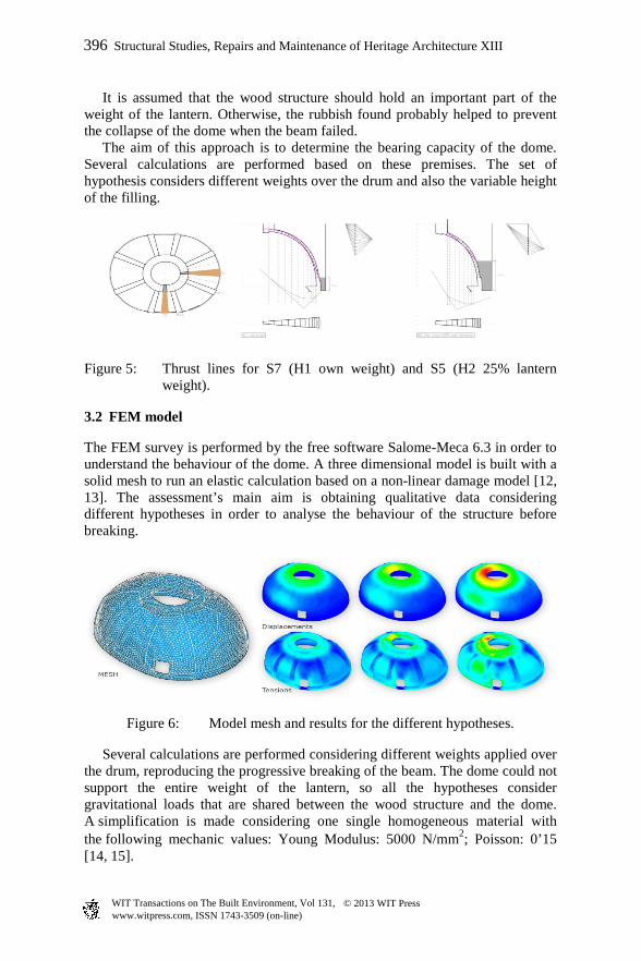
It is assumed that the wood structure should hold an important part of the weight of the lantern. Otherwise, the rubbish found probably helped to prevent the collapse of the dome when the beam failed. The aim of this approach is to determine the bearing capacity of the dome. Several calculations are performed based on these premises. The set of hypothesis considers different weights over the drum and also the variable height of the filling.
Figure 5: Thrust lines for S7 (H1 own weight) and S5 (H2 25% lantern weight).
3.2 FEM model
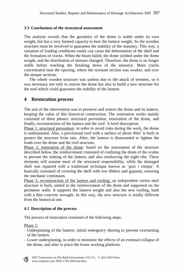
The FEM survey is performed by the free software Salome-Meca 6.3 in order to understand the behaviour of the dome. A three dimensional model is built with a solid mesh to run an elastic calculation based on a non-linear damage model [12, 13]. The assessment’s main aim is obtaining qualitative data considering different hypotheses in order to analyse the behaviour of the structure before breaking.
Figure 6: Model mesh and results for the different hypotheses.
Several calculations are performed considering different weights applied over the drum, reproducing the progressive breaking of the beam. The dome could not support the entire weight of the lantern, so all the hypotheses consider gravitational loads that are shared between the wood structure and the dome. A simplification is made considering one single homogeneous material with the following mechanic values: Young Modulus: 5000 N/mm2; Poisson: 0’15 [14, 15].
396 Structural Studies, Repairs and Maintenance of Heritage Architecture XIII
www.witpress.com, ISSN 1743-3509 (on-line) WIT Transactions on The Built Environment, Vol 131, © 2013 WIT Press
3.3 Conclusions of the structural assessment
The analysis reveals that the geometry of the dome is stable under its own weight, but has a very limited capacity to bear the lantern weight. So the wooden structure must be involved to guarantee the stability of the masonry. This way, a variation of loading conditions easily can cause the deformation of the shell and the formation of cracks. When the beam failed, the dome yielded under the dome weight, and the distribution of stresses changed. Therefore, the dome is no longer stable before reaching the breaking stress of the masonry. Main cracks concentrated near the opening, where the resistant section was weaker, and over the steeper sections. The whole wooden structure was useless due to the attack of termites, so it was necessary not only to restore the dome but also to build a new structure for the roof which could guarantee the stability of the lantern.
4 Restoration process
The aim of the intervention was to preserve and restore the dome and its lantern, keeping the value of this historical construction. The restoration works mainly consisted of three phases: structural prevention, restoration of the dome, and finally, reconstruction of the lantern and the roof. A brief description: Phase 1, structural prevention: in order to avoid risks during the work, the dome is underpinned. Also, a provisional roof with a surface of about 40m2 is built to protect the structure from rain. After, the lantern is dismounted to lighten the loads over the dome and the roof structure. Phase 2, restoration of the dome: based on the assessment of the structure described below, the reinforcement consisted of confining the drum of the oculus to prevent the sinking of the lantern, and also reinforcing the eight ribs. These elements will assume most of the structural responsibility, while the damaged shell was repaired with a traditional technique known as ‘guix i estopa’. It basically consisted of covering the shell with tow fibbers and gypsum, restoring the mechanic continuum. Phase 3, reconstruction of the lantern and roofing: an independent corten steel structure is built, united to the reinforcement of the drum and supported on the perimeter walls. It supports the lantern weight and also the new roofing, built with a thin concrete wrought. In this way, the new structure is totally different from the historical one.
4.1 Description of the process
The process of restoration consisted of the following steps:
Phase 1: - Underpinning of the lantern: initial emergency shoring to prevent overturning
of the lantern. - Lower underpinning, in order to minimize the effects of an eventual collapse of
the dome, and after to place the lower working platform.
Structural Studies, Repairs and Maintenance of Heritage Architecture XIII 397
www.witpress.com, ISSN 1743-3509 (on-line) WIT Transactions on The Built Environment, Vol 131, © 2013 WIT Press

- Situation of the upper working platform over the roof, supported by the perimeter walls, and provisional covering with a light metallic structure to protect the historical elements and prevent rainwater seepage.
- Dismounting of the lantern and the roof. Extraction of material to lighten the structure. Recoverable parts of the lantern are marked and stored in order to be able to reconstruct it.
Figure 7: Underpinning of the lantern.
Figure 8: Securing of the oculus with a steel ring.
Phase 2: - Securing of the oculus with a corten steel ring, which after would translate the
efforts to the walls through nine steel sections. - Reinforcement of the ribs by the situation of a laminated steel profile on each
one, fixed in the intrados by stainless steel connectors. - Reparation of shell cracks with guix i estopa: the entire extrados are covered
with this technique, and also the cracks on the intrados. Several stainless steel connectors are used to guarantee the fixation. A second layer of gypsum is made in both faces to give a smoother finish to the surfaces.
398 Structural Studies, Repairs and Maintenance of Heritage Architecture XIII
www.witpress.com, ISSN 1743-3509 (on-line) WIT Transactions on The Built Environment, Vol 131, © 2013 WIT Press
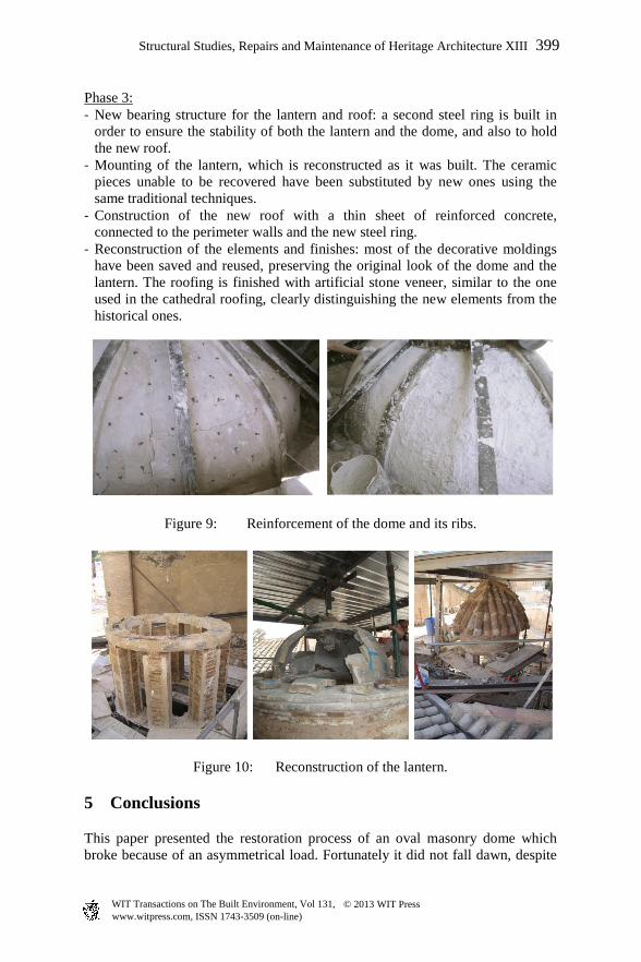
Phase 3: - New bearing structure for the lantern and roof: a second steel ring is built in
order to ensure the stability of both the lantern and the dome, and also to hold the new roof.
- Mounting of the lantern, which is reconstructed as it was built. The ceramic pieces unable to be recovered have been substituted by new ones using the same traditional techniques.
- Construction of the new roof with a thin sheet of reinforced concrete, connected to the perimeter walls and the new steel ring.
- Reconstruction of the elements and finishes: most of the decorative moldings have been saved and reused, preserving the original look of the dome and the lantern. The roofing is finished with artificial stone veneer, similar to the one used in the cathedral roofing, clearly distinguishing the new elements from the historical ones.
Figure 9: Reinforcement of the dome and its ribs.
Figure 10: Reconstruction of the lantern.
5 Conclusions
This paper presented the restoration process of an oval masonry dome which broke because of an asymmetrical load. Fortunately it did not fall dawn, despite
Structural Studies, Repairs and Maintenance of Heritage Architecture XIII 399
www.witpress.com, ISSN 1743-3509 (on-line) WIT Transactions on The Built Environment, Vol 131, © 2013 WIT Press

the great damage it presented. The fast underpinning of the structure and also the existence of rubbish filling part of the extrados prevented the collapse of the dome. The studies performed revealed that the dome itself was not enough to hold the lantern on top, collaboration of other resistant elements being necessary. Thus, it has been possible to preserve the original dome by introducing new structural elements which ensure the stability. Moreover, it has been possible to restore it with traditional techniques, keeping the historical value of this XVIIIth century masonry dome.
Figure 11: Bottom view of the restored dome.
References
[1] Almuni, V. and Lluís, J., Sancta Maria Dertosae. Catedral de Tortosa. Guia histórica i descriptiva, Capítol Catedral de Tortosa – Bisbat de Tortosa: Tortosa, 2000.
[2] Stefano, B., The architecture and mechanics of elliptical Domes. Proc. of the 3rd Int. Cong. On Construction History, Cottbus, ed. Neunplus1: Berlin, pp. 83-91, 2009.
[3] Heyman, J., The stone skeleton: structural engineering of masonry architecture. Cambridge University Press: Cambridge, 27-47, 1995.
[4] Huerta, S., Oval Domes: History, Geometry and Mechanics. Nexus Network Journal, Vol. 9 (2), pp. 211-247, 2007.
400 Structural Studies, Repairs and Maintenance of Heritage Architecture XIII
www.witpress.com, ISSN 1743-3509 (on-line) WIT Transactions on The Built Environment, Vol 131, © 2013 WIT Press
[5] Aoki, T., Chiorino, M.A., Roccati, R., Structural characteristics of the elliptical masonry dome of the sanctuary of Vicoforte. Proc. of the 1stInt. Cong. on Construction History, Madrid, ed. S. Huerta, I. Juan de Herrera: Madrid, pp. 203-212, 2003.
[6] Chiorino, M.A., Spadafora, A., Calderini, C., Lagomarsino, S. Modeling Strategies for the World’s Largest Elliptical dome at Vicoforte. International Journal of Architectural Heritage: Conservation, Analysis, and Restoration, 2(3), pp. 274-303, 2008.
[7] Lau, W., Equilibrium analysis of masonry domes, Master Thesis of Science in Building Technology, Massachusetts Institute of Technology, 2006
[8] Wolfe, W.S., Graphical Analysis: A textbook on graphic statics. McGraw Hill Book Co.: New York, 1921.
[9] Moya, L., Bóvedas tabicadas. Dirección General de la Vivienda, la Arquitectura y el Urbanismo, 2ª ed. Madrid, Ministerio de Fomento. Centro de Publicaciones, Madrid, 2000.
[10] Huerta, S., Mechanics of masonry vaults: the equilibrium approach. Proc. of the 1stInt. Cong. On Structural Analysis of Historical constructions, Guimaraes, eds. P.B. Lourenço and P. Roca, pp. 47-70, 2001.
[11] Huerta S. and López, G., Estudios estructurales previos a la restauración de la iglesia de Santo Tomás de Villanueva (“La Mantería”) de Zaragoza, ed. Instituto de Patrimonio Histórico Español, Madrid, 2001.
[12] Simó, J.C. and Ju, J.W., Strain- and stress-based continuum damage models, I. Formulation, Int. J. Solids Struct. 23, pp. 821–840, 1987
[13] Pelà, L., Cervera, M., and Roca, P. Continuum damage model for orthotropic materials: Application to masonry. Comput. Methods Appl. Mech. Engrg. 200, pp. 917–930, 2011 .
[14] Lourenço, P.B., Computational Strategies for Masonry Structures, Delft University Press. Delft, 1996.
[15] Alonso, A., Gomis, J., Moreno, J. and Llopis, V., Arquitectura religiosa: análisis constructivo y estructural. Actas del Séptimo Congreso Nacional de Historia de la Construcción, Santiago de Compostela, ed. S. Huerta, Instituto Juan Herrera: Madrid, pp. 55-64, 2011.
Structural Studies, Repairs and Maintenance of Heritage Architecture XIII 401
www.witpress.com, ISSN 1743-3509 (on-line) WIT Transactions on The Built Environment, Vol 131, © 2013 WIT Press