assessing mechanical damage using … offer spirall/mds. 6 value of multiple datasets mfl w/idod...
TRANSCRIPT

www.tdwilliamson.com
® Registered trademarks of T.D. Williamson, Inc. in the United States and in foreign countries. © Copyright 2012
ASSESSING MECHANICAL DAMAGE
USING MULTIPLE DATA SETS IN ILIAbel Lopes
Market Development Manager EH
14th November 2012

2Source: 8th Report of the European Gas Pipeline Incident Data Group
Failure Causes

3
Failure Causes
Source: Performance of European cross-country oil pipelines Statistical summary of reported spillages in 2010 and since 1971
Prepared by the CONCAWE Oil Pipelines Management Group’s Special Task Force on oil pipeline spillages (OP/STF-1)

4
Introduction
Technology Limitations

5
TDW Offer
SPIRALL/MDS

6
Value of Multiple Datasets
MFL w/IDOD
• Volumetric Anomalies
• Mill Anomalies
• Extra Metal
• Internal/External Classification
• Dents
DEF
• Ovalities
• Dents
• Misalignments
• Other bore changes
Residual / Low Field Magnetization
• Permiability Anomalies – Hard spots
• Mechanical Stress
• Pipe Characteristic Changes
SMFL
• Gouging
• Narrow Axial Corrosion
• Selective Seam Corrosion
• Planar / Crack-like Seam Anomalies
• Volumetric Anomalies (pipe body or seam)
• Mill Anomalies Dent with
residual
stress
Dent with Volumetric
Metal Loss
Dents with Metal Loss
Pipe Characteristic Changes
Gouging/ML without dent
Planar versus Volumetric
Axially oriented Anomalies
Metal Loss in Seamless Pipe
Metal Loss crossing Girth Welds

7
Axial MFL

80 1 2 3 4 5 6 7 8
0
1
2
3
4
5
6
7
8
Normalized Defect Length, L/A
Norm
aliz
ed D
efe
ct
Wid
th,
W/A
Axial Slotting
Axial GroovingPitting
General
Pinhole
Circum
fere
ntial S
lott
ing
Circum
fere
ntial G
roovin
g
Axial MFL
Axial MFL

9
SpirALL™ MFL Technology

10
SpirALL™ MFL Technology
0 1 2 3 4 5 6 7 80
1
2
3
4
5
6
7
8
Normalized Defect Length, L/A
Norm
aliz
ed D
efe
ct
Wid
th,
W/A
Axial Slotting
Axial GroovingPitting
General
Pinhole
Circum
fere
ntial S
lott
ing
Circum
fere
ntial G
roovin
g
SpirALL™ MFL

11
• Magnetizer• SMFL concept enables Multiple DataSet platform
SpirALL™ MFL Technology

12
Axial MFL + SMFL

130 1 2 3 4 5 6 7 8
0
1
2
3
4
5
6
7
8
Normalized Defect Length, L/A
Norm
aliz
ed D
efe
ct
Wid
th,
W/A
Axial Slotting
Axial GroovingPitting
General
Pinhole
Circum
fere
ntial S
lott
ing
Circum
fere
ntial G
roovin
g
Axial MFL
SpirALL™ MFL
Overlap = Enhanced
Characterization
Axial MFL + SMFL

14
• 16-inch inspection tool runs indicated that SpirALL™ MFL technology
successfully identifies narrow axial defects that normally would not be
reported by axial MFL alone.
SMFLMFL
Axial MFL + SMFL

15
• By combining axial MFL with SpirALL™ MFL in the same run, it
becomes possible to identify the anomaly as a metal loss feature that
happens to be in the seam weld instead of a crack-like feature in the
seam
Axial MFL + SMFL

16
The Multiple DataSet Advantage
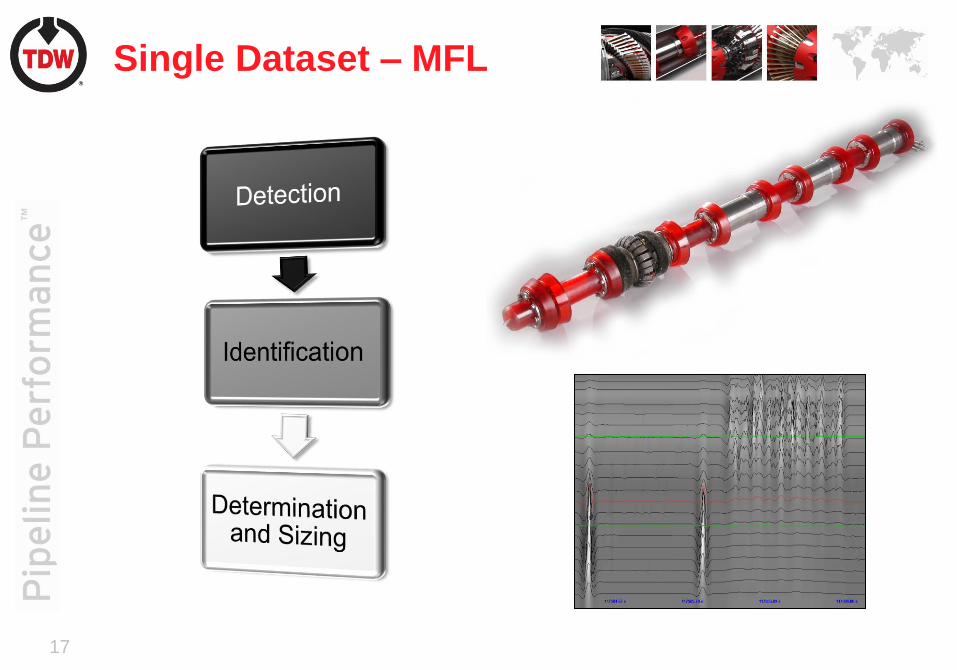
17
Single Dataset – MFL

18
Multiple Datasets

19
MFL SMFL
Characterization
Metal Loss crossing and within a girth weld

20
Characterization
• Mechanical Damage
MFL data – not able to capture
anomaly extent
SMFL data - reported accurately as
continuous anomalies

21
Characterization
• Axial (Planar) Defects

22
Characterization
• Seam Weld Defects
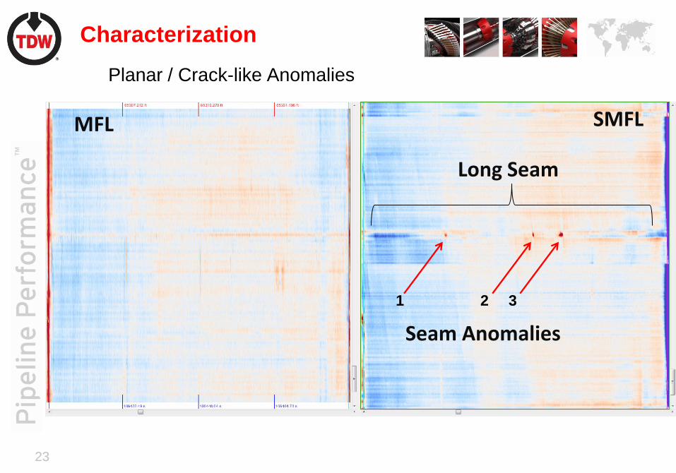
23
MFL SMFL
Seam Anomalies
Long Seam
1 2 3
Planar / Crack-like Anomalies
Characterization

24
Anomaly 1, 2 and 3 (left to right): zoomed in SMFL screenshot with dig photo
# Descr. ILI % Field % ILI
Length
(mm)
Field
Length
(mm)
ILI Width
(mm)
Field
Width
(mm)
1 Planar 19 16 109 140 1.3 Linear
2 Planar 29 14 61 73 1.8 Linear
3 Planar 15 16 188 198 2.0 Linear
Planar / Crack-like Anomalies
Characterization

25
Residual and Low Field MFL

26
Residual and Low Field
B
Time
BMFL max saturation
Har
dnes
s
1
2
• Two different steel lattices will produce two different
residual measurements (1,2)
• This happens with hard spots, heat affected zones, and
stress.
27
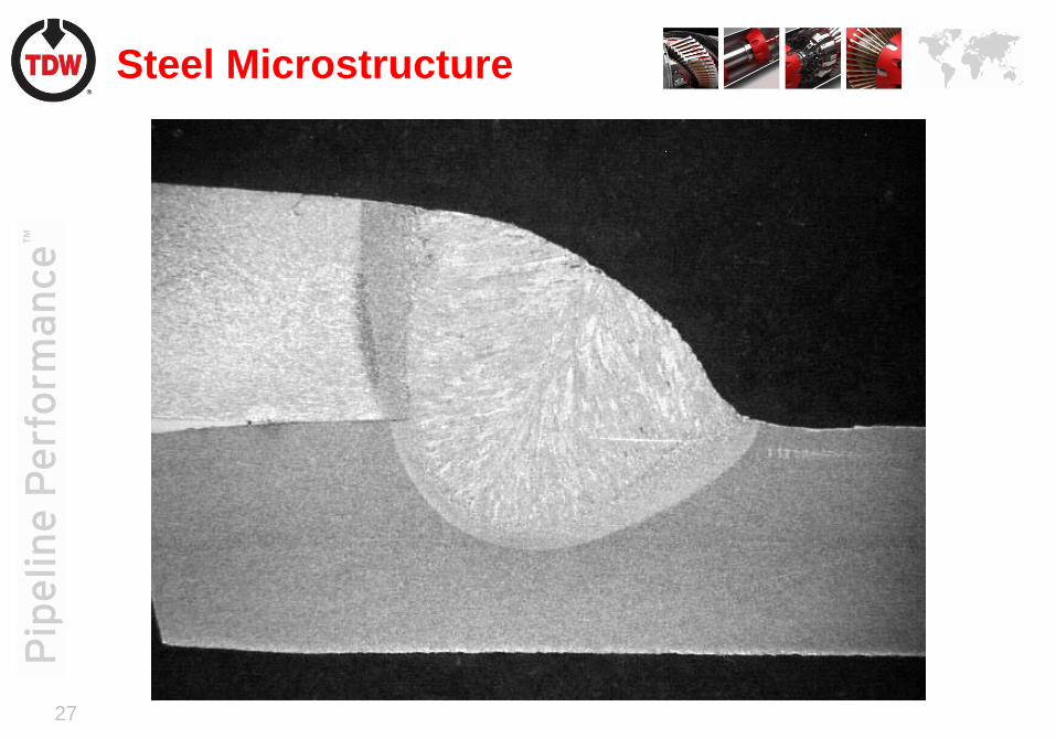
Steel Microstructure

28
Steel Microstructure
• Low Carbon

29
Steel Microstructure (High-carbon)
• High Carbon

30
Hard Spot / Crack
Analysis of High-Collapse Grade P110 Coupling Failures - A Case Study by Stork Materials

31
Mechanical Damage

32
Re-rounded versus Cycled Dents
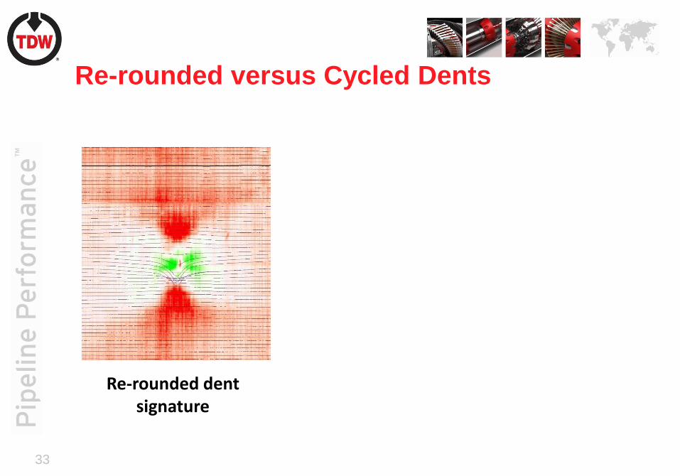
33
Re-rounded versus Cycled Dents
Re-rounded dent signature
Cycled dent signature,notice the strong
“halo” effect

34
• ASME B31.8 provides non-mandatory Appendix R which outlines methods
for estimating strains in a dent
• Enhancements to the ASME formulas, suggested by recent industry
research, have been incorporated
• Computations can be carried out using high resolution deformation data
• Local dent strain can be estimated by analyzing the deformed shape
• The Battelle prioritization model is then supplemented:
• If a dent exhibits strain > 6% then considered higher priority
Strain Calculations

35
• Mechanical Damage
• Utilization of Battelle Mechanical Damage
Prioritization Model developed in 2002
• PRCI L52084
• Supplemented with:
• Dent Strain
• SMFL for gouging and metal loss
• Proximity to girth and seam weld
D e c o u p le d
S ig n a l? N o
N o
N o
Y e s
Y e s
Y e s N o
N o N o
Y e s
Y e s
N o
N o
Y e s
Y e s
N o
A p p ly
D e c o u p lin g
H ig h
M a g n e t iz a t io n
D a ta
L o w
M a g n e t iz a t io n
D a ta
Y e s N o
Y e s R e s id u a l
D e n t?
G o u g e
S ig n a l?
R e ro u n d in g
H a lo ?
Y e s
N o Y e s
M e ta l
L o s s ?
C y c l ic
L o a d s ?
P lo w in g
S ig n a l?
R e s id u a l
D e n t? N o
M e ta l
L o s s ?
T o p o f
P ip e ?
R e s id u a l
D e n t?
R e s id u a l
D e n t?
L o w
P r io r i ty
M o d e ra te
P r io r i ty
M o d -H ig h
P r io r i ty
M o d -L o w
P r io r i ty
H ig h
P r io r i ty
Y e s
Prioritization

36
Prioritization

37
Case Study

38
Conclusion
• Individual technologies have limitations when used independently as
defined by NACE SP0102-2010
• Multiple Datasets (DEF+SMFL+MFL+RES):
• Overcome limitations of individual technologies
• Provide clarity of axial anomalies, and because of combination of
Axial MFL with SpirALL,
• More effectively detects and characterizes crack-like and metal loss
anomalies whether seam or pipe body
• Accurately detects and characterizes 3rd party damage for
prioritization
• Will ultimately translates into greater accuracy of results
• Proven to eliminate unnecessary seam anomaly excavations

39
Thank You!Trusted Performance / Innovative Solutions