assembly manual for the new two tinned tunas - ez build kit
TRANSCRIPT

Assembly manual for the new
Two Tinned Tunas - EZ Build Kit

You should inventory and organize all your parts before starting to build your kit. Any shortages can be identified quickly and resolved. Having all the
parts sorted and ready to go allows for faster assembly.
R1 = 4.7K C1 = .01UF L1 = 22UH Q1 = 2N2222AR2 = 47K C2 = 100PF L2 = 10UH Q2 = 2N2222AR3 = 220 C3 = .01UF L3 = 1UH Q3 = 2N3906R4 = 100 C4 = 220PF L4 = 1UH J1 = RCA R5 = 1K C5 = .1UF J2 = RCAR6 = 22K C6 = .1UF J3 = 1/8” STEREOR7 = 6.8 C7 = .1UF CRYSTAL 1 = 7.040R8 = 2.2K C8 = 470PF CRYSTSL 2 = 7.030R9 = 10K C9 = unused X1 = 8 PIN SIPR10 = 1K C10 = 1000PF P1 = 100 OHM TRIMMER
C11 = 120PF BOLT = 1/8” X 32 X 1 ½”C12 = 470PF NUT = 1/8” X 32C13 = .1UFC14 = .1UFC15 = 22UF

Familiarize yourself with the schematic.
Look over the board and check the general locations of the parts…

And now we can start soldering in the parts…..
R1 = 4.7K ohms = yellow violet red
R2 = 47K ohms = yellow violet orange

R3 = 220 ohms = red red brown
R4 = 100 ohms = brown black brown

R5 = 1K ohms = brown black red
To speed construction, you can insert several parts and bend the leads apart slightly on the bottom side of the board. Flip the board over and place it on
the lip of the can. The can holds the board and the parts should stay in place. Now you can solder them all in, clip off the excess leads and continue
on…

R6 = 22K ohms = red red orange
R7 = 6.8 ohms = blue gray silver

R8 = 2.2K ohms = red red red
R9 = 10K ohms = brown black red
R10 = 1K ohms = brown black red

That is it for the resistors. The technique we are using here is to solder in all the parts by type. Resistors, socket pins, capacitors, inductors and
connectors are soldered onto the board in sequence.
Now we will proceed with construction by installing the socket pins used for the crystal socket and final transistor. The socket pins are cut from a single 8 pin SIP (Single Inline Pin) socket. The crystal socket requires a single 3-pin socket and transistor Q2 requires 3 single pins, leaving 2 unused pins.
Cut the 3-pin crystal socket from the SIP socket strip.

Insert the leads of any of the capacitors into the 3-pin socket in order to have a ‘handle’ to hold the socket while soldering. DO NOT SOLDER THEM!,
Just insert the capacitor leads into the socket as shown above.
Setting the inverted board down onto the socket and use the ‘cap handle’ like a kick stand. Solder a single end pin, then examine the socket to see that it is standing square on the board. If not, retouch the solder while attempting to align the socket properly. Once you are satisfied that the socket is sitting nice, solder the other 2 pins and unplug the capacitor
‘handle’.

The crystal socket should look like this….
Now cut 3 single pins from the remaining 5 pin SIP. Stick 2 pins to the cap again making a soldering ‘handle’. DO NOT SOLDER
THEM! Just insert the capacitor leads into the sockets.

Rest the soldering iron across the top of the can. Please be careful that you don’t burn yourself on this step. We are using the can as a third hand for
holding the soldering iron. The first hand holds the board and pins using the handle while the second hand holds the solder.
You can’t see it from this view; but, my left hand is holding the board with the index finger keeping the ‘handle’ with socket pins pressed firmly against
the board. If my right hand wasn’t holding the camera, you would see the solder coming in from the right… Sneak the board into position under the tip
of the iron and add the solder. Solder the 3rd socket pin onto the board using the same method.

The Q1 socket pins should look like this.
Now we start on the capacitors.C1 = .01uf = 103

C2 = 100pf = 101 which is the small axial capacitor
C3 = .01uf = 103

C4 = 220pf = 221
C5 = .1uf = 104

Again, you can batch insert several capacitors and solder them all in at the same time. Spreading the leads slightly when they exit the bottom of the
board will keep them in place when you flip over the board to solder. Setting the board on the lip of the can will provide a nice base for the board while
soldering. No vice is needed to assemble the board!
C6 = .1uf = 104

C7 = .1uf = 104
C8 = 470pf = 471

C9 is unused
C10 = 1000pf = 102

C11 = 120pf = 121
C12 = 470pf = 471

C13 = .1uf = 104
C14 = .1uf = 104

C15 = 22uf = 22UFC15 is an electrolytic capacitor which is polarity sensitive. Make sure that the negative lead, which has the black stripe, is towards the center of the
board.
OK! Now we can install the chokes. The chokes, or inductors, that are included in the kit look similar to ¼ watt resistors. They are a little ‘tubbier’ and should be fairly easy to spot amongst the resistors. They have the same
striped marking system.

oL1 = 22uH = red red black (small tubby)
L2 = 10uH = brown black black (large tubby)
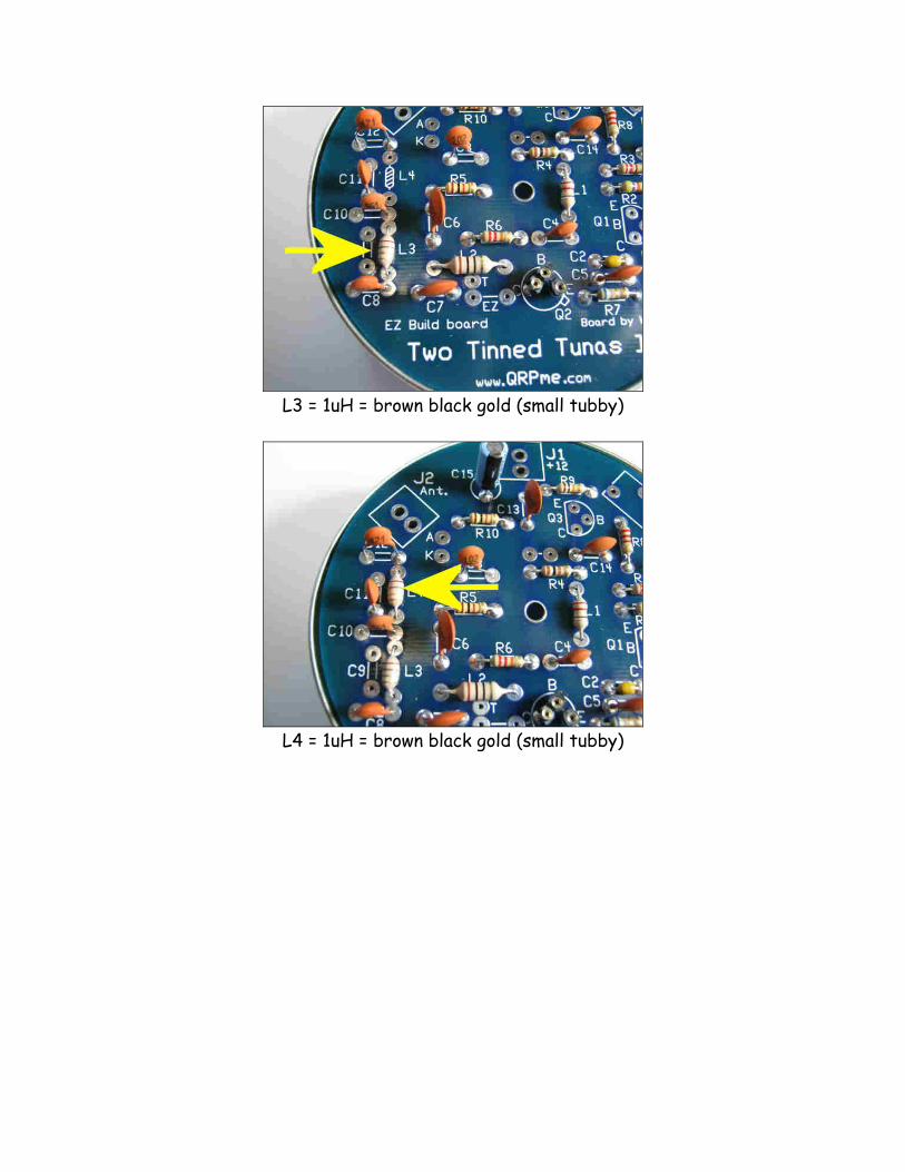
L3 = 1uH = brown black gold (small tubby)
L4 = 1uH = brown black gold (small tubby)

The potentiometer is next. P1 is a 100 ohm potentiometer and can come in several styles.
Sample trimmer pot styles.
The most likely style of pot included in your TTT kit is the round blue pot at 12 o’clock in the picture. It will either have 100 ohms or 101 printed on the
case.
Solder P1 in just to the bottom of the crystal socket X1. Make sure that the adjustment slot is towards the output of the board.

Now install the transistors.
Q1 = 2N2222A in a TO92 epoxy bodyNote the flat side orientation of the transistor as indicated by the silk screen marking on the board. Align the transistor to match the flat side
with the markings on the board.
Q2 – 2N2222A in a TO-18 metal canThe lead closest to the little tab sticking out the side is the emitter or E
lead.

Q3 is a 2N3906 transistor in a TO92 epoxy body. Again, note the silk screen marking and align the flat side of the transistor to match.
Now install the LED in the holes marked A & K. The markings represent:
A = Anode K = Cathode which is the lead coming from the flat side on the LED
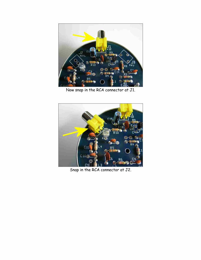
Now snap in the RCA connector at J1.
Snap in the RCA connector at J2.

Snap in the keying jack at J3.
Use a piece of component lead cut from a previous part to fashion a jumper in the 2 pads just to the top of R4. Spread the leads slightly where they
come out on the other side of the board.

Using another cut component lead, install another shorting jumper at the 2 pads marked EZ. Now flip the board over, set in on the can lip and solder the
connectors and jumpers. Clip off the excess jumper leads.
Mount the board onto the lip of the can and then secure it to the can using the long bolt and nut. Don’t over-tighten the bolt.

Now install the 40m crystal into the crystal socket marked X1. You can interchange crystals easily, as long as you stay in the 40m band.
From the front, your finished EZ Build Two Tinned Tunas kit should look like this!
FINI!