assembly instructions for the cyber
TRANSCRIPT
8/11/2019 Assembly Instructions for the Cyber
http://slidepdf.com/reader/full/assembly-instructions-for-the-cyber 1/4
Amy Williams
WLLAMY004
ASSEMBLY INSTRUCTIONS FOR THE CYBERACER© BALANCE BIKE:
Thank you for purchasing the CybeRacer© Balance Bike. This set of instructions contains details on how to
assemble the CybeRacer© Balance Bike from the parts included in the box. Some of the parts come pre-
assembled. For safety reasons, please follow these instructions carefully and in the order in which they arepresented. When purchasing the balance bike, check that all components are included in the packaging. The
assembly of this item should be done by an adult at own risk.
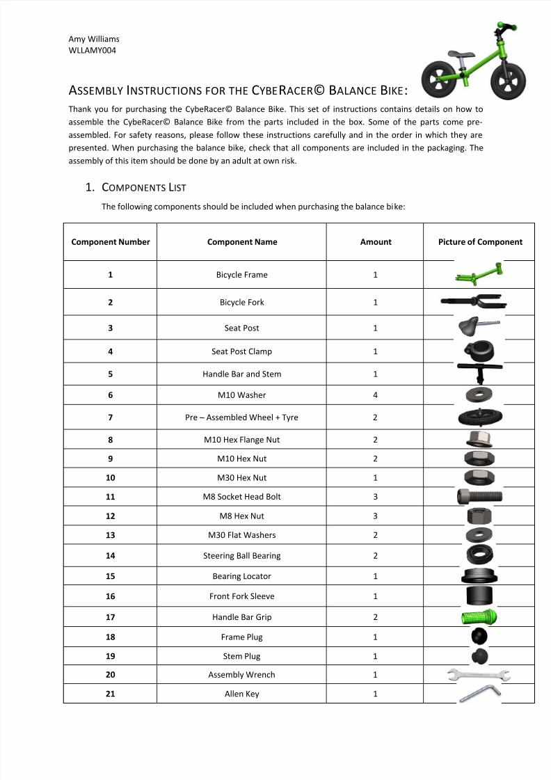
1. COMPONENTS LIST
The following components should be included when purchasing the balance bike:
Component Number Component Name Amount Picture of Component
1 Bicycle Frame 1
2 Bicycle Fork 1
3 Seat Post 1
4 Seat Post Clamp 1
5 Handle Bar and Stem 1
6 M10 Washer 4
7 Pre – Assembled Wheel + Tyre 2
8 M10 Hex Flange Nut 2
9 M10 Hex Nut 2
10 M30 Hex Nut 1
11 M8 Socket Head Bolt 3
12 M8 Hex Nut 3
13 M30 Flat Washers 2
14 Steering Ball Bearing 2
15 Bearing Locator 1
16 Front Fork Sleeve 1
17 Handle Bar Grip 2
18 Frame Plug 1
19 Stem Plug 1
20 Assembly Wrench 1
21 Allen Key 1

8/11/2019 Assembly Instructions for the Cyber
http://slidepdf.com/reader/full/assembly-instructions-for-the-cyber 2/4
Amy Williams
WLLAMY004
2. FORK AND HANDLEBAR ASSEMBLY
This section explains how to assemble the front fork and the handlebar to the frame of the bike. The
exploded handlebar/fork assembly is shown below:
1.
Place the steering ball bearings (part 14) onto the bottom and top parts of the steering tube of
the frame (part 1) until it rests on the shoulders inside the tube.
2. Place M30 Flat washers (part 13) flush against the bearing inside both the top and bottom sides
of the steering tube of the frame.
3. Place the front fork into the steering tube of the frame (part 1) and slide the tube up until it
cannot move any further (the steering tube sits right up against the shoulder of the front fork).
CAUTION: Ensure that the fork is aligned properly.
4. Place the bearing locator (part 15) onto the top of the fork, sliding it up against the washer.
5.
Grip the bearing locater and the front fork and twist to fasten.
6.
Screw the M30 Hex Nut (part 10) over the front fork and fasten the Hex Nut to the front fork.
7. Place the front fork sleeve (part 16) over the fork so that it touches the M30 Hex Nut.
8.
Place the handlebar and stem (part 5) over the front fork. Ensure that the flat face coincides with
flat face of the front fork (i.e. Ensure that the handlebars face directly forward and the stem
backward).
9.
Insert the two M8 Socket Head Bolts (part 11) through Stem holes and fasten them with two M8
Hex Nuts (part 10) using the Allen key (part 21) and wrench (part 20) provided.
10.
Insert the stem plug (part 19 ) into the stem and slide on the handlebar grips (part 17)
Figure 1: Exploded Fork/Handlebar Assembly

8/11/2019 Assembly Instructions for the Cyber
http://slidepdf.com/reader/full/assembly-instructions-for-the-cyber 3/4
Amy Williams
WLLAMY004
3. WHEEL, RIM AND AXLE ASSEMBLY
This section details the procedure followed in order to assemble the axle to the rim and the fork. The
following procedure should be applied to both the front and rear forks when attaching them to the
wheels:
1.
Insert pre-assembled wheel (part 7) into the slots in the front/back fork of the frame and place
an M10 Flat washer (part 6) on either side of the axle so that they sit flush up against the fork.
2. Screw the M10 Hex Nuts (part 9) and Flange Hex Nuts (part 8) onto the axle and fasten the nuts
to the front/back fork as shown in the diagram above. CAUTION –
excessive tightening candamage the thread on the shaft.
4. WHEEL BEARING REPLACEMENT
1.
Remove the sleeve on either ends of the wheel.
2.
Squeeze and remove circlips from the inside of the rim housing.3.
Pull axle through the rim to allow the ball bearings to be removed from the housing of the rim.
Figure 2: Exploded Front Wheel/Rim/Axle Assembly Figure 3: Completed Front Wheel/Rim/Axle Assembly
Figure 4: Exploded Wheel/Axle Assembly
8/11/2019 Assembly Instructions for the Cyber
http://slidepdf.com/reader/full/assembly-instructions-for-the-cyber 4/4
Amy Williams
WLLAMY004
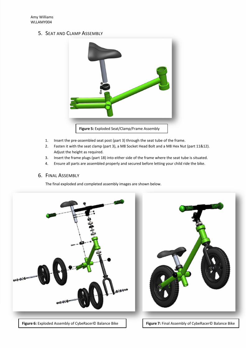
5. SEAT AND CLAMP ASSEMBLY
1.
Insert the pre-assembled seat post (part 3) through the seat tube of the frame.
2.
Fasten it with the seat clamp (part 3), a M8 Socket Head Bolt and a M8 Hex Nut (part 11&12).
Adjust the height as required.
3.
Insert the frame plugs (part 18) into either side of the frame where the seat tube is situated.
4.
Ensure all parts are assembled properly and secured before letting your child ride the bike.
6. FINAL ASSEMBLY
The final exploded and completed assembly images are shown below.
Figure 5: Exploded Seat/Clamp/Frame Assembly
Figure 6: Exploded Assembly of CybeRacer© Balance Bike Figure 7: Final Assembly of CybeRacer© Balance Bike