assembly and installation instructions of an electrofusion ... · assembly and installation...
TRANSCRIPT

Assembly and installation instructions of an
electrofusion TANK SUMP
ModelS22TS
INSTALLATION TOOLS SHOWN ON PAGE 11


I
INDEX ASSEMBLYANDINSTALLATIONOFATANKSUMP.....................................................1
1 INTRODUCTIONANDGENERALINFORMATION.....................................................................................12 APPLICATIONS....................................................................................................................................13 TRANSPORTANDHANDLING...............................................................................................................24 INSTRUCTIONS...................................................................................................................................34.1 ASSEMBLYOFSUMPBASEONTHECOLLAR.......................................................................................34.2 TANKSUMPASSEMBLYINSTRUCTIONS..............................................................................................54.3 BACKFILLINGPROCEDURES..............................................................................................................10ITEMSREQUIREDFORTHECONNECTIONOFPIPINGTOTHETANKSUMP.................................................11RECOMMENDEDTOOLSANDEQUIPMENTNECESSARYFORTHEASSEMBLY.............................................13
230E02 - 2010 01

II

1
ASSEMBLY AND INSTALLATION OF A TANK SUMP
1 INTRODUCTION AND GENERAL INFORMATION
SMARTFLEXtanksumps,alongwithpipes,fittingsandaccessories,formacompletesystemforsecondarycontainment.Thesesectionscontaininformationabouttanksumpsandtheprocedurestoensuretheircorrectinstallation.Itisimportanttoreadthissectionpriortocommencingtheinstallation.
The sumps described in this manual are not watertight, but upon request, a clamping device is available that allows the water tightness of the entire system for applications where high ground water is present. (Model SCLD4536 or Model SCLD5238).
2 APPLICATIONS
SMARTFLEXsystemprovidesfourtanksumpmodels:S22TS5238, S22TS4536, S22TS5238HBD* and S22TS4536HBD*.SMARTFLEXtanksumpsmustbeplacedinthespacebetweenthecontainmentskirt’suppersideandgrade.Sumpsareveryimportantelementsofthesystem,theirfunctionbeingthatofatwo-wayliquidisolationchamber,thuspreventing:• theenteringofgroundwaterandanyotherexternalliquid;• anyleakageofanycontainedproductfromthesumpintotheenvironment.AllSMARTFLEXsumpsaremadeofHDPEwhichensuretheyarechemicallyandstructurallysuitableforburiedapplications.
*Thesetanksumpsaredesignedforhighburialdepthorgroundwaterconditionsorsandbackfill.
2
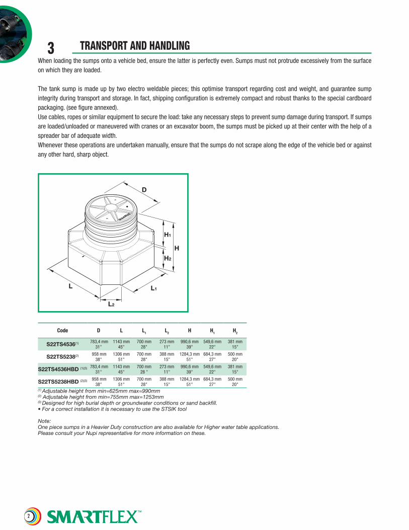
3 TRANSPORT AND HANDLINGWhenloadingthesumpsontoavehiclebed,ensurethelatterisperfectlyeven.Sumpsmustnotprotrudeexcessivelyfromthesurfaceonwhichtheyareloaded.
Thetanksumpismadeupbytwoelectroweldablepieces; thisoptimisetransportregardingcostandweight,andguaranteesumpintegrityduringtransportandstorage.Infact,shippingconfigurationisextremelycompactandrobustthankstothespecialcardboardpackaging.(seefigureannexed).Usecables,ropesorsimilarequipmenttosecuretheload:takeanynecessarystepstopreventsumpdamageduringtransport.Ifsumpsareloaded/unloadedormaneuveredwithcranesoranexcavatorboom,thesumpsmustbepickedupattheircenterwiththehelpofaspreaderbarofadequatewidth.Whenevertheseoperationsareundertakenmanually,ensurethatthesumpsdonotscrapealongtheedgeofthevehiclebedoragainstanyotherhard,sharpobject.
Code D L L1 L2 H H1 H2
S22TS4536(1) 783,4mm31"
1143mm45"
700mm28"
273mm11"
990,6mm39"
549,6mm22"
381mm15"
S22TS5238(2) 958mm38"
1306mm51"
700mm28"
388mm15"
1284,3mm51"
684,3mm27"
500mm20"
S22TS4536HBD (1)(3) 783,4mm31"
1143mm45"
700mm28"
273mm11"
990,6mm39"
549,6mm22"
381mm15"
S22TS5238HBD (2)(3) 958mm38"
1306mm51"
700mm28"
388mm15"
1284,3mm51"
684,3mm27"
500mm20"
(1) Adjustable height from min=625mm max=990mm(2) Adjustable height from min=755mm max=1253mm(3) Designed for high burial depth or groundwater conditions or sand backfill.• For a correct installation it is necessary to use the STSIK tool
Note:One piece sumps in a Heavier Duty construction are also available for Higher water table applications.Please consult your Nupi representative for more information on these.
L1
H1
H2
D
H
L
L2
3
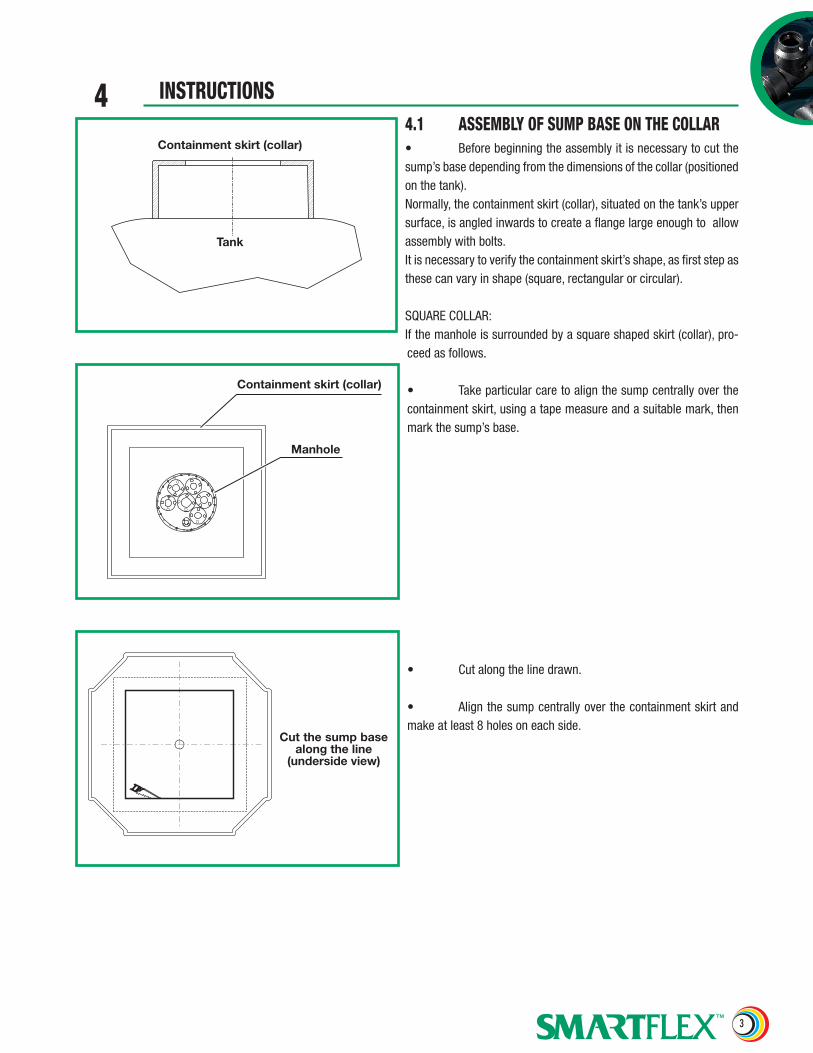
4 INSTRUCTIONS4.1 ASSEMBLY OF SUMP BASE ON THE COLLAR• Beforebeginningtheassemblyitisnecessarytocutthesump’sbasedependingfromthedimensionsofthecollar(positionedonthetank).Normally,thecontainmentskirt(collar),situatedonthetank’suppersurface,isangledinwardstocreateaflangelargeenoughtoallowassemblywithbolts.Itisnecessarytoverifythecontainmentskirt’sshape,asfirststepasthesecanvaryinshape(square,rectangularorcircular).
SQUARECOLLAR:Ifthemanholeissurroundedbyasquareshapedskirt(collar),pro-ceedasfollows.
• Takeparticularcaretoalignthesumpcentrallyoverthecontainmentskirt,usingatapemeasureandasuitablemark,thenmarkthesump’sbase.
• Cutalongthelinedrawn.
• Alignthesumpcentrallyoverthecontainmentskirtandmakeatleast8holesoneachside.
Containment skirt (collar)
Tank
Manhole
Containment skirt (collar)
Cut the sump base along the line
(underside view)
4
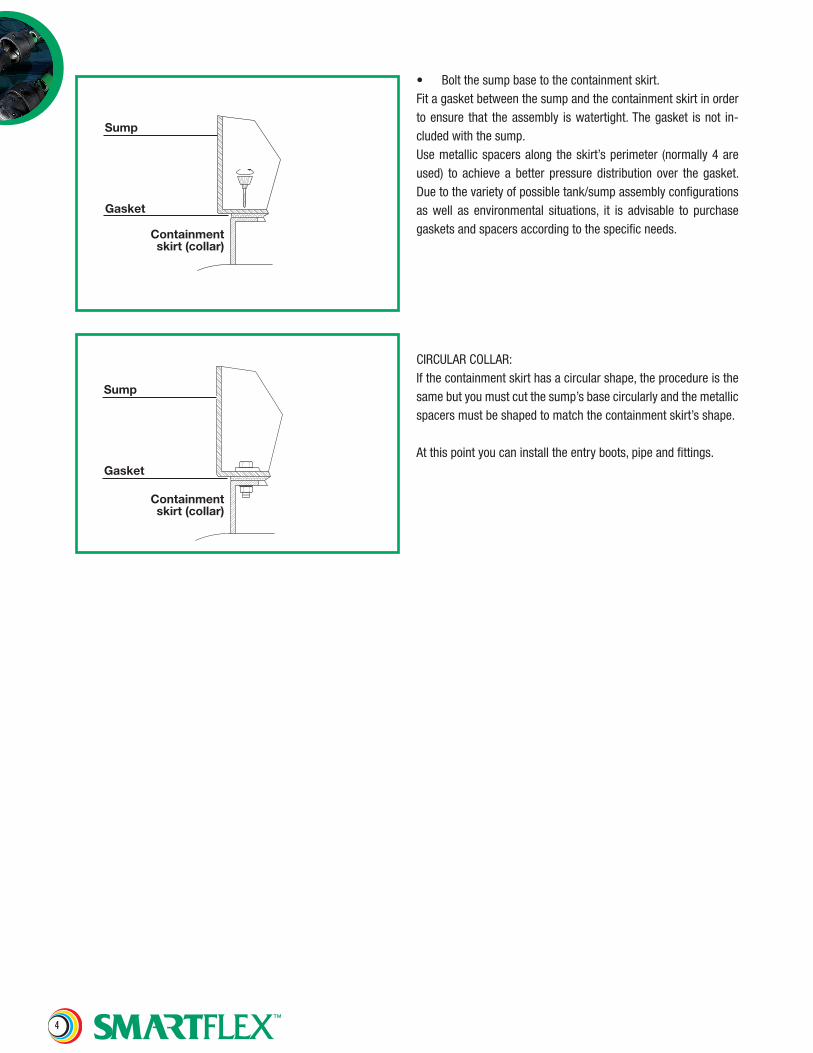
Sump
Gasket
Containmentskirt (collar)
Sump
Gasket
Containmentskirt (collar)
• Boltthesumpbasetothecontainmentskirt.Fitagasketbetweenthesumpandthecontainmentskirtinordertoensure that theassembly iswatertight.Thegasket isnot in-cludedwiththesump.Usemetallicspacersalong theskirt’sperimeter (normally4areused) to achieve a better pressure distribution over the gasket.Duetothevarietyofpossibletank/sumpassemblyconfigurationsas well as environmental situations, it is advisable to purchasegasketsandspacersaccordingtothespecificneeds.
CIRCULARCOLLAR:Ifthecontainmentskirthasacircularshape,theprocedureisthesamebutyoumustcutthesump’sbasecircularlyandthemetallicspacersmustbeshapedtomatchthecontainmentskirt’sshape.
Atthispointyoucaninstalltheentryboots,pipeandfittings.

5
Scrapethesurfacetobeweldedwiththemanualscraper(ModelRAM1), then clean all the components involved in the weldingprocesswithacleanclothsoakedwitharecommendedcleaningsolvent(ModelLID1).
Note: Thefollowingsolventsmaybeused,Acetone,IsopropylAlcohol,TrichloroethaneandDichloromethane.Theuseofotherprimersorsolventsisnotallowed.
Fig.2
Fig.1
Note: As first step, it is necessary to cut out the base of the sump to the correct shape and dimensions so It can be centred on the tank manway collar. Please take Into consideration the direction of the pipework.
Attention: In order to have suitable space necessary to assemble the various components inside the sump, we recom-mend you to electro-weld the upper section at the completion of the process.
Note: Whenscraping,aperfectlyevensurfaceIsrequired,pleasetakecaretoremoveanyroughnessthatcouldcausetheweldtobeunsuccessful.
Positiontheuppersectionofthesumponitsbase.Pleasetakecarenottodamagetheconnectorsnecessaryfortheweldingprocessandcorrectlyalignthewhitearrowsshownonbothcomponents.
4.2 TANK SUMP ASSEMBLY INSTRUCTIONS

6
Weld the sumpusing the specificbar codesuppliedwitheverysump,followingtheinstructionsshownontheweldingmachine’sdisplay.
Fig.3
Fig.4
Secure the two components together using 12 clamps (8 posi-tionedonthecornersand4centredonthelongsides).
Note:Ifpossible,trytoattainaconstantgapbetweentheclampandthesump’sedge.ThisUseblocksundertheclampstodistributethepressureload,thiswillfurtherassisttheweldingprocess.

7
During the cooling down time further tighten the clamps to in-creasetheadhesionbetweenthetwocomponents.
Fig.6
Fig.5
Waituntil thecoolingdown timeshownon thebar codeof thesumptoelapse,thenremovetheclamps.
Beforepositioningthelidontheriser(upper)sectionofthesump,ensure that thegasket/seal is correctlypositionedon the riserslipandisnotdamagedinanyway.Thisisnecessarytoobtainaneffectiveseal.
Affixtheprovidedhandlestocompletetheinstallation.
8
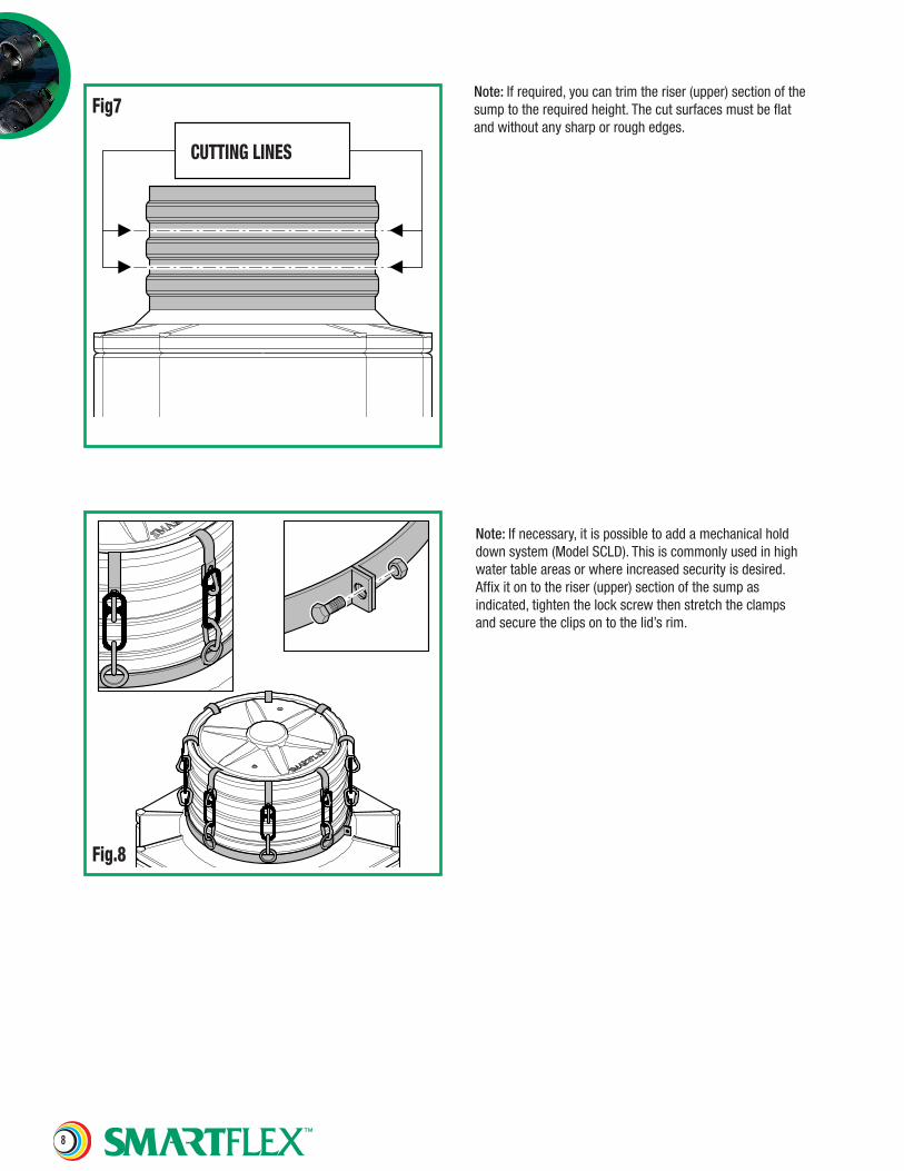
Note: Ifrequired,youcantrimtheriser(upper)sectionofthesumptotherequiredheight.Thecutsurfacesmustbeflatandwithoutanysharporroughedges.
Fig7
CUTTING LINES
Fig.8
Note: Ifnecessary,itispossibletoaddamechanicalholddownsystem(ModelSCLD).Thisiscommonlyusedinhighwatertableareasorwhereincreasedsecurityisdesired.Affixitontotheriser(upper)sectionofthesumpasindicated,tightenthelockscrewthenstretchtheclampsandsecuretheclipsontothelid’srim.

9
Note: Toperformavacuumtestonthelidisnecessarytofollowthesesteps:
1. Removethehandle.
2. Drilla6mmholethroughthebaseofthehandleassemblypointonthelid.
3. Screwthequickfitconnector(ModelSVT6)properlysealedwiththreadsealantintothehandlethread.
4. Connectthespecifictesttubeforthetest(ModelSTT6).
5. Connecttheejector(ModelSVE)tothecompressorlinetogenerateavacuumtocommencethevacuumtest.
6. Connectthetestlinetothevacuumtestunit(ModelSVTU)followingthespecificinstructions.
Thevacuumtestforbothtanksumps(ModelsS22TS4536andS22TS5238)shallbeperformedataPg=-0.15barfor30minutes(tosimulateaburialdepthof1.5metres).
Fig.9
Fig.10
STT6
SVT6
S22TS
SVE
SVTU
CompressedAir Feed
Note:Oncethetestiscompleteitisrecommendedtoreplacethehandleonthelid,sealingthethreadwithathreadsealant.
10
Attention: All backfilling materials must be dry and free from snow, ice and debris, the use of different materials from those specified may cause serious damage and/or affect the performance of the Smartflex sump and the warranty.
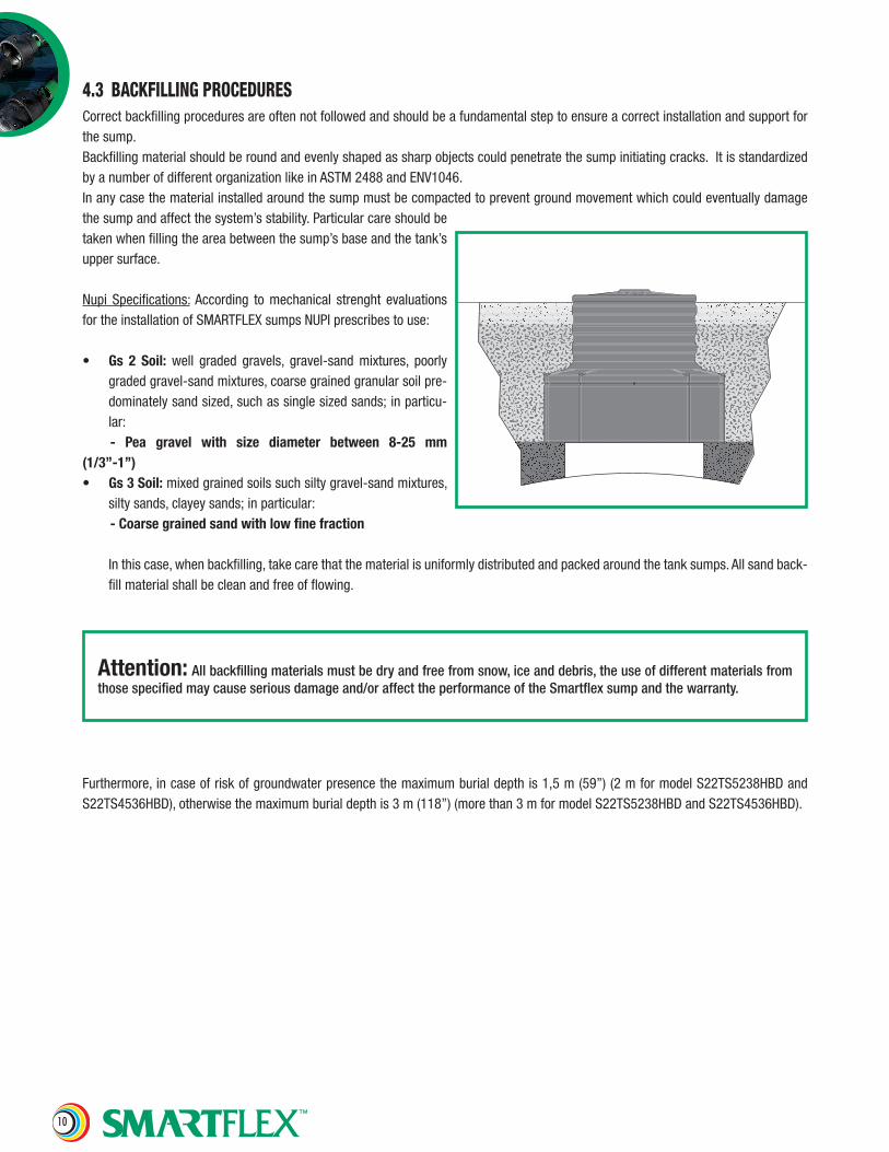
4.3 BACKFILLING PROCEDURESCorrectbackfillingproceduresareoftennotfollowedandshouldbeafundamentalsteptoensureacorrectinstallationandsupportforthesump.Backfillingmaterialshouldberoundandevenlyshapedassharpobjectscouldpenetratethesumpinitiatingcracks.ItisstandardizedbyanumberofdifferentorganizationlikeinASTM2488andENV1046.Inanycasethematerialinstalledaroundthesumpmustbecompactedtopreventgroundmovementwhichcouldeventuallydamagethesumpandaffectthesystem’sstability.Particularcareshouldbetakenwhenfillingtheareabetweenthesump’sbaseandthetank’suppersurface.
Nupi Specifications:According to mechanical strenght evaluationsfortheinstallationofSMARTFLEXsumpsNUPIprescribestouse:
• Gs 2 Soil: well graded gravels, gravel-sand mixtures, poorlygradedgravel-sandmixtures,coarsegrainedgranularsoilpre-dominatelysandsized,suchassinglesizedsands;inparticu-lar:
- Pea gravel with size diameter between 8-25 mm(1/3”-1”)• Gs3Soil:mixedgrainedsoilssuchsiltygravel-sandmixtures,
siltysands,clayeysands;inparticular: -Coarsegrainedsandwithlowfinefraction
Inthiscase,whenbackfilling,takecarethatthematerialisuniformlydistributedandpackedaroundthetanksumps.Allsandback-fillmaterialshallbecleanandfreeofflowing.
Furthermore,incaseofriskofgroundwaterpresencethemaximumburialdepthis1,5m(59”)(2mformodelS22TS5238HBDandS22TS4536HBD),otherwisethemaximumburialdepthis3m(118”)(morethan3mformodelS22TS5238HBDandS22TS4536HBD).
11
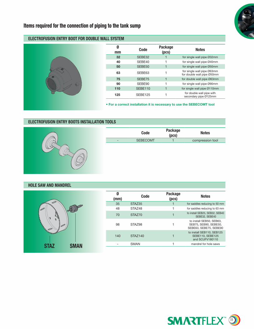
ELECTROFUSIONENTRYBOOTFORDOUBLEWALLSYSTEM
Ømm
CodePackage
(pcs)Notes
32 SEBE32 1 for single wall pipe Ø32mm
40 SEBE40 1 for single wall pipe Ø40mm
50 SEBE50 1 for single wall pipe Ø50mm
63 SEBE63 1 for single wall pipe Ø63mm for double wall pipe Ø50mm
75 SEBE75 1 for double wall pipe Ø63mm
90 SEBE90 1 for single wall pipe Ø90mm
110 SEBE110 1 for single wall pipe Ø110mm
125 SEBE125 1 for double wall pipe with secondary pipe Ø125mm
• For a correct installation it is necessary to use the SEBECOMT tool
ELECTROFUSIONENTRYBOOTSINSTALLATIONTOOLS
CodePackage
(pcs)Notes
- SEBECOMT 1 compression tool
HOLESAWANDMANDREL
Ø(mm)
CodePackage
(pcs)Notes
35 STAZ35 1 for saddles reducing to 50 mm
48 STAZ48 1 for saddles reducing to 63 mm
70 STAZ70 1 to install SEB25, SEB32, SEB40 SEBE32, SEBE40
98 STAZ98 1to install SEB50, SEB63, SEB75, SEB90, SEBE50,
SEBE63, SEBE75, SEBE90
140 STAZ140 1to install SEB110, SEB125
SEBE110, SEBE125 and SCUFV180110
- SMAN 1 mandrel for hole sawsSMANSTAZ
Items required for the connection of piping to the tank sump

12
ENTRYBOOT
Ø(mm)
CodePackage
(pcs)Notes
25 SEB25 132 SEB32 1 for single wall pipe Ø32mm
40 SEB40 1 for single wall pipe Ø40mm
50 SEB50 1 for single wall pipe Ø50mm
63 SEB63 1for single wall pipe Ø63 and for double wall pipe Ø50mmfor secondary pipe Ø63mm
75 SEB75 1 for double wall pipe Ø63mmfor secondary pipe Ø75mm
90 SEB90 1 for single wall pipe Ø90mm
110 SEB110 1 for single wall pipe Ø110mm
125 SEB125 1 for double wall pipe with secondary pipe Ø125mm
ENTRYBOOT/TERMINATINGFITTINGINSTALLATIONKIT
Ø(mm)
CodePackage
(pcs)Notes
25 - 180 SSET4 1
Thekitincludes:-nr.1template(STEM)-nr.1mandrel(SMAN)-nr.3holesaws(STAZ70,STAZ98,STAZ140)
13
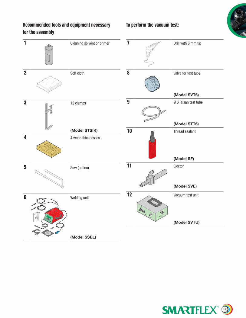
1 Cleaningsolventorprimer
2 Softcloth
3 12clamps
(Model STSIK)
4 4woodthicknesses
5 Saw(option)
6 Weldingunit
(Model SSEL)
7 Drillwith6mmtip
8 Valvefortesttube
(Model SVT6)
9 Ø6Rilsantesttube
(Model STT6)
10 Threadsealant
(Model SF)
11 Ejector
(Model SVE)
12 Vacuumtestunit
(Model SVTU)
Recommended tools and equipment necessary for the assembly
To perform the vacuum test:

14
ThisdocumentispropertyofNUPIGECOS.p.a,nopartofitmaybecopiedorreproduced,with-outpriorwrittenconsentfromNUPIGECO.NUPIGECOS.p.areservestherighttomaketheop-portunetechnicalmodificationswithoutnotice.NUPIGECOS.p.adoesn’tguaranteethecorrectoperationofthesystemincasetheinformationcontainedinthisdocumentarenotfollowed.
NUPIGECO SpAViadell’Artigianato,13-40023CastelGuelfodiBologna-ItalyPhone(39)0331344211-Fax(39)0542670851E-Mail: [email protected] - Web Site: www.nupigeco.com
NUPI Americas, Inc.1511SuperiorWay,Houston,TX77039Phone(281)5904471-Fax(281)5905268E-Mail: [email protected] - Web Site: www.nupiamericas.com