aspt series - fl cooling · • the chart is for informaion only. for saisfactory operaion,...
TRANSCRIPT

SS-GASPT www.goodmanmfg.com 5/15Supersedes 3/15
ASPT SeriesMulti-Position, Multi-Speed,
ECM-Based Air Handler with Internal TXV
1½ to 5 TonsContents
Air Handler Nomenclature .................... 2
Heater Kit Nomenclature ...................... 2
Product Specifications ........................... 3
Dimensions ............................................ 4
Airflow Data ........................................... 6
Heat Kit Data .......................................... 7
Wiring Diagram ...................................... 9
Accessories .......................................... 12
Product Features
• Internal factory-installed thermal expansion valves for cooling and heat pump applications
• Direct drive, multi-speed ECM blower motor• All-aluminum evaporator coil
• Coil mounting track for quick repositioning• Optimized for use with R-410A refrigerant• Cabinet air leakage less than 2.0%
at 1.0 inch H₂O when tested in accordance with ASHRAE standard 193
• Cabinet air leakage less than 1.4% at 0.5 inch H₂O when tested in accordance with ASHRAE standard 193
• 3 kW – 25 kW electric heater kits• AHRI certified; ETL listed
• Rigid SmartFrame™ cabinet• Horizontal or vertical
configuration capabilities • 21” depth for easier attic access• DecaBDE-free thermoplastic drain
pan with secondary drain connections• Screw-less sides and back helps
to reduce condensation when installed in humid locations
• Foil-faced insulation covers the internal casing to reduce cabinet condensation
• Galvanized, leather grain-embossed finish• Glue-less cabinet insulation retention • Tool-less filter access
* Complete warranty details available from your local dealer or at www.goodmanmfg.com. To receive the 10-Year Parts Limited Warranty, online registration must be completed within 60 days of installation. Online registration is not required in California or Québec.
2 www.goodmanmfg.com SS-GASPT
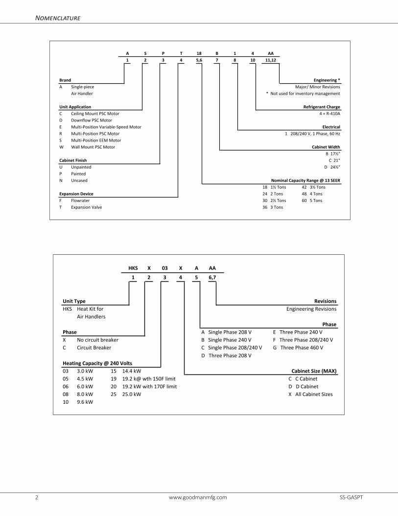
HKS X 03 X A AA
1 2 3 4 5 6,7
Unit Type RevisionsHKS Heat Kit for Engineering Revisions
Air HandlersPhase
Phase A Single Phase 208 V E Three Phase 240 VX No circuit breaker B Single Phase 240 V F Three Phase 208/240 VC Circuit Breaker C Single Phase 208/240 V G Three Phase 460 V
D Three Phase 208 VHeating Capacity @ 240 Volts03 3.0 kW 15 14.4 kW Cabinet Size (MAX)05 4.5 kW 19 19.2 k@ wth 150F limit C C Cabinet06 6.0 kW 20 19.2 kW with 170F limit D D Cabinet08 8.0 kW 25 25.0 kW X All Cabinet Sizes10 9.6 kW
B 1 7 8
Brand Engineering *A Single-‐piece Major/ Minor Revisions
Air Handler * Not used for inventory management
Unit Application Refrigerant ChargeC Ceiling Mount PSC Motor 4 = R-‐410AD Downflow PSC MotorE Multi-‐Position Variable-‐Speed Motor ElectricalR Multi-‐Position PSC Motor 1 208/240 V, 1 Phase, 60 HzS Multi-‐Position EEM MotorW Wall Mount PSC Motor Cabinet Width
B 17½"Cabinet Finish C 21"U Unpainted D 24½"P PaintedN Uncased Nominal Capacity Range @ 13 SEER
18 1½ Tons 42 3½ TonsExpansion Device 24 2 Tons 48 4 TonsF Flowrater 30 2½ Tons 60 5 TonsT Expansion Valve 36 3 Tons
S2 5,6
181A AA
11,12P3
T4 10
4
Nomenclature

SS-GASPT www.goodmanmfg.com 3
ASPT
25B14*
ASPT
29B14*
ASPT
37B14*
ASPT
37C14*
ASPT
47C14*
ASPT
59C14*
ASPT
47D14*
ASPT
49D14*
ASPT
61D14*
Nominal Ratings
Cooling (Btu/h) 24,000 24,000 30,000 36,000 42,000 60,000 42,000 48,000 60,000
Blower
Diameter 9½" 9½" 9½" 10⅝" 10⅝" 10⅝" 10⅝" 11¹⁵⁄₁₆" 11¹⁵⁄₁₆"
Width 6" 6" 6" 8" 10⅝" 10⅝" 10⅝" 10⅝" 10⅝"
Coil ConnectionsLiquid ⅜" ⅜" ⅜" ⅜" ⅜" ⅜" ⅜" ⅜" ⅜"
Suction ¾" ⅞" ⅞" ⅞" ⅞" ⅞" ⅞" ⅞" ⅞"
Coil Drain Connect (FPT) ¾" ¾" ¾" ¾" ¾" ¾" ¾" ¾" ¾"
Electrical Data
Voltage 208 / 230 208 / 230 208 / 230 208 / 230 208 / 230 208 / 230 208 / 230 208 / 230 208 / 230
Minimum Circuit Ampacity 5.8 / 5.8 5.8 / 5.8 5.6 / 5.6 5.6 / 5.6 5.6 / 5.6 7.9 / 7.9 5.6 / 5.6 8.6 / 8.6 8.6 / 8.6
Max. Overcurrent Device (Amps) 15 / 15 15 / 15 15 / 15 15 / 15 15 / 15 15/15 15 / 15 15 / 15 15 / 15
Minimum VAC 197 197 197 197 197 197 197 197 197
Maximum VAC 253 253 253 253 253 253 253 253 253
Blower Motor
Full Load Amps (FLA) 4.6 4.6 4.5 4.5 4.5 6.3 4.5 6.9 6.9
Horsepower (HP) ¾ ¾ ¾ ¾ ¾ 1 ¾ 1 1
Ship Weight (Lbs.) 116 129 129 144 144 144 155 167 167
*Airflow rate @.3 static Note: Assumes dry coil; SCFM correction for wet coil = 4% (208V / 240V)
Product Specifications
4 www.goodmanmfg.com SS-GASPT
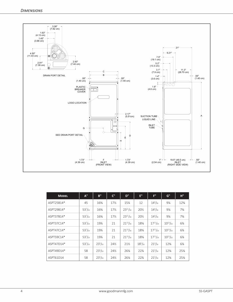
Dimensions
C
B
.55"(1.40 cm)
.55"(1.40 cm)
2.17"(5.51cm)
DE
21"
9.21"
11.3"(28.70 cm)
.55"(1.40 cm)
A
FINLET
(FRONT VIEW)
1"(2.54 cm)
.55"(1.40 cm)
19.5" (49.5 cm)INLET
(RIGHT SIDE VIEW)
1.73"(4.39 cm)
1.73"(4.39 cm)
1.45"(3.68 cm)
3.08"(7.82 cm)
1.63"(4.13 cm)
2.91"(7.39 cm)
2.93"(7.44 cm)
G
H
4.50"(11.43 cm)
1.4"(3.6 cm)
3.1"(7.9 cm)
5.2"(13.3 cm)
7.5"(19.1 cm)
1.8"(4.6 cm)
PLASTICBREAKER
COVER
LOGO LOCATION
SEE DRAIN PORT DETAIL
LIQUID LINE
SUCTION TUBE
INLETTUBE
DRAIN PORT DETAIL
Model A" B" C" D" E" F" G" H"
ASPT25B14* 45 16⅜ 17½ 15¼ 12 143/16 9⅛ 12⅝
ASPT29B14* 537/16 16⅜ 17½ 2311/16 20½ 143/16 9⅛ 7⅝
ASPT37B14* 537/16 16⅜ 17½ 2311/16 20½ 143/16 9⅛ 7⅝
ASPT37C14* 537/16 19⅞ 21 2113/16 18⅝ 1711/16 1013/16 6⅞
ASPT47C14* 537/16 19⅞ 21 2113/16 18⅝ 1711/16 1013/16 6⅞
ASPT59C14* 537/16 19⅞ 21 2113/16 18⅝ 1711/16 1013/16 6⅞
ASPT47D14* 537/16 235/16 24½ 21½ 185/16 213/16 12⅝ 6⅞
ASPT49D14* 58 235/16 24½ 26⅛ 22⅞ 213/16 12⅝ 25⅛
ASPT61D14 58 235/16 24½ 26⅛ 22⅞ 213/16 12⅝ 25⅛

SS-GASPT www.goodmanmfg.com 5
Dimensions (Cont.)
Model A" B" C" D" E" F" G" H"
ASPT61D14 58 235/16 24½ 26⅛ 22⅞ 213/16 12⅝ 25⅛

6 www.goodmanmfg.com SS-GASPT
Airflow Data
Model SpeedTap
Static Pressure (in w.c)
0.1 0.2 0.3 0.4 0.5 0.6 0.7 0.8 0.9 1.0
ASPT
25B14AA
1 640 585 580 545 510 490 410 340 280
2 800 765 725 700 670 645 595 565 490
3 840 805 800 760 740 700 670 625 580
4 985 950 920 885 850 815 800 760 7255 1,475 1,440 1,400 1,375 1,335 1,305 1,270 1,240 1,150
ASPT
29B14AA
1 595 590 565 530 505 455 380 305 2602 790 775 745 705 665 625 585 515 445
3 865 820 790 770 735 695 645 595 530
4 1,015 980 955 925 880 840 795 770 7205 1,505 1,465 1,430 1,410 1,385 1,350 1,315 1,285 1,220
ASPT
37B14AA
1 1,025 985 945 910 875 830 795 735 690
2 1,150 1,105 1,065 1,025 995 950 915 870 825
3 1,240 1,200 1,160 1,120 1,085 1,050 1,010 970 925
4 1,425 1,400 1,355 1,320 1,290 1,250 1,215 1,180 1,1455 1,490 1,455 1,415 1,390 1,355 1,320 1,285 1,250 1,205
ASPT
37C14AA
1 980 935 895 860 825 800 755 710 665
2 1,125 1,075 1,045 1,000 965 930 880 845 820
3 1,235 1,190 1,155 1,120 1,085 1,045 1,005 965 920
4 1,485 1,450 1,425 1,390 1,355 1,315 1,275 1,230 1,1905 1,565 1,535 1,510 1,480 1,240 1,390 1,365 1,320 1,280
ASPT
47C14AA
1 955 895 855 840 780 735 675 615 5602 1,100 1,050 1,005 965 925 870 815 770 705
3 1,205 1,160 1,120 1,075 1,035 990 940 885 830
4 1,445 1,410 1,365 1,320 1,275 1,235 1,190 1,140 1,0955 1,525 1,480 1,435 1,400 1,360 1,320 1,275 1,230 1,180
ASPT
47D14AA
1 1,055 1,015 950 895 830 785 730 680 6202 1,210 1,165 1,110 1,070 1,015 960 900 840 785
3 1,335 1,290 1,250 1,205 1,145 1,100 1,050 980 910
4 1,625 1,580 1,530 1,495 1,455 1,405 1,350 1,295 1,2305 1,720 1,670 1,625 1,580 1,540 1,490 1,435 1,390 1,325
ASPT
49D14AA
1 1,485 1,435 1,380 1,320 1,265 1,200 1,230 1,015 930
2 1,570 1,525 1,480 1,430 1,370 1,315 1,235 1,155 1,035
3 1,680 1,600 1,570 1,555 1,475 1,430 1,360 1,280 1,185
4 1,800 1,765 1,715 1,670 1,625 1,590 1,510 1,465 1,3905 2,215 2,160 2,120 2,085 2,040 2,000 1,970 1,930 1,865
ASPT
59C14AA
1 1,370 1,330 1,295 1,255 1,215 1,180 1,140 1,100 1,0602 1,535 1,500 1,465 1,430 1,405 1,370 1,335 1,300 1,2103 1,680 1,645 1,615 1,575 1,545 1,510 1,440 1,330 1,2054 1,905 1,855 1,780 1,690 1,605 1,515 1,425 1,330 1,2055 1,940 1,855 1,775 1,700 1,605 1,505 1,420 1,320 1,205
ASPT
61D14AA
1 1,545 1,495 1,440 1,390 1,335 1,260 1,180 1,080 1,0302 1,745 1,695 1,625 1,575 1,525 1,475 1,400 1,360 1,275
3 1,905 1,855 1,815 1,770 1,725 1,670 1,635 1,575 1,500
4 2,155 2,105 2,090 2,045 2,000 1,970 1,935 1,890 1,8305 2,340 2,310 2,265 2,220 2,185 2,165 2,120 2,080 2,030
Notes• The chart is for information only. For satisfactory operation, external static pressure must not exceed value shown on rating plate. • Use the CFM adjustment factors of .98 for horizontal left, .95 for horizontal right & .96 for downflow orientations. • Assumes dry coil with filter in place.• All models are shipped from the factory with the speed tap set on T4.• Assumes dry coil; SCFM correction for wet coil = 4% • All ASPT models are shipped from the factory with the speed tap set on T4.
SS-GASPT www.goodmanmfg.com 7
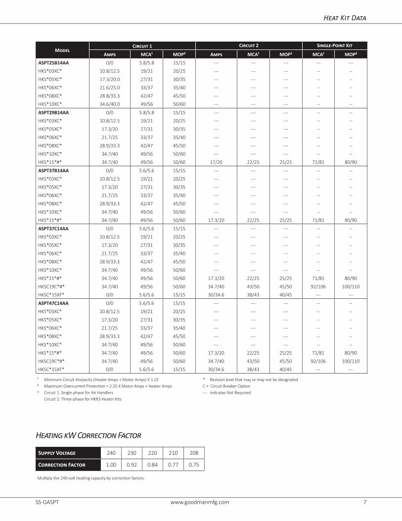
Heat Kit Data
ModelCircuit 1 Circuit 2 Single-Point Kit
Amps MCA¹ MOP² Amps MCA¹ MOP² MCA¹ MOP²ASPT25B14AA 0/0 5.8/5.8 15/15 --- --- --- --- ---
HKS*03XC* 10.8/12.5 19/21 20/25 --- --- --- -- --
HKS*05XC* 17.3/20.0 27/31 30/35 --- --- --- -- --
HKS*06XC* 21.6/25.0 33/37 35/40 --- --- --- -- --
HKS*08XC* 28.8/33.3 42/47 45/50 --- --- --- -- --
HKS*10XC* 34.6/40.0 49/56 50/60 --- --- --- -- --
ASPT29B14AA 0/0 5.8/5.8 15/15 --- --- --- -- --
HKS*03XC* 10.8/12.5 19/21 20/25 --- --- --- -- --
HKS*05XC* 17.3/20 27/31 30/35 --- --- --- -- --
HKS*06XC* 21.7/25 33/37 35/40 --- --- --- -- --
HKS*08XC* 28.9/33.3 42/47 45/50 --- --- --- -- --
HKS*10XC* 34.7/40 49/56 50/60 --- --- --- -- --
HKS*15*#* 34.7/40 49/56 50/60 17/20 22/25 25/25 71/81 80/90
ASPT37B14AA 0/0 5.6/5.6 15/15 --- --- --- -- --
HKS*03XC* 10.8/12.5 19/21 20/25 --- --- --- -- --
HKS*05XC* 17.3/20 27/31 30/35 --- --- --- -- --
HKS*06XC* 21.7/25 33/37 35/40 --- --- --- -- --
HKS*08XC* 28.9/33.3 42/47 45/50 --- --- --- -- --
HKS*10XC* 34.7/40 49/56 50/60 --- --- --- -- --
HKS*15*#* 34.7/40 49/56 50/60 17.3/20 22/25 25/25 71/81 80/90
ASPT37C14AA 0/0 5.6/5.6 15/15 --- --- --- -- --
HKS*03XC* 10.8/12.5 19/21 20/25 --- --- --- -- --
HKS*05XC* 17.3/20 27/31 30/35 --- --- --- -- --
HKS*06XC* 21.7/25 33/37 35/40 --- --- --- -- --
HKS*08XC* 28.9/33.3 42/47 45/50 --- --- --- -- --
HKS*10XC* 34.7/40 49/56 50/60 --- --- --- -- --
HKS*15*#* 34.7/40 49/56 50/60 17.3/20 22/25 25/25 71/81 80/90
HKSC19C*#* 34.7/40 49/56 50/60 34.7/40 43/50 45/50 92/106 100/110
HKSC*15XF* 0/0 5.6/5.6 15/15 30/34.6 38/43 40/45 --- ---
ASPT47C14AA 0/0 5.6/5.6 15/15 --- --- --- -- --
HKS*03XC* 10.8/12.5 19/21 20/25 --- --- --- -- --
HKS*05XC* 17.3/20 27/31 30/35 --- --- --- -- --
HKS*06XC* 21.7/25 33/37 35/40 --- --- --- -- --
HKS*08XC* 28.9/33.3 42/47 45/50 --- --- --- -- --
HKS*10XC* 34.7/40 49/56 50/60 --- --- --- -- --
HKS*15*#* 34.7/40 49/56 50/60 17.3/20 22/25 25/25 71/81 80/90
HKSC19C*#* 34.7/40 49/56 50/60 34.7/40 43/50 45/50 92/106 100/110
HKSC*15XF* 0/0 5.6/5.6 15/15 30/34.6 38/43 40/45 --- ---
Heating kW Correction Factor
Supply Voltage 240 230 220 210 208
Correction Factor 1.00 0.92 0.84 0.77 0.75
Multiply the 240-volt heating capacity by correction factors.
¹ Minimum Circuit Ampacity (Heater Amps + Motor Amps) X 1.25² Maximum Overcurrent Protection = 2.25 X Motor Amps + Heater Amps^ Circuit 1: Single-phase for Air Handlers Circuit 2: Three-phase for HKR3 Heater Kits
* Revision level that may or may not be designatedC = Circuit Breaker Option--- indicates Not Required

8 www.goodmanmfg.com SS-GASPT
Heat Kit Data (cont.)
ModelCircuit 1 Circuit 2 Single-Point Kit
Amps MCA¹ MOP² Amps MCA¹ MOP² MCA¹ MOP²ASPT59C14AA 0.0/.0.0 7.9/7.9 15/15 --- --- --- -- --
HKS*03XC* 10.8/12.5 21/24 25/25 --- --- --- -- --
HKS*05XC* 17.3/20 30/33 30/35 --- --- --- -- --
HKS*06XC* 21.7/25 35/39 35/40 --- --- --- -- --
HKS*08XC* 28.9/33.3 44/50 45/50 --- --- --- -- --
HKS*10XC* 34.7/40 51/58 60/60 --- --- --- -- --
HKS*15*#* 34.7/40 51/58 60/60 17.3/20 22/25 25/25 73/83 80/90
HKSC19C*#* 34.7/40 51/58 60/60 34.7/40 43/50 45/50 95/108 100/110
HKSC*15XF* 0.0/0.0 7.9/7.9 15/15 30/34.6 38/43 40/45 --- ---
ASPT47D14AA 0/0 5.6/5.6 15/15 --- --- --- -- --
HKS*03XC* 10.8/12.5 19/21 20/25 --- --- --- -- --
HKS*05XC* 17.3/20 27/31 30/35 --- --- --- -- --
HKS*06XC* 21.7/25 33/37 35/40 --- --- --- -- --
HKS*08XC* 28.9/33.3 42/47 45/50 --- --- --- -- --
HKS*10XC* 34.7/40 49/56 50/60 --- --- --- -- --
HKS*15*#* 34.7/40 49/56 50/60 17.3/20 22/25 25/25 71/81 80/90
HKSC20D#C* 34.7/40 49/56 50/60 34.7/40 43/50 45/50 92/106 100/110
HKSC*15XF* 0/0 5.6/5.6 15/15 30/34.6 38/43 40/45 --- ---
HKS*20XF* 0/0 5.6/5.6 15/15 37.5/43.3 47/54 50/60 --- ---
ASPT49D14AA 0/0 8.6/8.6 15/15 --- --- --- -- --
HKS*03XC* 10.8/12.5 22/24 25/25 --- --- --- -- --
HKS*05XC* 17.3/20 30.3/34 35/35 --- --- --- -- --
HKS*06XC* 21.7/25 36/40 40/40 --- --- --- -- --
HKS*08XC* 28.9/33.3 45/50.3 45/60 --- --- --- -- --
HKS*10XC* 34.7/40 52/59 60/60 --- --- --- -- --
HKSC15*#* 34.7/40 52/59 60/60 17.3/20.0 22/25 25/25 74/84 80/90
HKSC20D#* 34.7/40 52/59 60/60 34.7/40.0 43/50 45/50 95/109 100/110
HKS*15XF* 0/0 8.6/8.6 15/15 30/34.6 38/43 40/45 --- ---
HKS*20XF* 0/0 8.6/8.6 15/15 37.5/43.3 47/54 50/60 --- ---
HKSC25DC* 52/60 74/84 80/90 35/40 43/50 45/50 117/134 125/150
ASPT61D14AA 0/0 8.6/8.6 15/15 --- --- --- -- --
HKS*03XC* 10.8/12.5 22/24 25/25 --- --- --- -- --
HKS*05XC* 17.3/20 30.3/34 35/35 --- --- --- -- --
HKS*06XC* 21.7/25 36/40 40/40 --- --- --- -- --
HKS*08XC* 28.9/33.3 45/50.3 45/60 --- --- --- -- --
HKS*10XC* 34.7/40 52/59 60/60 --- --- --- -- --
HKSC15*#* 34.7/40 52/59 60/60 17.3/20.0 22/25 25/25 74/84 80/90
HKSC20D#* 34.7/40 52/59 60/60 34.7/40.0 43/50 45/50 95/109 100/110
HKS*15XF* 0/0 8.6/8.6 15/15 30/34.6 38/43 40/45 --- ---
HKS*20XF* 0/0 8.6/8.6 15/15 37.5/43.3 47/54 50/60 --- ---
HKSC25DC* 52/60 74/84 80/90 35/40 43/50 45/50 117/134 125/150
Heating kW Correction Factor
Supply Voltage 240 230 220 210 208
Correction Factor 1.00 0.92 0.84 0.77 0.75
Multiply the 240-volt heating capacity by correction factors.
¹ Minimum Circuit Ampacity (Heater Amps + Motor Amps) X 1.25² Maximum Overcurrent Protection = 2.25 X Motor Amps + Heater Amps^ Circuit 1: Single-phase for Air Handlers Circuit 2: Three-phase for HKR3 Heater Kits
* Revision level that may or may not be designatedC = Circuit Breaker Option--- indicates Not Required

SS-GASPT www.goodmanmfg.com 9
Wiri
ng is
sub
ject
to c
hang
e. A
lway
s re
fer
to t
he w
iring
dia
gram
on
the
unit
for t
he m
ost u
p-to
-dat
e w
iring
.⚠
W
arni
ngH
igh
Vo
lta
ge
: D
isco
nnec
t al
l po
wer
bef
ore
serv
icin
g or
ins
talli
ng t
his
unit.
Mul
tiple
pow
er
sour
ces
may
be
pres
ent.
Fai
lure
to d
o so
may
cau
se p
rope
rty
dam
age,
per
sona
l inj
ury,
or d
eath
.⚡
BK
BL
BK
L1
L2
BK
BK
HT
R1
TL
HT
R1
RD
987
R
WH
BL
PU
TL
BK
5 63 4
PLF
BK
RD
1 2
WH
RD
L2
L1
BK
BK
RD
BKR
D
RHT
R2
TL
L1
BK
6 8 972
RD
PU
4 53
BK
RD
1PLF
BK
L2
L1
L2
RD
YL
M1
M2
BK
RD
YL
RD
R1
M4
RD
BK
M3
HT
R3
TL
HT
R2
HT
R1
TL
TL
PU
M2
R2
YL
M1
BL
WH
BR
BL
RD
BK
RD
BK
TL
HT
R1
BK
HT
R4
HT
R3
HT
R2
BK
RD
97 8
L2
L1
L1
L2
2 5 63 4
PLF
1
RD
M1
YL
BKM
2
BL
WH
6
BL
RD
BK
YL
8 97
M6
M5
M3 R
1
M4
RD
PU
M7 R2
M8BL
TL
TL
TL Y
L
BL
RD
BK
RD B
L
BR
4 532
BK
PLF
1
ON
E (
1)
ELE
ME
NT
RO
WS
TW
O (
2)
ELE
ME
NT
RO
WS
TH
RE
E (
3)
ELE
ME
NT
RO
WS
FO
UR
(4)
ELE
ME
NT
RO
WS
FL
M1
M2
FL
FL
M1
M2
M3
M4
FL
FL
FL
FL
FL
FL
FL
CO
PP
ER
PO
WE
R S
UP
PL
Y(U
SE
RA
TIN
G P
LA
TE
)
US
E M
IN.
75
° C
FIE
LD
WIR
E
01
40A
000
63
-B
PL
M
PL
F
TR
FA
CT
OR
Y W
IRIN
G
FIE
LD
WIR
ING
NO
TE
S:
1)
RE
D W
IRE
S T
O B
E O
N T
RA
NS
FO
RM
ER
TE
RM
INA
L "
3"
FO
R 2
40 V
OLT
S A
ND
ON
TE
RM
INA
L "
2"
FO
R 2
08 V
OL
TS
.
2)
SE
E C
OM
PLE
TE
WIR
ING
DIA
GR
AM
S IN
IN
ST
ALLA
TIO
N I
NS
TR
UC
TIO
NS
FO
R
PR
OP
ER
LO
W V
OLT
AG
E W
IRIN
G C
ON
NE
CT
ION
S.
3)
CO
NF
IRM
SP
EE
D T
AP
SE
LE
CT
ION
IS
AP
PR
OP
RIA
TE
FO
R A
PP
LIC
AT
ION
. IF
SP
EE
D T
AP
NE
ED
S T
O B
E C
HA
NG
ED
, C
ON
NE
CT
PU
RP
LE
WIR
E F
RO
M T
ER
MIN
AL 4
OF
CR
RE
LA
Y T
O A
PP
RO
PR
IAT
E T
AP
AT
TB
4)
BR
OW
N A
ND
WH
ITE
WIR
ES
AR
E U
SE
D F
OR
HE
AT
KIT
S O
NLY
.
5)
FU
SE
: 3A
, 250V
, 3A
G C
AR
TR
IDG
E F
US
E.
RE
LA
Y
EV
AP
OR
AT
OR
MO
TO
R
TE
RM
INA
L B
OA
RD
REM TB
BK
RD
BL
YL
BL
UE
BL
AC
KR
ED
YE
LLO
W
CO
MP
ON
EN
T C
OD
E
BR
OW
NP
UR
PL
EG
RE
EN
PU
BR
GR
FE
MA
LE
PL
UG
CO
NN
EC
TO
R
MA
LE
PLU
G C
ON
NE
CT
OR
TR
AN
SF
OR
ME
R
H
IGH
VO
LT
AG
E L
OW
VO
LT
AG
E
H
IGH
VO
LT
AG
E L
OW
VO
LT
AG
E
PL
F
2
CO
LO
R C
OD
E
TR
65
PL
M4
42
4V
5
12
3
EM
WIR
ING
CO
DE
20
8/2
40
VO
LT
S
11P
LF
PL
M
L1
PL
M
2L2
IF R
EP
LA
CE
ME
NT
OF
TH
E O
RIG
INA
L W
IRE
S
SU
PP
LIE
D W
ITH
TH
IS A
SS
EM
BL
Y I
S N
EC
ES
SA
RY
,U
SE
WIR
E T
HA
T C
ON
FO
RM
S T
O T
HE
NA
TIO
NA
L
EL
EC
TR
IC C
OD
E.
FL
FU
SE
LIN
K
TL
TH
ER
MA
L L
IMIT
HT
RH
EA
T E
LE
ME
NT
S
CR
CO
NT
RO
L R
EL
AY
NO
TE
: W
HE
N I
NS
TA
LL
ING
HE
AT
ER
KIT
, E
NS
UR
E S
PE
ED
TA
P D
OE
S N
OT
EX
CE
ED
MIN
IMU
M B
LO
WE
R S
PE
ED
(M
BS
) S
PE
CIF
IED
FO
R T
HE
AIR
HA
ND
LE
R/H
EA
TE
R K
IT C
OM
BIN
AT
ION
ON
TH
IS
UN
IT'S
S&
R P
LA
TE
. A
FT
ER
IN
ST
ALL
ING
OP
TIO
NA
L H
EA
T K
IT,
MA
RK
A "
X"
IN T
HE
BO
X P
RO
VID
ED
AB
OV
E.M
AR
K A
CC
OR
DIN
G T
O N
UM
BE
R O
F H
EA
TE
R E
LE
ME
NT
RO
WS
IN
ST
ALLE
D.
NO
MA
RK
IND
ICA
TE
S N
O H
EA
T K
IT I
NS
TA
LL
ED
.
WH
ITE
WH
LG
N
W2
RW
1C
G4
Y1
OY
21
DH
32
5
AB
1
C
EM
2 43 5
47
CR
FU
SE
HO
LD
ER
(OP
TIO
NA
L)
1
SE
E N
OT
E 1
US
E C
OP
PE
R W
IRE
EQ
UIP
ME
NT
GR
OU
ND
BL
EM
YL
BL
5
BK
C
BK
PLF
BK1
RD2
3
240
24
V4
12
3
TR
RD
BL
BR
45
WH6
78
9P
LM
GR
D
12
34
56
78
9
AB17
4
CR
SE
E N
OT
E 2
21
43
5 NC
GL
RD
PU
BL
BR
WH
BL
RD
GR
RD
or
BK
BL
RD
BK
RD
W2
RW
1C
G4
Y1
OY
21
DH
32
5
RD
or
BK
PU
BR
WH
OR
WH
WH
BL
GR
RD
or
BK
BL
FU
SE
HO
LD
ER
(OP
TIO
NA
L)
L2
L1
SE
E
NO
TE
1
SE
E
NO
TE
4
1354
2
AL
TE
RN
AT
E H
EA
T R
ELA
Y
PU
RD
GR
WH
13
24
CR
5
ALT
ER
NA
TE
HE
AT
RE
LA
Y
Air Handler Wiring Diagram
NOTE: The five element, 25 kW heater kit is not shown above.

10 www.goodmanmfg.com SS-GASPT
Wiring is subject to change. Always refer to the wiring diagram on the unit for the most up-to-date wiring.
⚠ Warning High Voltage: Disconnect all power before servicing or installing this unit. Multiple power sources may be present. Failure to do so may cause property damage, personal injury, or death. ⚡
M9
M10
TL
FLHTR1
HTR2
HTR3
HTR4
M6
M5
L2L2 L1
RD
BL
BK
YL
RD
BK
BK
RD
M1 M3
YL
BL
BK RD
M2
R1
M4
PU
9
8
WH
M8
7
6
BR 5
M7
R2
BL
RD
BL 4
3
2
BL
YL
BK 1
PC
RD
BK
HTR5
L1L2L1
BL
R3
PU
PU
1L 2L
CB4
CB3 CB1 CB2
WH
PU
TL
FLTL
FL
TL
FL
TL
FL
COLOR CODE
BK = BLACK BL = BLUE BR = BROWN
PK = PINK
RD = RED WH = WHITE YL = YELLOW
WIRING CODE:
HIGH VOLTAGELOWVOLTAGE
COMPONENT CODE
PC = 9 PIN CONNECTOR HTR = HEATER ELEMENT TL = THERMAL LMT RS = RELAY/SEQUENCER TB = TERMINAL BLOCK CB = CIRCUIT BREAKER CC = CONTACTOR FL = FUSE LINK
TR = TRANSFORMERSR = STRAIN RELIEF
EM = EVAPORATOR MOTOR
EBTDR = ELEC. BLOWER TIME DELAYRC = RUN CAPACITOR
GR = GREEN OR = ORANGE
PU = PURPLE
0140M00274-A
NOTE: WHEN INSTALLING HEATER KIT, ENSURE SPEED TAP MUST EXCEED OR
EQUAL THE MINIMUM BLOWER SPEED (MBS) SPECIFIED FOR THE AIRHANDLER /
HEATER KIT COMBINATION ON THIS UNIT'S SERIAL PLATE. AFTER INSTALLING
OPTIONAL HEAT KIT, MARK AN "X" IN THE PROVIDED BELOW.
NO MARK INDICATES NO HEAT KIT INSTALLED.
FIVE (5) ELEMENT ROWS
NOTE:-THIS LABEL MUST BE ATTACHED ON THEAIRHANDLER IN A PROMINENT LOCATION
BK RD BK
RD
Five-Element Heater Kit Wiring Diagram

SS-GASPT www.goodmanmfg.com 11
RC
BR
BR
EM
3 5
2
1 4
RD
TR
WH
BR
BK
L2
L1
RD
RDBL
BK
PU
BLPU
RELAY/SEQUENCER
THERMAL LIMIT
TRANSFORMER
RUN CAPACITOR
ELEC. BLOWER TIME DELAY RELAY
EVAPORATOR MOTOR
HEAT ELEMENTHTR
EBTDR
EM
RS
TL
TR
RC
COMPONENT CODE
24 VOLT
TR
RC EM
EBTDR
EBTDR
COM
NONC
208/240 VOLTS
0140M00273-A
WH
BK
GND
L3 T3
CC
L2
L1
BL
T2
T1
R
BL
RD
BR
M3
M4
PUM2
PU
WH
M1
WH
WH
RS
BL
WH
PU
BL
RD
1
2
3
5
7
8
9
6
4
WH
PC
EBTDR
TERMINAL BLOCK
CONTACTOR
9-PIN CONNECTORPC
CC
TB
M2
RS
M1
M3M4
L1 L2
LOW
HIGH
CC
HEATER CONTROL
AR POWER SUPPLY
1
2
3
4
5
6
7
8
9
PC
(CIRCUIT 1)
NC
SPEEDUP
GR
C
RD
XFMR-RXFMR-C
M1
COMK1
NOK1
L1
RDGR
PK
BL
PU
SR
STRAIN RELIEF
M1
YL YELLOW
BK BLACK
BL BLUE
BR BROWN
GR GREEN
OR ORANGE
PK PINK
PU PURPLE
RD RED
WH WHITE
COLOR CODE
(CIRCUIT 2)
HKR POWER SUPPLY
L1 L2 L3
FL
SR
FUSE LINK
W2 W1
WBRGRBLPK
GRCRD
T1 T2 T3
1 2 3
4 5
FL HTR3 TL
FLHTR2
TL
FL HTR1 TL
TLFL HTR3 TLFL HTR2
TLFL HTR1
CB CIRCUIT BREAKER
L1L2L3
BKBK BK
BK
BK
BK
BK BK
BK
BK
BKBK
BKBK
BK
BK
BK
BK
BK
WIRING CODE
HIGH VOLTAGE
LOW VOLTAGE
BK
NOTE: WHEN INSTALLING HEATER KIT, ENSURE SPEED TAP MUST EXCEED OR EQUAL THE MINIMUM BLOWER
SPEED (MBS) SPECIFIED FOR THE AIRHANDLER/HEATER KIT COMBINATION ON THIS UNIT'S SERIAL PLATE.
AFTER INSTALLING OPTIONAL HEAT KIT, MARK AN "X" IN THE PROVIDED BELOW.
NO MARK INDICATES NO HEAT KIT INSTALLED.
NOTE:-THIS LABEL MUST BEATTACHED ON THEAIRHANDLER IN A PROMINENTLOCATION
BK RD
TB
L1 L2
CIRCUIT 11 PH 208-240V
CIRCUIT 23 PH. 208-240V
Three-Phase Heater Kit Wiring Diagram
Wiring is subject to change. Always refer to the wiring diagram on the unit for the most up-to-date wiring.
⚠ Warning High Voltage: Disconnect all power before servicing or installing this unit. Multiple power sources may be present. Failure to do so may cause property damage, personal injury, or death. ⚡
12 www.goodmanmfg.com SS-GASPT
Goodman Manufacturing Company, L.P., reserves the right to discontinue, or change at any time, specifications or designs without notice or without incurring obligations. © 2015 Goodman Manufacturing Company, L.P. • Houston, Texas • Printed in the USA.
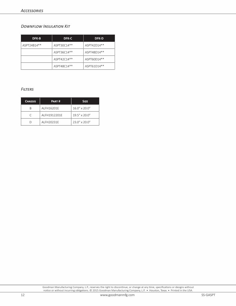
Accessories
Downflow Insulation Kit
DFK-B DFK-C DFK-D
ASPT24B14** ASPT30C14** ASPT42D14**
ASPT36C14** ASPT48D14**
ASPT42C14** ASPT60D14**
ASPT48C14** ASPT61D14**
Filters
Chassis Part # Size
B ALFH16201E 16.0” x 20.0”
C ALFH1912201E 19.5” x 20.0”
D ALFH20231E 23.0” x 20.0”