asphalt mixing plants - aapa q · plant recycling of asphalt may be by using either hot or cold...
TRANSCRIPT
Asphalt Mixing Plants
Australian Asphalt Pavement Association – 2010 1
ASPHALT MIXING PLANTS
1 INTRODUCTION These are notes are based on excerpts from the Austroads Asphalt Guide. For further information users should refer to the complete Asphalt Guide and other referenced documents.
The primary functions of an asphalt mixing plant are to: dry and heat the aggregate combine the aggregates, filler and binder in the correct proportions mix binder and aggregates discharge the mix in good condition for transport, placing and compaction.
The methods of production should: supply a homogeneous, consistent product limit segregation of the asphalt and loss of materials meet required environmental standards for emissions and site management be conducted in a safe manner.
2 TYPES OF MIXING PLANTS
2.1 GENERAL Mixing plants are generally categorised as: batch plants, which produce a series of batches of asphalt continuous mixing plants (these are generally of the drum mixing type), which produce a
continuous flow of asphalt.
This categorisation reflects not only the mode of production, but also highlights different quality control needs.
Plants may be used and/or modified to cater for the production of asphalt mixes using recycled asphalt. A number of variations of both batch and continuous drum mixing plants have been developed for recycling (see Section 6).
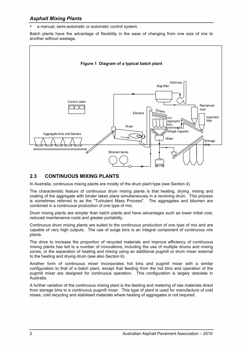
2.2 BATCH PLANTS In these plants, the aggregates and binder are weighed separately and mixed together in predetermined batch sizes in a pugmill mixing chamber.
The components of a batch plant (as shown in Figure 1) are: cold aggregate bins fitted with feeders to meter the aggregate onto a belt conveyor a cold elevator or conveyor a rotating steel drum dryer a hot elevator screens to separate the hot aggregate into various fractions a number of bins to hold hot aggregate a filler storage bin and feeder system binder storage tanks and feeding system a weigh batching system a pugmill mixer a dust collection system
Asphalt Mixing Plants
2 Australian Asphalt Pavement Association – 2010
a manual, semi-automatic or automatic control system.
Batch plants have the advantage of flexibility in the ease of changing from one size of mix to another without wastage.
Figure 1 Diagram of a typical batch plant
2.3 CONTINUOUS MIXING PLANTS In Australia, continuous mixing plants are mostly of the drum plant type (see Section 4).
The characteristic feature of continuous drum mixing plants is that heating, drying, mixing and coating of the aggregate with binder takes place simultaneously in a revolving drum. This process is sometimes referred to as the "Turbulent Mass Process". The aggregates and bitumen are combined in a continuous production of one type of mix.
Drum mixing plants are simpler than batch plants and have advantages such as lower initial cost, reduced maintenance costs and greater portability.
Continuous drum mixing plants are suited to the continuous production of one type of mix and are capable of very high outputs. The use of surge bins is an integral component of continuous mix plants.
The drive to increase the proportion of recycled materials and improve efficiency of continuous mixing plants has led to a number of innovations, including the use of multiple drums and mixing zones, or the separation of heating and mixing using an additional pugmill or drum mixer external to the heating and drying drum (see also Section 6).
Another form of continuous mixer incorporates hot bins and pugmill mixer with a similar configuration to that of a batch plant, except that feeding from the hot bins and operation of the pugmill mixer are designed for continuous operation. This configuration is largely obsolete in Australia.
A further variation of the continuous mixing plant is the feeding and metering of raw materials direct from storage bins to a continuous pugmill mixer. This type of plant is used for manufacture of cold mixes, cold recycling and stabilised materials where heating of aggregates is not required.
Aggregate bins and feeders
Storage silos
Mixer
Dryer
ElevatorScreen
Importedfiller
Bag filterChimney
Reclaimed dust
Hot aggregate bins
Weigh hoppers
Control cabin
Bitumen tanks
Asphalt Mixing Plants
Australian Asphalt Pavement Association – 2010 3
3 BATCH MIXING PROCESS In the batch plant process, aggregates are fed from cold storage bins in controlled amounts and passed through a rotating dryer, where they are dried and heated to approximately 170°C (although this temperature depends on the distance and transport time to the job and the type of binder being used). This aggregate is elevated to a screen deck, where it is separated into different sized fractions and deposited into hot storage bins. The aggregate, mineral filler and binder are then proportioned by weight, in accordance with the mix design, and thoroughly mixed in a pugmill mixing chamber. Finally, the mix is either discharged directly into trucks, or into a skip hoist or slat conveyor for transfer to hot storage.
Batch plants are rated on their mixer capacity and are generally 350 kg to 7000 kg. The actual production capacity of the plant depends on a combination of factors, including: moisture content of the aggregate capacity of the dryer screening capacity length of mixing and discharge cycles hot bin storage capacity and/or availability of trucks.
Under normal conditions, a 1,500 kg plant has a production capacity of about 70 to 90 tonnes of asphalt per hour. A 3,000 kg plant is capable of producing about 170 to 180 tonnes of asphalt per hour depending on the mix cycle time.
4 CONTINUOUS DRUM MIXING PLANTS Continuous mixing in drum plants differs from batch plants in that the aggregate is dried, heated and mixed with the binder in the one operation, eliminating the need for: hot elevator vibrating screens hot aggregate storage bins weigh hopper pugmill.
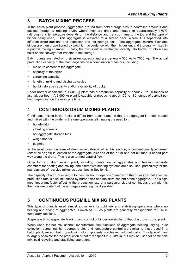
In the most common form of drum mixer, described in this section, a conventional type burner (either oil or gas) is located at the aggregate inlet end of the drum and hot bitumen is added part way along the drum. This is also termed parallel flow.
Other forms of drum mixing plant, including counterflow of aggregates and heating, separate chambers for heating and mixing, and alternative heating systems are also used, particularly for the manufacture of recycled mixes as described in Section 6.
The capacity of a drum mixer, in tonnes per hour, depends primarily on the drum size, but effective production rate is also influenced by burner size and moisture content of the aggregate. The single most important factor affecting the production rate of a particular size of continuous drum plant is the moisture content of the aggregate entering the dryer drum.
5 CONTINUOUS PUGMILL MIXING PLANTS This type of plant is used almost exclusively for cold mix and stabilising operations where no heating and drying of aggregates is involved. Such plants are generally transportable for use in temporary locations.
Aggregate bins, aggregate feeding, and control of binder are similar to that of a drum mixing plant.
When used for hot mix asphalt manufacture, the functions of aggregate heating, drying, dust collection, screening, hot aggregate bins and temperature control are similar to those used in a batch plant, except that proportioning of components is achieved volumetrically. This type of plant is largely obsolete for the production of hot mix asphalt in Australia, but may be used for some cold mix, cold recycling and stabilising operations.
Asphalt Mixing Plants
4 Australian Asphalt Pavement Association – 2010
Figure 2 Diagram of a typical drum mix plant
6 PLANT RECYCLING OF ASPHALT
6.1 GENERAL Plant recycling of asphalt may be by using either hot or cold processes. A detailed account of all asphalt recycling methods may be found in the Austroads Guide to Asphalt Recycling (1997). Insitu recycling of asphalt is also referred to in a separate topic.
The mixing process for incorporating RAP into asphalt mixes in batch mixing plants involves heat transfer from superheated aggregates. Practical considerations generally limit the proportion of RAP that can be recycled by this method to about 30% of the total mix.
The manufacturing process for drum mixing plants requires shielding or separation of the RAP from direct exposure to the burner flame.
A number of modified drum mixing plants have been developed that have proved to be more efficient than batch plants in enabling the use of much higher proportions of RAP. Modifications include: conventional drum mix plant with split feed of materials counterflow mixer with extended burner to shield RAP from direct contact with burner flame use of internal drum(s) to separate heating and mixing processes tandem drum mixers to separate heating and mixing processes indirect heating systems microwave heating.
6.2 STOCKPILING AND HANDLING OF RAP Incoming RAP materials generally require crushing and/or screening to remove oversize materials, to ensure a consistent grading and to provide a free flowing product. Separation into different sized fractions further assists control of combined grading of the asphalt mix.
Materials should be inspected or tested for contamination and suitability for recycling. Generally, materials containing crumb rubber, polymers or tar are not suitable due to the risk of fuming. Aggregates that are rounded or polished may only be suitable for base course applications.
Stockpiles of RAP should be carefully controlled to: identify and keep separate, different quality or sizes of RAP materials avoid consolidation of large stockpiles avoid moisture retention.
Bitumen tanksAggregate bins and feeders
Bag filter
ChimneyRecycled materials (RAP)
Weigher
Burner
Storage silos
Fillersilo
Mixing drum
PumpMeter
Asphalt Mixing Plants
Australian Asphalt Pavement Association – 2010 5
RAP materials can retain a great deal of moisture and undercover storage can reduce subsequent heating and drying costs.
6.3 HOT RECYCLING IN BATCH PLANTS RAP is generally transferred via a cold feed bin and weigh hopper so that it enters the pugmill at ambient temperature.
Alternatively, RAP may be added to aggregates at discharge from the dryer. This provides for more efficient heat transfer during retention in hot bins, although clogging of screens can be a problem that requires regular inspection and cleaning.
The new materials are dried, heated, screened and conveyed to the hot bins in the usual manner, except that aggregates are heated to higher than normal temperatures to provide for heat transfer to the RAP.
Heat is transferred from the superheated aggregates to the RAP in the hot bins or pugmill. The heat transfer should be sufficient to soften the binder in the RAP to allow thorough mixing of the RAP and the new material.
The temperature to which the new aggregate must be heated depends on a number of factors, including: the percentage of RAP added the temperature of the RAP the moisture content of the RAP the desired temperature of the recycled mix.
The rate of heat transfer must be closely controlled so as to avoid evaporation of light oil fractions of the binder film, which would be discharged into either the bag-house or to the atmosphere. In addition, exhaust gases with high temperatures (over 230°C) can cause further oxidation and hardening of the RAP binder as well as deterioration of the fabric bags in a bag-house dust collector.
Complete temperature equilibrium in the hot recycled mixture is usually not attained until some time after the mix has been discharged from the pugmill. Hot asphalt storage bins help in this respect.
A homogeneous mix is only achieved using this method if the duration of the mixing cycle and the proportion of RAP in the total mix are tightly controlled. The longer the mixing time, the higher the proportion of RAP that may be used. It is usual to increase the mixing time by 5 to 20 seconds and to limit the proportion of RAP to about 30% (maximum) of the total mix.
6.4 HOT RECYCLING IN DRUM MIXING PLANTS 6.4.1 Drum mixing plant with split feed
This is the most common method of hot recycling using a drum mixing plant. It consists of a multi-feed system with separate inlets for new materials and RAP. RAP is fed into the drum part way along the drum using a special collar (see Figure 2).
Drum flight systems should be modified to ensure that the virgin aggregate forms a shield between the flame and the RAP, preventing overheating.
The system has the flexibility to change from virgin materials to a blend of RAP without a loss of time or sacrificing the quality of the mix. 6.4.2 Counterflow mixer
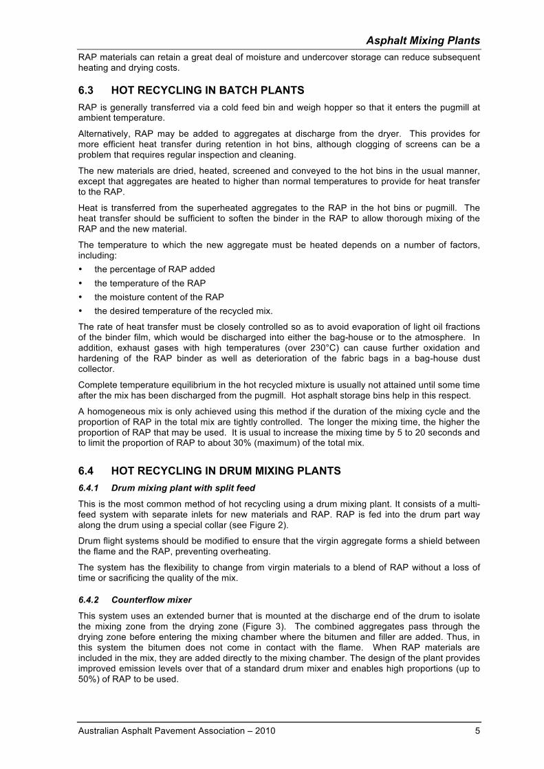
This system uses an extended burner that is mounted at the discharge end of the drum to isolate the mixing zone from the drying zone (Figure 3). The combined aggregates pass through the drying zone before entering the mixing chamber where the bitumen and filler are added. Thus, in this system the bitumen does not come in contact with the flame. When RAP materials are included in the mix, they are added directly to the mixing chamber. The design of the plant provides improved emission levels over that of a standard drum mixer and enables high proportions (up to 50%) of RAP to be used.
Asphalt Mixing Plants
6 Australian Asphalt Pavement Association – 2010
Figure 3 Counterflow drum mixer
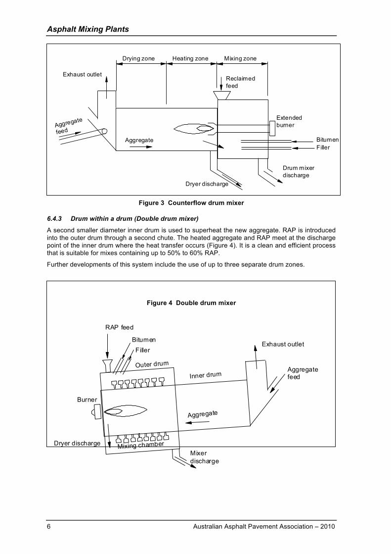
6.4.3 Drum within a drum (Double drum mixer)
A second smaller diameter inner drum is used to superheat the new aggregate. RAP is introduced into the outer drum through a second chute. The heated aggregate and RAP meet at the discharge point of the inner drum where the heat transfer occurs (Figure 4). It is a clean and efficient process that is suitable for mixes containing up to 50% to 60% RAP.
Further developments of this system include the use of up to three separate drum zones.
Figure 4 Double drum mixer
Mixer discharge
Exhaust outlet
Aggregate feed
Dryer discharge
RAP feed
FillerBitumen
Aggregate
Inner drumOuter drum
Mixing chamber
Burner
Aggregate
Drum mixer discharge
Extendedburner
Dryer discharge
BitumenFiller
Exhaust outletReclaimed feed
Drying zone Heating zone Mixing zone
Aggregate
feed
Asphalt Mixing Plants
Australian Asphalt Pavement Association – 2010 7
6.4.4 Tandem drum mixers
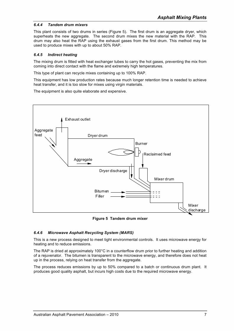
This plant consists of two drums in series (Figure 5). The first drum is an aggregate dryer, which superheats the new aggregate. The second drum mixes the new material with the RAP. This drum may also heat the RAP using the exhaust gases from the first drum. This method may be used to produce mixes with up to about 50% RAP. 6.4.5 Indirect heating
The mixing drum is fitted with heat exchanger tubes to carry the hot gases, preventing the mix from coming into direct contact with the flame and extremely high temperatures.
This type of plant can recycle mixes containing up to 100% RAP.
This equipment has low production rates because much longer retention time is needed to achieve heat transfer, and it is too slow for mixes using virgin materials.
The equipment is also quite elaborate and expensive.
Figure 5 Tandem drum mixer 6.4.6 Microwave Asphalt Recycling System (MARS)
This is a new process designed to meet tight environmental controls. It uses microwave energy for heating and to reduce emissions.
The RAP is dried at approximately 100°C in a counterflow drum prior to further heating and addition of a rejuvenator. The bitumen is transparent to the microwave energy, and therefore does not heat up in the process, relying on heat transfer from the aggregate.
The process reduces emissions by up to 50% compared to a batch or continuous drum plant. It produces good quality asphalt, but incurs high costs due to the required microwave energy.
Reclaimed feed
Burner
Mixer discharge
Exhaust outlet
Aggregate
Aggregate feed
Dryer discharge
BitumenFiller
Dryer drum
Mixer drum
Asphalt Mixing Plants
8 Australian Asphalt Pavement Association – 2010
6.5 COLD PLANT RECYCLING Cold recycling is a process in which the reclaimed asphalt pavement (RAP) is mixed with a rejuvenating agent or binder to produce cold mix asphalt. The binder can be bitumen emulsion or foamed bitumen.
Cold asphalt recycling can be done as a plant mix using RAP or in-situ by milling and adding a rejuvenating/stabilising agent. It is generally applicable to roads with low to moderate traffic volumes.
Physical properties of cold recycled asphalt typically lie between hot mix asphalt and cold bitumen stabilised material.
Cold recycling can be carried out as: Cold recycling at a central plant Cold in-situ recycling with a single unit Cold in-situ recycling with a recycling train.
As moisture is introduced to the recycled mix as part of the bitumen emulsion rejuvenating agent, it is critical to the long-term performance of cold recycled mix that this moisture is eliminated during the compaction and curing of the finished mix. This means that the mix gains strength slowly. To accelerate this stiffening process, mobile surface heating units have been used successfully.
Cold recycling can be used for deep strength and full depth applications, as well as for recycling of asphalt wearing surfaces.
A cold recycling plant may be either a batch or continuous drum plant.
In environmental and efficiency terms, a cold recycling asphalt plant provides a number of advantages, including: no heating is required high production rates can be achieved mixes with up to 100% RAP can be produced.
Both batch and continuous drum plants may be used for cold asphalt recycling, although the latter is more common.
7 COLDMIX Coldmix can be produced in a range of mixes from open to dense gradings, although a semi-dense grading generally gives the best performance.
Coldmix (or premix) is produced in a similar manner to hot mixed asphalt. It is commonly manufactured at about 100°C using bitumen that is fluxed with up to approximately 20% of cutter oil or flux oil to produce mixes which are workable at ambient temperatures.
Mixes may also be produced with bitumen emulsion binders, in which case no heating is necessary. Stockpile mixtures are made with a slow-setting cationic emulsion containing an oil distillate, to improve storage life and maintain workability when stockpiled. Coldmix may be designed and manufactured to be kept in stockpiles for several months, or supplied in bags or pails as well as in bulk.
8 ASPHALT SURGE AND STORAGE BINS Surge bins are used for the temporary retention of asphalt (generally from a few minutes to a few hours).
The advantages of surge bins are: the plant can be operated more economically by producing at a continuous steady rate fluctuations in demand can be evened out and overall production increased truck loading is much faster, so there is less waiting time quantities of asphalt can be stored for delivery outside normal plant operating hours.
Surge bins can be of any capacity from 10 tonnes to 400 tonnes. The bins are usually insulated and do not require heating, except in the vicinity of the discharge gate.
Asphalt Mixing Plants
Australian Asphalt Pavement Association – 2010 9
Storage bins are used for holding asphalt for longer periods, which under controlled conditions may be up to 48 hours, but generally not more than 24 hours. Bins for extended storage usually require heating as well as insulation. Silicone may be added to the binder to reduce hardening and an inert atmosphere may be introduced into the bin to exclude oxygen.
The allowable storage time in heated storage bins depends on mix type and binder type. Generally, mixes containing PMB binders, or high binder contents subject to binder drain (i.e. OGA and SMA) should not be stored for extended periods.
Surge and storage bins are a potential source of segregation in asphalt. Particular points requiring care include the charging of bins using batching devices or rotating chutes, the dimensions and operating range of asphalt within the bin, and operation of discharge gates when loading delivery trucks. Bins must be designed and operated correctly to minimise or avoid segregation.
9 PROCESS CONTROL
9.1 GENERAL A mixture of control of inputs, operating processes and product testing is used to control quality of asphalt.
Process control is inexorably linked with provision of assurance to the purchaser that the quality of component materials complies with the standards specified, and that the manufactured asphalt is in accordance with the designated job mix design.
The manufacturer should not, however, rely solely on the sampling and testing done for assurance and inspection purposes (see also Chapter 9) as the measures of process quality control.
Elements of process control include: Testing of raw materials Control, monitoring and testing of production process Testing of manufactured product.
A valuable tool in monitoring of production process is statistical process control. Statistical monitoring can be used as an aid to:
(a) ensuring that the asphalt meets the specified mix properties;
(b) ensuring the uniformity of the mix;
(c) detecting at an early stage any real variations in the process or the product and allow adequate corrective measures to be taken to minimise potential non-compliance of the end product; and
(d) Identifying and monitoring periods of consistent production that can be used as a basis for continuous improvement of the process.
9.2 TESTS ON RAW MATERIALS These tests should be carried out on a routine basis. The frequency of sampling and testing will depend on the nature of the production operation. For a job using a portable plant in a remote location, the checking of raw materials may need to be more frequent than an established plant using raw materials from known sources or with a process known to be under control.
9.2.1 Cold Aggregate Feeds
The grading of each aggregate should be checked frequently. Properties such as abrasion resistance, soundness, particle shape, etc., should be checked against the specification requirements at a frequency great enough to ensure compliance. Monitoring of moisture content of aggregates is important in continuous mix plants to maintain correct proportions of aggregates and binder.
Asphalt Mixing Plants
10 Australian Asphalt Pavement Association – 2010
9.2.2 Mineral Filler
If testing is carried out at the point of production and a certificate of compliance with the specification is used, then occasional checks on grading and specific gravity may be all that is necessary.
Recovered baghouse filler should also be checked periodically.
9.2.3 Binder
Tests are generally performed at the refinery on production batches to ensure conformance with the specification. Spot checks may be necessary for assurance purposes to ensure that binders have not deteriorated or been contaminated in transport and storage.
9.3 CONTROL, MONITORING AND TESTING OF PRODUCTION PROCESS 9.3.1 Cold Aggregate Feeders
The rate of feed of the various cold aggregates should be checked and adjusted as necessary to ensure the right proportions are maintained. Feed stoppages or variability must be avoided and a watch kept on fine aggregates for "arching" or "funnelling" in bins.
9.3.2 Cold Aggregate Feeder Weighing Devices
These should be regularly calibrated and checked for faults or interference. These devices are often very sensitive and should be treated accordingly.
9.3.3 Drum/Dryer Mixer
The condition of drum flights should be checked regularly as part of plant maintenance along with the functioning of the burner. Check the temperature and moisture content of aggregates/mix after drying/mixing.
9.3.4 Screens and Hot Bins
Check screens for wear and excessive or irregular carry-over. Hot bin level indicators should be cleaned and adjusted as necessary. Hot bin sample gradings performed on a regular basis will indicate problems with the screens.
9.3.5 Batch Weighing Hoppers
Periodically, test weights should be applied to the weigh hoppers to ensure accuracy.
9.3.6 Batching and Mixing
Regular checks should be performed to cover the weighing or measuring, mixing times, efficiency of the mixing, and temperature of the mix.
In addition to controlling and testing of production, visual checks should be made to pick up any problems such as unevenly mixed materials, high temperature, moisture, binder content, etc.
Items to be observed in visual inspection include: unevenly mixed or poorly coated particles evidence of excessive moisture seen as a dull brown appearance, slumping and a distinct
"crackling" sound evidence of overheating seen as blue smoke or fuming from the asphalt mix. evidence of inadequate temperature seen as a stiff appearance of the mix evidence of excessive binder – batch flattens out in truck evidence of too little binder – mix with lean, granular appearance, tending to dull brown colour evidence of excess coarse or excess fine aggregate segregation from storage bins or loading.
Asphalt Mixing Plants
Australian Asphalt Pavement Association – 2010 11
9.4 SAMPLING AND TESTING Asphalt should be sampled in accordance with AS 2891.1 and at the minimum frequency required by contract specifications or supplier’s quality plan.
Representative sampling is important. Obviously, test results from a poor sample will not be a good indicator of the properties of the mix being produced.
Compliance with the job mix is generally assessed in terms of grading and binder content. In some cases, samples taken from production may also be compacted to monitor and verify volumetric properties of the manufactured product.
Testing for grading and binder content may be determined using solvent extraction (AS 2891.3.1, 2891.3.2 or 2891.3.3) or ignition oven (AST 04).
The ignition oven is a relatively recent innovation. A high temperature furnace is used to incinerate the binder under controlled conditions, thus giving a direct measure of binder content. Grading analysis is then performed on the remaining aggregates (AS1141.11). Use of the ignition oven substantially reduces the hazards and costs associated with the use of solvents in asphalt laboratories.
Maximum density of a loose sample of manufactured asphalt (AS 2891.7.1, 2891.7.2 or 2891.7.3) may also be used as an aid to process control. It is a relatively simple test that provides an indicator of variation in binder content through change in density of the mixture, thus reducing the need for full analysis of the mixture and allowing a reduction in the frequency of full analysis.
Nuclear devices have also been used for rapid assessment of binder content. These do not reduce the need to use solvents to remove binder for grading analysis and hence are less attractive than the ignition oven.
9.5 STATISTICAL PROCESS CONTROL The use of statistical process control measures are strongly encouraged as a means of reducing the uncertainties associated with interpretation of test results from single samples.
A guide to statistical process control systems is provided in AAPA Implementation Guide IG−3: Asphalt Plant Process Control Guide.
A typical statistical process control system utilises control charts and action guidelines for interpretation of charts.
Control charts are graphical devices that highlight the average performance of data series and the dispersion around this average, of each process that is required to be monitored.
Control charts are developed from a series of samples taken from the manufacturing process. As samples can never be more than a spot check, the value of control charts lies in the ability to analyse the results of a number of samples over a period of time.
This enables relatively small changes in production that occur with time to be monitored and a cumulative impression of the effective control or otherwise of the process can be gained.
Control charts incorporate the use of upper and lower ‘Action Limits’ (also termed Control Limits) and ‘Warning Limits’. Results outside the ‘Action Limits’ require immediate action to prevent the process moving out of specification while ‘Warning Limits’ give a statistical indication that something significant may have changed in the process that may be beginning to become unstable.
Values obtained outside the Warning Limits may require action in the form of an increased frequency of sampling to determine whether or not the fluctuations observed are random events.
A typical control chart is illustrated in Figure 6.
The preferred practice is to establish two control charts for each parameter being monitored: a control chart for individual sample results or average of groups of samples, and a control chart for sample variability (or range).
In combination, these two charts will give a comprehensive picture of the variability of the parameter being monitored.

Asphalt Mixing Plants
12 Australian Asphalt Pavement Association – 2010
Figure 6 Typical control chart
It should be noted that the warning limits and action (or control) limits are determined from the statistical variation of the process being monitored and not the specified production tolerances. However, if the process is to be capable of consistently achieving the required tolerances, the action limits should not exceed the appropriate specification tolerances. Tolerance limits may also be plotted on charts to monitor compliance.
Typically, process control charts for monitoring asphalt production processes should include tests for grading (one sieve below mix nominal size, 2.36 mm and 0.075 mm sieves) binder content, and maximum density.
The charts should show:
(a) Actual individual sample test results plotted against the target value and specified tolerances.
(b) Five point rolling mean, with the target value, warning and action lines.
(c) Five point rolling range (the maximum of five points).
Corrective action should be taken when any of the following occur:
(a) One point lies outside the action limits
(b) Two out of three points lie outside the warning limits.
Investigation of possible assignable causes, and need for corrective action, should be undertaken if:
(a) Nine consecutive points in the rolling mean are above or below the target
(b) Six consecutive increasing points occur in the range
(c) Two out of three points lie outside the warning limits.
0 2 4 6 8 10 12 14 16 18 20 22 24 26 28 304.7
4.8
4.9
5
5.1
5.2
5.3

Asphalt Mixing Plants
Australian Asphalt Pavement Association – 2010 13
REFERENCES Australian Asphalt Pavement Association, Information Booklet IB-6, "Asphalt Recycling" Australian Asphalt Pavement Association, Implementation Guide IG-3, “Asphalt Plant Process Control Guide”, 1997 AAPA/APRG Pavement Work Tip No. 15, Asphalt Statistical Process Control AUSTROADS, “Guide to Asphalt Recycling.” 1997 AUSTROADS AGPT04B/07 : Guide to Pavement Technology - Part 4B: Asphalt Australian Standards AS 1141 Methods for sampling and testing aggregates
AS 1141.11 Particle size distribution by sieving AS 2891 Methods of sampling and testing asphalt
AS2891.1 Sampling of asphalt AS2891.3.1 Bitumen content and aggregate grading- Reflux method AS2891.3.2 Bitumen content and aggregate grading- Centrifugal extraction method AS2891.3.3 Bitumen content and aggregate grading- Pressure filter method AS2891.7.1 Determination of the maximum density of asphalt – Water displacement method AS2891.7.2 Determination of the maximum density of asphalt – Trichloroethane displacement
method AS2891.7.3 Determination of the maximum density of asphalt – Methylated spirits
displacement method Austroads Manual of Test Methods AST04 Asphalt binder content (Ignition oven method)