aspen plus simulation of biomass gasification in a steam...
TRANSCRIPT

Aspen plus simulation of biomass gasification in a steam blown dual fluidised bed
W. Doherty*,1,2, A. Reynolds1,2 and D. Kennedy1,2 1 Department of Mechanical Engineering, Dublin Institute of Technology, Bolton Street, Dublin 1, Ireland 2 Dublin Energy Lab, Focas Institute, Dublin Institute of Technology, Dublin 8, Ireland
The efficient utilisation of biomass resources is of utmost importance. Biomass gasification offers much higher efficiencies than combustion. Gasification is a process in which a fuel is converted to a combustible gas (syngas). A dual fluidised bed gasifier known as the fast internally circulating fluidised bed (FICFB) was selected. It has been demonstrated at industrial scale and data is readily available for model validation. An Aspen Plus model was developed to simulate the FICFB gasifier. The model is based on Gibbs free energy minimisation and the restricted equilibrium method was used to calibrate it. The model has been validated and predicts syngas composition, heating value and cold gas efficiency (CGE) in very good agreement with published data. Important operating parameters such as gasification temperature (Tg), biomass moisture, steam to biomass ratio (STBR), air-fuel ratio and air and steam temperature were varied. Tg and STBR were found to have very strong influence on syngas composition and heating value. Biomass moisture had the most significant impact on CGE. The other parameters, although less important, were found to have substantial effect on CGE.
Keywords: biomass gasification; dual fluidised bed; aspen plus; modelling; simulation; sensitivity analyses
1. Introduction
The efficient utilisation of biomass resources is of utmost importance if renewable energy is to replace a significant proportion of fossil fuels. Traditional biomass combustion based technologies achieve low electrical efficiencies (20-25%) and therefore cannot compete with fossil fuels. Biomass gasification coupled with advanced power generation systems such as gas turbines or fuel cells offer much higher efficiencies. This technology can help satisfy many EU objectives, including increasing the contribution of renewable energy, improving energy efficiency, increasing security of supply (indigenous resource), raising the level of combined heat and power (CHP) and reduction of greenhouse gas emissions. Gasification is a thermochemical process in which a carbonaceous fuel is converted to a combustible gas. This combustible gas is known as syngas (from synthetic or synthesis gas) and consists of hydrogen (H2), carbon monoxide (CO), methane (CH4), carbon dioxide (CO2), water vapour (H2O), nitrogen (N2), higher hydrocarbons and impurities such as tars, ammonia (NH3), hydrogen sulphide (H2S) and hydrogen chloride (HCl). The process occurs when a controlled amount of oxidant (pure oxygen, air, steam) is reacted at high temperatures with available carbon in the fuel within a gasifier. Steam gasification of biomass can be represented by the chemical reactions Eq. (1)-(5) in Table 1. Equations (1)-(5) are regarded as the main gasification reactions and hence are the ones considered in this work [1-4]. In addition to the reactions in Table 1, combustion reactions will occur, but these are omitted as Aspen Plus can generate them automatically and they depend on the composition of the fuel. The gasification process may be split into steps: drying (at 100-200 °C), pyrolysis (at 200-500 °C), gasification and combustion. These steps are frequently modelled in series but there is no sharp boundary dividing them and they often overlap [5]. Combustion is necessary to supply the heat required for the endothermic gasification reactions. The pyrolysis step produces char, H2, CO, CH4, CO2, H2O, tars and hydrocarbons. Pyrolysis is difficult to model and is a source of high uncertainty [1]. The three main types of gasifier include: moving/fixed bed, fluidised bed and entrained flow. Updraft fixed bed gasifiers produce syngas with very high tar content and downdraft fixed beds although attractive for biomass conversion are only suitable for small scale. Entrained flow gasifiers require a pulverised feed making them unsuitable for biomass gasification without extensive pre-treatment of the fuel, such as torrefaction or pyrolysis. Fluidised bed gasifiers are well suited to biomass conversion due to their high fuel flexibility and scale (low MW to 100 MW). A subcategory is the steam blown dual fluidised bed (DFB) gasifier. DFB gasifiers produce high quality syngas (high heating value and N2 free) and a number of different designs are in development. The fast internally circulating fluidised bed (FICFB) gasifier was selected for this study [6]. It has been successfully demonstrated at industrial scale (8 MW fuel input) and performance data is readily available for model validation. The aim of this work was to develop a model of the FICFB gasifier, to validate it against actual plant data and utilise it to examine the influence of the main operating parameters on gasifier performance. Building on previous research [7, 8], an Aspen Plus model was developed to simulate the FICFB gasifier. The model is based on Gibbs free energy minimisation and the restricted equilibrium method was used to calibrate it against published data. This was achieved by specifying the temperature approach for a number of the gasification reactions.
Materials and processes for energy: communicating current research and technological developments (A. Méndez-Vilas, Ed.)____________________________________________________________________________________________________
©FORMATEX 2013212

Table 1 Gasification reactions specified in model.
Heterogeneous reactions Eq. Homogeneous reactions Eq. NH3, H2S and HCl formation reactions Eq.
C + 2H2 ↔ CH4 (1) CH4 + H2O ↔ CO + 3H2 (4) 0.5N2 + 1.5H2 ↔ NH3 (6) C + H2O ↔ CO + H2 (2) CO + H2O ↔ CO2 + H2 (5) H2 + S ↔ H2S (7) C + CO2 ↔ 2CO (3) Cl2 + H2 ↔ 2HCl (8)
2. Technology description and DFB simulation literature review
2.1 Technology description
A DFB gasifier is based on the principle that separation of the gasification and combustion zones (GZ and CZ) will avoid N2 dilution of the syngas (due to combustion of fuel with air) and thus a high quality gas will be produced without the need for an expensive air separation unit, which would be required for O2 blown gasification. Examples of these gasifiers include: the Pyrox DFB, Silvagas DFB, MILENA and FICFB (selected for this study). The reader is referred to Corella et al. [9] and Göransson et al. [10] for a detailed review of the various DFB gasifier technologies. The FICFB technology has been under development since the early 1990s at TU Wien and has been successfully demonstrated at industrial scale (8 MW fuel input) in Güssing (Austria) since 2002 [6]. For a detailed description of the Güssing plant see Doherty et al. [11]. The fundamental idea of this gasification system is to physically separate the gasification and combustion reactions in order to gain a largely N2 free syngas [12]. With reference to Fig. 1, the biomass fuel enters a bubbling fluidised bed reactor (GZ) where it is dried, pyrolysed and gasified with steam [13]. Residual char leaves the GZ with bed material through an inclined chute and enters a circulating fluidised bed riser (CZ) where it is combusted with air. After separation from the flue gas in a cyclone, the heated bed material flows back to the GZ via a loop seal [13]. This bed material provides the heat required to drive the endothermic steam gasification reactions which produce the syngas. The FICFB gasifier operates at atmospheric pressure. The syngas is of high quality and is characterised by low N2 content, high H2 content, low tar levels and high heating value. These favourable characteristics make the syngas suitable for many applications, including CHP using gas engines, gas turbines or fuel cells, as an intermediate product for chemical synthesis or for synthetic natural gas production [14]. In Oberwart (Austria) the second CHP plant based on the FICFB gasification technology was realised and has been operational since 2008 [2]. In addition, two more FICFB based facilities began operating recently (one located in Villach, Austria and another in Ulm, Germany) [15].
Fig. 1 FICFB gasifier schematic diagram.
Materials and processes for energy: communicating current research and technological developments (A. Méndez-Vilas, Ed.)____________________________________________________________________________________________________
©FORMATEX 2013 213

2.2 DFB simulation literature review
No Aspen Plus models of the FICFB gasifier have been found in the literature. A small number of FICFB models using other computer simulation software have been published. Computer simulation models of other DFB gasifier designs have also been developed. Kaushal et al. developed a complex one-dimensional model of the FICFB gasifier [1]. Both reaction kinetics and bed hydrodynamics were considered. The model predicted the syngas composition profile (i.e. variation in composition in the axial direction) and the results indicated that most of the biomass conversion takes place in the bottom zone of the gasifier with little change in syngas composition in the freeboard. This finding proves that zero-dimensional models, like the one developed in this work, are sufficient to simulate the FICFB process. Gassner and Maréchal presented a Belsim model of the FICFB gasifier [16]. They also applied the temperature approach method to adjust the predicted syngas composition. They investigated ways to improve the efficiency of the process and predict a ~10% increase in cold gas efficiency (CGE) if the biomass is pyrolysed before feeding to the FICFB reactor. Pröll et al. reported work on an IPSEpro model of the FICFB gasifier [13, 14]. It is described as a black box model with functional equations for parametric modelling [14]. Reaction kinetics were not considered and some empirical equations were used in the model calculations. A pure equilibrium FICFB model was developed by Schuster et al. using IPSEpro [3]. It is clear from the results of this simulation that the real FICFB process is far from equilibrium as the predicted H2 and CO contents are well above real FICFB gasifier values and CH4 and CO2 contents are well below actual levels. Two ChemCAD FICFB models have been published by an Italian research group [4, 17]. The models are based on the 500 kW FICFB pilot plant operating at the ENEA Trisaia Research Centre. The results for both models do not show good agreement with the reported syngas composition for the FICFB pilot plant. Abdelouahed et al. simulated the Silvagas and TNEE DFB gasification processes [18]. The model is a semi-kinetic Aspen Plus simulation that incorporates Fortran subroutines. A pyrolysis correlation was implemented and both tar and char were considered. Bed hydrodynamics were neglected. Jie et al. presented an Aspen Plus model of a 150 kW DFB gasifier (called the MIUN gasifier by the authors) [19]. They applied the Gibbs free energy minimisation with temperature approach method and empirical equations were used to predict the products of pyrolysis including char and tar. De Kam et al. developed a process simulation model of the Silvagas DFB gasifier using Aspen Plus [20]. The Gibbs free energy minimisation with temperature approach method was also applied by these authors. An Aspen Plus heat stream was used to simulate the transfer of heat from the gasifier CZ to the GZ via bed material. The amount of char directed to the CZ was set at 19.7%; this constraint reduces the model prediction capability. An Aspen Plus model of the Silvagas process was published by Cohce et al. [21]. The model uses National Renewable Energy Laboratory correlations to adjust the syngas composition from an Aspen Plus RGibbs reactor. From the article it is not clear if the model was validated.
3. Modelling
3.1 Model description
The Aspen Plus flowsheet of the FICFB gasifier is depicted in Fig. 2. The model is based on the following main assumptions: isothermal and steady state operation; zero-dimensional; operation at atmospheric pressure (~1 bar); ideal gases; pressure drops are neglected; char is 100% carbon (C); all fuel bound N2 is converted to NH3 [2, 3, 20, 22]; all fuel bound sulphur (S) is converted to H2S [2, 3, 20]; all fuel bound chlorine (Cl2) is converted to HCl [20]; drying and pyrolysis are instantaneous [5]; tar formation is not considered [3, 4]; a heat stream is used to simulate the heat transferred by the circulation of bed material between the gasifier CZ and GZ [19-21]; heat loss from the gasifier is neglected [18]. The Peng-Robinson equation of state with Boston-Mathias modifications was selected as the property method for the model. With reference to Fig. 2, the stream ‘BIOMASS’ was specified as a non-conventional stream and the ultimate and proximate analyses, given in Table 2, were entered. The biomass lower heating value (LHV) was also specified with the HCOALGEN and DCOALIGT property models chosen to estimate the biomass enthalpy of formation, specific heat capacity and density based on the ultimate and proximate analyses. Finally, the stream thermodynamic condition (1 bar and 25 °C) and mass flow rate were inputted. The reader should note that the pressure of all feed streams and unit operation blocks were set to 1 bar (i.e. no pressure drop in the system). The mass yields of the RYield reactor ‘BRKDOWN’, which converts the non-conventional biomass into conventional components, are determined and set using a calculator block. The outlet stream ‘ELEMENTS’ is fed to a separator block ‘CHARSEP’ whose purpose is to separate out a portion of the char (assumed 100% C) and all of the ash. The char split fraction is set using a design specification; the block split fraction is varied until the gasification temperature (Tg) of 850 °C is achieved [16, 23]. The char and ash are directed to the gasifier CZ, simulated by an RStoic reactor titled ‘COMB’.
Materials and processes for energy: communicating current research and technological developments (A. Méndez-Vilas, Ed.)____________________________________________________________________________________________________
©FORMATEX 2013214

Fig. 2 FICFB gasifier aspen plus flowsheet. The air stream ‘COMBAIR’ is also fed to this block. The mole fraction of the air was specified as 0.79 N2 and 0.21 O2 and its temperature (Ta) was set to 450 °C [24]. The air mass flow rate is computed and set using a calculator block; air mass flow rate equals biomass mass flow rate multiplied by an assumed air-fuel ratio of 1.12 [24]. The air and char react to produce the heat required for gasification, represented by the heat stream ‘QGASIF’ connecting the block ‘COMB’ to ‘GASIF’. No chemical reactions were specified; the generate combustion reactions option was selected. The combustion temperature (Tcomb) is set by a calculator block; Tcomb was assumed to be 55 °C above Tg [13]. The chosen air-fuel ratio ensures complete combustion of the char; therefore, the stream ‘TOASHSEP’ contains only CO2, O2, N2 and ash. The separator ‘ASHSEP’ simulates ash removal from the gasifier. The stream ‘TOCYCLO’ made up of CO2, O2 and N2 enters a separator titled ‘CYCLONE’ where any un-reacted char is separated out and recycled to the gasifier. The block split fraction was specified as 0.85 (typical cyclone separation efficiency). In a real FICFB gasifier entrained bed material and fly ash would also be separated from the exhaust gas and recycled but this has not been modelled. As mentioned above, at normal conditions combustion is complete; therefore, the ‘SOLIDS’ stream has zero mass flow rate. ‘FLUEGAS’ represents the final exhaust from the gasifier CZ. The material stream ‘ELEM2’ is directed to the RStoic reactor ‘NONEQUIL’ where 100% of the fuel bound N2, S and Cl2 are converted to NH3, H2S and HCl respectively via Eq. (6)-(8). The enthalpy change due to this process is accounted for by the heat stream ‘QNONEQ’ fed to ‘GASIF’. The NH3, H2S and HCl are removed from the main fuel stream using the separator ‘GASSEP’. The main fuel stream ‘ELEM3’ is fed to the gasifier GZ simulated using an RGibbs reactor named ‘GASIF’. The other feed stream is the steam needed to gasify the biomass and fluidise the bed. The steam temperature (Tsteam) was set to 450 °C and its mass flow rate depends on the gasifier steam to biomass ratio (STBR). STBR is defined as the mass flow rate of biomass moisture plus the injected steam divided by the dry biomass mass flow rate. The injected steam mass flow rate is set by a design specification block employing the wet biomass mass flow rate, the specified moisture content and a STBR of 0.75 in its calculations [23]. In the block ‘GASIF’ the gasification reactions Eq. (1)-(5) were specified with zero temperature approach for each reaction (i.e. the chemical equilibrium constant for each reaction is calculated at the reactor temperature; so the block outputs the equilibrium gas composition).
Materials and processes for energy: communicating current research and technological developments (A. Méndez-Vilas, Ed.)____________________________________________________________________________________________________
©FORMATEX 2013 215
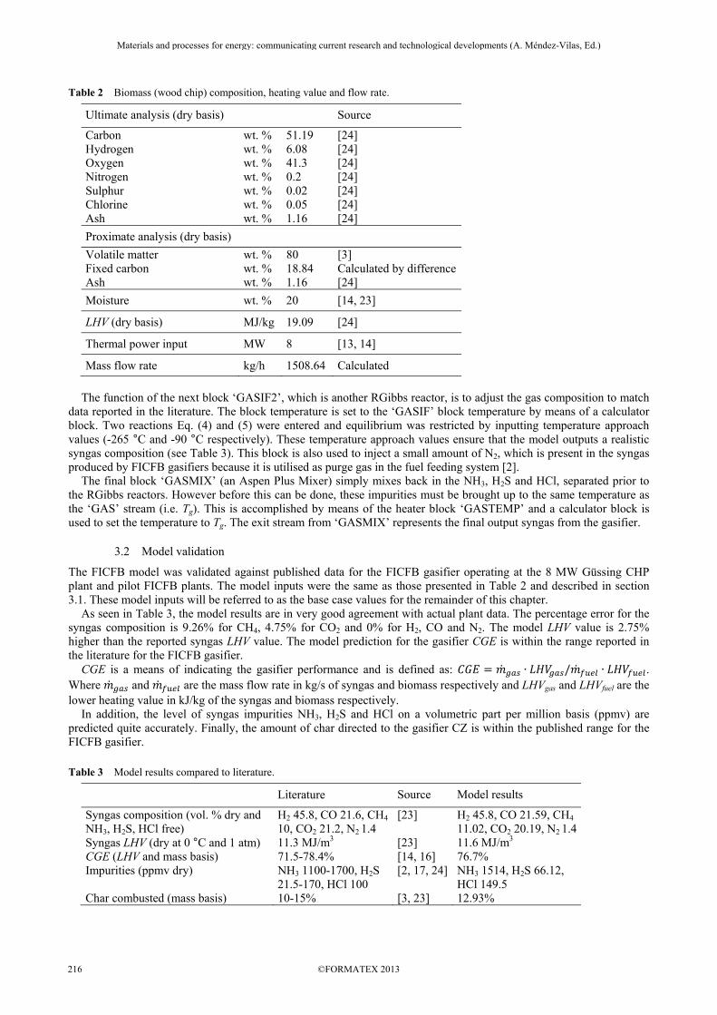
Table 2 Biomass (wood chip) composition, heating value and flow rate.
Ultimate analysis (dry basis) Source
Carbon wt. % 51.19 [24] Hydrogen wt. % 6.08 [24] Oxygen wt. % 41.3 [24] Nitrogen wt. % 0.2 [24] Sulphur wt. % 0.02 [24] Chlorine wt. % 0.05 [24] Ash wt. % 1.16 [24]
Proximate analysis (dry basis)
Volatile matter wt. % 80 [3] Fixed carbon wt. % 18.84 Calculated by differenceAsh wt. % 1.16 [24]
Moisture wt. % 20 [14, 23]
LHV (dry basis) MJ/kg 19.09 [24]
Thermal power input MW 8 [13, 14]
Mass flow rate kg/h 1508.64 Calculated
The function of the next block ‘GASIF2’, which is another RGibbs reactor, is to adjust the gas composition to match data reported in the literature. The block temperature is set to the ‘GASIF’ block temperature by means of a calculator block. Two reactions Eq. (4) and (5) were entered and equilibrium was restricted by inputting temperature approach values (-265 °C and -90 °C respectively). These temperature approach values ensure that the model outputs a realistic syngas composition (see Table 3). This block is also used to inject a small amount of N2, which is present in the syngas produced by FICFB gasifiers because it is utilised as purge gas in the fuel feeding system [2]. The final block ‘GASMIX’ (an Aspen Plus Mixer) simply mixes back in the NH3, H2S and HCl, separated prior to the RGibbs reactors. However before this can be done, these impurities must be brought up to the same temperature as the ‘GAS’ stream (i.e. Tg). This is accomplished by means of the heater block ‘GASTEMP’ and a calculator block is used to set the temperature to Tg. The exit stream from ‘GASMIX’ represents the final output syngas from the gasifier.
3.2 Model validation
The FICFB model was validated against published data for the FICFB gasifier operating at the 8 MW Güssing CHP plant and pilot FICFB plants. The model inputs were the same as those presented in Table 2 and described in section 3.1. These model inputs will be referred to as the base case values for the remainder of this chapter. As seen in Table 3, the model results are in very good agreement with actual plant data. The percentage error for the syngas composition is 9.26% for CH4, 4.75% for CO2 and 0% for H2, CO and N2. The model LHV value is 2.75% higher than the reported syngas LHV value. The model prediction for the gasifier CGE is within the range reported in the literature for the FICFB gasifier. CGE is a means of indicating the gasifier performance and is defined as: = ∙ / ∙ . Where and are the mass flow rate in kg/s of syngas and biomass respectively and LHVgas and LHVfuel are the lower heating value in kJ/kg of the syngas and biomass respectively. In addition, the level of syngas impurities NH3, H2S and HCl on a volumetric part per million basis (ppmv) are predicted quite accurately. Finally, the amount of char directed to the gasifier CZ is within the published range for the FICFB gasifier. Table 3 Model results compared to literature.
Literature Source Model results
Syngas composition (vol. % dry and NH3, H2S, HCl free)
H2 45.8, CO 21.6, CH4 10, CO2 21.2, N2 1.4
[23] H2 45.8, CO 21.59, CH4 11.02, CO2 20.19, N2 1.4
Syngas LHV (dry at 0 °C and 1 atm) 11.3 MJ/m3 [23] 11.6 MJ/m3 CGE (LHV and mass basis) 71.5-78.4% [14, 16] 76.7% Impurities (ppmv dry) NH3 1100-1700, H2S
21.5-170, HCl 100 [2, 17, 24] NH3 1514, H2S 66.12,
HCl 149.5 Char combusted (mass basis) 10-15% [3, 23] 12.93%
Materials and processes for energy: communicating current research and technological developments (A. Méndez-Vilas, Ed.)____________________________________________________________________________________________________
©FORMATEX 2013216
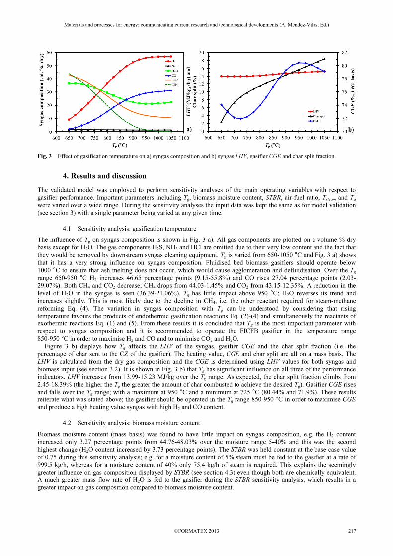
Fig. 3 Effect of gasification temperature on a) syngas composition and b) syngas LHV, gasifier CGE and char split fraction.
4. Results and discussion
The validated model was employed to perform sensitivity analyses of the main operating variables with respect to gasifier performance. Important parameters including Tg, biomass moisture content, STBR, air-fuel ratio, Tsteam and Ta were varied over a wide range. During the sensitivity analyses the input data was kept the same as for model validation (see section 3) with a single parameter being varied at any given time.
4.1 Sensitivity analysis: gasification temperature
The influence of Tg on syngas composition is shown in Fig. 3 a). All gas components are plotted on a volume % dry basis except for H2O. The gas components H2S, NH3 and HCl are omitted due to their very low content and the fact that they would be removed by downstream syngas cleaning equipment. Tg is varied from 650-1050 °C and Fig. 3 a) shows that it has a very strong influence on syngas composition. Fluidised bed biomass gasifiers should operate below 1000 °C to ensure that ash melting does not occur, which would cause agglomeration and defluidisation. Over the Tg range 650-950 °C H2 increases 46.65 percentage points (9.15-55.8%) and CO rises 27.04 percentage points (2.03-29.07%). Both CH4 and CO2 decrease; CH4 drops from 44.03-1.45% and CO2 from 43.15-12.35%. A reduction in the level of H2O in the syngas is seen (36.39-21.06%). Tg has little impact above 950 °C; H2O reverses its trend and increases slightly. This is most likely due to the decline in CH4, i.e. the other reactant required for steam-methane reforming Eq. (4). The variation in syngas composition with Tg can be understood by considering that rising temperature favours the products of endothermic gasification reactions Eq. (2)-(4) and simultaneously the reactants of exothermic reactions Eq. (1) and (5). From these results it is concluded that Tg is the most important parameter with respect to syngas composition and it is recommended to operate the FICFB gasifier in the temperature range 850-950 °C in order to maximise H2 and CO and to minimise CO2 and H2O. Figure 3 b) displays how Tg affects the LHV of the syngas, gasifier CGE and the char split fraction (i.e. the percentage of char sent to the CZ of the gasifier). The heating value, CGE and char split are all on a mass basis. The LHV is calculated from the dry gas composition and the CGE is determined using LHV values for both syngas and biomass input (see section 3.2). It is shown in Fig. 3 b) that Tg has significant influence on all three of the performance indicators. LHV increases from 13.99-15.23 MJ/kg over the Tg range. As expected, the char split fraction climbs from 2.45-18.39% (the higher the Tg the greater the amount of char combusted to achieve the desired Tg). Gasifier CGE rises and falls over the Tg range; with a maximum at 950 °C and a minimum at 725 °C (80.44% and 71.9%). These results reiterate what was stated above; the gasifier should be operated in the Tg range 850-950 °C in order to maximise CGE and produce a high heating value syngas with high H2 and CO content.
4.2 Sensitivity analysis: biomass moisture content
Biomass moisture content (mass basis) was found to have little impact on syngas composition, e.g. the H2 content increased only 3.27 percentage points from 44.76-48.03% over the moisture range 5-40% and this was the second highest change (H2O content increased by 3.73 percentage points). The STBR was held constant at the base case value of 0.75 during this sensitivity analysis; e.g. for a moisture content of 5% steam must be fed to the gasifier at a rate of 999.5 kg/h, whereas for a moisture content of 40% only 75.4 kg/h of steam is required. This explains the seemingly greater influence on gas composition displayed by STBR (see section 4.3) even though both are chemically equivalent. A much greater mass flow rate of H2O is fed to the gasifier during the STBR sensitivity analysis, which results in a greater impact on gas composition compared to biomass moisture content.
Materials and processes for energy: communicating current research and technological developments (A. Méndez-Vilas, Ed.)____________________________________________________________________________________________________
©FORMATEX 2013 217
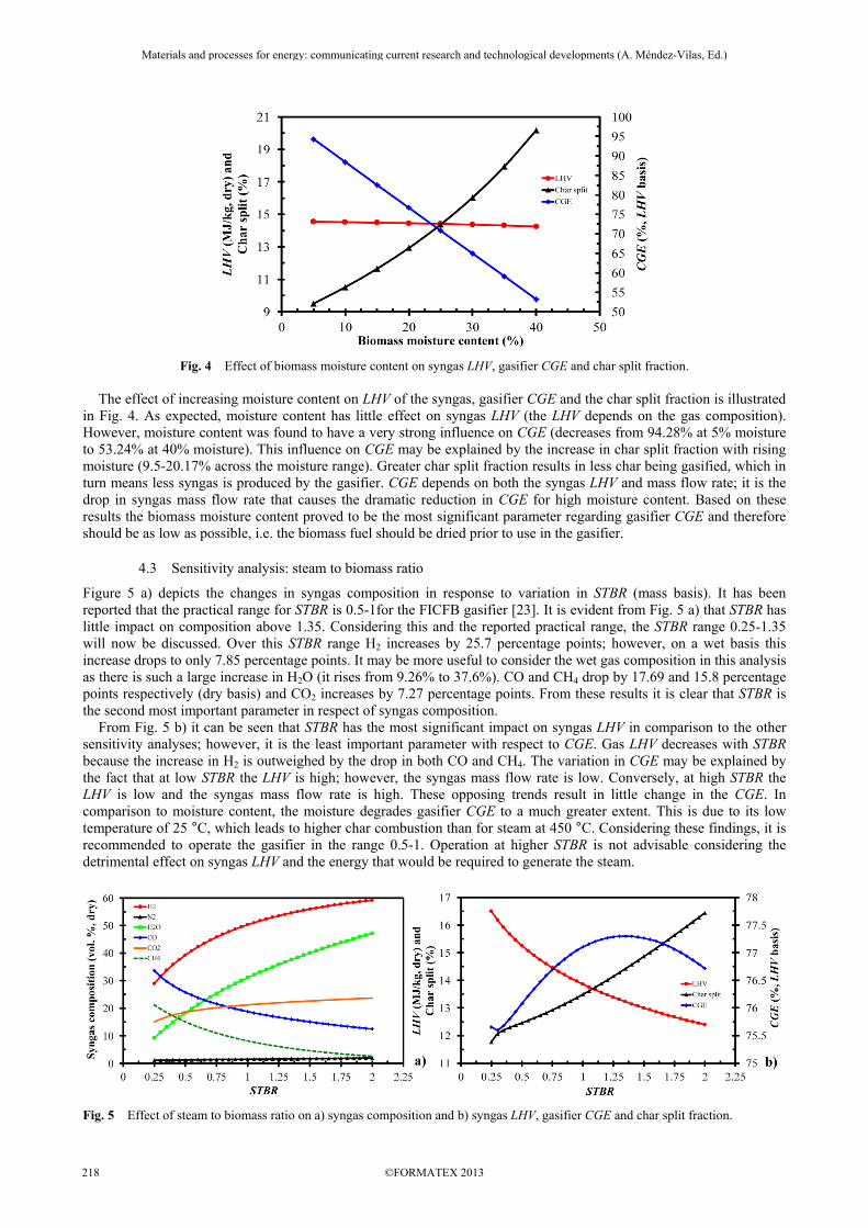
Fig. 4 Effect of biomass moisture content on syngas LHV, gasifier CGE and char split fraction. The effect of increasing moisture content on LHV of the syngas, gasifier CGE and the char split fraction is illustrated in Fig. 4. As expected, moisture content has little effect on syngas LHV (the LHV depends on the gas composition). However, moisture content was found to have a very strong influence on CGE (decreases from 94.28% at 5% moisture to 53.24% at 40% moisture). This influence on CGE may be explained by the increase in char split fraction with rising moisture (9.5-20.17% across the moisture range). Greater char split fraction results in less char being gasified, which in turn means less syngas is produced by the gasifier. CGE depends on both the syngas LHV and mass flow rate; it is the drop in syngas mass flow rate that causes the dramatic reduction in CGE for high moisture content. Based on these results the biomass moisture content proved to be the most significant parameter regarding gasifier CGE and therefore should be as low as possible, i.e. the biomass fuel should be dried prior to use in the gasifier.
4.3 Sensitivity analysis: steam to biomass ratio
Figure 5 a) depicts the changes in syngas composition in response to variation in STBR (mass basis). It has been reported that the practical range for STBR is 0.5-1for the FICFB gasifier [23]. It is evident from Fig. 5 a) that STBR has little impact on composition above 1.35. Considering this and the reported practical range, the STBR range 0.25-1.35 will now be discussed. Over this STBR range H2 increases by 25.7 percentage points; however, on a wet basis this increase drops to only 7.85 percentage points. It may be more useful to consider the wet gas composition in this analysis as there is such a large increase in H2O (it rises from 9.26% to 37.6%). CO and CH4 drop by 17.69 and 15.8 percentage points respectively (dry basis) and CO2 increases by 7.27 percentage points. From these results it is clear that STBR is the second most important parameter in respect of syngas composition. From Fig. 5 b) it can be seen that STBR has the most significant impact on syngas LHV in comparison to the other sensitivity analyses; however, it is the least important parameter with respect to CGE. Gas LHV decreases with STBR because the increase in H2 is outweighed by the drop in both CO and CH4. The variation in CGE may be explained by the fact that at low STBR the LHV is high; however, the syngas mass flow rate is low. Conversely, at high STBR the LHV is low and the syngas mass flow rate is high. These opposing trends result in little change in the CGE. In comparison to moisture content, the moisture degrades gasifier CGE to a much greater extent. This is due to its low temperature of 25 °C, which leads to higher char combustion than for steam at 450 °C. Considering these findings, it is recommended to operate the gasifier in the range 0.5-1. Operation at higher STBR is not advisable considering the detrimental effect on syngas LHV and the energy that would be required to generate the steam.
Fig. 5 Effect of steam to biomass ratio on a) syngas composition and b) syngas LHV, gasifier CGE and char split fraction.
Materials and processes for energy: communicating current research and technological developments (A. Méndez-Vilas, Ed.)____________________________________________________________________________________________________
©FORMATEX 2013218

Fig. 6 Effect of a) air-fuel ratio and b) combustion air temperature on syngas LHV, gasifier CGE and char split fraction.
4.4 Sensitivity analysis: air-fuel ratio
Syngas composition was found to have a weak dependence on air-fuel ratio (mass basis). The largest change in the combustible gases was an increase from 45.7-47% for H2. Referring to Fig. 6 a), syngas LHV remains fairly constant. There is however a substantial decrease in CGE with increasing air-fuel ratio (CGE drops 3.35 percentage points). The decline in CGE can be attributed to the increase in char sent to the gasifier CZ and the resulting reduction in syngas mass flow rate. As air-fuel ratio increases the excess air lowers the temperature of the CZ, which in turn affects Tg. In order to maintain Tg at the desired temperature more char must be burned. In conclusion, air-fuel ratio should be as low as possible but high enough to ensure complete combustion of the char.
4.5 Sensitivity analysis: steam temperature
Syngas composition and LHV remain somewhat unchanged with a rise in Tsteam (150-1000 °C). The elevated steam temperature does reduce the amount of char required in the gasifier CZ (14.25-10.16%), which has a positive effect on gasifier performance. The CGE increases from 75.66-78.87% (up 3.21 percentage points). The improvement in performance is only slight; therefore, preheating the steam to high temperature (e.g. 500-1000 °C) is not recommended considering the energy that would be required. Waste heat, where available, should be utilised for preheating purposes.
4.6 Sensitivity analysis: combustion air temperature
Preheating the combustion air from 25-1025 °C causes slight changes in syngas composition. The largest variation in the combustible gases was a drop from 46.64-44.57% for H2. This negative trend is offset by small increases in both CO and CH4. Figure 6 b) shows how syngas LHV increases due to the change in composition and how the char split fraction drops and CGE increases. The rise in CGE is substantial (5.33 percentage points) and is as a result of the drop in char split fraction. The amount of char required in the gasifier CZ is lowered with increasing Ta because the sensible heat of the air supplies a greater portion of the heat required by the gasifier. Based on these results, air preheating is more attractive than steam preheating and if waste heat is available, it should be used to increase Ta.
5. Conclusions
A computer simulation model of the FICFB gasifier was developed using Aspen Plus. The aim of the research work, which was to develop a model of the FICFB gasifier, to validate it against actual plant data and utilise it to examine the influence of the main operating parameters on gasifier performance, was achieved. The effects of varying Tg, biomass moisture content, STBR, air-fuel ratio, Tsteam and Ta were investigated, the results of which revealed the following: Tg is the most important parameter with respect to syngas composition and has significant influence on LHV and CGE; the gasifier should be operated in the Tg range 850-950 °C; biomass moisture content is the most significant parameter regarding CGE and should be as low as possible; STBR is the most important parameter in terms of LHV but is the least significant in respect of CGE; air-fuel ratio should be as low as possible while ensuring complete combustion; air preheating is more attractive than steam preheating. Future work includes integration of the FICFB gasifier model developed here with an Aspen Plus solid oxide fuel cell model [11, 25].
References [1] Kaushal P, Proell T, Hofbauer H. Application of a detailed mathematical model to the gasifier unit of the dual fluidized bed
gasification plant. Biomass and Bioenergy. 2011;35:2491-2498.
Materials and processes for energy: communicating current research and technological developments (A. Méndez-Vilas, Ed.)____________________________________________________________________________________________________
©FORMATEX 2013 219

[2] Kern S, Pfeifer C, Hofbauer H. Gasification of wood in a dual fluidized bed gasifier: Influence of fuel feeding on process performance. Chemical Engineering Science. 2013;90:284-298.
[3] Schuster G, Loffler G, Weigl K, Hofbauer H. Biomass steam gasification - an extensive parametric modeling study. Bioresource Technology. 2001;77:71-79.
[4] Molino A, Giordano G, Motola V, Fiorenza G, Nanna F, Braccio G. Electricity production by biomass steam gasification using a high efficiency technology and low environmental impact. Fuel. 2013;103:179-192.
[5] Basu P, Kaushal P. Modeling of Pyrolysis and Gasification of Biomass in Fluidized Beds: A Review. Chemical Product and Process Modeling. 2009;4:1-45.
[6] Hofbauer H, Rauch R, Bosch K, Koch R, Aichernig C. Biomass CHP Plant Güssing - A Success Story. Expert Meeting on Pyrolysis and Gasification of Biomass and Waste. Strasbourg, France; 2002.
[7] Doherty W, Reynolds A, Kennedy D. The effect of air preheating in a biomass CFB gasifier using ASPEN Plus simulation. Biomass and Bioenergy. 2009;33:1158-1167.
[8] Doherty W, Reynolds A, Kennedy D. Simulation of a Circulating Fluidised Bed Biomass Gasifier Using ASPEN Plus – A Performance Analysis. In: Ziebik A, Kolenda Z, Stanek W, editors. 21st International Conference on Efficiency, Cost, Optimization, Simulation and Environmental Impact of Energy Systems. Krakow, Poland; 2008:1241-1248.
[9] Corella J, Toledo JM, Molina G. A Review on Dual Fluidized-Bed Biomass Gasifiers. Industrial & Engineering Chemistry Research. 2007;46:6831-6839.
[10] Göransson K, Söderlind U, He J, Zhang W. Review of syngas production via biomass DFBGs. Renewable and Sustainable Energy Reviews. 2011;15:482-492.
[11] Doherty W, Reynolds A, Kennedy D. Computer simulation of a biomass gasification-solid oxide fuel cell power system using Aspen Plus. Energy. 2010;35:4545-4555.
[12] Bolhar-Nordenkampf M, Hofbauer H. Gasification demonstration plants in Austria. IV International Slovak Biomass Forum. Bratislava; 2004:227-230.
[13] Pröll T, Rauch R, Aichernig C, Hofbauer H. Fluidized Bed Steam Gasification of Solid Biomass - Performance Characteristics of an 8 MWth Combined Heat and Power Plant. International Journal of Chemical Reactor Engineering. 2007;5:1-19.
[14] Pröll T, Hofbauer H. Development and Application of a Simulation Tool for Biomass Gasification Based Processes. International Journal of Chemical Reactor Engineering. 2008;6:1-56.
[15] Kirnbauer F, Wilk V, Hofbauer H. Performance improvement of dual fluidized bed gasifiers by temperature reduction: The behavior of tar species in the product gas. Fuel. 2013;108:534-542.
[16] Gassner M, Maréchal F. Thermodynamic comparison of the FICFB and Viking gasification concepts. Energy. 2009;34:1744-1753.
[17] Fiorenza G, Canonaco J, Blasi A, Braccio G. Biomass steam gasification at the Trisaia dual fluidized bed pilot plant: experimental results and optimization analysis of process variables. Zero Emission Power Generation Workshop. Gebze, Turkey; 2007:1-15.
[18] Abdelouahed L, Authier O, Mauviel G, Corriou JP, Verdier G, Dufour A. Detailed Modeling of Biomass Gasification in Dual Fluidized Bed Reactors under Aspen Plus. Energy & Fuels. 2012;26:3840-3855.
[19] He J, Göransson K, Söderlind U, Zhang W. Simulation of biomass gasification in a dual fluidized bed gasifier. Biomass Conversion and Biorefinery. 2012;2:1-10.
[20] De Kam MJ, Vance Morey R, Tiffany DG. Biomass Integrated Gasification Combined Cycle for heat and power at ethanol plants. Energy Conversion and Management. 2009;50:1682-1690.
[21] Cohce MK, Rosen MA, Dincer I. Efficiency evaluation of a biomass gasification-based hydrogen production. International Journal of Hydrogen Energy. 2011;36:11388-11398.
[22] Wilk V, Hofbauer H. Conversion of fuel nitrogen in a dual fluidized bed steam gasifier. Fuel. 2013;106:793-801. [23] Pröll T, Rauch R, Aichernig C, Hofbauer H. Coupling of biomass steam gasification and an SOFC-gas turbine hybrid system
for highly efficient electricity generation. ASME Turbo Expo: Power for Land, Sea, and Air. Vienna, Austria; 2004. [24] Pröll T, Hofbauer H. H2 rich syngas by selective CO2 removal from biomass gasification in a dual fluidized bed system -
Process modelling approach. Fuel Processing Technology. 2008;89:1207-1217. [25] Doherty W, Reynolds A, Kennedy D. Simulation of a Tubular Solid Oxide Fuel Cell Stack Operating on Biomass Syngas Using
Aspen Plus. Journal of The Electrochemical Society. 2010;157:B975-B981.
Materials and processes for energy: communicating current research and technological developments (A. Méndez-Vilas, Ed.)____________________________________________________________________________________________________
©FORMATEX 2013220