asp electrolytes
TRANSCRIPT

Aspen Plus®
Getting Started ModelingProcesses with
Electrolytes
Version 10.2

Part Number: Aspen Plus® 10.2February 2000
Copyright (c) 1981-2000 by Aspen Technology, Inc. All rights reserved.
Aspen Plus®, Aspen Properties®, Aspen Engineering Suite, AspenTech®, ModelManager, the aspen leaf logo and Plantelligenceare trademarks or registered trademarks of Aspen Technology, Inc., Cambridge, MA.
BATCHFRAC and RATEFRAC are trademarks of Koch Engineering Company, Inc.
All other brand and product names are trademarks or registered trademarks of their respective companies.
This manual is intended as a guide to using AspenTech's software. This documentation contains AspenTech proprietary andconfidential information and may not be disclosed, used, or copied without the prior consent of AspenTech or as set forth in theapplicable license agreement. Users are solely responsible for the proper use of the software and the application of the resultsobtained.
Although AspenTech has tested the software and reviewed the documentation, the sole warranty for the software may be found inthe applicable license agreement between AspenTech and the user. ASPENTECH MAKES NO WARRANTY ORREPRESENTATION, EITHER EXPRESSED OR IMPLIED, WITH RESPECT TO THIS DOCUMENTATION, ITSQUALITY, PERFORMANCE, MERCHANTABILITY, OR FITNESS FOR A PARTICULAR PURPOSE.
CorporateAspen Technology, Inc.Ten Canal ParkCambridge, MA 02141-2201USAPhone: (617) 949-1000Fax: (617) 949-0130URL: http://www.aspentech.com
DivisionDesign, Simulation and Optimization SystemsAspen Technology, Inc.Ten Canal ParkCambridge, MA 02141-2201USAPhone: (617) 949-1000Fax: (617) 949-1030

Getting Started Modeling Processes with Electrolytes iiiVersion 10.2
ContentsAbout Getting Started Modeling Processes with Electrolytes ................................... v
Why Use Electrolyte Simulation? .................................................................................. viWhat is an Aspen Plus Electrolyte Model?.................................................................... viSessions in this Book...................................................................................................... viiUsing Backup Files ........................................................................................................ viiFor More Information ...................................................................................................viiiTechnical Support ........................................................................................................... ix
1 Modeling Electrolyte Chemistry............................................................................1-1
Electrolyte Chemistry Flowsheet ................................................................................. 1-2Starting Aspen Plus ...................................................................................................... 1-3Drawing the Graphical Simulation Flowsheet............................................................ 1-5Specifying Title, Stream Properties, and Global Options........................................... 1-7Specifying Components............................................................................................... 1-10The Electrolytes Wizard ............................................................................................. 1-12Examining Generated Chemistry .............................................................................. 1-17Selecting Electrolyte Property Models....................................................................... 1-21Entering Stream Data ................................................................................................ 1-24Specifying the Flash Block ......................................................................................... 1-25Specifying Additional Stream Properties .................................................................. 1-26Running the Simulation ............................................................................................. 1-28Examining Simulation Results................................................................................... 1-29Exiting Aspen Plus...................................................................................................... 1-32
2 Modeling a Sour Water Stripper ............................................................................2-1
Sour Water Stripper Flowsheet.................................................................................... 2-2Starting Aspen Plus ...................................................................................................... 2-3Drawing the Graphical Simulation Flowsheet............................................................ 2-5Specifying Title, Stream Properties, and Global Options........................................... 2-7Specifying Components................................................................................................. 2-9The Electrolytes Wizard ............................................................................................. 2-10Examining Generated Chemistry .............................................................................. 2-15Entering Stream Data ................................................................................................ 2-20Specifying the RadFrac Block..................................................................................... 2-22Running the Simulation ............................................................................................. 2-31Examining Simulation Results................................................................................... 2-32Converting to True Components ................................................................................ 2-38Running the True Component Simulation ................................................................ 2-41Exiting Aspen Plus...................................................................................................... 2-43

iv Getting Started Modeling Processes with ElectrolytesVersion 10.2
A Connecting to the Aspen Plus Simulation Engine............................................A-1

Getting Started Modeling Processes with Electrolytes vVersion 10.2
About Getting StartedModeling Processes withElectrolytes
You can easily model all types of electrolyte systems with Aspen Plus, includingsystems with strong electrolytes, weak electrolytes, salt precipitation, even mixedsolvents.
The two sessions in this book – Modeling Electrolyte Chemistry and Modeling aSour Water Stripper– introduce you to simulating electrolyte systems with AspenPlus by guiding you through two simulations.
Getting Started Modeling Processes with Electrolytes assumes that you have aninstalled copy of the Aspen Plus and User Interface software.

vi Getting Started Modeling Processes with ElectrolytesVersion 10.2
Why Use Electrolyte Simulation?
A rigorous treatment of electrolytes is needed to model many industrial systems.With the Aspen Plus electrolyte capabilities, you can model:
Sour water solutions. Water containing dissolved H2S, NH3, CO2, HCN,sometimes with additional solvents
Aqueous amines for gas sweetening. Water containing DGA, MEA, DEA, orMDEA for the removal of H2S and CO2
Aqueous acids or bases. HCl, HBr, H2SO4, H3PO4, HNO3, HF, NaOH, KOH,and others, in aqueous solution, sometimes with additional solvents
Salt solutions. NaCL, KCl, Na2SO4, CaSO4, CaCO3 in solution, sometimes withparticipation
What is an Aspen Plus Electrolyte Model?
In Aspen Plus, an electrolyte system is defined as one in which some of themolecular species dissociate partially or completely into ions in a liquid solvent,and/or some of the molecular species precipitate as salts. These dissociation andprecipitation reactions occur fast enough that the reactions can be considered tobe at chemical equilibrium. The liquid phase equilibrium reactions that describethis behavior are referred to as the solution chemistry. In Aspen Plus, solutionchemistry is often referred to simply as Chemistry.
Solution chemistry has a major impact on the simulation of electrolyte systems.For nonelectrolyte systems, chemical reactions generally occur only in reactors. InAspen Plus, all unit operation models can handle electrolyte reactions.
Solution chemistry also impacts physical property calculations and phaseequilibrium calculations. The presence of ions in the liquid phase causes highlynonideal thermodynamic behavior. Aspen Plus provides specializedthermodynamic models and built-in data to represent the nonideal behavior ofliquid phase components in order to get accurate results.
Getting Started Modeling Processes with Electrolytes viiVersion 10.2
Sessions in this Book
The two sessions in the book illustrate the following concepts:• Types of electrolyte components
• Solvents• Solutes• Ions• Salts
• Types of reactions in electrolyte solution chemistry• Complete dissociation• Partial dissociation (equilibrium reaction)• Salt precipitation (equilibrium reaction)
• Automatic Chemistry generation• Recommended physical property methods for electrolytes• Methods for calculating and reporting electrolyte systems
• True component approach• Apparent component approach
• Use of stream properties (Property Sets) for electrolytes
Follow the steps in Chapter To learn how to
1 Modeling Electrolyte Chemistry Define electrolyte components.Use automatic chemistry generation.Examine Chemistry data.View electrolyte databank parameters.Use the true component modeling approach.
2 Modeling a Sour Water Stripper Modify the generated Chemistry.Use the apparent component approach for electrolytes.Convert from apparent component approach to true component approach.
Using Backup Files
We recommend that you perform all sessions sequentially, because Chapter 2assumes you are familiar with the concepts presented in Chapter 1.
Aspen Plus provides backup files containing all problem specifications and resultsfor each tutorial session. You can use the backup files to check your results.

viii Getting Started Modeling Processes with ElectrolytesVersion 10.2
For More Information
Online Help Aspen Plus has a complete system of online help andcontext-sensitive prompts. The help system contains both context-sensitive helpand reference information. For more information about using Aspen Plus help,see the Aspen Plus User Guide, Chapter 3.
Aspen Plus application examples A suite of sample online Aspen Plussimulations illustrating specific processes is delivered with Aspen Plus.
Aspen Plus Installation Guide for Windows This guide provides instructions oninstallation of Aspen Plus.
Aspen Plus Getting Started Building and Running a Process Model Thistutorial includes several hands-on sessions to familiarize you with Aspen Plus.The guide takes you step-by-step to learn the full power and scope of Aspen Plus.
Aspen Plus Getting Started Modeling Processes with Electrolytes This tutorialincludes several hands-on sessions to familiarize you with simulating electrolytesystems with Aspen Plus.
Aspen Plus Getting Started Modeling Petroleum Processes This tutorialincludes several hands-on sessions to familiarize you with simulating petroleumprocesses with Aspen Plus.
Aspen Plus Getting Started Customizing Unit Operation Models This tutorialincludes several hands-on sessions to familiarize you with the customization ofunit operation models with Aspen Plus.
Aspen Plus Getting Started Modeling Processes with Solids This tutorialincludes several hands-on sessions to familiarize you with simulating systemscontaining solids with Aspen Plus.
Aspen Plus User Guide The three-volume Aspen Plus User Guide providesstep-by-step procedures for developing and using an Aspen Plus processsimulation model. The guide is task-oriented to help you accomplish theengineering work you need to do, using the powerful capabilities of Aspen Plus.

Getting Started Modeling Processes with Electrolytes ixVersion 10.2
Aspen Plus reference manual series Aspen Plus reference manuals providedetailed technical reference information. These manuals include backgroundinformation about the unit operation models and the physical properties methodsand models available in Aspen Plus, tables of Aspen Plus databank parameters,group contribution method functional groups, and a wide range of other referenceinformation. The set comprises:• Unit Operation Models
• Physical Property Methods and Models
• Physical Property Data
• User Models
• System Management
• System Administration
• Summary File Toolkit
• Input Language Guide
The Aspen Plus manuals are delivered in Adobe portable document format (PDF)on the Aspen Plus Documentation CD.
Technical Support
World Wide Web For additional information about AspenTech products andservices, check the AspenTech World Wide Web home page on the Internet at:http://www.aspentech.com/
Technical resources AspenTech customers with a valid license and softwaremaintenance agreement can register to access the Online Technical SupportCenter at http://support.aspentech.com/
This web support site allows you to:• Access current product documentation• Search for tech tips, solutions and frequently asked questions (FAQs)• Search for and download application examples• Submit and track technical issues• Send suggestions• Report product defects• Review lists of known deficiencies and defects

x Getting Started Modeling Processes with ElectrolytesVersion 10.2
Registered users can also subscribe to our Technical Support e-Bulletins. These e-Bulletins are used to proactively alert users to important technical supportinformation such as:• Technical advisories• Product updates and Service Pack announcements
The most up-to-date contact information for your nearest support office is alsoavailable on AspenTech's web page at http://support.aspentech.com/
The following contact information was current when this product was released:
If you are located in: Phone Number Fax Number E-Mail Address
North America & the Caribbean +1-617/949-1021
+1-888/996-7001 (toll free)
+1-617/949-1724 [email protected]
South America (Argentina office)
(Brazil office)
+54-11/4393-5308
+55-11/5012-0321
+54-11/4394-8621
+55-11/5012-4442
Europe, Gulf Region, & Africa (Brussels office)
(UK office)
+32-2/724-0100
+44-1223/312220
+32-2/705-4034
+44-1223/366980
Japan +81-3/3262-1743 +81-3/3262-1744 [email protected]
Asia & Australia(Singapore office)
+65/295-83-30 +65/295-83-25 [email protected]
Chapter 1
Getting Started Modeling Processes with Electrolytes 1-1Version 10.2
1 Modeling ElectrolyteChemistry
In this simulation mix and flash two feed streams containing aqueouselectrolytes.
You will:• Define electrolyte components• Use the Electrolytes Expert System• Examine Chemistry data• View electrolytes databank parameters• Use the true components modeling approach
Allow about 45 minutes to do this simulation.

ModelingElectrolyteChemistry
1-2 Getting Started Modeling Processes with ElectrolytesVersion 10.2
Electrolyte Chemistry Flowsheet
The process flow diagram and operating conditions for this simulation are shownin the process diagram below: Electrolyte Chemistry. Two feed streams, onecontaining water and HCl, the other water and NaOH, are fed to a mixer. Themixer outlet is flashed to evaporate water and cause NaCl to precipitate. Use theMIXER model for the mixer and the FLASH2 model for the flash.
MIX
MIXER
FLASH
FLASH2
HCL
NAOH
LIQUID
VAPOR
MIXED
IsobaricAdiabatic
IsobaricMolar vapor fraction = 0.75
Temp = 25 CPres = 1 bar10 kmol/hr H2O1 kmol/hr HCL
Temp = 25 CPres = 1 bar10 kmol/hr H2O1.1 kmol /hr NAOH
Electrolyte Chemistry

Chapter 1
Getting Started Modeling Processes with Electrolytes 1-3Version 10.2
Starting Aspen Plus
To start Aspen Plus:
1. From your desktop, select Start and then select Programs.
2. Select AspenTech, then Aspen Plus 10.2, then Aspen Plus User Interface.
The Aspen Plus Startup dialog box appears. Aspen Plus displays adialog box whenever you must enter information or make a selectionbefore proceeding. In this simulation, use an Aspen Plus template.
To select the Template option:
1. Select the Template radio button and click .
The New dialog box appears.
Use the New dialog box to specify the Application Type and the Run Typefor the new run. Aspen Plus uses the Application Type you choose toautomatically set various defaults appropriate to your application.

ModelingElectrolyteChemistry
1-4 Getting Started Modeling Processes with ElectrolytesVersion 10.2
To specify the Application Type and Run Type for the new run:
1. Select the Electrolytes with Metric Units template.
Note The default Run Type, Flowsheet, is appropriate for thissimulation.
2. Click to apply these options.
It takes a few seconds for Aspen Plus to apply these options.
Note If the Connect Host dialog box appears, see Appendix A.
The Aspen Plus window is now active.

Chapter 1
Getting Started Modeling Processes with Electrolytes 1-5Version 10.2
Drawing the Graphical SimulationFlowsheet
In this simulation you will begin to build the process flowsheet. Since you willenter your own block and stream IDs, turn off the default Create auto block IDand Create auto stream ID options, which provide these IDs automatically.
1. From the Aspen Plus menu bar, select Tools and then select Options.
The Options dialog box appears.
2. Select the Flowsheet tab.
3. Deselect the Automatically Assign Block Name with Prefix and the AutomaticallyAssign Stream Name with Prefix options.

ModelingElectrolyteChemistry
1-6 Getting Started Modeling Processes with ElectrolytesVersion 10.2
4. Click to close the Options dialog box and apply the changes.
The process flow diagram and simulation definition for this simulation areshown in the process diagram: Electrolyte Chemistry on page 1-2.
5. Place the flowsheet blocks and streams to create the graphical simulation flowsheetas follows:
6. Click to guide you to the next required input.
The Flowsheet Complete dialog box appears.
7. Click to continue.
Chapter 1
Getting Started Modeling Processes with Electrolytes 1-7Version 10.2
Specifying Title, Stream Properties, andGlobal Options
The Data Browser window appears. The Setup Specifications Global sheetdisplays defaults Aspen Plus uses for other sheets.
Use this sheet to give your simulation a title, and to review the stream propertiesand global options that were set when you selected the Electrolytes with MetricUnits template.
Note The Run Type field displays Flowsheet, which is appropriate forthis simulation.
It is always good practice to enter a title for the simulation.
1. In the Title field, enter Getting Started with Electrolytes - Simulation 1.
The Electrolytes with Metric Units application type sets the followingglobal defaults for electrolytes applications:• The Input data and Output results fields are populated with
METCBAR units (Metric units with temperature in degreesCentigrade and pressure in bars)
• The Flow basis field is populated with Mass for all flow inputs

ModelingElectrolyteChemistry
1-8 Getting Started Modeling Processes with ElectrolytesVersion 10.2
To specify flows on a mole basis for this simulation:
1. At the Flow basis field, click and select Mole.
Based on the Electrolytes with Metric Units template, Aspen Plusdisplays the following defaults for calculating and reporting streamproperties:• Flow and Fraction Basis of Mass: Aspen Plus will report the
component flow rates on a mass flow basis• ELEC_E Stream Sheetat: Aspen Plus sheetats the Stream Summary
sheet for electrolytes.
To review the report options specified in the selected template:
1. From the Data Browser, select the Setup Report Options sheet.
2. Select on the Stream tab.
Note You will return to this sheet and specify stream propertieslater in this simulation.

Chapter 1
Getting Started Modeling Processes with Electrolytes 1-9Version 10.2
To move to the next required input:
1. From the Data Browser, select the Components folder and then select Specifications.

ModelingElectrolyteChemistry
1-10 Getting Started Modeling Processes with ElectrolytesVersion 10.2
Specifying Components
The Components Specifications Selection sheet appears.
The apparent (or base) components for this simulation are H2O, HCL, andNaOH.
Note Because you chose an electrolytes template, water alreadyappears on the sheet.
1. Enter the remaining components (HCL and NAOH) as following:
H2O Water
HCL Hydrogen-Chloride
NAOH NAOH
To rename H20 to water:
1. In the Component ID field, select H20 and enter Water.
Chapter 1
Getting Started Modeling Processes with Electrolytes 1-11Version 10.2
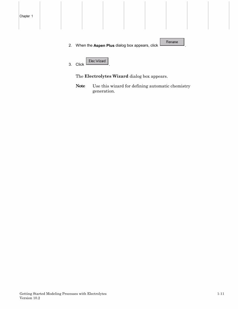
2. When the Aspen Plus dialog box appears, click .
3. Click .
The Electrolytes Wizard dialog box appears.
Note Use this wizard for defining automatic chemistrygeneration.

ModelingElectrolyteChemistry
1-12 Getting Started Modeling Processes with ElectrolytesVersion 10.2
The Electrolytes Wizard
Use the Electrolytes Wizard to define the ionic species and salts that can begenerated from the base components entered on the Components SpecificationsSelection sheet, and to generate the reactions that occur among thesecomponents in the liquid phase.
1. From the Electrolytes Wizard dialog box, click .
The Base Components and Reactions Generation Option dialog boxappears. In this dialog box, there is an option (turned off) labeledHydrogen Ion type Hydronium ion H+. Aspen Plus can treat acidic speciesas either H+ or H3O+. However, use of H3O+ is strongly recommended,because the presence of H3O+ in the solution chemistry is better able torepresent the phase and chemical equilibrium of almost all electrolytesystems.
2. Click to move all components in the Available components column to theSelected components column.

Chapter 1
Getting Started Modeling Processes with Electrolytes 1-13Version 10.2
3. Click to continue.
The Generated Species and Reactions dialog box appears:
Aspen Plus generates all possible ionic and salt species, and reactions forthe H2O-NAOH-HCL system.
In the Reactions section in the Generated Species and Reactionsdialog box, different style arrows denote the following reaction types:
<<===>> Denotes ionic equilibrium or salt precipitation
--->> Denotes complete dissociation
In this example, three types of reactions are generated: ionic equilibrium,complete dissociation, and salt precipitation.
The dissociation of water and the dissociation of HCL are equilibriumreactions. NACL precipitation/dissolution is also an equilibrium reaction.In contrast, NAOH dissociates completely and irreversibly into NA+ andOH.
4. Click to eliminate any of the generated species and reactions.
Note In this simulation, the NaOH and the NaOH*W salts arenot relevant.

ModelingElectrolyteChemistry
1-14 Getting Started Modeling Processes with ElectrolytesVersion 10.2
To remove these salts from the solution chemistry:
1. From the Salts list, select NaOH(S) and NaOH*W(S).
2. Click .
Now that you have removed these salts from the Generated AqueousSpecies list, Aspen Plus automatically removes all reactions involvingNaOH(S) and NaOH*W(S) from the Reactions list.
Note Any time you know that a reaction can be neglectedbecause of expected process conditions, remove it from thesolution chemistry to decrease the execution time requiredfor your simulation.

Chapter 1
Getting Started Modeling Processes with Electrolytes 1-15Version 10.2
3. On the Generated Species and Reactions dialog box click to acceptthe generated species and reactions.
The Simulation Approach dialog box appears, allowing you to choosebetween the true component approach and the apparent componentapproach.
4. Select the radio button next to the True component approach field.
When you use the true component approach, Aspen Plus solves theequations describing solution chemistry simultaneously with the unitoperation equations. The unit operations deal directly with the ions andsalts sheeted by solution chemistry. In addition, the true componentapproach defines how Aspen Plus reports the simulation results. Resultsare reported in terms of the ions, salts, and molecular components thatare actually present, not in terms of the original base components.
For example, the generated chemistry for this system specifies thatNAOH fully dissociates into NA+ and OH-. If you choose the truecomponent approach, Aspen Plus will report NAOH flow in terms of NA+
flow and OH- flow, not in terms of the NAOH base component flow. Youcan request that composition and flows also be reported in terms of theapparent (base) components. You will do this later in this simulation.
5. Click to move to the next dialog box.
The Summary dialog box appears, providing Aspen Plus electrolytesexpert system information.
6. Click to close the dialog box.
On the Components Specifications Selection sheet, Aspen Plus hasnow added the generated electrolyte components. Since all componentsare databank components, Aspen Plus automatically retrieves all relevantphysical property parameters. Note that the salt NACL(S) is identified astype Solid.

ModelingElectrolyteChemistry
1-16 Getting Started Modeling Processes with ElectrolytesVersion 10.2
7. Click to continue.
The Components Henry Comps Global sheet appears, which wasdefined by the Electrolytes Wizard. Use this sheet to see whichcomponents have been declared as Henry's Law components by theElectrolytes Wizard. If you had additional Henry's Law components inyour simulation (such as nitrogen and oxygen), you would add them to thelist on this sheet.

Chapter 1
Getting Started Modeling Processes with Electrolytes 1-17Version 10.2
Examining Generated Chemistry
In the previous step, the Aspen Plus Electrolyte Expert System automaticallygenerated the chemistry definition for your simulation and named it GLOBAL.
To examine the generated Chemistry:
1. From the Data Browser, select the Reactions folder.
2. From the Reactions folder, select Chemistry and then Global.
The Reactions Chemistry Global sheet appears:
To view a particular reaction:
1. Select a Reaction and click .

ModelingElectrolyteChemistry
1-18 Getting Started Modeling Processes with ElectrolytesVersion 10.2
The Equilibrium Reaction Stoichiometry dialog box appears, with thedata for the selected reaction.
The first equilibrium ionic reaction shown is for water dissociation.
2. Close the dialog box and view the other reactions using the same steps.
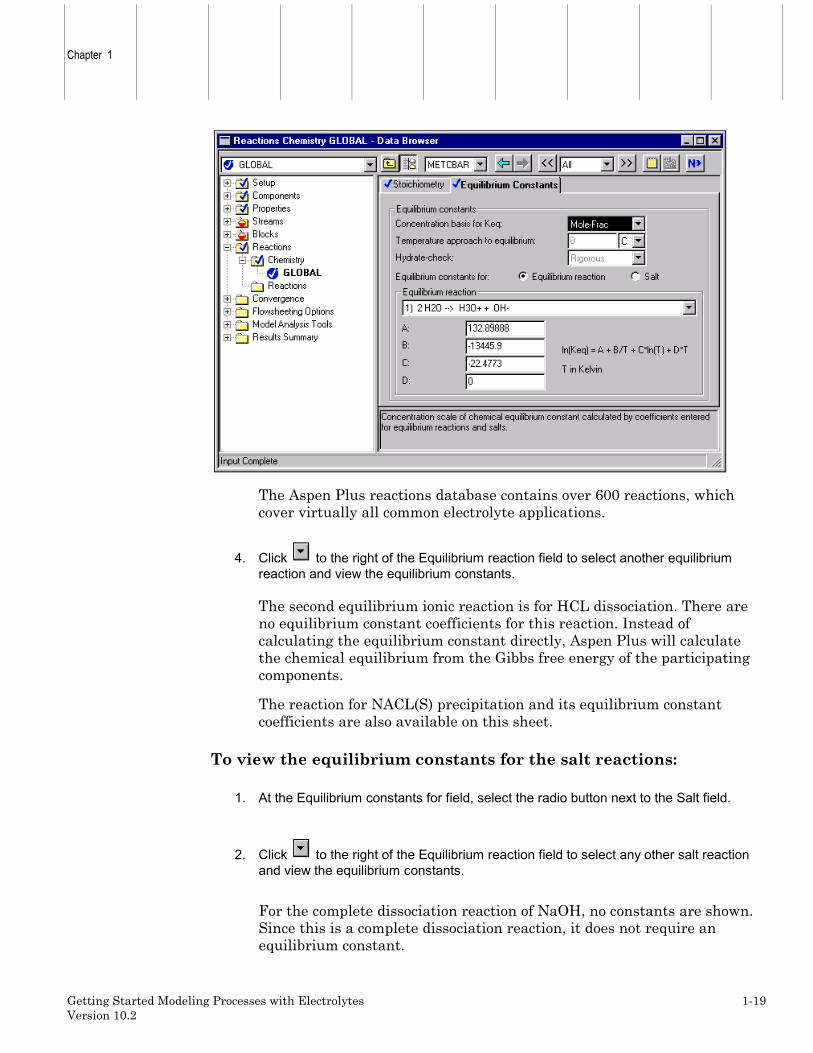
3. Select the Equilibrium Constants sheet.
The optional equilibrium constant coefficients have been automaticallyretrieved from the Aspen Plus reactions database. The equilibriumconstants are located on the Reactions Chemistry EquilibriumConstants sheet.
Chapter 1
Getting Started Modeling Processes with Electrolytes 1-19Version 10.2
The Aspen Plus reactions database contains over 600 reactions, whichcover virtually all common electrolyte applications.
4. Click to the right of the Equilibrium reaction field to select another equilibriumreaction and view the equilibrium constants.
The second equilibrium ionic reaction is for HCL dissociation. There areno equilibrium constant coefficients for this reaction. Instead ofcalculating the equilibrium constant directly, Aspen Plus will calculatethe chemical equilibrium from the Gibbs free energy of the participatingcomponents.
The reaction for NACL(S) precipitation and its equilibrium constantcoefficients are also available on this sheet.
To view the equilibrium constants for the salt reactions:
1. At the Equilibrium constants for field, select the radio button next to the Salt field.
2. Click to the right of the Equilibrium reaction field to select any other salt reactionand view the equilibrium constants.
For the complete dissociation reaction of NaOH, no constants are shown.Since this is a complete dissociation reaction, it does not require anequilibrium constant.

ModelingElectrolyteChemistry
1-20 Getting Started Modeling Processes with ElectrolytesVersion 10.2
Note If you had your own equilibrium constant coefficients, oradditional reactions you would like to include, enter themdirectly on this sheet.

Chapter 1
Getting Started Modeling Processes with Electrolytes 1-21Version 10.2
Selecting Electrolyte Property Models
The Properties Specifications Global sheet is used to enter the thermodynamicmethods used to calculate the properties used in the simulation.
1. From the Data Browser, select the Properties folder and then select Specifications.
The Properties Specifications Global sheet appears. The ElectrolytesWizard has already completed this sheet:
The Electrolyte-NRTL activity coefficient model, ELECNRTL, is therecommended option set for simulations with electrolytes. ELECNRTLcalculates liquid phase properties from the Electrolyte-NRTL activitycoefficient model. Vapor phase properties are calculated from the Redlich-Kwong equation of state.
ELECNRTL can represent aqueous and aqueous/organic electrolytesystems over the entire range of electrolyte concentrations with a singleset of binary interaction parameters. In the absence of electrolytes, themodel reduces to the standard NRTL model.
ModelingElectrolyteChemistry
1-22 Getting Started Modeling Processes with ElectrolytesVersion 10.2
Aspen Plus contains a databank of binary interaction parameters betweenwater and over 600 electrolyte ion pairs. If the binary interactionparameters between any solvent and an electrolyte ion pair are missingfrom the databank, and you do not provide values, Aspen Plus providesreasonable default values.
2. Click to continue.
The Binary Interaction HENRY-1 sheet appears.
Use this sheet to view the Henry's Law parameters retrieved by theelectrolytes expert system. If you had your own Henry's Law parameters,enter them on this sheet.
3. Click to continue.
The Binary Interaction VLCLK-1 sheet appears.
Use this sheet to view the Clarke density parameters retrieved by theelectrolytes expert system. If you had your own Clarke densityparameters, enter them on this sheet.
4. From the Data Browser, select the Electrolyte Pair folder.
The Electrolyte Pair sheets define the electrolyte pair parameters:GMELCC, GMELCD, GMELCE, and GMELCN. If you had your own pairparameters, enter them on these sheets.
5. Click to continue.
The Electrolyte Pair GMELCC-1 Input sheet appears.
6. Click to continue.
The Electrolyte Pair GMELCD-1 Input sheet appears.
7. Click to continue.

Chapter 1
Getting Started Modeling Processes with Electrolytes 1-23Version 10.2
The Electrolyte Pair GMELCE-1 Input sheet appears.
8. Click to continue.
The Electrolyte Pair GMELCN-1 Input sheet appears.
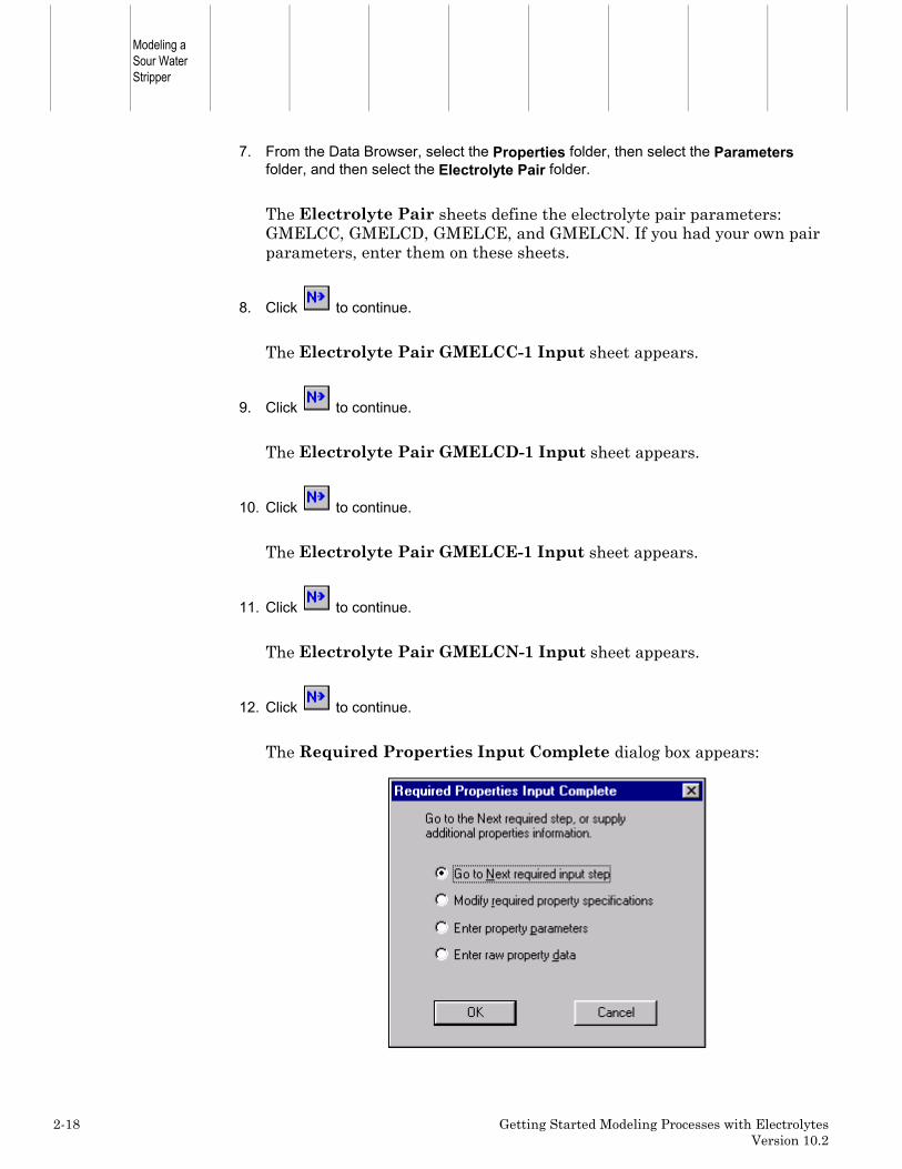
9. Click to continue.
The Required Properties Input Complete dialog box appears:
Correct representation of physical properties is essential to processmodeling. For many simulations, the only physical property specificationthat you must provide is the selection of an option set. This dialog boxshows that the Aspen Plus physical property system has many optionalcapabilities to increase the accuracy of the physical property calculations.
Because the Aspen Plus electrolytes database has data for all componentsand pairs in this simulation, you don't need to provide any optionalspecifications or data.
Now that the Components and Properties specifications are complete,complete the rest of the flowsheet specifications in the same way as fornonelectrolytes. There are no stream or block restrictions in usingAspen Plus electrolytes. Use all Aspen Plus unit operation models in anelectrolytes simulation.
10. Click to move to the next required input.

ModelingElectrolyteChemistry
1-24 Getting Started Modeling Processes with ElectrolytesVersion 10.2
Entering Stream Data
The Streams HCL Input sheet appears. Aspen Plus requires twothermodynamic specifications and enough information to calculate the flow rateof each component.
1. On the Streams HCL Input Specifications sheet, enter the following:
Temperature 25 CPressure 1 BarH2O flow value 10 kmol/hrHCL flow value 1 kmol/hr
You entered the flow specifications for this stream in terms of the basecomponents (the apparent components). Although you are using the truecomponent approach in this simulation, Aspen Plus can accept streamspecifications in terms of the apparent components as well as the truecomponents. Aspen Plus converts the apparent component flowspecifications to true component specifications.
2. Click to continue.
The Streams NAOH Input sheet appears.
3. On the Streams NAOH Input Specifications sheet, enter the following:
Temperature 25 CPressure 1 BarH2O flow value 10 kmol/hrNAOH flow value 1.1 kmol/hr
4. Click to continue.

Chapter 1
Getting Started Modeling Processes with Electrolytes 1-25Version 10.2
Specifying the Flash Block
The FLASH Input Specifications sheet appears. For this simulation, specifythe pressure drop and vapor fraction.
1. In the Temperature field, click , select Vapor fraction, and then enter 0.75.
2. In the Pressure field, enter 0 (indicating there is no pressure drop).
3. Click to continue.
The MIX Input Flash Options sheet appears. As the prompt says, thezero default pressure indicates no pressure drop, which is correct for thissimulation.
4. Click to continue.
The Required Input Complete dialog box appears informing you thatall required input is complete and asking if you want to run thesimulation.
Before running the simulation, request that certain optional properties beincluded in the stream report.
5. Click to close the dialog box without running the simulation.

ModelingElectrolyteChemistry
1-26 Getting Started Modeling Processes with ElectrolytesVersion 10.2
Specifying Additional Stream Properties
By default, the only component properties that Aspen Plus calculates and reportsfor this simulation are component mass flows. Since you are using the truecomponent approach, the component flows will be in terms of the componentsactually present at equilibrium, not the apparent (base) components.
To specify additional properties:
1. From the Data Browser, select the Setup folder and then select Report Options.
On the Setup Report Options sheet, you specify the stream propertiesto be calculated and reported. For this simulation, request that componentmass fractions be calculated and reported.
2. Select the Stream tab.
3. Under Fractions Basis, select the checkbox next to Mass.
You can also define additional stream properties to be calculated andreported, using Aspen Plus Property Sets. Aspen Plus provides a numberof built-in Property Sets based on the Application Type you selected. Youcan also define your own Property Sets. In this simulation, you will use abuilt-in Property Set to report the bubble point of each stream, and asecond built-in Property Set to report the mass fractions of the apparentcomponents in each stream.
4. Click .

Chapter 1
Getting Started Modeling Processes with Electrolytes 1-27Version 10.2
The Property Sets dialog box appears.
5. From the Available Property Sets column, select TBUBBLE and WXAPP.
6. Click to move the selected property sets to the Selected Property Setscolumn.
7. Click .
8. Click to continue.
ModelingElectrolyteChemistry
1-28 Getting Started Modeling Processes with ElectrolytesVersion 10.2
Running the Simulation
The Required Input Complete dialog box appears.
1. Click to run the simulation.
The Control Panel appears.
As the run proceeds, status messages appear in the Control Panel. Ittakes about a minute for Aspen Plus to process input specifications andpersheet the simulation.
Aspen Plus has a special databank it searches only when you use theELECNRTL option set, as in this simulation. Some physical propertyparameters in this databank may be different from the parameters in thestandard non-electrolyte databanks. The values of the physical propertyparameters in the special databank were determined to provide a betterfit for electrolyte systems, and are not generally applicable.
When values are retrieved from this special databank, Aspen Plusgenerates messages in the Control Panel to inform you what propertiesare retrieved for which components.
When the calculations finish, the message Results Available appears inthe status area at the bottom right of the main window.
2. Use the vertical scrollbar to the right of the Control Panel window to see themessages.
3. Examine the results of your run.

Chapter 1
Getting Started Modeling Processes with Electrolytes 1-29Version 10.2
Examining Simulation Results
To view the results of the simulation:
1. From the Control Panel, click .
The Run Status Summary sheet appears, indicating that the simulationcompleted normally.
2. Click to move to the next results sheet.
The Results Summary Streams sheet appears.
3. Review the results on this sheet.
4. Use the horizontal scrollbar on the bottom of the sheet to review results that are off thescreen.
ModelingElectrolyteChemistry
1-30 Getting Started Modeling Processes with ElectrolytesVersion 10.2
Since you selected the True Component approach, results for Mass Flowand Mass Frac are in terms of true components.
Although you specified the flow rates in terms of the apparent components(1 kmol/hr HCL and 10 kmol/hr H2O), Aspen Plus calculated the flowrates of the true components. In stream HCL, there is only a trace ofmolecular HCL remaining. Virtually all of the HCL is dissociated intoH3O+ and CL_. Since the HCL dissociation consumes a mole of water, theoverall H2O flow rate is reduced from 180 kg/hr (10 kmol/hr) to 162 kg/hr(9 kmol/hr).
You also specified the NAOH stream in terms of apparent components(1.1 kmol/hr NAOH and 10 kmol/hr H2O). NAOH dissociates completelyinto NA+ and OH-. This is reflected by the complete disappearance ofmolecular NAOH in this stream.
Stream HCL and Stream NAOH are added together in block MIX to sheetStream MIXED. Because water dissociation is included as one ofelectrolytes reactions, MIX allows H3O+ and OH- to recombine to sheetwater. The heat of this reaction raises the temperature of Stream MIXEDfrom 25 C (the temperature of both inlets) to 61 C. This demonstrates thatthe heat of electrolyte reactions (including the heat of mixing) isautomatically included in Aspen Plus electrolytes calculations.
Stream MIXED feeds a Flash2 block where water is boiled off. Becauseions and precipitated salts are nonvolatile, Stream VAPOR only containspure water. As the ions are concentrated in Stream LIQUID, the solubilitylimit of NACL in water is exceeded, causing 30 kg/hr of molecularNACL(S) to precipitate.
Examine the bubble temperature for stream MIXED and stream LIQUID.Stream MIXED is subsaturated in NACL and stream LIQUID issaturated with NACL. Aspen Plus correctly calculates the bubble point ofLIQUID (110 C) as greater than the bubble point of MIXED (103 C),which is greater than the boiling point of pure water at 1 bar (99.6 C).
Compare the apparent mass fractions for the liquid phase with the truecomponent mass fractions in stream LIQUID. Even though streamLIQUID has precipitated NACL(S), the apparent mass fraction ofNACL(S) is zero because Aspen Plus does not consider precipitated saltsto be apparent components. The apparent mass fractions of the ions NA+,H3O+, OH-, and CL- are also zero. Precipitated salts and ions can only betrue components.
Since the precipitated NACL(S) is not an apparent component, it isrepresented in the apparent component approach in terms of the originalspecies that combined to sheet NACL(S): NAOH, and HCL. This is whythe apparent component basis mass fraction of NAOH is 0.209 eventhough the true component basis mass fraction of NAOH is zero.

Chapter 1
Getting Started Modeling Processes with Electrolytes 1-31Version 10.2
You have now viewed the most relevant results for an electrolytessimulation.
Note This simulation has other Results sheets. Click toview them, if you choose.

ModelingElectrolyteChemistry
1-32 Getting Started Modeling Processes with ElectrolytesVersion 10.2
Exiting Aspen Plus
To exit from Aspen Plus:
1. From the Aspen Plus menu, select File and then select Exit.
The Aspen Plus dialog box appears.
2. Click .
– or –
Click if you want to save the run, and enter a Run ID when prompted.
This simulation (using the apparent approach) is delivered as backup fileelec1 in the Aspen Plus Examples Library. Use this backup file to checkyour results.
❖ ❖ ❖ ❖
Chapter 2
Getting Started Modeling Processes with Electrolytes 2-1Version 10.2
2 Modeling a Sour WaterStripper
In this simulation, use a distillation column to strip NH3 and H2S from a sourwater feed stream.
You will:• Modify the generated Chemistry• Use the apparent component approach for electrolytes• Define a stream property (Property Set)• Convert the simulation from the apparent approach to the true approach
Allow about 45 minutes to do this simulation.
Modeling aSour WaterStripper
2-2 Getting Started Modeling Processes with ElectrolytesVersion 10.2
Sour Water Stripper Flowsheet
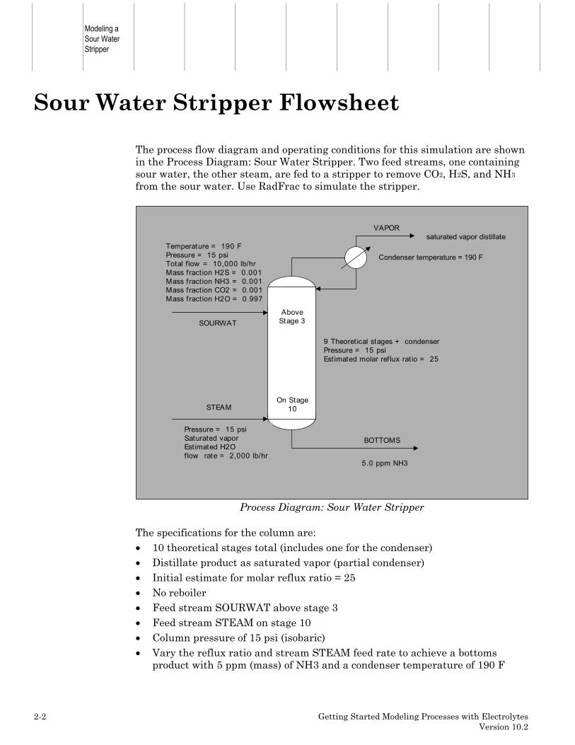
The process flow diagram and operating conditions for this simulation are shownin the Process Diagram: Sour Water Stripper. Two feed streams, one containingsour water, the other steam, are fed to a stripper to remove CO2, H2S, and NH3
from the sour water. Use RadFrac to simulate the stripper.
SOURWAT
STEAM
BOTTOMS
VAPOR
Temperature = 190 FPressure = 15 psiTotal flow = 10,000 lb/hrMass fract ion H2S = 0.001Mass fract ion NH3 = 0.001Mass fract ion CO2 = 0.001Mass fract ion H2O = 0.997
Pressure = 15 psiSaturated vaporEstimated H2O flow rate = 2,000 lb/hr
AboveStage 3
On Stage10
5.0 ppm NH3
9 Theoret ical stages + condenserPressure = 15 psiEst imated molar ref lux rat io = 25
Condenser temperature = 190 F
saturated vapor distillate
Process Diagram: Sour Water Stripper
The specifications for the column are:• 10 theoretical stages total (includes one for the condenser)• Distillate product as saturated vapor (partial condenser)• Initial estimate for molar reflux ratio = 25• No reboiler• Feed stream SOURWAT above stage 3• Feed stream STEAM on stage 10• Column pressure of 15 psi (isobaric)• Vary the reflux ratio and stream STEAM feed rate to achieve a bottoms
product with 5 ppm (mass) of NH3 and a condenser temperature of 190 F

Chapter 2
Getting Started Modeling Processes with Electrolytes 2-3Version 10.2
Starting Aspen Plus
To start Aspen Plus:
1. From your desktop, select Start and then select Programs.
2. Select AspenTech, then Aspen Plus 10.2, then Aspen Plus User Interface.
Note If the Connect to Engine dialog box appears, seeAppendix A.
The Aspen Plus Startup dialog box appears. Aspen Plus displays adialog box whenever you must enter information or make a selectionbefore proceeding. In this simulation, use an Aspen Plus template.
To select the Template option:
1. Select the Template radio button and click .
The New dialog box appears.
Use the New dialog box to specify the application type and the run typefor the new run. Aspen Plus uses the application type you choose toautomatically set various defaults appropriate to your application.
To specify the Application Type and Run Type for the new run:
1. Select the Electrolytes with English Units template.
Note The default Run Type, Flowsheet, is appropriate for thissimulation.
2. Click to apply these options.

Modeling aSour WaterStripper
2-4 Getting Started Modeling Processes with ElectrolytesVersion 10.2
It will take a few seconds for Aspen Plus to apply these options.
Note If the Connect Host dialog box appears, see Appendix A.
The Aspen Plus window is now active.

Chapter 2
Getting Started Modeling Processes with Electrolytes 2-5Version 10.2
Drawing the Graphical SimulationFlowsheet
In this simulation, begin to build the process flowsheet. Since you will enter yourown block and stream IDs, turn off the default Create auto block ID and Createauto stream ID options, which provide these IDs automatically.
1. From the Aspen Plus toolbar, select Tools and then select Options.
The Options dialog box appears.
2. Select the Flowsheet tab.
3. Deselect the Automatically Assign Block Name with Prefix and the AutomaticallyAssign Stream Name with Prefix options.
4. Click to close the Options dialog box and apply the changes.
Modeling aSour WaterStripper
2-6 Getting Started Modeling Processes with ElectrolytesVersion 10.2
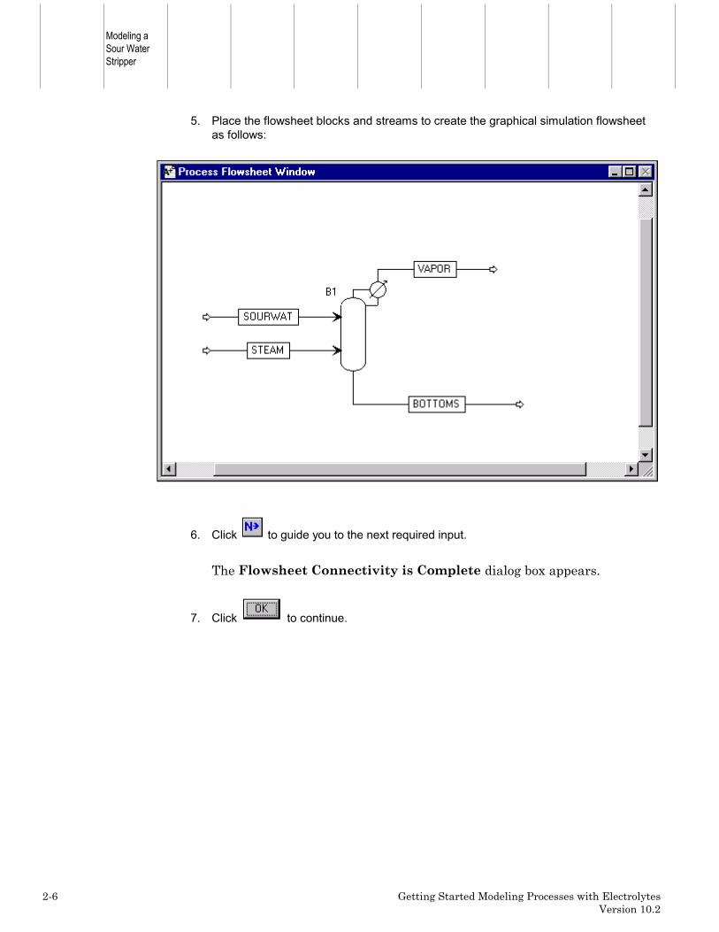
5. Place the flowsheet blocks and streams to create the graphical simulation flowsheetas follows:
6. Click to guide you to the next required input.
The Flowsheet Connectivity is Complete dialog box appears.
7. Click to continue.

Chapter 2
Getting Started Modeling Processes with Electrolytes 2-7Version 10.2
Specifying Title, Stream Properties, andGlobal Options
The Data Browser window appears. The Setup Specifications Global sheetdisplays defaults Aspen Plus uses for other sheets.
Use this sheet to give your simulation a title, and to review the stream propertiesand global options that were set when you selected the Electrolytes with EnglishUnits application type.
Note The Run type field displays Flowsheet, which is appropriate forthis simulation.
The Electrolytes with English Units application type sets the following globaldefaults for electrolytes applications:• ENG units (English units)• Mass Flow basis for all flow inputs
It is always good practice to enter a title for the simulation.
1. In the Title field, enter Getting Started with Electrolytes - Simulation 2.

Modeling aSour WaterStripper
2-8 Getting Started Modeling Processes with ElectrolytesVersion 10.2
Based on the Electrolytes with Metric Units template, Aspen Plusdisplays the following defaults for calculating and reporting streamproperties:• Flow and Fraction Basis of Mass: Aspen Plus will report the
component flow rates on a mass flow basis.• ELEC_E Stream Sheetat: Aspen Plus sheetats the Stream Summary
sheet for electrolytes.
To review the report options specified in the selected Template:
1. From the Data Browser, select the Setup Report Options sheet.
2. Select the Stream sheet.
To move to the next required input sheet:
1. From the Data Browser, select the Components folder and then select Specifications.

Chapter 2
Getting Started Modeling Processes with Electrolytes 2-9Version 10.2
Specifying Components
The Components Specifications Selection sheet appears.
The apparent (or base) components for this simulation are H2O, NH3, H2S, andCO2. Because you chose an electrolytes Application Type, water already appearson the sheet.
Note Because the sheetula for ammonia is represented as H3N in theAspen Plus databank, you must identify NH3 by entering eitherthe component name (ammonia) or the sheetula (H3N).
1. Enter the following components:
H2O WaterNH3 AmmoniaH2S Hydrogen-SulfideCO2 Carbon-Dioxide
2. Click .
The Electrolytes Wizard dialog box, for defining automatic chemistrygeneration, appears.

Modeling aSour WaterStripper
2-10 Getting Started Modeling Processes with ElectrolytesVersion 10.2
The Electrolytes Wizard
Use the Electrolytes Wizard dialog box to define the ionic species that can begenerated from the base components you specified on the ComponentsSpecifications sheet, and to generate the reactions that occur among thesecomponents in the liquid phase.
1. On the Electrolytes Wizard dialog box, click .
2. Click to move all components in the Available components column to theSelected components column.
3. Click to continue.
The Generated Species and Reaction dialog box appears:

Chapter 2
Getting Started Modeling Processes with Electrolytes 2-11Version 10.2
Aspen Plus generates all possible ionic species and reactions for the H2O-NH3-H2S-CO2 system.
In the Generated Reactions list, different-style arrows denote thefollowing reaction types:
<<===>> Denotes ionic equilibrium and salt precipitation
--->> Denotes complete dissociation
For this simulation, you know that ammonium carbamate sheetation canbe neglected.
To remove ammonium carbamate sheetation from the solutionchemistry:
1. Select NH2COO- aqueous species.
2. Click .
Now that you have removed NH2COO- from the Generated AqueousSpecies list, Aspen Plus automatically removes all reactions involvingNH2COO- from the Reactions list.
The salts are also not relevant.
To remove the salts from the solution chemistry:
1. Select NH4HS(S) and NH4HCO3(S) from the Salts list.
2. Click .

Modeling aSour WaterStripper
2-12 Getting Started Modeling Processes with ElectrolytesVersion 10.2
Note Any time you know that a reaction can be neglected because ofexpected process conditions, remove it from the solutionchemistry, to decrease the execution time required for yoursimulation.
In this example, only ionic equilibrium reactions are generated. Theremaining six generated reactions represent partial dissociation of water,partial dissociation of H2S to HS- and S-2, partial dissociation of CO2 toHCO3- and CO3-2, and partial dissociation of NH3 to NH4+.
3. On the Generated Species and Reactions dialog box click to acceptthe generated species and reactions.
The Simulation Approach dialog box appears, allowing you to choosebetween the true species approach and the apparent component approach.For this simulation, use the apparent component approach.
Chapter 2
Getting Started Modeling Processes with Electrolytes 2-13Version 10.2
When you use the apparent component approach, Aspen Plus solves theequations describing solution chemistry as part of the physical propertycalculations. Aspen Plus modifies the physical properties of the apparentcomponents to account for the reactions described by the solutionchemistry. The ions and precipitated salts are not seen by the unitoperation models.
The apparent component approach also defines how Aspen Plus reportssimulation results. The component flow rates for ions are not reported.Instead, Aspen Plus reports the component flow rates of the apparentcomponents as if no dissociation occurred.
For example, the generated Chemistry for this system specifies that H2Spartially dissociates into HS- and S-2. If you choose the apparentcomponent approach, Aspen Plus will report a value for the mole flow rateof H2S that includes molecular H2S, HS-, and S-2.
4. Select the radio button next to Apparent component approach.
5. Click to move to the next dialog box.
The Summary dialog box appears, providing Aspen Plus electrolytesexpert system information.
6. Click to close the dialog box.
On the Components Specifications sheet, Aspen Plus has now addedthe generated electrolyte components. Since all components are databankcomponents, Aspen Plus automatically retrieves all relevant physicalproperty parameters.

Modeling aSour WaterStripper
2-14 Getting Started Modeling Processes with ElectrolytesVersion 10.2
7. Click to continue.
The Components Henry Comps Global sheet appears for the HenryComps group GLOBAL, which was defined by the electrolytes expertsystem. Use this sheet to see which components have been declared asHenry's Law components by the electrolytes expert system. If you hadadditional Henry's Law components in your simulation (such as nitrogenand oxygen), you could add them to the list on this sheet.

Chapter 2
Getting Started Modeling Processes with Electrolytes 2-15Version 10.2
Examining Generated Chemistry
In the previous step, the Aspen Plus Electrolytes Wizard automatically generatedthe chemistry definition for your simulation and named it GLOBAL.
To examine the generated Chemistry:
1. From the Data Browser, select the Reactions folder.
2. From the Reactions folder, select the Chemistry folder and then select Global.
The Reactions Chemistry Global sheet appears.
To view the generated chemistry:
1. Select a Reaction and click .
The Equilibrium Reaction Stoichiometry dialog box appears, with thedata for the selected reaction that was generated by the ElectrolytesWizard.
2. Close the dialog box and view the other reactions using the same steps.
Note All six reactions have equilibrium constant that have beenretrieved from the Aspen Plus reactions database.

Modeling aSour WaterStripper
2-16 Getting Started Modeling Processes with ElectrolytesVersion 10.2
3. From the Data Browser, select the Properties folder and then select Specifications.

Chapter 2
Getting Started Modeling Processes with Electrolytes 2-17Version 10.2
The Properties Specifications sheet appears. The Electrolytes Wizardhas already completed this sheet:
4. Select the checkbox next to Use True-Components.
5. Click to continue.
The Binary Interaction sheet appears for the binary parametersHENRY-1. Use this sheet to view the Henry's Law parameters retrievedby the electrolytes expert system. If you had your own Henry's Lawparameters, enter them on this sheet.
6. Click to continue.
The Binary Interaction sheet appears for the binary parameters NRTL-1. Use this sheet to view the molecule-molecule interaction parametersretrieved by the electrolytes expert system. If you had your own molecule-molecule interaction parameters, enter them on this sheet.
Modeling aSour WaterStripper
2-18 Getting Started Modeling Processes with ElectrolytesVersion 10.2
7. From the Data Browser, select the Properties folder, then select the Parametersfolder, and then select the Electrolyte Pair folder.
The Electrolyte Pair sheets define the electrolyte pair parameters:GMELCC, GMELCD, GMELCE, and GMELCN. If you had your own pairparameters, enter them on these sheets.
8. Click to continue.
The Electrolyte Pair GMELCC-1 Input sheet appears.
9. Click to continue.
The Electrolyte Pair GMELCD-1 Input sheet appears.
10. Click to continue.
The Electrolyte Pair GMELCE-1 Input sheet appears.
11. Click to continue.
The Electrolyte Pair GMELCN-1 Input sheet appears.
12. Click to continue.
The Required Properties Input Complete dialog box appears:

Chapter 2
Getting Started Modeling Processes with Electrolytes 2-19Version 10.2
Correct representation of physical properties is essential to processmodeling. For many simulations, the only physical property specificationthat you must provide is the selection of an option set. This dialog boxshows that the Aspen Plus physical property system has many optionalcapabilities to increase the accuracy of the physical property calculations.
Because the Aspen Plus electrolytes database has data for all componentsand pairs in this system, you don't need to provide any optionalspecifications or data.
Now that the Components and Properties specifications are complete,complete the rest of the flowsheet specifications in the same way as fornonelectrolytes. Use all Aspen Plus unit operation models in anelectrolytes simulation.
13. Click to move to the next required input.

Modeling aSour WaterStripper
2-20 Getting Started Modeling Processes with ElectrolytesVersion 10.2
Entering Stream Data
The Streams SOURWAT Input sheet appears. Aspen Plus requires twothermodynamic specifications and enough information to calculate the molar flowrate of each component.
1. On the Streams SOURWAT Input Specifications sheet, enter the following:
Temperature 190 F
Pressure 15 PSI
Total flow Mass 10000 LB/HR
2. In the Composition field, click and select Mass-Frac.
3. Enter the following mass fraction values:
H2O 0.997
NH3 0.001
H2S 0.001
CO2 0.001

Chapter 2
Getting Started Modeling Processes with Electrolytes 2-21Version 10.2
4. Click to continue.
The Streams STEAM Input sheet appears.
5. On the Streams Steam Input Specifications sheet, enter the following:
Pressure 15 PSIVapor Fraction 1Composition Mass-FlowH2O Mass flow value 2000 LB/HR
6. Click to continue.

Modeling aSour WaterStripper
2-22 Getting Started Modeling Processes with ElectrolytesVersion 10.2
Specifying the RadFrac Block
The Block B1 Setup sheet appears.
To review the types of specifications that you can make for aRadFrac block:
1. Use Help on the RadFrac Setup sheet.
2. Review the types of specifications, then when you are ready to continue, close theHelp window.
3. On the Block B1 Setup Configuration sheet, enter the following:
Number of stages 10 (9 theoretical stages and condenser)
Condenser Partial-Vapor
Reboiler None
4. In the Operating Specifications section, at the Reflux Ratio field, select Mole andspecify 25 as the initial estimate for reflux ratio.

Chapter 2
Getting Started Modeling Processes with Electrolytes 2-23Version 10.2
The Block B1 Setup Configuration sheet is complete:
5. Click to continue.
The Block B1 Setup Streams sheet appears. Use this sheet to describehow the streams are connected to the RadFrac block.
6. For the SOURWAT feed stream, enter 3 in the Stage field and Above-Stage in theConvention field.
7. For the STEAM feed stream, enter 10 in the Stage field and On-Stage in theConvention field.
Because stream VAPOR is connected to the vapor distillate port,Aspen Plus automatically assigns stream VAPOR as a vapor phaseproduct from stage 1. Similarly, Aspen Plus assigns stream BOTTOMS asa liquid phase product from stage 10. The Blocks B1 Setup Streams sheetdoes not accept flow specifications for distillate product or bottomsproduct streams.
8. Click to continue.
The Setup Pressure sheet appears.

Modeling aSour WaterStripper
2-24 Getting Started Modeling Processes with ElectrolytesVersion 10.2
To specify that this column operates isobarically at 15 psia:
1. In the Stage 1 / Condenser pressure field, enter 15 PSI.
2. Click to continue.
The Required Input Complete dialog box appears, indicating that allrequired input specifications for RadFrac Block B1 have been entered:
3. Click to close the dialog box.
You can now enter optional specifications. These specifications includesetting up two design specifications. The first will be a concentration of 50ppm NH3 in BOTTOMS, and the second will be a condenser temperatureof 190°F.
To define the first design specification:
1. From the Data Browser, click the Blocks B1 Design Specs folder.
The Design Specs Object Manager appears.
2. Click .

Chapter 2
Getting Started Modeling Processes with Electrolytes 2-25Version 10.2
The Create new ID dialog box appears:
3. In the Create new ID dialog box , click to accept 1 (the default ID).
The Design Specs 1 sheet appears.
4. In the Type field, click and select Mass purity.
5. In the Target field, enter the value 5.0E-5.
Note Specify where this specification is to be applied, and whatcomponent and phase it applies to.
6. Click to continue.
The Design Specs 1 Components sheet appears.
7. From the Available components column, select NH3 (AMMONIA) and click .
8. Click to continue.
The Design Specs 1 Feed/Product Streams sheet appears.
9. From the Available streams column, select BOTTOMS and click .

Modeling aSour WaterStripper
2-26 Getting Started Modeling Processes with ElectrolytesVersion 10.2
The Design Specs 1 sheet is complete:
To define another design specification:
1. From the Data Browser, select the Design Specs folder.
The Design Specs Object Manager appears.
2. Click .
3. In the Create new ID dialog box , click to accept 2 (the default ID).
A new Design Specs Specifications sheet appears.
4. In the Type field, enter Stage temperature.
5. In the Target field, enter 190 F.
6. In the Stage field, enter 1.

Chapter 2
Getting Started Modeling Processes with Electrolytes 2-27Version 10.2
7. Click to continue.
The Vary Object Manager appears.
Define two manipulated variables to meet the two design specifications. Inthis simulation keep free the steam feed rate and the reflux ratiospecifications provided on the Blocks B1 Setup sheet. Aspen Plus adjuststhe steam feed rate and reflux ratio to achieve the NH3 bottomsconcentration specification and the condenser temperature specification.
To define the first manipulated variable:
1. Click and then click .
The Vary 1 Specifications sheet appears.
On this sheet, specify which input variables you want to keep free in orderto meet the design specifications you provide.
2. In the Type field, enter Feed rate.
3. In the Stream name field, enter STEAM.
4. In the Lower bound field, enter 50 lbmol/hr.
5. In the Upper bound field, enter 200 lbmol/hr.
On the Streams STEAM sheet you specified a Mass-Flow for StreamSTEAM. However, when you select the variable type Feed rate on theVary 1 sheet, Aspen Plus assumes the Feed rate to be on a mole basis. Inthis case, varying the Feed rate on a mole basis from 50-200 (lbmol/hr) isequivalent to varying the Mass flow from 900-3600 (lb/hr).

Modeling aSour WaterStripper
2-28 Getting Started Modeling Processes with ElectrolytesVersion 10.2
To define the second manipulated variable:
1. From the Data Browser, select the Vary folder.
2. Click and then click .
3. In the Type field, enter Reflux ratio.
4. In the Lower bound field, enter 15.
5. In the Upper bound field, enter 50.
As with Feed rate, Aspen Plus always varies the reflux ratio on a molebasis, even if you specify a Mass Reflux ratio on the Blocks B1 sheet.
6. Click to continue.
The Required Input Complete dialog box appears, indicating that allrequired specifications are complete.
Chapter 2
Getting Started Modeling Processes with Electrolytes 2-29Version 10.2
7. Click .
By default, Aspen Plus displays results only for stages that have feeds,products, heaters, or a maximum or minimum flow, and for the stagesimmediately above and below those stages. Modify the default stagereport so that results are reported for all stages.
To change the report:
1. From the Data Browser, select the Blocks folder, then select the B1 folder, and thenselect Report.
The Report Properties Options sheet appears.
2. Select the Report Profile Options sheet.
3. On the Report Profile Options sheet, select the radio button next to the All Stagesfield.
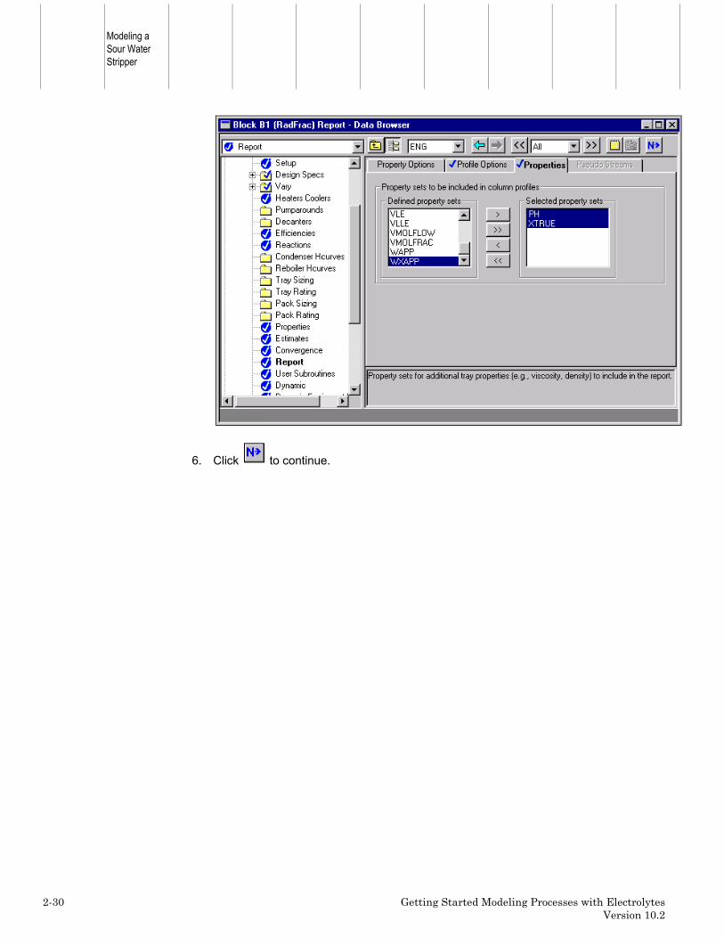
By default, Aspen Plus reports only temperature, pressure, total moleflows, enthalpy, mole fractions and K-values for the selected trays.Request that additional properties be reported by selecting additionalproperty sets on the Property Options sheet.
Specify that Aspen Plus report pH and true component mole fractions,using two built-in Property Sets.
4. Select the Report Properties sheet.
5. In the Defined property sets column, select PH and XTRUE and click to movethe selected property sets into the Selected property sets column.
Modeling aSour WaterStripper
2-30 Getting Started Modeling Processes with ElectrolytesVersion 10.2
6. Click to continue.

Chapter 2
Getting Started Modeling Processes with Electrolytes 2-31Version 10.2
Running the Simulation
The Required Input Complete dialog box appears.
1. Click to run the simulation.
The Control Panel appears.
As the run proceeds, messages appear in the Control Panel. It takes a fewminutes for Aspen Plus to process input specifications and persheet thesimulation.
As in simulation 1, Aspen Plus displays messages indicating that someproperties have been retrieved from a special databank.
When the calculations finish, the message Results Available appears inthe status area at the right of the main window toolbar.
2. When the message Results Available appears in the toolbar, click to view theresults of your run.

Modeling aSour WaterStripper
2-32 Getting Started Modeling Processes with ElectrolytesVersion 10.2
Examining Simulation Results
Aspen Plus generates many results for this simulation. Examine any results thatare of interest to you. This simulation guides you through a review of some of thesimulation results.
To view RadFrac results:
1. Select the Process Flowsheet tab at the bottom of the screen.
2. On the graphical simulation flowsheet, select the RadFrac block.
3. Right-click on the mouse and select Results.
The Blocks B1 Results Summary sheet appears. This sheet reports theflows, temperatures, and duties for the top and bottom stage of thecolumn.
4. Click to move to the next results sheet.
The Balance sheet appears. The block is in mass balance, but is not inenthalpy balance, because heat is being removed from the RadFrac blockin the condenser. The enthalpy would have balanced if you had assigned aheat stream to the condenser duty.

Chapter 2
Getting Started Modeling Processes with Electrolytes 2-33Version 10.2
A summary of the results of the design specifications is located on theDesign Specs Results sheet. This sheet reports the specified values andthe final values for all of the design specifications.
To view these results:
1. From the Data Browser, select the Design Specs folder.
2. Select the Results sheet to view the Design Specs results.
A summary of the results of the manipulated variables is located on theVary Results sheet. This sheet reports the specified bounds and the finalvalues for all of the manipulated variables.
To view these results:
1. From the Data Browser, select the Vary folder.
2. Select the Results sheet to view the Vary results.

Modeling aSour WaterStripper
2-34 Getting Started Modeling Processes with ElectrolytesVersion 10.2
The Profiles Compositions sheet lists the mole fractions of eachcomponent for every stage. Since you chose the apparent componentapproach for this simulation, only the apparent components are reported.
To view these results:
1. From the Data Browser, select the Profiles folder.
2. Select the Compositions sheet to view the results.
3. In the View field, click and select Liquid.

Chapter 2
Getting Started Modeling Processes with Electrolytes 2-35Version 10.2
The Profiles Properties sheet reports the actual composition ofmolecular components and ions.
To view these results:
1. Select the Properties sheet.

Modeling aSour WaterStripper
2-36 Getting Started Modeling Processes with ElectrolytesVersion 10.2
Consider the results for Stage 1. The true composition of NH3 andNH4+ sum to 0.03147 on Stage 1. This value is slightly differentfrom the apparent mole fraction of NH3 reported on theCompositions sheet: 0.03138. This slight difference is caused by thesolution chemistry.
In general, the total number of moles is not conserved by solutionchemistry. In this simulation, the fourth equilibrium reactionconsumes 3 moles of reactants and generates two moles ofproducts:
CO2 + 2H2O <<===>>H3O+ + HCO3-
The total number moles on an apparent component basis will bedifferent from the total number of moles on a true componentbasis. Thus XNH3 (apparent basis) is not exactly equal to XNH3 (truebasis) + XNH4+ (true basis).
The liquid composition of apparent NH3 on stage 1 is:
XNH3 = 0.0314
2. Select the Compositions sheet.
3. In the View field, select Vapor.
The vapor composition of apparent NH3 on stage is:
YNH3 = 0.2112
From these two values, you can calculate a K-value for NH3 on stage 1:
K = YNH3/XNH3 = 6.73
4. Select the K-Values sheet.

Chapter 2
Getting Started Modeling Processes with Electrolytes 2-37Version 10.2
The K-value for NH3 on stage 1 is 6.73. These results demonstrate thatwhen you use apparent components, Aspen Plus also reports the K-valuescalculated by RadFrac (or any flash) on an apparent basis.
5. Close all open windows.
Modeling aSour WaterStripper
2-38 Getting Started Modeling Processes with ElectrolytesVersion 10.2
Converting to True Components
Choosing between the true component approach and the apparent component is amatter of personal preference. For all simulations, the simulation results shouldbe equivalent. To demonstrate this, you will convert this simulation from theapparent component approach to the true component approach.
To convert the simulation to the true component approach, you must tellAspen Plus to use the true component approach, and you must adapt the DesignSpec in the RadFrac block (5 ppm mass apparent NH3 in the bottoms).
To tell Aspen Plus to use the true component approach:
1. From the Aspen Plus menu, select Data and then select Properties.
2. On the Properties Specifications Global sheet, select the checkbox next to True-Components.
For the RadFrac block, you entered a desired specification of 5.0 ppm(mass) of apparent NH3 in the bottoms. However, this specification isincorrect for the true component approach, because a significant portion ofthe apparent NH3 is present as NH4+.
To revise the RadFrac design specification to apply to theapparent composition of NH3:
1. On the graphical simulation flowsheet, select the RadFrac block.
2. Right-click inside the RadFrac block and select Input.
3. From the Data Browser, select the Design Specs folder.
The Design Spec Object Manager appears.
4. Select Design Spec ID 1, and click .
The Design Spec Specifications sheet appears. Modify Design Spec 1 tospecify a stream property for the apparent mass fraction of NH3.
5. In the Type field, click and select Property value.

Chapter 2
Getting Started Modeling Processes with Electrolytes 2-39Version 10.2
6. In the Target field, enter 5.0E-6.
7. In the Property set field, right-click the mouse and select New.
8. In the Aspen Plus dialog box, enter XNH3APP as the new property set.
9. Click .
10. Select the Feed/Product Streams sheet.
11. In the Available streams column, select Bottoms and click to move the streamto the Selected stream column.
12. Click to continue.
The Properties Prop-Sets XNH3APP sheet appears.
Aspen Plus uses this property set to calculate the apparent mass fractionof NH3 in the liquid phase.

Modeling aSour WaterStripper
2-40 Getting Started Modeling Processes with ElectrolytesVersion 10.2
13. Click .
14. In the Search Physical Properties dialog box, enter apparent component massfraction in the first field.
15. Click .
The system searches for valid physical properties and displays them inthe second field of the Search Physical Properties dialog box.
16. Select Apparent component mass fraction (alias WXAPP) from the search results.
17. Click .
The system adds the selected physical property and displays it in thethird field of the Search Physical Properties dialog box.
18. Click .
19. Select the Qualifiers sheet.
20. In the Phase field, click and select Liquid.
21. In the Component field, click and select NH3.
22. Click to continue.
The Required Properties Input Complete dialog box appears.
23. Click .

Chapter 2
Getting Started Modeling Processes with Electrolytes 2-41Version 10.2
Running the True Component Simulation
The Required Input Complete dialog box appears insheeting you that allspecifications are complete and the simulation can be run.
1. Click .
When the calculations finish, the message Results Available appears inthe status area at the right of the Main Window toolbar.
2. Close all open windows, and the Control Panel.
To view selected results of the true component simulation:
1. On the graphical simulation flowsheet, select the RadFrac block.
2. Right-click inside the RadFrac block and select Results.
3. From the Data Browser, select the Profiles folder.
4. Select the Compositions sheet to view the results.
5. In the View field, click and select Liquid.
This sheet reports the liquid phase mole fraction for all components,including the ions. Stage 1 reports the following compositions:
X NH3 = 0.02093
X NH4+ = 0.01054
6. In the View field, click and select Vapor.
Note that all ions have a mole fraction of zero in the vapor phase. Stage 1reports the following composition:
Y NH3 = 0.21115
From these values, a stage 1 K-value for NH3 can be calculated.

Modeling aSour WaterStripper
2-42 Getting Started Modeling Processes with ElectrolytesVersion 10.2
K = YNH3/XNH3 = 10.09
7. Select the K-Values sheet.
On stage 1, the reported K value for NH3 matches the value you justcalculated. This demonstrates that when true components are used, theK-values calculated by RadFrac (or any flash) are also reported on a truebasis.
Note that the K-value calculated in the apparent simulation is not equalto the K-value calculated in the true simulation due to the partialdissociation of ammonia.
The table below compares a number of the values calculated in the truecomponent simulation and the apparent component simulation.
Apparent True
Condenser duty (BTU/HR) -1.46E6 -1.46E6
Condenser Temperature (F) 190 190
Bottom Stage Temperature (F) 213 213
Steam Feed Rate (lb/hr) 1787 1787
Molar Reflux Ratio 29.5 29.4
All values are virtually identical. This demonstrates that the resultscalculated by the true approach and the apparent approach areequivalent, even if they are not numerically equal.

Chapter 2
Getting Started Modeling Processes with Electrolytes 2-43Version 10.2
Exiting Aspen Plus
To exit from Aspen Plus:
1. From the Aspen Plus menu, select File and then select Exit.
The Aspen Plus dialog box appears.
2. Click .
– or –
Click if you want to save the run, and enter a Run ID when prompted.
This simulation (using the apparent approach) is delivered as backup fileelec2 in the Aspen Plus Examples Library. Use this backup file to checkyour results.

Modeling aSour WaterStripper
2-44 Getting Started Modeling Processes with ElectrolytesVersion 10.2
❖ ❖ ❖ ❖

Appendix A
Getting Started Modeling Processes with Electrolytes A-1Version 10.2
A Connecting to theAspen Plus SimulationEngine
If either of the following conditions exist, you will be prompted to specify the hostcomputer for the Aspen Plus simulation engine after you start the Aspen PlusUser Interface:• The simulation engine is not installed on your PC.• The simulation engine is installed on your PC, but the Activator security
device is not connected to your PC.
In these cases, the Connect to Engine dialog box appears.
1. In the Server type field, click and select the type of host computer for thesimulation engine.
If you choose Local PC as the server for the simulation engine, you do notneed to enter any more information into the dialog box.
2. Click to continue.
If you choose UNIX host, OpenVMS host, or Windows NT server as theserver for the simulation engine:
3. In the Node name field, enter the node name of the computer on which the AspenPlus simulation engine will execute.

Connecting tothe Aspen PlusSimulationEngine
A-2 Getting Started Modeling Processes with ElectrolytesVersion 10.2
4. In the other fields, enter the following information:
User name Your user name for the specifiedhost/server.
Password Your password for the above username.
Working directory The associated working directory.
5. Click .
When the network connection is established, the message ConnectionEstablished appears in the message box.
If the Connection Established message does not appear, see your Aspen Plussystem administrator for more information on network protocols and hostcomputers for the Aspen Plus simulation engine.
❖ ❖ ❖ ❖