asme imece2010 submitted final 2010-6-11
TRANSCRIPT

8/6/2019 ASME IMECE2010 Submitted Final 2010-6-11
http://slidepdf.com/reader/full/asme-imece2010-submitted-final-2010-6-11 1/6
1 Copyright © 2010 by ASME
“DRAFT” Proceedings of the ASME 2010 International Mechanical Engineering Congress & ExpositionIMECE2010
November 12-18, 2010, Vancouver, British Columbia, Canada
IMECE2010-39118
MINIATURE STEREO IMAGING CONVERTER WITH TRANSLATING APERTURE
Wook ChoiMechanical and Aerospace Engineering Dept.University of California, Los Angeles (UCLA)
Los Angeles, CA, [email protected]
Vladimir RubtsovIntelligent Optical systems, Inc. (IOS)
Torrence, CA, [email protected]
Chang-Jin “CJ” KimMechanical and Aerospace Engineering Dept.University of California, Los Angeles (UCLA)
Los Angeles, CA, [email protected]
ABSTRACT
Depth information from an image can greatly increase the work
efficiency when observing or inspecting objects, because the
size, distance, and relative locations can be estimated. Various
stereo imaging methods are being used to find depth
information in a wide range of application fields, typically by
placing multiple optical systems side-by-side to create multiple
shifted images. In this study, we develop a miniature stereo
image generating device, which can augment an existing single
optical system (i.e., a two-dimensional images capturer) with
three-dimensional capability. Developed with MEMS
technology, the device consists of a single translating aperture,
which shifts laterally between two positions (up to 100 µm
apart demonstrated) by means of electrostatic comb actuators.
Attached at the objective end of conventional (i.e., nonstereo)
optical systems, this stereo converter with an aperture 900 µm
in diameter is shown to successfully generate slightly different
viewing angles, providing stereo images. Being miniaturized,
this device is suitable for microscopic or endoscopic
applications, where the size of the system is limited or axial
depth of focus is relatively large.
1. INTRODUCTION
Analyzing two-dimensional (2D) images to extract three-
dimensional (3D) information is a complex and time-
consuming task mostly relying on limited information such as
shading or surface discontinuity [1-2]. The difficulties in
finding the 3D information, however, can be greatly reduced if
any depth information about an object is provided for the image
analysis. To find such depth information, various stereo
imaging methods are used these days, clarifying the size
distance, and 3D shapes of objects in a range of application
fields. The most common method is using two or more separate
imaging systems having certain distances between them [3-5]
to provide multiple viewing angles using triangulation
methods. However, such multiple imaging systems lead to an
increase in size and structural complexity of the overall system
To address this issue, several stereo systems with a single
imaging system [6-8] or an off-axis aperture [9-11] have been
introduced.
We have previously proposed dramatic miniaturization of
those stereo systems through use of micro electro-mechanica
systems (MEMS) technologies, reporting success with a single
glass disc that flips around the neutral angle in the light path
[12]. The operating mechanism for the flipping was
electrostatic actuation at resonance, consuming low power. The
glass parts, including the glass disc, were fabricated by therma
molding into a micromachined silicon mold, followed by
lapping and polishing steps. Although the device was
successful, we have since been exploring new designs suitable
for more conventional MEMS fabrication, which would be
more reliable and low-cost.
In this study, we report an all-silicon (i.e., no glass parts)
device much simpler in structure and fabrication processes. The
completed device is attachable to an existing optical system

8/6/2019 ASME IMECE2010 Submitted Final 2010-6-11
http://slidepdf.com/reader/full/asme-imece2010-submitted-final-2010-6-11 2/6
2 Copyright © 2010 by ASME
(e.g., a camera or a microscope) to add stereo imaging
capability if a correctly sized aperture is used.
2. IMAGING PRINCIPLE
Several off-axis aperture stereo imaging methods have
been developed as alternatives to multiple-lens stereo imagingmethods to avoid the large size and complexity of the usual
multiple-lens systems. Such off-axis aperture methods include
the use of pinholes (i.e., no lens) located at a certain distance
from the sensor which is widely used in the pinhole stereo
photography, and the use of multiple apertures off-axis in front
of an imaging system with lenses [10]. However, the pinhole
method generally requires a significant exposure time or strong
illumination, which is not suitable for general imaging
applications, while the multiple-apertures method requires
several imaging filters and post imaging processes to extract
separate images coming from each aperture. To avoid those
limitations and complications, a stereo imaging method with a
single translatable aperture placed in front of an existingimaging system [11] is used in this study.
Fig. 1 shows three objects – a square, a triangle, and a
circle – in front of the objective lens of the imaging system,
with the triangle at the focusing distance of the lens. Because of
their different physical distances from the lens, their imaging
locations behind the lens (L1, L2, and L3, respectively) are also
different. If all those three objects are lined up along the optical
axis, it is hard to distinguish their relative locations (Fig. 1(a))
simply by observing the images on the sensor. However, when
a screen with an aperture is placed in front of the lens and
translates up and down, the images of the square and the circle
shift down and up, respectively, while the image of the triangle
remains still. That is, objects closer or farther than the lens
focusing distance have their images on the sensor shifted in thesame or the opposite direction, respectively, as the aperture
translation, providing views from different angles as shown in
Fig. 1 (b) and (c).
If a thin lens is assumed as in Fig. 1 and the aperture is very
close to the lens, the image shift at the sensor can be estimated
by the following equation [9];
D D F v
h
d
1111+⎟
⎠
⎞⎜⎝
⎛ −=
where
Fig. 2 shows the actual image shift test using a translating
aperture. There are two pens placed at different distances; the
ballpoint pen (without a cap) in the front is closer to the camera
than the marker pen (with a cap) in the back. A screen with an
aperture 1 mm in diameter is placed in front of the camera. The
camera is kept focused on the marker pen in the back during
this test. As the aperture is moved up and down, only the image
of the pen in the front which is not in focus shifts while the
image of the pen in the back on which the camera focuses doesnot move, providing depth information to the observer tha
cannot be easily obtained using a regular 2D camera. This
experiment confirms that when an aperture of adequate size is
used in front of the imaging system, only the image of objects
not in focus shifts as the aperture translates, which can be used
to find the relative locations of each object.
(a)
(b)
(c)
Figure 1. Image shift by aperture translation. (a) Objects at
different locations have different imaging distances behind
the lens. When an aperture is used and translates upward (b)
or downward (c), each object has its image on the sensor
shifted according to its relative location.
Figure 2. Captured image shift by a camera. A screen with
an aperture 1 mm in diameter is placed in front of the
camera. The camera focuses on the capped marker pen in
the back. As the aperture translates up and down, only the
image of the opened ballpoint pen in the front shifts while
the image of the pen in the back remains still.
d : distance to an object in front of the lens
v: aperture translating distanceh: image shift at the image sensor
D: distance to a plane conjugate to sensor plane
F : focal length of the lens
8/6/2019 ASME IMECE2010 Submitted Final 2010-6-11
http://slidepdf.com/reader/full/asme-imece2010-submitted-final-2010-6-11 3/6
3 Copyright © 2010 by ASME
3. MINIATURIZED DEVICE DESIGN
Fig. 3 illustrates the implementation of the stereo converter
introduced in the previous section in the form of a miniaturized
stereo converting device in conjunction with a lens system. A
silicon screen with an aperture patterned at the center is located
right in front of an optical system. With the translation motionof this screen, images of objects viewed through the aperture
shift to generate stereo images from what would otherwise be a
planar 2D image, giving the attached optical system 3D
imaging capabilities. Required aperture size depends on (1) the
imaging applications because the aperture size determines the
images’ depth of focus, (2) the light sensitivity of the imaging
system, and (3) the illumination setup used for the imaging test
because the brightness of the image through the aperture is
proportional to the square of the aperture size.
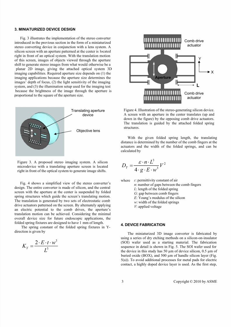
Fig. 4 shows a simplified view of the stereo converter’s
design. The entire converter is made of silicon, and the central
screen with the aperture at the center is suspended by folded
spring structures which guide the screen’s translating motion.
The translation is generated by two sets of electrostatic comb
drive actuators patterned on the screen. By alternately applying
an electric potential to the comb drives, the aperture’s
translation motion can be achieved. Considering the minimal
overall device size for future endoscopic applications, the
folded spring fixtures are designed to have 1 mm of length.
The spring constant of the folded spring fixtures in Y-
direction is given by
3
32
L
wt E K Y
⋅⋅⋅=
With the given folded spring length, the translating
distance is determined by the number of the comb fingers at the
actuators and the width of the folded springs, and can be
calculated by
2
3
3
4
V
w E g
Ln DY
⋅⋅⋅
⋅⋅=
ε
where
4. DEVICE FABRICATION
The miniaturized 3D image converter is fabricated by
using a series of dry etching methods on a silicon-on-insulator
(SOI) wafer used as a starting material. The fabrication
sequence in detail is shown in Fig. 5. The SOI wafer used for
the device in this study has 50 µm of device silicon, 0.5 µm o
buried oxide (BOX), and 500 µm of handle silicon layer (Fig
5(a)). To avoid additional processes for metal pads for electric
contact, a highly doped device layer is used. As the first step
Figure 4. Illustration of the stereo-generating silicon device.
A screen with an aperture in the center translates (up anddown in the figure) by the opposing comb drive actuators.
The translation is guided by the attached folded spring
structures.
L
Aperture
Comb driveactuator
Comb driveactuator
Y
X
Translating aperture
device
Objective lens
Figure 3. A proposed stereo imaging system. A silicon
microdevice with a translating aperture screen is located
right in front of the optical system to generate image shifts.
ɛ: permittivity constant of air
n: number of gaps between the comb fingers
L: length of the folded spring
G: gap between comb fingers
E : Young’s modulus of the silicon
w: width of the folded springs
V : applied voltage

8/6/2019 ASME IMECE2010 Submitted Final 2010-6-11
http://slidepdf.com/reader/full/asme-imece2010-submitted-final-2010-6-11 4/6
4 Copyright © 2010 by ASME
silicon dioxide layers are deposited on top and bottom of the
wafer by plasma enhanced chemical vapor deposition
(PECVD) method, followed by patterning those layers using
reactive ion etching (RIE) (Fig. 5(b)). After that, the silicon
handle layer is etched deeply (Fig. 5(c)) by using a deep
reactive ion etching (DRIE) or using an anisotropic wet etching
method (i.e., KOH etching). This step is to free the silicondevice layer on the top so that the patterned structure can move
freely, while the remaining thick structures in the handle layer
will be used to provide mechanical strength to certain areas on
the thin device layer at the points of electric contact. The device
layer with the aperture screen and the comb drive actuator is
then patterned by DRIE, followed by silicon dioxide layer
removal by RIE (Fig. 5(d)), finalizing the device fabrication.
The fabricated device is not only much simpler in
fabrication process with only two silicon etching steps, but also
much more robust compared to the flipping device with a thick
glass plate [12] because no heavy structures need to be
suspended by the folded springs, as shown in the final cross
section view (Fig. 5(d)).
5. DEVICE OPERATION
Fig. 6 (a) shows the fabricated silicon stereo converting
device. It is 5 mm in overall diameter and has an aperture 900
µm in diameter. The design with 150 moving comb fingers and
1 mm-long folded spring fixtures, among several variations
has been used for device tests in this study. The gap between
the opposing fingers is 3 µm. The device layer has been
patterned to form both signal and ground electrodes. For the
secure electrical connections, copper tapes were used to deliver
the driving and ground electric signals directly to each
electrode with silver paint brushed around the contact point between the tapes and the device electrodes.
Fig. 6 (b) and (c) are microscopic views of the white
dotted circle area in Fig. 6 (a), with ruler bars on the left with
10 µm increments. Fig. 6 (b) shows the comb drive actuator
with top stationary and bottom moving comb fingers when no
voltage is applied to the actuator, which is the initial finger
position as fabricated. Fig. 6 (c) shows the comb driv
actuation when 44 V is applied to the actuator, translating 60
µm of distance when 4 µm-wide folded spring is used.
Using the same device, up to 62 µm of screen translation
could be achieved at 45 V of applied voltage, as shown in Fig
7. When 5 µm-wide springs were used, up to 60 µm of finger
translation could be achieved at 58 V before some fingers
laterally touched each other. Even though 4 µm- and 5 µm-
wide folded spring fixtures were used, their translating motion
behaved like the ones with the slightly thinner spring widths
This was because of the tapering down of the 50 µm-thick
folded spring structures during the DRIE process, resulting in
the narrower spring bottom width than the top.
Figure 5. Process flow for the silicon stereo converter
device
Silicon
Oxide
Silicon
(b)
(c)
(a)
(d)
SOI as starting material
Oxide deposition and patterning
(Top and bottom surfaces)
Backside anisotropic etching
Frontside etching and oxide removal
Aperture Comb drive
Figure 6. (a) Photo of the fabricated silicon device 5 mm in
overall diameter. Microscopic views of the white dotted
circle area are shown in (b) and (c) during the comb drive
operation. (b) Initial comb finger location when no voltage
is applied, and (c) 60 µm of aperture translation when 44 V
is applied.
Moving fingers
Stationary fingers(b) (c)
5 m m
(a)
+
+
--

8/6/2019 ASME IMECE2010 Submitted Final 2010-6-11
http://slidepdf.com/reader/full/asme-imece2010-submitted-final-2010-6-11 5/6
5 Copyright © 2010 by ASME
6. VIEWING ANGLE CHANGES
A stereo system on a regular point-and-shoot camera (NV3,
Samsung Electronics) was built by attaching the fabricated
silicon device right in front of the camera lens. Additional
black screen material is attached in front of the silicon device to
block unnecessary light coming through the spring and comb
drive areas. Fig. 8 (a) shows a conventional 2D photo of a
LEGO® figure (without using the stereo converter) 4.5 cm in
height placed approximately 10 cm from the camera. The background is a hallway with doors at the end. Fig. 8 (b) and
(c) are photos taken with the camera optically zoomed to the
dotted square area shown in Fig. 8 (a) with the fabricated stereo
converter attached in the front. Keeping the camera focusing on
the doors during the experiment, the aperture screen translated
horizontally 50 µm each direction. As the aperture translated to
the left and right, the image of the LEGO® figure, which was
closer and not in focus, shifted to the right and left,
respectively, while the image of door at the end of the hallway
did not move.
The same silicon stereo converter was used for a
microscopic stereo imaging test as in Fig. 9, which shows the
images of a ruler covering approximately 3 cm captured at thetwo extrema aperture locations. As the aperture makes ±50 µm
horizontal translation, the distance between each marking on
the ruler expanded and contracted due to the slight change in
viewing angle. The microscope focused on the marking in the
middle (at 6.5 cm location), such that the image of that point
remains unmoved. As in these experiments, relative locations
or views from different angles of objects can be found by
observing the directions and the amount of each object’s image
shift.
CONCLUSIONS
Sets of stereo images can be used as a powerful tool to find
3D information when observing or inspecting an object by
providing depth information. This paper presented
microfabricated stereo imaging generator using a relatively
simple stereo imaging method with a single translatable
aperture. This miniaturized stereo converter was shown to
Figure 9. Recordedmicroscopic images of a
ruler viewed through the
translating aperture device.
As the aperture translates
±50 µm horizontally, the
width of each division on
the ruler changes (left) due
to the viewing angle
change, which is equivalent
to looking at the ruler from
two different angles
(above).
Figure 8. (a) 2D photo showing a LEGO® figure in the front
and a door in the back at the end of the hallway without thestereo converter attached. When the converter is attached
and the aperture translates left and right, the image of the
figure shifts (b) to the right and (c) left, respectively. For (b)
and (c), the camera focuses on the door in the back whose
image remains still.
(a) (b)
(c)
4 . 5 c m
3 µm-wide springcalculated
4 µm-wide springcalculated
4 µm-widespring tested
5 µm-wide springtested
5 µm-wide springcalculated
Applied voltage (V)
A p e r t u r e t r a n s l a t i o n ( µ m )
Figure 7. Aperture translation by comb drive actuators. 4µm and 5 µm-wide folded springs were used for the testing.
8/6/2019 ASME IMECE2010 Submitted Final 2010-6-11
http://slidepdf.com/reader/full/asme-imece2010-submitted-final-2010-6-11 6/6
6 Copyright © 2010 by ASME
successfully generate image shift when attached and operated
in front of imaging systems, even with the limited translating
distances microfabricated silicon actuators can provide. The
presented technique would be especially beneficial for
microscopic object inspection or endoscopic applications where
extraction of depth information from 2D images is more
challenging due to the relatively high axial depth of focuswithin the working distance of the device.
ACKNOWLEDGEMENTSThe project has been supported by the Small Business
Innovation Research (SBIR) grants from National Institutes of
Health (NIH). Authors want to thank Mr. James Jenkins for
valuable discussions and the input regarding the assembly of
the paper.
REFERENCES
[1] Zhang, R., Tsai, P., Cryer, J. E., and Shah, M., 1999, “Shape
from shading: A survey”, IEEE Transactions on Pattern
Analysis and Machine Intelligence, vol. 21, pp. 690-706.
[2] Saxena, A., Sun, M., and Ng, A. Y., 2007, “Learning 3-d
scene structure from a single still image”, in Proceedings of
IEEE International Conference on Computer Vision, pp. 1-8,
Rio de Janeiro, Brazil.
[3] Durrani, A. F. and Preminger, G. M., 1995, “Three-
dimensional video imaging for endoscopic surgery”,
Computers in Biology and Medicine, vol. 25, pp. 237-247.
[4] Schreier, H. W., Garcia, D., and Sutton, M. A., 2004,
“Advances in light microscope stereo vision”, Experimental
Mechanics, vol. 44, pp. 278-288.
[5] Okutomi, M. and Kanade, T., 1993, “A multiple-baseline
stereo”, IEEE transactions on Pattern Analysis and Machine
Intelligence, vol. 15, pp. 353-363.
[6] Goshtasby, A. and Gruver, W. A., 1993, “Design of a single-
lens stereo camera system", Pattern Recognition, vol. 26, pp.
923-937.
[7] Gao, C. and Ahuja, N., 2004, “Single camera stereo using
planar parallel plate”, in Proceedings of the International
Conference on Pattern Recognition, vol. 4, pp. 108-111,
Cambridge, UK.
[8] Lee, D. H. and Kweon, I. S., 2000, “A novel stereo camera
system by a biprism”, IEEE Transactions on Robotics and
Automation, vol. 16, pp. 528-541.
[9] Adelson, E. H. and Wang, J. Y. A., 1992, “Single lens stereo
with a plenoptic camera”, IEEE Transactions on Pattern
Analysis and Machine Intelligence, vol. 14, pp. 99-106.
[10] Seo, S., 2005, “Stereo-image capturing device”, US Paten
No. US 6,977,674 B2.
[11] Dou, Q. and Favaro, P., 2008, “Off-axis aperture camera
3d shape reconstruction and image restoration”, in Proceedings
of IEEE Conference on Computer Vision and Pattern
Recognition, pp. 1-7, Anchorage, USA.
[12] Choi, W., Akbarian, M., Rubtsov, V., and Kim, C.-J., 2009
“Microfabricated flipping glass disc for stereo imaging in
endoscopic visual inspection”, in Proceedings of IEEE
International Conference on Micro Electro Mechanica
Systems, pp. 160-163, Sorrento, Italy.