ashrae 90.1 compliant - lennoxpros.com · drainage requirements of ashrae 62.1. side drain...
TRANSCRIPT

P A C K A G E D E L E C T R I C / E L E C T R I C
MODEL NUMBER IDENTIFICATION
20 to 30 TonsNet Cooling Capacity − 238,000 to 354,000 Btuh
Optional Electric Heat - 30 to 120 kW
L C H 300 H 4 B S 1 YBrand/Family
L = Energence®
Unit Type C = Packaged Electric Cooling with optional Electric Heat
Major Design Sequence H = 1st Generation
Nominal Cooling Capacity - Tons 242 = 20 Tons 300 = 25 Tons 360 = 30 Tons
Refrigerant Type 4 = R-410A
Minor Design Sequence 1 = 1st Revision 2 = 2nd Revision 3 = 3rd Revision
Voltage Y = 208/230V-3 phase-60hz G = 460V-3 phase-60hz J = 575V-3 phase-60hz
Cooling Efficiency H = High Efficiency
ASHRAE 90.1COMPLIANT
LCHEnergence® Rooftop Units
60 HZBulletin No. 210608
July 2018 Supersedes September 2017
LCH 20-30 TON ROOFTOP UNITS
Blower Type B = Belt Drive, Constant Air Volume (CAV) M = MSAV® (Multi-Stage Air Volume) Belt Drive V = Variable Air Volume (VAV) Belt Drive
P R O D U C T S P E C I F I C AT I O N S
Factory Installed Electric Heat N = No Heat J = 30 kW Electric Heat K = 45 kW Electric Heat L = 60 kW Electric Heat P = 90 kW Electric Heat S = 120 kW Electric Heat

Energence® Packaged Electric / Electric 20 to 30 Ton / Page 2
Energence® rooftop units feature:
• Hinged Access Panels - Provide quick access to components and protect panels and roof from damage during servicing.
• Isolated Compressor Compartment - Allows performance check during normal compressor operation without disrupting airflow.
• Corrosion-Resistant Removable Drain Pan - Provides improved serviceability.• Thermostatic Expansion Valves - Provide peak cooling performance across the entire application range.• Scroll Compressors - Standard on all units for reliable, long-term operation.• Lennox’ Environ™ Coil System - Smaller, lighter condenser coil.• Constant Air Volume (CAV), Variable Air Volume (VAV) Blower Option or MSAV® (Multi-Stage Air
Volume) - Allows constant air, variable air or multi-staged air delivery. • Auto-Tensioner for Blower Belt - Factory option ensures blower is delivering the proper airflow for
comfort, while maximizing efficiency and belt life.• MERV 13 Filters - Available as factory or field option, provide an enhanced level of indoor air quality, and
can help the building qualify for additional LEED credits.• Foil-Faced Insulation - Insulation on all internal surfaces that have contact with airflow helps minimize
airborne fibers and improve IAQ.• Common Components - Many maintenance items are standard throughout the entire product line,
reducing the need to carry different parts to the job or maintain in inventory.Prodigy® Control System Standard on every Energence® rooftop unit, the new Prodigy® 2.0 unit controller is the heart of the Lennox® controls offering. The intuitive user interface makes setup, troubleshooting and service easier than ever. Each unit tracks the runtime of every major component and records the date and time when service or maintenance is performed.
SmartWire™ SystemThe SmartWire system simplifies field sensor or thermostat installation through advanced connectors that are keyed and color-coded to help prevent miswiring. Not only is the wire coloring scheme standardized across all models, each connection is intuitively labeled to make troubleshooting and servicing quick and easy.
FEATURES AND BENEFITS
APPROVALS242 models are AHRI Certified to AHRI Standard 340/360-2015.300 and 360 models are tested at conditions included in AHRI Standard 340/360-2015.ETL listed.Components bonded for grounding to meet safety standards for servicing required by UL, ULC and National and Canadian Electrical Codes.All models are ASHRAE 90.1 compliant.All models meet DOE 2018 energy efficiency standards.MSAV® models meet California Code of Regulations, Title 24 requirements for staged airflow.Energy Star® certified units are designed to use less energy, help save money on utility bills, and help protect the environment.The Energy Star® Partner of the Year Award signifies that Lennox has made outstanding contributions to design energy efficient units that will lower energy bills, while meeting industry standards for comfort and indoor air quality. Lennox was the first HVAC manufacturer to win this award and has been a four-time recipient since 2003.ISO 9001 Registered Manufacturing Quality System.
A
Lennox’ Energence® packaged rooftop unit product line was created to save energy with intelligence by offering some of the highest energy efficiency ratings available with a powerful, easy to use unit controller. This makes Energence® rooftop units perfect for business owners looking for an HVAC product with the lowest total cost of ownership.
B
D E
C
F
G
H
I
J
K
L
M
N
O

Energence® Packaged Electric / Electric 20 to 30 Ton / Page 3
FEATURES AND BENEFITS
APPROVALS242 models are AHRI Certified to AHRI Standard 340/360-2015.300 and 360 models are tested at conditions included in AHRI Standard 340/360-2015.ETL listed.Components bonded for grounding to meet safety standards for servicing required by UL, ULC and National and Canadian Electrical Codes.All models are ASHRAE 90.1 compliant.All models meet DOE 2018 energy efficiency standards.MSAV® models meet California Code of Regulations, Title 24 requirements for staged airflow.Energy Star® certified units are designed to use less energy, help save money on utility bills, and help protect the environment.The Energy Star® Partner of the Year Award signifies that Lennox has made outstanding contributions to design energy efficient units that will lower energy bills, while meeting industry standards for comfort and indoor air quality. Lennox was the first HVAC manufacturer to win this award and has been a four-time recipient since 2003.ISO 9001 Registered Manufacturing Quality System.
A
WARRANTYLimited five years on compressors.Limited three years on the Lennox’ Environ™ Coil System.Limited three years on Prodigy® 2.0 unit controller.Limited five years Optional High Performance Economizers.Limited one year all other covered components.
COOLING SYSTEMDesigned to maximize sensible and latent cooling performance at design conditions.System can operate from 0°F to 125°F without any additional controls.
R-410A Refrigerant Non-chlorine based, ozone friendly, R-410A.
Scroll CompressorsScroll compressors on all models for high performance, reliability and quiet operation.Resiliently mounted on rubber grommets for quiet operation.
Compressor Crankcase HeatersProtects against refrigerant migration that can occur during low ambient operation.
B
Lennox’ Environ™ Coil System Condenser coil features lightweight, all aluminum brazed fin construction.Constructed of three components: a flat extrusion tube, fins in-between the flat extrusion tube and two refrigerant manifolds.Environ™ System Features:• Improved heat transfer
performance due to high primary surface area (flat tubes) versus secondary surface (fins).
• Smaller internal volume (reduced refrigerant charge).
• High durability (all aluminum construction).
• Fewer brazed joints.• Compact design (reduces unit
weight).• Easy maintenance/cleaning.Face split design.Mounting brackets with rubber inserts secure coil to unit providing vibration dampening and corrosion protection.Angled design in cabinet helps protect coil from possible contact or hail damage.
Evaporator CoilCopper tube construction, enhanced rippled-edge aluminum fins, flared shoulder tubing connections, silver soldered construction for improved heat transfer. Factory leak tested. Cross row circuiting with rifled tubing optimizes both sensible and latent cooling capacity. Low fin per inch count minimizes air pressure drop.Constant air volume (CAV) models have face-split evaporator coils designed to keep condensate water off of an inactive part of the coil so the condensate will not re-enter the air stream.Variable air volume (VAV) and MSAV® (Multi-Stage Air Volume) models have row-split evaporator coils.
CCONTENTSBlower Data . . . . . . . . . . . . . . . . . . . . . . . . . . . . . . . . .28Dimensions - Accessories. . . . . . . . . . . . . . . . . . . . . . . . . .50Dimensions - Unit . . . . . . . . . . . . . . . . . . . . . . . . . . . . . .49Electrical Accessories. . . . . . . . . . . . . . . . . . . . . . . . . . . .42Electrical Data. . . . . . . . . . . . . . . . . . . . . . . . . . . . . . . .32Features And Benefits . . . . . . . . . . . . . . . . . . . . . . . . . . . 2Model Number Identification . . . . . . . . . . . . . . . . . . . . . . . . 1Optional Conventional Temperature Control Systems . . . . . . . . . . .46Options / Accessories . . . . . . . . . . . . . . . . . . . . . . . . . . . .17Outdoor Sound Data . . . . . . . . . . . . . . . . . . . . . . . . . . . .48Prodigy® Control System . . . . . . . . . . . . . . . . . . . . . . . . . . 7Ratings . . . . . . . . . . . . . . . . . . . . . . . . . . . . . . . . . . .23Sequence Of Operation. . . . . . . . . . . . . . . . . . . . . . . . . . .11Specifications . . . . . . . . . . . . . . . . . . . . . . . . . . . . . . . .21Unit Clearances . . . . . . . . . . . . . . . . . . . . . . . . . . . . . . .44Weight Data . . . . . . . . . . . . . . . . . . . . . . . . . . . . . . . . .48
Energence® Packaged Electric / Electric 20 to 30 Ton / Page 4
FEATURES AND BENEFITS
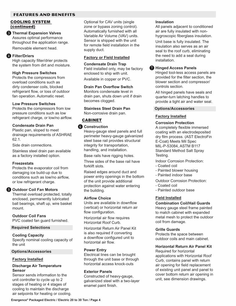
COOLING SYSTEM (continued)Thermal Expansion ValvesAssures optimal performance throughout the application range.Removable element head.
Filter/DriersHigh capacity filter/drier protects the system from dirt and moisture.
High Pressure SwitchesProtects the compressors from overload conditions such as dirty condenser coils, blocked refrigerant flow, or loss of outdoor fan operation. Automatic reset.
Low Pressure SwitchesProtects the compressors from low pressure conditions such as low refrigerant charge, or low/no airflow.
Condensate Drain PanPlastic pan, sloped to meet drainage requirements of ASHRAE 62.1.Side drain connections.Stainless steel drain pan available as a factory installed option.
FreezestatsProtects the evaporator coil from damaging ice build-up due to conditions such as low/no airflow, or low refrigerant charge.
Outdoor Coil Fan MotorsThermal overload protected, totally enclosed, permanently lubricated ball bearings, shaft up, wire basket mount.
Outdoor Coil FansPVC coated fan guard furnished.
Required Selections
Cooling CapacitySpecify nominal cooling capacity of the unit
Options/Accessories
Factory InstalledDischarge Air Temperature SensorSensor sends information to the unit controller to cycle up to 2 stages of heating or 4 stages of cooling to maintain the discharge air setpoints for heating or cooling.
D
E
F
Optional for CAV units (single zone or bypass zoning control). Automatically furnished with all Variable Air Volume (VAV) units. Sensor is shipped with the unit for remote field installation in the supply duct.
Factory or Field InstalledCondensate Drain TrapField installed only, may be factory enclosed to ship with unit.Available in copper or PVC.
Drain Pan Overflow SwitchMonitors condensate level in drain pan, shuts down unit if drain becomes clogged.
Stainless Steel Drain PanNon-corrosive drain pan.
CABINETConstructionHeavy-gauge steel panels and full perimeter heavy-gauge galvanized steel base rail provides structural integrity for transportation, handling, and installation.Base rails have rigging holes.Three sides of the base rail have forklift slots.Raised edges around duct and power entry openings in the bottom of the unit provide additional protection against water entering the building.
Airflow ChoiceUnits are available in downflow (vertical) or horizontal return air flow configuration.Horizontal air flow requires Horizontal Roof Curb.Horizontal Return Air Panel Kit is also required if converting a downflow configured unit to horizontal air flow.
Power EntryElectrical lines can be brought through the unit base or through horizontal access knock-outs
Exterior PanelsConstructed of heavy-gauge, galvanized steel with a two-layer enamel paint finish.
G
InsulationAll panels adjacent to conditioned air are fully insulated with non-hygroscopic fiberglass insulation.Unit base is fully insulated. The insulation also serves as an air seal to the roof curb, eliminating the need to add a seal during installation.
Hinged Access PanelsHinged tool-less access panels are provided for the filter section, the blower section and compressor/controls section.All hinged panels have seals and quarter-turn latching handles to provide a tight air and water seal.
Options/Accessories
Factory InstalledCorrosion ProtectionA completely flexible immersed coating with an electrodeposited dry film process. (AST ElectroFin E-Coat) Meets Mil Spec MIL-P-53084, ASTM B117 Standard Method Salt Spray Testing.Indoor Corrosion Protection: - Coated coil - Painted blower housing - Painted indoor baseOutdoor Corrosion Protection: - Coated coil - Painted outdoor base
Field InstalledCombination Coil/Hail GuardsHeavy gauge steel frame painted to match cabinet with expanded metal mesh to protect the outdoor coil from damage.
Grille GuardsProtects the space between outdoor coils and main cabinet.
Horizontal Return Air Panel KitRequired for horizontal applications with Horizontal Roof Curb, contains panel with return air opening for field replacement of existing unit panel and panel to cover bottom return air opening in unit, see dimension drawings.
H
Energence® Packaged Electric / Electric 20 to 30 Ton / Page 5
FEATURES AND BENEFITS
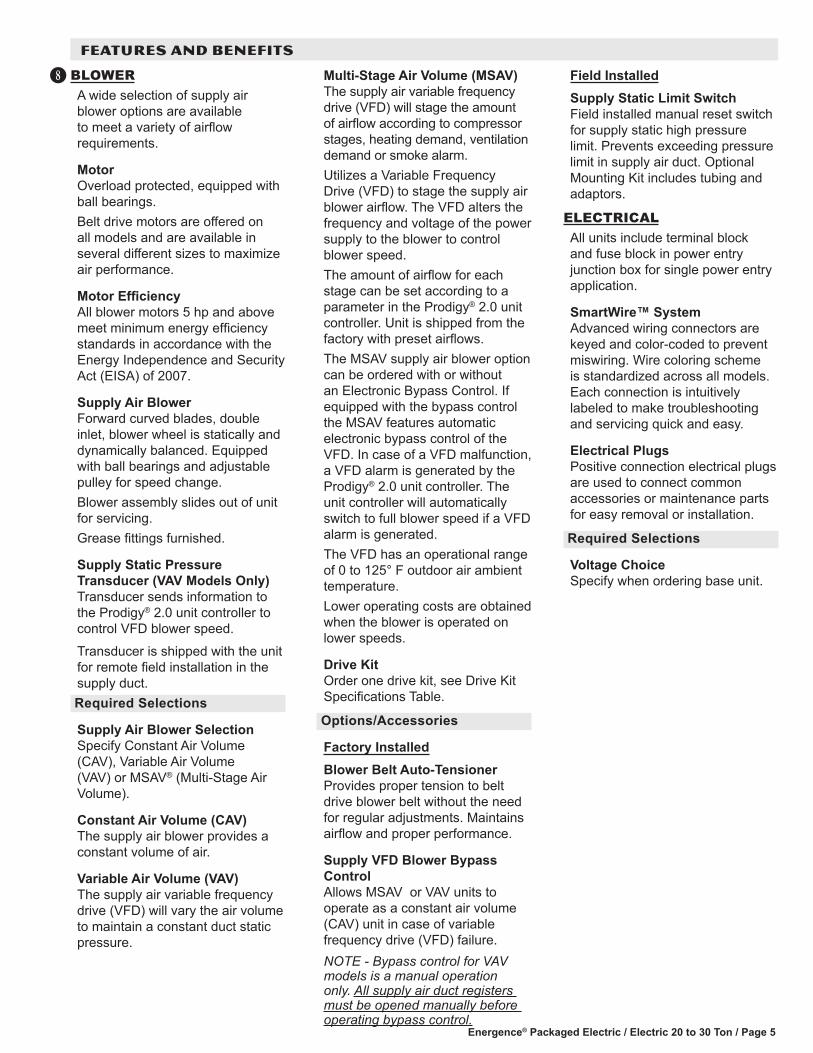
BLOWERA wide selection of supply air blower options are available to meet a variety of airflow requirements.
MotorOverload protected, equipped with ball bearings.Belt drive motors are offered on all models and are available in several different sizes to maximize air performance.
Motor EfficiencyAll blower motors 5 hp and above meet minimum energy efficiency standards in accordance with the Energy Independence and Security Act (EISA) of 2007.
Supply Air BlowerForward curved blades, double inlet, blower wheel is statically and dynamically balanced. Equipped with ball bearings and adjustable pulley for speed change.Blower assembly slides out of unit for servicing.Grease fittings furnished.
Supply Static Pressure Transducer (VAV Models Only) Transducer sends information to the Prodigy® 2.0 unit controller to control VFD blower speed.Transducer is shipped with the unit for remote field installation in the supply duct.Required Selections
Supply Air Blower SelectionSpecify Constant Air Volume (CAV), Variable Air Volume (VAV) or MSAV® (Multi-Stage Air Volume).
Constant Air Volume (CAV)The supply air blower provides a constant volume of air.
Variable Air Volume (VAV)The supply air variable frequency drive (VFD) will vary the air volume to maintain a constant duct static pressure.
I Multi-Stage Air Volume (MSAV)The supply air variable frequency drive (VFD) will stage the amount of airflow according to compressor stages, heating demand, ventilation demand or smoke alarm.Utilizes a Variable Frequency Drive (VFD) to stage the supply air blower airflow. The VFD alters the frequency and voltage of the power supply to the blower to control blower speed.The amount of airflow for each stage can be set according to a parameter in the Prodigy® 2.0 unit controller. Unit is shipped from the factory with preset airflows. The MSAV supply air blower option can be ordered with or without an Electronic Bypass Control. If equipped with the bypass control the MSAV features automatic electronic bypass control of the VFD. In case of a VFD malfunction, a VFD alarm is generated by the Prodigy® 2.0 unit controller. The unit controller will automatically switch to full blower speed if a VFD alarm is generated.The VFD has an operational range of 0 to 125° F outdoor air ambient temperature.Lower operating costs are obtained when the blower is operated on lower speeds.
Drive KitOrder one drive kit, see Drive Kit Specifications Table.
Options/Accessories
Factory InstalledBlower Belt Auto-TensionerProvides proper tension to belt drive blower belt without the need for regular adjustments. Maintains airflow and proper performance.
Supply VFD Blower Bypass ControlAllows MSAV or VAV units to operate as a constant air volume (CAV) unit in case of variable frequency drive (VFD) failure.NOTE - Bypass control for VAV models is a manual operation only. All supply air duct registers must be opened manually before operating bypass control.
Field InstalledSupply Static Limit SwitchField installed manual reset switch for supply static high pressure limit. Prevents exceeding pressure limit in supply air duct. Optional Mounting Kit includes tubing and adaptors.
ELECTRICALAll units include terminal block and fuse block in power entry junction box for single power entry application.
SmartWire™ SystemAdvanced wiring connectors are keyed and color-coded to prevent miswiring. Wire coloring scheme is standardized across all models. Each connection is intuitively labeled to make troubleshooting and servicing quick and easy.
Electrical PlugsPositive connection electrical plugs are used to connect common accessories or maintenance parts for easy removal or installation.
Required Selections
Voltage ChoiceSpecify when ordering base unit.

Energence® Packaged Electric / Electric 20 to 30 Ton / Page 6
FEATURES AND BENEFITS
ELECTRICAL (continued)
Options/Accessories
Factory InstalledCircuit BreakersHACR type. For overload and short circuit protection. Factory wired and mounted in the power entry panel. Current sensitive and temperature activated. Manual reset.
SCR (Silicon Controlled Rectifier) Electric Heat ControlThe SCR Electric Heat Control modulates small, precise increments of power to the electric heat load eliminating temperature fluctuations associated with mechanical controls.Almost instantaneous operation with no moving parts.Zero-Cross (fast cycling) feature improves electric heater life with less contraction and expansion of the heating elements.The SCR operates when there is no call for heat from the building control system or thermostat. SCR air tempering is controlled by a secondary thermostat and remote duct sensor (ordered separately). A call for heat overrides the SCR and modulates the SCR to 100% heat output. A call for cooling overrides the SCR.NOTE - The SCR option is not available with 45 kW, 60 kW and 90kW electric heat (208/230V) models.NOTE - Blower Proving Switch is required and must be ordered separately for factory installation. See Controls in the Options/Accessories table.NOTE - Available for use with conventional thermostat controls or Novar® control systems only.
Phase/Voltage DetectionPhase detection monitors power supply to assure phase is correct at unit start-up. If phase is incorrect, the unit will not start and an alarm code is reported to the unit controller. Protects unit from being started with incorrect phasing which could lead to issues such as compressors running backwards.
Voltage detection monitors power supply voltage to assure proper voltage. If voltage is not correct (over/under voltage conditions) the unit will not start and an alarm code is reported to the unit controller.NOTE - Phase/voltage detection is furnished when the MSAV® (Multi-Stage Air Volume) or VAV (Variable Air Volume) option is ordered.
Factory or Field InstalledDisconnect SwitchAccessible from outside of unit, spring loaded weatherproof cover furnished.
Electric HeatHelix wound nichrome elements, individual element limit controls, wiring harness. Unit fuse block is furnished as standard. See Options / Accessories tables for ordering information.
GFI Service Outlets (2)115V ground fault circuit interrupter (GFCI) type, non-powered, field-wired or factory-wired and powered.
Field InstalledGFI Weatherproof CoverSingle-gang cover.Heavy-duty UV-resistant polycarbonate case construction.Hinged base cover with gasket.
INDOOR AIR QUALITYAir FiltersDisposable 2 inch filters furnished as standard.
Options/Accessories
Factory InstalledHealthy Climate® UVC Germicidal Light Kit
Germicidal lamps emit ultra-violet (UV-C) energy, which has been proven to be effective in reducing microbes such as viruses, bacteria,
J
K
yeasts, and molds. This process either destroys the organism or controls its ability to reproduce.UV-C energy greatly reduces the growth and proliferation of mold and other bioaerosols (bacteria and viruses) on illuminated surfaces (particularly coil and drain pan).Lamps are field installed in the blower/evaporator coil section.All necessary hardware for installation is included.Lamps operate on 110/230V, single phase power supply. Step-down transformer is furnished with lamps when used with 460V and 575V rooftop units. Approved by ETL.
Factory or Field InstalledHealthy Climate® High Efficiency Air FiltersDisposable MERV 8 or MERV 13 (Minimum Efficiency Reporting Value based on ASHRAE 52.2) efficiency 2 inch pleated filters.
Replacement Filter Media Kit With FrameReplaces existing pleated filter media. Includes washable metal mesh screen and metal frame with clip for holding replaceable non-pleated filter.
Field InstalledIndoor Air Quality (CO2) SensorsMonitors CO2 levels, reports to the Prodigy® unit controller which adjusts economizer dampers as needed.

Energence® Packaged Electric / Electric 20 to 30 Ton / Page 7
PRODIGY 2.0 UNIT CONTROLLER
The Prodigy 2.0 unit controller is a microprocessor-based controller that provides flexible control of all unit functions.
Features:LCD Display - Easy to read menu with buttons for menu navigation.during setup and diagnostics. 4 lines x 20 character display.Menu LEDs - Four LEDs (Data, Setup, Service, Settings) aid in menu navigation.Main Menu and Help Buttons - Quick navigation to home screen and built-in help functions.Scroll, Value Adjustment Select and Save ButtonsSimplified Setup Procedure - SETUP menu insures proper installation and setup of the rooftop unit.Profile Setup - Copy key settings between units with the same configuration greatly reducing setup time.USB Port - Allows a technician to download and transfer unit information to help verify service was performed. USB drive will also allow updating software on the Prodigy Control System to obtain enhanced functionality without the need to change components.Unit Controller SoftwareUnit Self-Test - Unit Controller can perform a rooftop unit self-test to verify individual critical component and system performance. Included is an economizer test function that helps assure the economizer is operating correctly.Time Clock with Run-time InformationBuilt-In Functions Include:Adjustable Blower On/Off DelayBuilt-in Control Parameter DefaultsCompressor Time-Off Delay
L
PRODIGY® CONTROL SYSTEM
DDC CompatibleDirty Filter Switch InputDischarge Air Temperature ControlDisplay/Sensor ReadoutEconomizer Control Options - See Economizer / Outdoor Air / Exhaust Options.Fresh Air TemperingExtensive Unit Diagnostics - Over 100 diagnostic and status messages in English.Exhaust Fan Control Modes - Fresh air damper position, differential pressure transducer or pressure switches.Permanent Diagnostic Code StorageField Adjustable Control Parameters - Over 200 different control settings.Indoor Air Quality Input - Demand Control Ventilation readyLow Ambient Controls - Cooling operation down to 0°F.Gas Valve Time Delay Between First and Second StageMinimum Compressor Run TimeNetwork Capable - Can be daisy chained to other units or controls.Night Setback ModeReturn Air Temperature Limit ControlSafety Switch Input - Allows Controller to respond to a external safety switch trip.Service Relay OutputSmoke Alarm Mode - Four choices (unit off, positive pressure, negative pressure, purge).Staging - Up to 2 heat/2 cool (standard Prodigy 2.0 unit controller thermostat input). Up to 3 cool with additional relay. Up to 4 cool with room sensor or network operation.“Strike Three” Protection
Gas Reheat Control - Simultaneous heating and cooling operation for controlling humidity for process air applications such as supermarkets.On Demand Dehumidification - Monitors and controls condenser hot gas reheat operation with Humiditrol® option.Thermostat Bounce DelayWarm Up Mode DelayLED IndicatorsPC Interface - Connect to the Prodigy 2.0 unit controller from a PC with the Lennox Unit Controller Software.Room Sensor Operation - Controls temperature.Controls Options
Factory or Field InstalledFresh Air TemperingUsed in applications with high outside air requirements. The Controller energizes the first stage heat as needed to maintain a minimum supply air temperature for comfort, regardless of the thermostat demand. When ordered as a factory option, the sensor ships with the unit but must be field installed.
Smoke DetectorPhotoelectric type, installed in supply air section, return air section or both sections. Available with power board and single sensor (supply or return) or power board and two sensors (supply and return). Power board located in unit control compartment.
Interoperability via BACnet® or LonTalk® ProtocolsCommunication compatible with third-party automation systems that support the BACnet Application Specific Controller device profile, LonMark® Space Comfort Controller functional profile, or LonMark Discharge Air Controller functional profile.
NOTE - Prodigy® Control System features shown vary with the type of rooftop unit the control is installed in.NOTE - See separate Prodigy® Control System Control System Product Specifications Bulletin for additional information.

Energence® Packaged Electric / Electric 20 to 30 Ton / Page 8
OPTIONS / ACCESSORIES
Standard Economizer Features (Not for Title 24)Gear-driven action, return air and outdoor air dampers, plug-in connections to unit, nylon bearings, neoprene seals, 24-volt, fully-modulating spring return motor, adjustable minimum damper position.NOTE: The Free Cooling default setting for outdoor air temperature sensor is 55°F.
High Performance Economizer Features Approved for California Title 24 building standards. Low leakage dampers are Air Movement and Control Association International (AMCA) Class 1A Certified - Maximum 3 CFM per sq. ft. leakage at 1 in. w.g.ASHRAE 90.1 compliant.Gear-driven action, high torque 24-volt fully-modulating spring return damper motor, return air and outdoor air dampers, plug-in connections to unit, stainless steel bearings, enhanced neoprene blade edge seals and flexible stainless steel jamb seals to minimize air leakage.NOTE - High Performance Economizers are not approved for use with enthalpy controls in Title 24 applications.
Differential Sensible ControlFactory setting. Uses outdoor air and return air sensors that are furnished with the unit. The Prodigy® 2.0 unit controller compares outdoor air and return air and using setpoints, enables the economizer when the outdoor air temperature is below the configured setpoint and cooler than return air.NOTE - Differential Sensible Control can be configured in the field to provide Offset Differential Sensible Control or Single Sensible Control.
PRODIGY 2.0 UNIT CONTROLLER (continued)
Controls Options (continued)
L Connection® Network Control SystemComplete building automation control system for single or multi-zone applications. Options include local interface, software for local or remote communication, and hardware for networking other control functions. See L Connection Network Control System Product Specifications Bulletin for details.
Commercial Control SystemsAftermarket DDCNovar® ETM modules and options.ThermostatsControl system and thermostat options. Aftermarket unit controller options.
Field InstalledGeneral Purpose Control KitPlug-in control provides additional analog and digital inputs/outputs for field installed options.
ECONOMIZER OPTIONSEconomizer operation is set and controlled by the Prodigy® 2.0 unit controller.Simple plug-in connections from economizer to unit controller for easy installation.All Energence® rooftop units are equipped with factory installed CEC Title 24 approved sensors for outside, return and discharge air temperature monitoring.Optional sensors may be used instead of unit sensors to determine whether outdoor air is suitable for free cooling. See Options/Accessories table.
Factory or Field InstalledEconomizer Features (Standard and High Eficiency)Outdoor air hoods for economizer dampers furnished.Outdoor Air Hood is included when economizer is factory installed and is furnished with economizer when ordered for field installation.
M
In Offset Differential Sensible Control mode, the economizer is enabled if the temperature differential (offset) between outdoor air and return air reaches the configured setpoint. In Single Sensible Control mode, the economizer is enabled when outdoor air temperature falls below the configured setpoint.
Global ControlThe unit controller communicates with a DDC system with one global sensor (enthalpy or sensible) to determine whether outside air is suitable for free cooling on all units connected to the control system. Sensor must be field provided.NOTE - Global control with enthalpy is not approved for Title 24 applications.
Factory or Field InstalledSingle Enthalpy Temperature Control (Not for Title 24)Outdoor air enthalpy sensor enables Economizer if the outdoor enthalpy is less than the setpoint of the control.
Differential Enthalpy Control (Not for Title 24)Order two Single Enthalpy Controls. One is field installed in the return air section, the other in the outdoor air section. Allows the economizer control to select between outdoor air or return air, whichever has lower enthalpy.
Outdoor Air CFM ControlMaintains constant outdoor air CFM levels for VAV units with variable frequency drives on the supply fan and varying unit airflows. Using information from a velocity sensor located in the units’ outdoor air section, the Prodigy® 2.0 unit controller changes the economizer position to help minimize the effect of supply fan speed changes on outdoor air CFM levels. Setpoint for outdoor air CFM is established by field testing. NOTE - Not available with Demand Control Ventilation (CO2 Sensor).

Energence® Packaged Electric / Electric 20 to 30 Ton / Page 9
ECONOMIZER OPTIONS (continued)
Field InstalledBuilding Pressure ControlMaintains constant building pressure level.Includes a static pressure transducer and outdoor static pressure assembly.Using differential pressure information between the outdoor air and the building air, the Prodigy® 2.0 unit controller changes the economizer position to help maintain a constant building pressure.NOTE - Not available with Demand Control Ventilation (CO2 Sensor) or Outdoor Air CFM Control.
EXHAUST OPTIONS
Factory or Field InstalledDownflow Barometric Relief DampersAllow relief of excess air, aluminum blade dampers prevent blow back and outdoor air infiltration during off cycle, bird screen furnished.Hood for downflow barometric relief dampers is factory installed when dampers are factory installed with economizer. Hood is furnished with dampers when ordered for field installation.
Standard Static Power ExhaustThree, 1/3 hp motors with 20 in., five blade propeller-type fans with a total power input of 1125 Watts and a total air volume of 12,800 cfm at 0 in. w.g. Motor is inherently protected and enclosed for maximum protection from weather, dust and corrosion. Installs internal to unit for downflow applications only with economizer option, provides exhaust air pressure relief, interlocked to run when return air dampers are closed and supply air blower is operating, fans run based on air damper position (adjustable), motor is overload protected, steel cabinet and hood painted to match unit, requires optional Downflow Economizer Barometric Relief Dampers. See Standard Static
N
O
Power Exhaust Blower Tables.
Horizontal Barometric Relief DampersFor use when unit is configured for horizontal applications requiring an economizer.Allows relief of excess air.Aluminum blade dampers prevent blow back and outdoor air infiltration during off cycle.Field installed in return air duct.Bird screen and hood furnished.Horizontal Economizer Conversion kit is available for field installation.
Field InstalledHigh Static Power ExhaustChoice of 50% (two, 2 hp motors) or 100% (three, 2 hp motors) centrifugal-type power exhaust blowers. Overload and sub-fuse protected, equipped with ball bearings. Forward curved blades, blower wheel is statically and dynamically balanced. Constant volume high static power exhaust blowers have adjustable pulleys for speed adjustments and are controlled by damper position. VAV/MSAV units can be ordered with High Static Power Exhaust (with VFD) and an optional factory installed Manual Supply VFD Blower Bypass for the Power Exhaust VFD’s (see page 5).High Static Power Exhaust (with VFD) features a solid-state analog pressure transducer control which senses differential pressure between conditioned space and outdoor air to regulate exhaust blower speed.See High Static Power Exhaust Blower Tables.NOTE - High Static Power Exhaust is field installed but must be ordered at the same time as the rooftop unit so the unit can be factory configured for this option.
Power Exhaust Control Options:Damper Position ControlFor Standard or High Static Power Exhaust without VFD. Prodigy® 2.0 unit controller controls the power exhaust based on economizer damper position.
Differential Pressure TransducerFor High Static Power Exhaust with VFD. Prodigy® 2.0 unit controller controls the power exhaust system based on a 0-10VDC signal from a differential pressure transducer which compares atmospheric pressure to conditioned space static pressure. The transducer is factory installed in the power exhaust section.
Field InstalledPressure SwitchFor Standard or High Static Power Exhaust without VFD, Prodigy® 2.0 unit controller controls the power exhaust system based on one or two pressure switch(es).NOTE - Order one per unit with Standard or High Static Power Exhaust without VFD.NOTE - Order two per unit with Standard Static Power Exhaust for MSAV or VAV models.
OPTIONS / ACCESSORIES

Energence® Packaged Electric / Electric 20 to 30 Ton / Page 10
OPTIONS / ACCESSORIES
OUTDOOR AIR OPTIONS
Factory or Field InstalledOutdoor Air Damper - Downflow or Horizontal With Air HoodLinked mechanical dampers, 0 to 25% (fixed) outdoor air adjustable, installs in unit. Includes outdoor air hood.Automatic model features fully modulating spring return damper motor with plug-in connection.Manual model features parallel blade, gear-driven dampers with adjustable fixed position.Minimum mixed air temperature in heating mode is 30°F. Maximum mixed air temperature in cooling mode is 90°F.
ROOF CURBSNailer strip furnished (downflow only), mates to unit, US National Roofing Contractors Approved, shipped knocked down.
DownflowHybrid Roof CurbsRoof curb can be assembled using interlocking tabs to fasten corners together. No tools required.Curb can also be fastened together with furnished hardware.Available in 14, 18, and 24 inch heights.See Options/Accessories table.
HorizontalConverts unit from downflow to horizontal (side) air flow, return air is on unit, supply air is on curb, see dimension drawings.Requires Horizontal Return Air Panel Kit.Available in 37 inch and 41 inch heights.Optional Insulation Kit is available to help prevent sweating.
CEILING DIFFUSERSCeiling Diffusers (Flush or Step-Down)Diffuser face and grilles with white powder coat finish, insulated (UL listed duct liner), diffuser box with collars for duct connection, fixed blades (flush diffusers) and double deflection blades (step-down diffusers), provisions for suspending, internally sealed (prevents recirculation), removable return air grille, adapts to T-bar ceiling grids or plaster ceilings.
Transitions (Supply and Return)Used with diffusers, installs in roof curb, galvanized steel construction, flanges furnished for duct connection to diffusers, fully insulated.

Energence® Packaged Electric / Electric 20 to 30 Ton / Page 11
SEQUENCE OF OPERATION
Objective: Outline the unit functions as a result of room thermostat or room sensor demands.Given: When economizer is present, it will function as an integral part of the unit cooling system. When not present, unit will function as if economizer is present but outdoor ambient is high and sensed as not suitable.
CAV Units with 2-Stage Thermostat or Third Party Unit Controllers (2 Heat / 2 Cool) (This section not applicable for Discharge Air Temperature control)
SUPPLY AIR BLOWER SPEEDUnit has one blower speed for all modes of operation.
COOLING MODE (2 Cool)1 UNIT FEATURES AN ECONOMIZER AND OUTDOOR AIR IS SUITABLEY1 Demand - All compressors are off, supply air blower is on; economizer modulates (minimum to maximum open
position) to satisfy thermostat demand.Y2 Demand - All compressors are off, supply air blower is on, and economizer modulates (minimum to maximum open
position) to maintain 55ºF discharge air temperature.NOTE - If economizer stays at maximum open for 3 minutes, compressors 1 and 2 are energized with the supply air blower on, providing maximum cooling capacity.NOTE - The thermostat or third party unit controller has direct control over the rooftop unit’s staging capability. While the unit controller typically has direct control over the economizer, it is possible for a thermostat or third party unit controller to directly control this functionality1 Outdoor air suitability is determined by the energy state of outdoor ambient (enthalpy or sensible) and its ability to
achieve the desired free cooling effects. Outdoor air suitability can also be determined by a third party controller and provided to the RTU via a network connection.
UNIT DOES NOT FEATURE AN ECONOMIZER OR OUTDOOR AIR IS NOT SUITABLEY1 Demand - The first two compressors operate and the supply air blower is activated. This is ~50% of the cooling
capacity.Y2 Demand - All compressors operate and supply air blower is activated. This is 100% of the cooling capacity.HEATING MODE (2 Heat)NOTE - HEATING MODE IS THE SAME FOR ALL CONTROL OPTIONS.W1 Demand - 1st stage electric heat is energized and the supply air blower operates at heating speed.W2 Demand - 2nd stage electric heat is energized and the supply air blower operates at heating speed (45, 60, 90 or 120 kW electric heat option only).

Energence® Packaged Electric / Electric 20 to 30 Ton / Page 12
SEQUENCE OF OPERATION
CAV Units Operating in Room Sensor Mode or Discharge Air Temperature Control (4 Heat / 4 Cool)
SUPPLY AIR BLOWER SPEEDUnit has one blower speed for all modes of operation.
COOLING MODE (4 Cool)Room sensors (when connected to S-Bus) or Discharge air temperature (DAT) can be used to control unit staging.• DAT default setpoint = 55ºF. Unit will stage compressors as required to maintain the setpoint when provided
with Y1 thermostat demand.• Room sensor occupied default setpoint = 75ºF. Unit will stage compressors as required to maintain the
setpoint.• Increasing compressor stages provides more cooling capacity while decreasing compressor stages provides
less cooling capacity.1 UNIT FEATURES AN ECONOMIZER AND OUTDOOR AIR IS SUITABLECooling Stage 1 - All compressors are off, supply air blower is on; economizer modulates (minimum to maximum open
position) to maintain setpoint.Cooling Stage 2 - One compressor is activated; supply air blower is on; economizer modulates (minimum to
maximum open position) to maintain setpoint.Cooling Stage 3 - Two compressors are activated; supply air blower is on; economizer modulates (minimum to
maximum open position) to maintain setpoint.Cooling Stage 4 - All compressors are activated; supply air blower is on; economizer modulates (minimum to
maximum open position) to maintain setpoint. NOTE - The thermostat or third party unit controller has direct control over the rooftop unit’s staging capability. While the unit controller typically has direct control over the economizer, it is possible for a thermostat or third party unit controller to directly control this functionality1 Outdoor air suitability is determined by the energy state of outdoor ambient (enthalpy or sensible) and its ability to
achieve the desired free cooling effects. Outdoor air suitability can also be determined by a third party controller and provided to the RTU via a network connection.
UNIT DOES NOT FEATURE AN ECONOMIZER OR OUTDOOR AIR IS NOT SUITABLECooling Stage 1 - The first compressor is activated; supply air blower is on. This is ~25% of the cooling capacity.Cooling Stage 2 - The first and second compressors are activated; supply air blower is on. This is ~50% of the cooling
capacity.Cooling Stage 3 - The first three compressors are activated; supply air blower is on. This is ~75% of the cooling
capacity.Cooling Stage 4 - All compressors operate and supply air blower is activated. This is 100% of the cooling capacity.HEATING MODE (4 Heat)Room sensors (when connected to S-Bus) or Discharge air temperature (DAT) can be used to control up to four stgaes of electrc heat. • DAT default setpoint = 110ºF. Unit will stage heating as required to maintain the setpoint when provided with
W1 demand.• Room sensor occupied setpoint default = 70ºF. Unit will stage heating as required to maintain the setpoint.• Increasing heat stages provides more heating capacity while decreasing heat stages provides less heating
capacity.• Blower set to Heating Speed for all stages.

Energence® Packaged Electric / Electric 20 to 30 Ton / Page 13
SEQUENCE OF OPERATION
MSAV® Units With 2-Stage Thermostat or Third Party Unit Controllers (2 Heat / 2 Cool) (This section not applicable for Discharge Air Temperature control)
SUPPLY AIR BLOWER SPEEDUnit has the following supply air blower speed settings:• Ventilation Speed• Low Cooling Speed• High Cooling Speed• Heating Speed• Smoke Speed (Used only in smoke removal option - not discussed)
COOLING MODE (2 Cool)1 UNIT FEATURES AN ECONOMIZER AND OUTDOOR AIR IS SUITABLEY1 Demand - All compressors are off, supply air blower is set to Low Cooling Speed; economizer modulates (minimum
to maximum open position) to maintain 55ºF discharge air temperature.Y2 Demand - All compressors are off, supply air blower is set to High Cooling Speed, and economizer modulates
(minimum to maximum open position) to maintain 55ºF discharge air temperature.NOTE - If economizer stays at maximum open for 3 minutes, 1st stage compressors (compressor 1 and 2) are energized while supply air blower stays on high cooling speed providing maximum cooling capacity.1 Outdoor air suitability is determined by the energy state of outdoor ambient (enthalpy or sensible) and its ability to
achieve the desired free cooling effects. Outdoor air suitability can also be determined by a third party controller and provided to the RTU via a network connection.
UNIT DOES NOT FEATURE AN ECONOMIZER OR OUTDOOR AIR IS NOT SUITABLEY1 Demand - The first two compressors operate and the supply air blower is activated. The blower is set to the Low
Cooling Speed.Y2 Demand - All compressors operate and supply air blower is activated. The blower is set to the High Cooling Speed.HEATING MODE (2 Heat)W1 Demand - The first two stages of mechanical heat are activated; the blower is set to Heating Speed.W2 Demand - The third and fourth stages of mechanical heat are activated; the blower is set to the Heating Speed.

Energence® Packaged Electric / Electric 20 to 30 Ton / Page 14
SEQUENCE OF OPERATION
MSAV®Units Operating in Room Sensor Mode or Discharge Air Temperature Control (4 Heat / 4 Cool)
SUPPLY AIR BLOWER SPEEDUnit has the following supply air blower speed settings:• Ventilation speed• Cooling Speed 1 (low)• Cooling Speed 2 (medium-low)• Cooling Speed 3 (medium-high)• Cooling Speed 4 (high)• Heating Speed• Smoke Speed (Used only in smoke removal option - not discussed)
COOLING MODE (4 Cool)Room sensors (when connected to S-Bus) or Discharge air temperature (DAT) can be used to control unit staging.• DAT default setpoint = 55ºF. Unit will stage compressors as required to maintain the setpoint when provided
with Y1 thermostat demand.• Room sensor occupied default setpoint = 75ºF. Unit will stage compressors as required to maintain the
setpoint.• Increasing compressor stages provides more cooling capacity while decreasing compressor stages provides
less cooling capacity.1 UNIT FEATURES AN ECONOMIZER AND OUTDOOR AIR IS SUITABLECooling Stage 1 - All compressors are off, supply air blower is on Cooling Speed 1 to minimize blower power
consumption, economizer modulates (minimum to maximum open position) to maintain setpoint.Cooling Stage 2 - All compressors are off, supply air blower is on Cooling Speed 4 to provide higher cooling capacity,
and economizer modulates to maintain setpoint. If economizer stays at maximum open for 3 minutes, compressor 1 is energized while supply air blower stays on Cooling Speed 4. After compressor 1 is energized, the economizer stays at maximum open.
Cooling Stage 3 - Compressor 1 and 2 are energized while supply air blower is on Cooling speed 4 to provide even higher cooling capacity.
Cooling Stage 4 - All compressors are energized while supply air blower is on Cooling speed 4 to provide maximum cooling capacity. 1 Outdoor air suitability is determined by the energy state of outdoor ambient (enthalpy or sensible) and its ability to achieve the desired free cooling effects. Outdoor air suitability can also be determined by a third party controller and provided to the RTU via a network connection.
UNIT DOES NOT FEATURE AN ECONOMIZER OR OUTDOOR AIR IS NOT SUITABLECooling Stage 1 - Compressor 1 operates and supply air blower operates at Cooling Speed 1.Cooling Stage 2 - Compressors 1 and 2 operate and supply air blower operates at Cooling Speed 2.Cooling Stage 3 - Compressors 1, 2, and 3 operate and supply air blower operates at Cooling Speed 3.Cooling Stage 4 - All compressors operate and supply air blower operates at Cooling Speed 4.HEATING MODE (4 Heat)Room sensors (when connected to S-Bus) or Discharge air temperature (DAT) can be used to control up to four stgaes of electrc heat. • DAT default setpoint = 110ºF. Unit will stage heating as required to maintain the setpoint when provided with
W1 demand.• Room sensor occupied setpoint default = 70ºF. Unit will stage heating as required to maintain the setpoint.• Increasing heat stages provides more heating capacity while decreasing heat stages provides less heating
capacity.• Blower set to Heating Speed for all stages.
Energence® Packaged Electric / Electric 20 to 30 Ton / Page 15
SEQUENCE OF OPERATION
VAV Units in Zoning Applications Operating with Discharge Air Control (4 Heat / 4 Cool)
SUPPLY AIR BLOWER SPEEDUnit has the following supply air blower speed settings:• Ventilation Speed• Cooling Speed - Fully modular based on supply duct static pressure• Heating Speed• Smoke Speed (Used only in smoke removal option - not discussed)
COOLING MODE (4 Cool)Discharge air temperature (DAT) can be used to control unit staging.• DAT default setpoint = 55ºF. Unit will stage compressors as required to maintain the setpoint when provided
with Y1 thermostat demand.• Increasing compressor stages provides more cooling capacity while decreasing compressor stages provides
less cooling capacity.1 UNIT FEATURES AN ECONOMIZER AND OUTDOOR AIR IS SUITABLECooling Stage 1 - All compressors are off, supply air blower operates to maintain duct static pressure, economizer
modulates (minimum to maximum open position) to maintain 55°F supply air temperature (default unit controller setting).
Cooling Stage 2 - All compressors are off, supply air blower operates to maintain duct static pressure, and economizer modulates to maintain 55°F supply air temperature. If economizer stays at maximum open for 3 minutes, compressor 1 is energized while supply air blower operates to maintain duct static pressure. After compressor 1 is energized, the economizer stays at maximum open.
Cooling Stage 3 - Compressor 1 and 2 are energized while supply air blower operates to maintain duct static pressure.
Cooling Stage 4 - All compressors are energized while supply air blower operates to maintain duct static pressure.1 Outdoor air suitability is determined by the energy state of outdoor ambient (enthalpy or sensible) and its ability to
achieve the desired free cooling effects. Outdoor air suitability can also be determined by a third party controller and provided to the RTU via a network connection.
UNIT DOES NOT FEATURE AN ECONOMIZER OR OUTDOOR AIR IS NOT SUITABLECooling Stage 1 - Compressor 1 operates and supply air blower operates to maintain duct static pressure.Cooling Stage 2 - Compressors 1 and 2 operate and supply air blower operates to maintain duct static pressure.Cooling Stage 3 - Compressors 1, 2, and 3 operate and supply air blower operates to maintain duct static pressure.Cooling Stage 4 - All compressors operate and supply air blower operates to maintain duct static pressure.HEATING MODE (4 Heat)Room sensors (when connected to S-Bus) or Discharge air temperature (DAT) can be used to control up to four stgaes of electrc heat. • DAT default setpoint = 110ºF. Unit will stage heating as required to maintain the setpoint when provided with
W1 demand.• Room sensor occupied setpoint default = 70ºF. Unit will stage heating as required to maintain the setpoint.• Increasing heat stages provides more heating capacity while decreasing heat stages provides less heating
capacity.• Blower set to Heating Speed for all stages.
Energence® Packaged Electric / Electric 20 to 30 Ton / Page 16
Modulating Outdoor Air DamperThe minimum damper position for “occupied low blower” and “occupied high blower” is adjusted during unit setup to provide minimum fresh air requirements per ASHRAE 62.1 at the corresponding supply air blower speeds. When supply air blower is off or the unit is in unoccupied mode, the outdoor air damper is closed.When unit is in occupied mode and supply air blower is operating at a speed below the “midpoint” blower speed, the outdoor air damper is at minimum “low blower” position.When unit is in occupied mode and supply air blower is operating at a speed equal to or above the “midpoint” blower speed, the outdoor air damper is at minimum “high blower” position.NOTE - The “midpoint” blower speed is an average of the minimum and maximum blower speed ((minimum speed + maximum speed) divided by 2).
SEQUENCE OF OPERATION

Energence® Packaged Electric / Electric 20 to 30 Ton / Page 17
OPTIONS / ACCESSORIES
Item Description Model Number
Catalog Number
Unit Model No.242 300 360
COOLING SYSTEM
Condensate Drain Trap PVC - C1TRAP20AD2 76W26 OX OX OXCopper - C1TRAP10AD2 76W27 OX OX OX
Corrosion Protection Factory O O ODrain Pan Overflow Switch E1SNSR71AD1 68W88 OX OX OXEfficiency High Factory O O ORefrigerant Type R-410A Factory O O OPlastic Condensate Drain Pan Factory O O OStainless Steel Condensate Drain Pan C1DPAN10D-1- 83W42 OX OX OXBLOWER - SUPPLY AIR
Motors Belt Drive (standard efficiency) - 5 hp Factory O O OBelt Drive (standard efficiency) - 7.5 hp Factory O O OBelt Drive (standard efficiency) - 10 hp Factory O O O
Supply VFD Blower Bypass (VAV/MSAV units w/VFD only) Factory O O ODrive Kits See Blower Data Tables for usage and selection
Kit #1 740-895 rpm Factory O O OKit #2 870-1045 rpm Factory O O O
Kit #3 715-880 rpm Factory O O OKit #4 770-965 rpm Factory O O OKit #5 660-810 rpm Factory O O OKit #6 770-965 rpm Factory O O OKit #7 570-720 rpm Factory O O OKit #8 480-630 rpm Factory O O OKit #9 410-535 rpm Factory O O O
Blower Belt Auto-Tensioner Factory O O OCABINET
Combination Coil/Hail Guards C1GARD52D-1 13T16 X X XGrille Guards C1GARD39D-1- 86K30 X X XHorizontal Return Air Panel Kit 38K48 X X XCONTROLS
Blower Proving Switch C1SNSR35FF1 53W65 OX OX OXCommercial Controls CPC Einstein Integration Factory O O O
Prodigy® Control System - BACnet® Module - C0CTRL60AE1L 59W51 OX OX OXProdigy® Control System - LonTalk® Module - C0CTRL65FF1 54W27 OX OX OX
Novar® ETM-2051 Unit Controller - E0CTRL30C1 64W74 OX OX OXNovar® LSE Factory O O O
L Connection® Building Automation System - - - OX OX OXDirty Filter Switch E1SNSR55C-1 53W68 OX OX OXDischarge Air Temperature Sensor Factory O O OFresh Air Tempering C1SNSR75AD1 58W63 OX OX OXGeneral Purpose Control Kit E1GPBK30C1 13J78 X X XSmoke Detector - Supply or Return (Power board and one sensor) C1SNSR44C-1 83W40 OX OX OXSmoke Detector - Supply and Return (Power board and two sensors) C1SNSR43C-1 83W41 OX OX OXSupply Static Limit Switch C0SNSR11AE1 79M80 X X XSupply Static Limit Switch - Mounting Kit C0SNSR12AE1 79M81 X X XNOTE - Catalog and model numbers shown are for ordering field installed accessories.OX - Configure To Order (Factory Installed) or Field InstalledO = Configure To Order (Factory Installed)X = Field Installed

Energence® Packaged Electric / Electric 20 to 30 Ton / Page 18
OPTIONS / ACCESSORIES
Item Description Model Number
Catalog Number
Unit Model No.242 300 360
INDOOR AIR QUALITYAir FiltersHealthy Climate® High Efficiency Air Filters 20 x 20 x 2 - order 12 per unit
MERV 8 - C1FLTR15D-1- 54W21 OX OX OXMERV 13 - C1FLTR40D-1- 52W39 OX OX OX
Replaceable Media Filter with Metal Mesh Frame (includes Non-Pleated Filter Media) 20 x 20 x 2- order 12 per unit
C1FLTR30D-1- 44N60 X X X
Indoor Air Quality (CO2) SensorsSensor - Wall-mount, off-white plastic cover with LCD display C0SNSR50AE1L 77N39 X X XSensor - Wall-mount, off-white plastic cover, no display C0SNSR52AE1L 87N53 X X XSensor - Black plastic case with LCD display, rated for plenum mounting C0SNSR51AE1L 87N52 X X XSensor - Wall-mount, black plastic case, no display, rated for plenum mounting
C0MISC19AE1 87N54 X X X
CO2 Sensor Duct Mounting Kit - for downflow applications C0MISC19AE1- 85L43 X X XAspiration Box - for duct mounting non-plenum rated CO2 sensors (87N53 or 77N39)
C0MISC16AE1- 90N43 X X X
UVC Germicidal Light Kit1 Healthy Climate® UVC Light Kit (110/230v-1ph) Factory O O OELECTRICALVoltage 60 hz 208/230V - 3 phase Factory O O O
460V - 3 phase Factory O O O575V - 3 phase Factory O O O
HACR Circuit Breakers Factory O O ODisconnect Switch - See Electrical Accessories Tables on page 42 for selection
80 amp 54W85 OX OX OX150 amp 54W86 OX OX OX250 amp 54W87 OX OX OX
GFI Service Outlets
15 amp non-powered, field-wired (208/230V, 460V) LTAGFIK10/15 74M70 OX OX OX15 amp factory-wired and powered (208/230V, 460V, 575V) Factory O O O
20 amp non-powered, field-wired (575V only) C1GFCI20FF1 67E01 OX OX OXWeatherproof Cover for GFI C1GFCI99FF1 10C89 X X XPhase/Voltage Detection Factory O O OELECTRIC HEAT30 kW 208/230V-3ph - C1EH0300C21Y 53W92 OX OX OX
460V-3ph - C1EH0300C21G 53W94 OX OX OX575V-3ph - C1EH0300C21J 53W95 OX OX OX
45 kW 208/230V-3ph - C1EH0450C21Y 54W00 OX OX OX460V-3ph - C1EH0450C21G 54W02 OX OX OX575V-3ph - C1EH0450C21J 54W03 OX OX OX
60 kW 208/230V-3ph - C1EH0600C21Y 54W08 OX OX OX460V-3ph - C1EH0600C21G 54W10 OX OX OX575V-3ph - C1EH0600C21J 54W11 OX OX OX
90 kW 208/230V-3ph - C1EH0900C21Y 54W12 OX OX OX460V-3ph - C1EH0900C21G 54W14 OX OX OX575V-3ph - C1EH0900C21J 54W15 OX OX OX
120 kW 208/230V-3ph - E1EH1200D-1Y 73W98 OX OX OX460V-3ph - E1EH1200D-1G 73W99 OX OX OX575V-3ph - E1EH1200D-1J 74W00 OX OX OX
SCR (Silicon Controlled Rectifier) Electric Heat ControlNOTE - The SCR option is not available with 60 kW, 90 kW (208/230V) and 120 kW (208/230V, 460V, 575V) electric heat models.
Factory O O O
Thermostat (required) Y9682 X X XDuct Sensor (required) Y9683 X X X1 Lamps operate on 110/230V, single phase power supply. Step-down transformer is furnished with lamps when used with 460V and 575V rooftop units.
NOTE - Catalog and model numbers shown are for ordering field installed accessories.OX - Configure To Order (Factory Installed) or Field InstalledO = Configure To Order (Factory Installed)X = Field Installed

Energence® Packaged Electric / Electric 20 to 30 Ton / Page 19
OPTIONS / ACCESSORIES
Item Description Model Number
Catalog Number
Unit Model No.242 300 360
ECONOMIZERStandard Economizer (Not for Title 24)Standard Economizer Downflow or Horizontal Applications - Includes Outdoor Air Hood. Order Downflow or Horizontal Barometric Relief Dampers separately.
E1ECON15D-1 74W43 OX OX OX
High Performance Economizer (Approved for California Title 24 Building Standards / AMCA Class 1A Certified)High Performance Economizer Downflow or Horizontal Applications - Includes Outdoor Air Hood. Order Downflow or Horizontal Barometric Relief Dampers separately.
E1ECON17D-1 10U62 OX OX OX
Economizer ControlsDifferential Enthalpy (Not for Title 24) Order 2 - C1SNSR64FF1 53W64 OX OX OXSensible Control Sensor is Furnished Factory O O OSingle Enthalpy (Not for Title 24) C1SNSR64FF1 53W64 OX OX OXGlobal, Enthalpy Sensor Field Provided Factory O O OBuilding Pressure Control E1GPBK20C1 13K77 X X XDifferential Sensible Sensor is Furnished Factory O O OOutdoor Air CFM Control E1GPBK10C1 13K76 OX OX OXBarometric Relief Dampers With Exhaust HoodDownflow Barometric Relief Dampers E1DAMP60D-1 76W17 OX OX OXHorizontal Barometric Relief Dampers LAGEDH30/36 33K78 OX OX OXOUTDOOR AIROutdoor Air Dampers With Outdoor Air HoodMotorized E1DAMP25D-1- 74W44 OX OX OXManual E1DAMO15D-1- 74W45 OX OX OXPOWER EXHAUSTStandard Static 208/230V - E1PWRE40D-1Y 74W21 OX OX OX
460V - E1PWRE40D-1G 74W22 OX OX OX575V - E1PWRE40D-1J 74W23 OX OX OX
High Static - 50% 208/230V - Drive Kit #1 (405-533 rpm) - LAPEB30/36AY 83M83 X X X208/230V - Drive Kit #2 (531-731 rpm) - LAPEB30/36BY 84M34 X X X208/230V - Drive Kit #3 (731-932 rpm) - LAPEB30/36CY 84M35 X X X
460V - Drive Kit #1 (405-533 rpm) - LAPEB30/36AG 83M84 X X X460V - Drive Kit #2 (531-731 rpm) - LAPEB30/36BG 84M36 X X X460V - Drive Kit #3 (731-932 rpm) - LAPEB30/36CG 84M37 X X X575V - Drive Kit #1 (405-533 rpm) - LAPEB30/36AJ 83M85 X X X575V - Drive Kit #2 (531-731 rpm) - LAPEB30/36BJ 84M38 X X X575V - Drive Kit #3 (731-932 rpm) - LAPEB30/36CJ 84M39 X X X
High Static - 100% 208/230V - Drive Kit #1 (406-533 rpm) - LAPEB30/36DY 83M86 X X X208/230V - Drive Kit #2 (531-731 rpm) - LAPEB30/36EY 84M40 X X X208/230V - Drive Kit #3 (731-932 rpm) - LAPEB30/36FY 84M41 X X X
460V - Drive Kit #1 (406-533 rpm) - LAPEB30/36DG 83M87 X X X460V - Drive Kit #2 (531-731 rpm) - LAPEB30/36EG 84M42 X X X460V - Drive Kit #3 (731-932 rpm) - LAPEB30/36FG 84M43 X X X575V - Drive Kit #1 (406-533 rpm) - LAPEB30/36DJ 83M88 X X X575V - Drive Kit #2 (531-731 rpm) - LAPEB30/36EJ 84M44 X X X575V - Drive Kit #3 (731-932 rpm) - LAPEB30/36FJ 84M45 X X X
100% with VFD 208/230V - LAPEV30/36GY 83M89 X X X460V - LAPEV30/36GG 83M90 X X X575V - LAPEV30/36GJ 83M91 X X X
100% with VFD and Bypass 208/230V - LAPEV30/36HY 83M92 X X X460V - LAPEV30/36HG 83M93 X X X575V - LAPEV30/36HJ 83M94 X X X
Power Exhaust Control1 Pressure Switch C0SNSR10AE1 79M79 X X X1 Order one per unit with Standard or High Static Power Exhaust without VFD. Order two per unit with standard static power exhaust for MSAV® or VAV models.NOTE - Catalog and model numbers shown are for ordering field installed accessories.OX - Configure To Order (Factory Installed) or Field InstalledO = Configure To Order (Factory Installed)X = Field Installed

Energence® Packaged Electric / Electric 20 to 30 Ton / Page 20
OPTIONS / ACCESSORIES
Item Description Model Number
Catalog Number
Unit Model No.242 300 360
ROOF CURBS
Hybrid Roof Curbs, Downflow14 in. height C1CURB71D-1 11F62 X X X18 in. height C1CURB72D-1 11F63 X X X24 in. height C1CURB73D-1 11F64 X X XStandard Roof Curbs, Horizontal - Requires Horizontal Return Air Panel Kit30 in. height - slab applications C1CURB15C-1 11T90 X X X41 in. height - rooftop applications C1CURB17C-1 11T97 X X XHorizontal Return Air Panel Kit (Required) 38K48 X X XInsulation Kit For Standard Horizontal Curbs
for C1CURB15C-1 73K33 X X Xfor C1CURB17C-1 73K35 X X X
CEILING DIFFUSERS
Step-Down - Order one LARTD30/36S 45K74 X X XFlush - Order one LAFD30/36S 45K75 X X XTransitions (Supply and Return) - Order one LASRT30/36 33K80 X X XNOTE - Catalog and model numbers shown are for ordering field installed accessories.OX - Configure To Order (Factory Installed) or Field InstalledO = Configure To Order (Factory Installed)X = Field Installed

Energence® Packaged Electric / Electric 20 to 30 Ton / Page 21
SPECIFICATIONSGeneral Data Nominal Tonnage 20 Ton 25 Ton 25 Ton 25 Ton
Model Number LCH242H4V LCH300H4B LCH300H4V LCH300H4MEfficiency Type High High High High
Blower Type Variable Air Volume (VAV)
Constant Air Volume (CAV)
Variable Air Volume (VAV)
MSAV® (Multi-Stage Air
Volume)Cooling Performance
Gross Cooling Capacity - Btuh 244,000 310,000 310,000 310,000Net Cooling Capacity - Btuh 1 238,000 2 300,000 2 300,000 2 300,000
AHRI Rated Air Flow - cfm 6800 8100 8100 8100Total Unit Power - kW 19 25.4 25.8 25.8
EER (Btuh/Watt) 1 12.5 2 11.8 2 11.6 2 11.6IEER (Btuh/Watt) 1 15.5 2 12.5 2 14.3 2 14.4
AHRI Reference Number 5267149 5267150 5267151 10579986Refrigerant Charge
Refrigerant Type R-410A R-410A R-410A R-410ACircuit 1 8 lbs. 0 oz. 9 lbs. 4 oz. 8 lbs. 0 oz. 8 lbs. 0 oz.Circuit 2 8 lbs. 0 oz. 9 lbs. 0 oz. 8 lbs. 0 oz. 8 lbs. 0 oz.Circuit 3 8 lbs. 8 oz. 8 lbs. 12 oz. 8 lbs. 0 oz. 8 lbs. 0 oz.Circuit 4 8 lbs. 8 oz. 8 lbs. 8 oz. 8 lbs. 8 oz. 8 lbs. 8 oz.
Electric Heat Available - See page 32 30-45-60-90-120 kWCompressor Type (number) Scroll (4) Scroll (4) Scroll (4) Scroll (4)Outdoor Coils
Net face area (total) - sq. ft. 68.3 68.3 68.3 68.3Number of rows 1 1 1 1
Fins per inch 23 23 23 23Outdoor Coil Fans
Motor - (No.) horsepower (6) 1/3 (6) 1/3 (6) 1/3 (6) 1/3Motor rpm 1075 1075 1075 1075
Total Motor watts 2500 2500 2500 2500Diameter - (No.) in. (6) 24 (6) 24 (6) 24 (6) 24
Number of blades 3 3 3 3Total Air volume - cfm 21,500 21,500 21,500 21,500
Indoor Coils Net face area (total) - sq. ft. 31.40 31.40 31.40 31.40Tube diameter - in. 3/8 3/8 3/8 3/8
Number of rows 4 4 4 4Fins per inch 14 14 14 14
Drain connection - No. and size (1) 1 in. NPT (1) 1 in. NPT (1) 1 in. NPT (1) 1 in. NPTExpansion device type Balance port TXV, removable head
3 Indoor Blower and Kit Selection
Nominal motor output 5 hp, 7.5 hp, 10 hpMaximum usable motor
output (US Only)5.75 hp,
8.63 hp, 11.5 hpMotor - Kit kit number 5 hp
Kit 5 660-810 rpm Kit 6 770-965 rpm Kit 7 570-720 rpm Kit 8 480-630 rpm Kit 9 410-535 rpm
7.5 hp Kit 3 715-880 rpm Kit 4 770-965 rpm
10 hp Kit 1 740-895 rpm
Kit 2 870-1045 rpmBlower wheel nom. D x W - in. (2) 18 x 15 (2) 18 x 15 (2) 18 x 15 (2) 18 x 15
Filters Type of filter Fiberglass, disposableNumber and size - in. (12) 20 x 20 x 2
Electrical characteristics 208/230V, 460V or 575V - 60 hertz - 3 phaseNOTE - Net capacity includes evaporator blower motor heat deduction. Gross capacity does not include evaporator blower motor heat deduction.1 AHRI Certified to AHRI Standard 340/360; 95°F outdoor air temperature and 80°F db/67°F wb entering evaporator air; minimum external duct static pressure.2 Tested at conditions included in with AHRI Standard 340/360.3 Using total air volume and system static pressure requirements determine from blower performance tables rpm and motor output required. Maximum usable output of
motors furnished are shown. In Canada, nominal motor output is also maximum usable motor output. If motors of comparable output are used, be sure to keep within the service factor limitations outlined on the motor nameplate.

Energence® Packaged Electric / Electric 20 to 30 Ton / Page 22
SPECIFICATIONSGeneral Data Nominal Tonnage 30 Ton 30 Ton 30 Ton
Model Number LCH360H4B LCH360H4V LCH360H4MEfficiency Type High High High
Blower Type Constant Air Volume (CAV)
Variable Air Volume (VAV)
MSAV® (Multi-Stage Air Volume)
Cooling Performance
Gross Cooling Capacity - Btuh 370,000 370,000 370,0001 Net Cooling Capacity - Btuh 354,000 350,000 350,000
AHRI Rated Air Flow - cfm 9600 8600 8600Total Unit Power - kW 32.8 32.4 32.4
1 EER (Btuh/Watt) 10.8 10.8 10.81 IEER (Btuh/Watt) 11.6 13.5 14.0
AHRI Reference Number 5267152 5267153 10579988Refrigerant Charge
Refrigerant Type R-410A R-410A R-410ACircuit 1 9 lbs. 0 oz. 8 lbs. 0 oz. 8 lbs. 0 oz.Circuit 2 8 lbs. 0 oz. 8 lbs. 0 oz. 8 lbs. 0 oz.Circuit 3 9 lbs. 0 oz. 8 lbs. 0 oz. 8 lbs. 0 oz.Circuit 4 7 lbs. 8 oz. 8 lbs. 0 oz. 8 lbs. 0 oz.
Electric Heat Available - See page 32 30-45-60-90-120 kWCompressor Type (number) Scroll (4) Scroll (4) Scroll (4)Outdoor Coils
Net face area (total) - sq. ft. 68.3 68.3 68.3Number of rows 1 1 1
Fins per inch 23 23 23Outdoor Coil Fans
Motor - (No.) horsepower (6) 1/3 (6) 1/3 (6) 1/3Motor rpm 1075 1075 1075
Total Motor watts 2500 2500 2500Diameter - (No.) in. (6) 24 (6) 24 (6) 24
Number of blades 3 3 3Total Air volume - cfm 21,500 21,500 21,500
Indoor Coils Net face area (total) - sq. ft. 31.40 31.40 31.40Tube diameter - in. 3/8 3/8 3/8
Number of rows 4 4 4Fins per inch 14 14 14
Drain connection - No. and size (1) 1 in. NPT (1) 1 in. NPT (1) 1 in. NPTExpansion device type Balance port TXV, removable head
3 Indoor Blower and Kit Selection
Nominal motor output 5 hp, 7.5 hp, 10 hpMaximum usable motor
output (US Only)5.75 hp, 8.63 hp, 11.5 hp
Motor - Kit kit number 5 hp Kit 5 660-810 rpm Kit 6 770-965 rpm Kit 7 570-720 rpm Kit 8 480-630 rpm Kit 9 410-535 rpm
7.5 hp Kit 3 715-880 rpm Kit 4 770-965 rpm
10 hp Kit 1 740-895 rpm
Kit 2 870-1045 rpmBlower wheel nom. D x W - in. (2) 18 x 15 (2) 18 x 15 (2) 18 x 15
Filters Type of filter Fiberglass, disposableNumber and size - in. (12) 20 x 20 x 2
Electrical characteristics 208/230V, 460V or 575V - 60 hertz - 3 phaseNOTE - Net capacity includes evaporator blower motor heat deduction. Gross capacity does not include evaporator blower motor heat deduction.1 AHRI Certified to AHRI Standard 340/360; 95°F outdoor air temperature and 80°F db/67°F wb entering evaporator air; minimum external duct static pressure.3 Using total air volume and system static pressure requirements determine from blower performance tables rpm and motor output required. Maximum usable output of
motors furnished are shown. In Canada, nominal motor output is also maximum usable motor output. If motors of comparable output are used, be sure to keep within the service factor limitations outlined on the motor nameplate.

Energence® Packaged Electric / Electric 20 to 30 Ton / Page 23
RATINGSNOTE − For Temperatures and Capacities not shown in tables, see bulletin − Cooling Unit Rating Table Correction Factor Data in Miscellaneous Engineering Data section.
20 TON HIGH EFFICIENCY LCH242H4V (1 COMRESSOR OPERATING) - VARIABLE AIR VOLUMEEntering
Wet Bulb
Temper-ature
Total Air
Volume
Outdoor Air Temperature Entering Outdoor Coil65°F 75°F 85°F 95°F
Total Cool Cap.
Comp. Motor Input
Sensible To Total Ratio (S/T)
Total Cool Cap.
Comp. Motor Input
Sensible To Total Ratio (S/T)
Total Cool Cap.
Comp. Motor Input
Sensible To Total Ratio (S/T)
Total Cool Cap.
Comp. Motor Input
Sensible To Total Ratio (S/T)
Dry Bulb Dry Bulb Dry Bulb Dry Bulbcfm kBtuh kW 75°F 80°F 85°F kBtuh kW 75°F 80°F 85°F kBtuh kW 75°F 80°F 85°F kBtuh kW 75°F 80°F 85°F
63°F1600 47.2 2.44 0.62 0.7 0.79 45.3 2.83 0.62 0.7 0.79 43.1 3.25 0.61 0.7 0.79 40.9 3.72 0.6 0.7 0.82000 51.5 2.44 0.63 0.73 0.82 49.6 2.83 0.63 0.73 0.83 47.6 3.26 0.63 0.73 0.83 45 3.73 0.63 0.74 0.852400 55.2 2.44 0.65 0.76 0.86 53.2 2.84 0.65 0.76 0.87 50.9 3.27 0.65 0.77 0.88 48.2 3.74 0.65 0.78 0.89
67°F1600 49.3 2.44 0.51 0.59 0.67 47.6 2.83 0.5 0.58 0.67 45.5 3.25 0.5 0.58 0.67 43.3 3.73 0.49 0.58 0.672000 54.3 2.44 0.52 0.6 0.7 52.4 2.83 0.52 0.6 0.7 50.1 3.27 0.51 0.6 0.7 47.6 3.74 0.51 0.61 0.712400 58.1 2.44 0.53 0.63 0.73 56.1 2.84 0.53 0.63 0.73 53.8 3.28 0.52 0.63 0.73 51 3.75 0.52 0.63 0.74
71°F1600 51.7 2.44 0.41 0.49 0.57 49.9 2.83 0.4 0.49 0.56 47.9 3.26 0.39 0.48 0.56 45.5 3.74 0.38 0.47 0.562000 56.8 2.44 0.41 0.5 0.58 54.9 2.84 0.41 0.5 0.58 52.6 3.27 0.4 0.5 0.58 50 3.75 0.39 0.49 0.582400 60.9 2.43 0.42 0.52 0.6 58.8 2.84 0.41 0.51 0.6 56.4 3.28 0.4 0.51 0.6 53.5 3.75 0.4 0.51 0.61
20 TON HIGH EFFICIENCY LCH242H4V (2 COMRESSORS OPERATING) - VARIABLE AIR VOLUMEEntering
Wet Bulb
Temper-ature
Total Air
Volume
Outdoor Air Temperature Entering Outdoor Coil65°F 75°F 85°F 95°F
Total Cool Cap.
Comp. Motor Input
Sensible To Total Ratio (S/T)
Total Cool Cap.
Comp. Motor Input
Sensible To Total Ratio (S/T)
Total Cool Cap.
Comp. Motor Input
Sensible To Total Ratio (S/T)
Total Cool Cap.
Comp. Motor Input
Sensible To Total Ratio (S/T)
Dry Bulb Dry Bulb Dry Bulb Dry Bulbcfm kBtuh kW 75°F 80°F 85°F kBtuh kW 75°F 80°F 85°F kBtuh kW 75°F 80°F 85°F kBtuh kW 75°F 80°F 85°F
63°F3200 106.4 4.89 0.63 0.71 0.78 102.2 5.67 0.63 0.71 0.78 97.6 6.52 0.62 0.71 0.79 92.3 7.46 0.61 0.71 0.84000 114.4 4.89 0.64 0.73 0.82 109.9 5.68 0.64 0.73 0.82 105 6.54 0.63 0.74 0.83 99.3 7.48 0.63 0.74 0.844800 120.9 4.89 0.66 0.76 0.85 116.2 5.69 0.65 0.76 0.86 110.7 6.55 0.65 0.77 0.86 105 7.5 0.66 0.78 0.88
67°F3200 113.1 4.89 0.52 0.6 0.67 108.6 5.68 0.51 0.59 0.67 104 6.54 0.5 0.59 0.67 98.7 7.48 0.5 0.58 0.674000 121.9 4.89 0.52 0.61 0.7 117.2 5.69 0.52 0.61 0.7 112 6.56 0.52 0.61 0.7 106.1 7.5 0.51 0.61 0.714800 128.6 4.89 0.53 0.63 0.73 123.6 5.69 0.53 0.63 0.73 117.8 6.57 0.53 0.64 0.74 111.8 7.52 0.53 0.63 0.74
71°F3200 119.9 4.89 0.42 0.5 0.57 115.4 5.69 0.41 0.49 0.57 110.6 6.56 0.4 0.49 0.56 105.1 7.5 0.39 0.48 0.564000 129.2 4.88 0.42 0.5 0.58 124.4 5.69 0.41 0.5 0.59 119 6.57 0.4 0.5 0.59 113 7.53 0.4 0.5 0.594800 136.4 4.88 0.42 0.51 0.61 131.4 5.7 0.41 0.51 0.61 125.4 6.58 0.41 0.51 0.61 119 7.54 0.4 0.51 0.62
20 TON HIGH EFFICIENCY LCH242H4V (3 COMRESSORS OPERATING) - VARIABLE AIR VOLUMEEntering
Wet Bulb
Temper-ature
Total Air
Volume
Outdoor Air Temperature Entering Outdoor Coil65°F 75°F 85°F 95°F
Total Cool Cap.
Comp. Motor Input
Sensible To Total Ratio (S/T)
Total Cool Cap.
Comp. Motor Input
Sensible To Total Ratio (S/T)
Total Cool Cap.
Comp. Motor Input
Sensible To Total Ratio (S/T)
Total Cool Cap.
Comp. Motor Input
Sensible To Total Ratio (S/T)
Dry Bulb Dry Bulb Dry Bulb Dry Bulbcfm kBtuh kW 75°F 80°F 85°F kBtuh kW 75°F 80°F 85°F kBtuh kW 75°F 80°F 85°F kBtuh kW 75°F 80°F 85°F
63°F4800 190.6 7.35 0.69 0.82 0.9 182.8 8.56 0.7 0.83 0.91 173.9 9.86 0.7 0.84 0.91 164.5 11.27 0.71 0.86 0.926000 201.5 7.35 0.73 0.87 0.93 193.6 8.57 0.74 0.87 0.94 184.9 9.88 0.75 0.88 0.95 175.5 11.31 0.77 0.89 0.967200 211.3 7.34 0.78 0.9 0.96 203.1 8.58 0.78 0.9 0.97 193.9 9.89 0.8 0.91 0.98 183.9 11.33 0.82 0.92 0.99
67°F4800 202.1 7.35 0.56 0.67 0.79 194 8.57 0.56 0.67 0.79 184.6 9.88 0.56 0.68 0.81 174.7 11.3 0.56 0.69 0.826000 212.7 7.34 0.58 0.71 0.85 203.9 8.58 0.58 0.72 0.85 194.2 9.9 0.59 0.73 0.86 183.2 11.32 0.58 0.74 0.877200 220.2 7.34 0.61 0.76 0.88 211.2 8.58 0.61 0.76 0.88 201.1 9.91 0.61 0.78 0.89 189.8 11.34 0.62 0.79 0.9
71°F4800 213.3 7.34 0.43 0.54 0.65 205.1 8.58 0.43 0.54 0.66 195.5 9.9 0.42 0.54 0.66 185.2 11.33 0.41 0.55 0.676000 224.4 4.92 0.44 0.55 0.66 215.7 8.58 0.43 0.57 0.7 205.5 9.91 0.43 0.57 0.7 194.4 11.35 0.43 0.58 0.727200 232.4 4.91 0.45 0.56 0.68 223.4 8.58 0.45 0.6 0.74 212.7 9.92 0.45 0.6 0.75 201 11.37 0.44 0.61 0.77
20 TON HIGH EFFICIENCY LCH242H4V (ALL COMRESSORS OPERATING) - VARIABLE AIR VOLUMEEntering
Wet Bulb
Temper-ature
Total Air
Volume
Outdoor Air Temperature Entering Outdoor Coil85°F 95°F 105°F 115°F
Total Cool Cap.
Comp. Motor Input
Sensible To Total Ratio (S/T)
Total Cool Cap.
Comp. Motor Input
Sensible To Total Ratio (S/T)
Total Cool Cap.
Comp. Motor Input
Sensible To Total Ratio (S/T)
Total Cool Cap.
Comp. Motor Input
Sensible To Total Ratio (S/T)
Dry Bulb Dry Bulb Dry Bulb Dry Bulbcfm kBtuh kW 75°F 80°F 85°F kBtuh kW 75°F 80°F 85°F kBtuh kW 75°F 80°F 85°F kBtuh kW 75°F 80°F 85°F
63°F6400 244 13.17 0.71 0.83 0.94 231.5 15.08 0.71 0.84 0.96 217.6 17.18 0.73 0.86 0.98 202.5 19.57 0.73 0.88 18000 258 13.19 0.75 0.89 1 244.4 15.1 0.76 0.91 1 229.6 17.21 0.78 0.93 1 213.7 19.61 0.8 0.96 19600 268.4 13.21 0.8 0.95 1 254.2 15.13 0.82 0.97 1 238.9 17.25 0.84 0.99 1 222.6 19.65 0.86 1 1
67°F6400 255.5 13.19 0.55 0.68 0.8 241.4 15.09 0.56 0.69 0.81 226.8 17.2 0.55 0.7 0.83 210.4 19.59 0.56 0.71 0.858000 267.3 13.21 0.58 0.72 0.86 252.6 15.12 0.58 0.74 0.88 236.9 17.24 0.59 0.76 0.9 220.3 19.63 0.59 0.77 0.929600 276.4 13.22 0.61 0.78 0.92 261.4 15.15 0.62 0.79 0.94 245.5 17.27 0.63 0.81 0.97 228.4 19.67 0.64 0.83 0.99
71°F6400 271.1 13.21 0.42 0.55 0.66 256.7 15.13 0.41 0.54 0.67 240.9 17.26 0.41 0.55 0.68 224.1 19.65 0.4 0.55 0.698000 283.4 13.23 0.42 0.57 0.7 267.9 15.17 0.42 0.58 0.72 251.4 17.29 0.42 0.58 0.74 233 19.7 0.41 0.59 0.769600 291.8 13.24 0.43 0.6 0.76 275.4 15.18 0.43 0.61 0.78 258.1 17.32 0.43 0.62 0.8 239.1 19.72 0.43 0.63 0.82

Energence® Packaged Electric / Electric 20 to 30 Ton / Page 24
RATINGSNOTE − For Temperatures and Capacities not shown in tables, see bulletin − Cooling Unit Rating Table Correction Factor Data in Miscellaneous Engineering Data section.
25 TON HIGH EFFICIENCY LCH300H4B (1ST STAGE) - CONSTANT AIR VOLUMEEntering
Wet Bulb
Temper-ature
Total Air
Volume
Outdoor Air Temperature Entering Outdoor Coil65°F 75°F 85°F 95°F
Total Cool Cap.
Comp. Motor Input
Sensible To Total Ratio (S/T)
Total Cool Cap.
Comp. Motor Input
Sensible To Total Ratio (S/T)
Total Cool Cap.
Comp. Motor Input
Sensible To Total Ratio (S/T)
Total Cool Cap.
Comp. Motor Input
Sensible To Total Ratio (S/T)
Dry Bulb Dry Bulb Dry Bulb Dry Bulbcfm kBtuh kW 75°F 80°F 85°F kBtuh kW 75°F 80°F 85°F kBtuh kW 75°F 80°F 85°F kBtuh kW 75°F 80°F 85°F
63°F8000 160.5 7.35 0.73 0.84 0.95 153.9 8.21 0.73 0.85 0.96 146.7 9.16 0.74 0.86 0.98 139 10.27 0.74 0.88 0.99
10000 169.9 7.48 0.77 0.9 1 162.5 8.33 0.78 0.91 1 154.9 9.29 0.79 0.93 1 147 10.38 0.8 0.94 112000 176.7 7.58 0.81 0.95 1 169.1 8.42 0.82 0.97 1 161.4 9.38 0.83 0.98 1 153.2 10.47 0.84 0.99 1
67°F8000 171.1 7.5 0.58 0.7 0.81 164 8.35 0.58 0.71 0.82 156.6 9.3 0.58 0.71 0.83 148.5 10.39 0.58 0.72 0.84
10000 180.3 7.63 0.61 0.75 0.87 172.4 8.47 0.61 0.76 0.89 164.4 9.42 0.61 0.76 0.9 156.2 10.51 0.62 0.78 0.9112000 186.5 7.73 0.64 0.8 0.93 178.8 8.57 0.64 0.81 0.94 170.3 9.51 0.65 0.81 0.96 161.5 10.59 0.65 0.83 0.97
71°F8000 182.5 7.67 0.44 0.56 0.68 175.1 8.51 0.44 0.56 0.68 167.3 9.46 0.43 0.56 0.69 159 10.55 0.43 0.57 0.7
10000 191.8 7.8 0.45 0.6 0.73 183.9 8.64 0.45 0.59 0.74 175.6 9.59 0.45 0.6 0.75 166.7 10.67 0.45 0.6 0.7612000 198.3 7.91 0.47 0.62 0.78 190.1 8.74 0.47 0.63 0.79 181.8 9.69 0.47 0.64 0.8 172.1 10.77 0.46 0.64 0.81
25 TON HIGH EFFICIENCY LCH300H4B (2ND STAGE) - CONSTANT AIR VOLUMEEntering
Wet Bulb
Temper-ature
Total Air
Volume
Outdoor Air Temperature Entering Outdoor Coil85°F 95°F 105°F 115°F
Total Cool Cap.
Comp. Motor Input
Sensible To Total Ratio (S/T)
Total Cool Cap.
Comp. Motor Input
Sensible To Total Ratio (S/T)
Total Cool Cap.
Comp. Motor Input
Sensible To Total Ratio (S/T)
Total Cool Cap.
Comp. Motor Input
Sensible To Total Ratio (S/T)
Dry Bulb Dry Bulb Dry Bulb Dry Bulbcfm kBtuh kW 75°F 80°F 85°F kBtuh kW 75°F 80°F 85°F kBtuh kW 75°F 80°F 85°F kBtuh kW 75°F 80°F 85°F
63°F8000 296.2 18.34 0.74 0.87 0.98 281.2 20.54 0.75 0.88 1 264.8 23.12 0.76 0.9 1 245.8 26.15 0.77 0.92 1
10000 312 18.57 0.79 0.94 1 296.6 20.78 0.8 0.95 1 279.7 23.34 0.82 0.97 1 260 26.33 0.84 0.99 112000 324.6 18.75 0.84 0.99 1 308.9 20.94 0.85 1 1 292.8 23.53 0.87 1 1 275 26.56 0.89 1 1
67°F8000 316.1 18.62 0.58 0.71 0.84 300.8 20.82 0.58 0.72 0.85 283.8 23.4 0.58 0.73 0.87 263.9 26.39 0.59 0.75 0.89
10000 331.9 18.86 0.61 0.77 0.91 315.7 21.05 0.62 0.78 0.92 298 23.61 0.63 0.8 0.94 276.9 26.57 0.63 0.81 0.9712000 343.8 19.04 0.65 0.82 0.97 326.6 21.22 0.65 0.83 0.98 308.3 23.78 0.66 0.85 1 286.7 26.73 0.67 0.87 1
71°F8000 336.9 18.93 0.43 0.57 0.69 321 21.12 0.43 0.57 0.7 303.8 23.7 0.42 0.57 0.71 283.2 26.66 0.42 0.57 0.73
10000 353.5 19.19 0.45 0.6 0.75 336.7 21.38 0.45 0.61 0.76 318.6 23.94 0.45 0.62 0.78 296.9 26.89 0.44 0.62 0.7912000 365.8 19.38 0.47 0.64 0.8 347.7 21.55 0.46 0.64 0.81 328.6 24.1 0.46 0.65 0.83 306.2 27.06 0.46 0.67 0.85
25 TON HIGH EFFICIENCY LCH300H4M (1ST STAGE) - MSAV® (Multi-Stage Air Volume)Entering
Wet Bulb
Temper-ature
Total Air
Volume
Outdoor Air Temperature Entering Outdoor Coil65°F 75°F 85°F 95°F
Total Cool Cap.
Comp. Motor Input
Sensible To Total Ratio (S/T)
Total Cool Cap.
Comp. Motor Input
Sensible To Total Ratio (S/T)
Total Cool Cap.
Comp. Motor Input
Sensible To Total Ratio (S/T)
Total Cool Cap.
Comp. Motor Input
Sensible To Total Ratio (S/T)
Dry Bulb Dry Bulb Dry Bulb Dry Bulbcfm kBtuh kW 75°F 80°F 85°F kBtuh kW 75°F 80°F 85°F kBtuh kW 75°F 80°F 85°F kBtuh kW 75°F 80°F 85°F
63°F4000 157.6 7.58 0.71 0.82 0.93 152 8.45 0.72 0.83 0.94 146 9.42 0.73 0.85 0.96 139.3 10.52 0.74 0.86 0.985000 166.4 7.72 0.74 0.87 0.99 160.3 8.58 0.75 0.89 1 153.5 9.55 0.77 0.9 1 146.4 10.64 0.78 0.92 16000 172.9 7.81 0.78 0.92 1 166.3 8.68 0.79 0.94 1 159.4 9.64 0.8 0.96 1 151.8 10.73 0.82 0.98 1
67°F4000 165.1 7.7 0.57 0.68 0.79 159.3 8.56 0.58 0.69 0.8 153 9.53 0.58 0.7 0.82 146.2 10.64 0.59 0.71 0.835000 174.5 7.84 0.59 0.72 0.84 168.2 8.71 0.6 0.73 0.86 161.4 9.68 0.61 0.74 0.87 153.9 10.77 0.62 0.76 0.896000 181.4 7.95 0.61 0.76 0.89 174.6 8.81 0.62 0.77 0.91 167.4 9.78 0.63 0.78 0.93 159.5 10.87 0.64 0.8 0.95
71°F4000 171.7 7.8 0.45 0.56 0.66 165.8 8.67 0.45 0.56 0.67 159.5 9.65 0.45 0.57 0.68 152.4 10.75 0.45 0.57 0.695000 181.8 7.96 0.45 0.58 0.7 175.5 8.83 0.45 0.59 0.71 168.3 9.8 0.46 0.59 0.72 160.6 10.89 0.46 0.6 0.746000 189.2 8.08 0.47 0.6 0.74 182.3 8.95 0.46 0.61 0.75 174.9 9.91 0.47 0.62 0.76 166.7 11.01 0.46 0.63 0.78
25 TON HIGH EFFICIENCY LCH300H4M (2ND STAGE) - MSAV® (Multi-Stage Air Volume)Entering
Wet Bulb
Temper-ature
Total Air
Volume
Outdoor Air Temperature Entering Outdoor Coil85°F 95°F 105°F 115°F
Total Cool Cap.
Comp. Motor Input
Sensible To Total Ratio (S/T)
Total Cool Cap.
Comp. Motor Input
Sensible To Total Ratio (S/T)
Total Cool Cap.
Comp. Motor Input
Sensible To Total Ratio (S/T)
Total Cool Cap.
Comp. Motor Input
Sensible To Total Ratio (S/T)
Dry Bulb Dry Bulb Dry Bulb Dry Bulbcfm kBtuh kW 75°F 80°F 85°F kBtuh kW 75°F 80°F 85°F kBtuh kW 75°F 80°F 85°F kBtuh kW 75°F 80°F 85°F
63°F8000 308.3 19.12 0.72 0.85 0.94 294.8 21.33 0.74 0.86 0.95 279.7 23.81 0.75 0.88 0.97 263.4 26.66 0.77 0.89 1
10000 324.8 19.41 0.77 0.9 1 309.6 21.59 0.79 0.91 1 293.4 24.07 0.8 0.93 1 276 26.92 0.83 0.95 112000 336.6 19.63 0.82 0.94 1 320.9 21.8 0.83 0.96 1 303.8 24.28 0.85 0.98 1 285.5 27.12 0.87 1 1
67°F8000 323.4 19.39 0.57 0.7 0.82 307.9 21.55 0.58 0.71 0.83 291.3 24.03 0.58 0.72 0.85 272.6 26.84 0.59 0.74 0.87
10000 336.5 19.62 0.6 0.75 0.87 319.9 21.78 0.6 0.76 0.89 302.3 24.25 0.62 0.78 0.91 283.2 27.06 0.64 0.8 0.9312000 346.3 19.79 0.63 0.8 0.92 329.4 21.96 0.65 0.81 0.94 311.1 24.42 0.66 0.83 0.96 291.7 27.25 0.67 0.85 0.99
71°F8000 341.9 19.72 0.43 0.55 0.67 325.4 21.88 0.43 0.56 0.68 307.1 24.35 0.43 0.58 0.7 288.4 27.17 0.43 0.58 0.73
10000 355 19.95 0.44 0.58 0.72 337.6 22.12 0.44 0.59 0.75 318.5 24.57 0.44 0.61 0.76 298.1 27.38 0.45 0.62 0.7912000 364.5 20.13 0.44 0.61 0.78 345.9 22.28 0.45 0.63 0.8 326.3 24.74 0.46 0.65 0.82 304.7 27.53 0.47 0.67 0.84

Energence® Packaged Electric / Electric 20 to 30 Ton / Page 25
RATINGSNOTE − For Temperatures and Capacities not shown in tables, see bulletin − Cooling Unit Rating Table Correction Factor Data in Miscellaneous Engineering Data section.
25 TON HIGH EFFICIENCY LCH300H4V (1 COMRESSOR OPERATING) - VARIABLE AIR VOLUMEEntering
Wet Bulb
Temper-ature
Total Air
Volume
Outdoor Air Temperature Entering Outdoor Coil65°F 75°F 85°F 95°F
Total Cool Cap.
Comp. Motor Input
Sensible To Total Ratio (S/T)
Total Cool Cap.
Comp. Motor Input
Sensible To Total Ratio (S/T)
Total Cool Cap.
Comp. Motor Input
Sensible To Total Ratio (S/T)
Total Cool Cap.
Comp. Motor Input
Sensible To Total Ratio (S/T)
Dry Bulb Dry Bulb Dry Bulb Dry Bulbcfm kBtuh kW 75°F 80°F 85°F kBtuh kW 75°F 80°F 85°F kBtuh kW 75°F 80°F 85°F kBtuh kW 75°F 80°F 85°F
63°F2000 61.6 3.65 0.63 0.7 0.78 58.9 4.07 0.63 0.71 0.79 55.9 4.57 0.62 0.7 0.79 52.7 5.13 0.61 0.7 0.82500 67.4 3.68 0.63 0.72 0.81 64.5 4.1 0.63 0.73 0.82 61.5 4.59 0.63 0.73 0.83 58.2 5.15 0.63 0.74 0.843000 72.3 3.73 0.65 0.75 0.84 69.2 4.15 0.65 0.75 0.85 66 4.63 0.65 0.76 0.87 62.4 5.19 0.66 0.77 0.88
67°F2000 64.9 3.67 0.53 0.6 0.67 61.6 4.09 0.52 0.59 0.67 58.8 4.58 0.51 0.59 0.67 55.8 5.15 0.5 0.59 0.672500 70.9 3.72 0.52 0.6 0.69 68 4.14 0.52 0.6 0.69 64.9 4.62 0.52 0.61 0.7 61.5 5.18 0.51 0.61 0.73000 76.2 3.76 0.53 0.62 0.72 73.1 4.17 0.53 0.62 0.72 69.7 4.64 0.53 0.63 0.73 66 5.2 0.53 0.63 0.74
71°F2000 67.3 3.68 0.42 0.5 0.56 64.6 4.11 0.41 0.49 0.57 61.8 4.59 0.4 0.49 0.57 58.7 5.16 0.39 0.48 0.562500 74.2 3.73 0.42 0.51 0.58 71.2 4.15 0.41 0.5 0.58 68 4.63 0.41 0.5 0.59 64.6 5.19 0.4 0.5 0.593000 79.8 3.79 0.42 0.51 0.6 76.6 4.2 0.42 0.51 0.6 73 4.68 0.41 0.51 0.61 69.3 5.23 0.41 0.51 0.61
25 TON HIGH EFFICIENCY LCH300H4V (2 COMRESSORS OPERATING) - VARIABLE AIR VOLUMEEntering
Wet Bulb
Temper-ature
Total Air
Volume
Outdoor Air Temperature Entering Outdoor Coil65°F 75°F 85°F 95°F
Total Cool Cap.
Comp. Motor Input
Sensible To Total Ratio (S/T)
Total Cool Cap.
Comp. Motor Input
Sensible To Total Ratio (S/T)
Total Cool Cap.
Comp. Motor Input
Sensible To Total Ratio (S/T)
Total Cool Cap.
Comp. Motor Input
Sensible To Total Ratio (S/T)
Dry Bulb Dry Bulb Dry Bulb Dry Bulbcfm kBtuh kW 75°F 80°F 85°F kBtuh kW 75°F 80°F 85°F kBtuh kW 75°F 80°F 85°F kBtuh kW 75°F 80°F 85°F
63°F4000 137.9 7.46 0.61 0.68 0.76 131.9 8.29 0.62 0.71 0.78 125.6 9.23 0.63 0.71 0.79 118.8 10.31 0.62 0.71 0.85000 149.2 7.52 0.65 0.73 0.81 142.4 8.37 0.63 0.73 0.81 135.4 9.31 0.64 0.74 0.83 128.1 10.4 0.63 0.74 0.846000 157.3 7.59 0.65 0.75 0.84 150.7 8.44 0.66 0.76 0.85 143.3 9.38 0.66 0.77 0.86 135.4 10.44 0.66 0.77 0.87
67°F4000 146.8 7.51 0.53 0.6 0.67 140.8 8.35 0.52 0.6 0.67 134 9.31 0.51 0.59 0.68 126.9 10.37 0.51 0.59 0.685000 158.5 7.61 0.53 0.61 0.69 151.9 8.44 0.53 0.61 0.7 144.7 9.39 0.52 0.61 0.7 136.9 10.46 0.51 0.62 0.76000 167.6 7.7 0.54 0.62 0.72 160.5 8.53 0.53 0.63 0.72 152.7 9.46 0.53 0.64 0.74 144.4 10.53 0.53 0.64 0.74
71°F4000 155.5 7.58 0.43 0.5 0.57 149.2 8.42 0.42 0.49 0.57 142.5 9.37 0.41 0.49 0.57 135.4 10.45 0.4 0.49 0.575000 168.1 7.71 0.43 0.51 0.59 161.2 8.52 0.42 0.5 0.58 154.1 9.47 0.41 0.5 0.59 146.1 10.55 0.41 0.49 0.596000 177.8 7.79 0.43 0.52 0.6 170.5 8.62 0.42 0.51 0.61 162.2 9.56 0.41 0.52 0.61 153.7 10.63 0.4 0.51 0.61
25 TON HIGH EFFICIENCY LCH300H4V (3 COMRESSORS OPERATING) - VARIABLE AIR VOLUMEEntering
Wet Bulb
Temper-ature
Total Air
Volume
Outdoor Air Temperature Entering Outdoor Coil65°F 75°F 85°F 95°F
Total Cool Cap.
Comp. Motor Input
Sensible To Total Ratio (S/T)
Total Cool Cap.
Comp. Motor Input
Sensible To Total Ratio (S/T)
Total Cool Cap.
Comp. Motor Input
Sensible To Total Ratio (S/T)
Total Cool Cap.
Comp. Motor Input
Sensible To Total Ratio (S/T)
Dry Bulb Dry Bulb Dry Bulb Dry Bulbcfm kBtuh kW 75°F 80°F 85°F kBtuh kW 75°F 80°F 85°F kBtuh kW 75°F 80°F 85°F kBtuh kW 75°F 80°F 85°F
63°F6000 247.6 11.46 0.69 0.81 0.9 236.6 12.72 0.7 0.82 0.9 224.8 14.12 0.7 0.83 0.91 212.3 15.72 0.71 0.84 0.927500 261.7 11.61 0.72 0.86 0.93 250.1 12.85 0.73 0.87 0.93 237.6 14.24 0.74 0.88 0.94 225.2 15.86 0.76 0.89 0.959000 273 11.73 0.76 0.89 0.95 261.6 12.98 0.77 0.9 0.96 249.3 14.38 0.79 0.9 0.97 236.2 16 0.8 0.91 0.98
67°F6000 262.6 11.63 0.56 0.66 0.77 251.2 12.87 0.56 0.67 0.78 238.9 14.27 0.56 0.68 0.8 225.8 15.87 0.56 0.69 0.817500 276.9 11.78 0.58 0.7 0.83 264.6 13.01 0.58 0.71 0.84 251.5 14.41 0.58 0.72 0.86 237.2 15.99 0.59 0.73 0.879000 287.4 11.89 0.6 0.74 0.87 274.3 13.12 0.6 0.75 0.88 260.3 14.52 0.6 0.77 0.89 245.2 16.11 0.61 0.79 0.89
71°F6000 277 11.78 0.43 0.54 0.64 265.4 13.03 0.43 0.54 0.65 252.4 14.43 0.42 0.55 0.65 239.1 16.03 0.42 0.55 0.667500 291.9 11.95 0.44 0.57 0.68 279.3 13.19 0.44 0.57 0.69 266 14.59 0.43 0.57 0.7 251.2 16.18 0.43 0.57 0.719000 303.1 12.08 0.45 0.59 0.72 289.6 13.32 0.45 0.6 0.73 275.3 14.71 0.44 0.6 0.74 259.9 16.3 0.44 0.6 0.76
25 TON HIGH EFFICIENCY LCH300H4V (ALL COMRESSORS OPERATING) - VARIABLE AIR VOLUMEEntering
Wet Bulb
Temper-ature
Total Air
Volume
Outdoor Air Temperature Entering Outdoor Coil85°F 95°F 105°F 115°F
Total Cool Cap.
Comp. Motor Input
Sensible To Total Ratio (S/T)
Total Cool Cap.
Comp. Motor Input
Sensible To Total Ratio (S/T)
Total Cool Cap.
Comp. Motor Input
Sensible To Total Ratio (S/T)
Total Cool Cap.
Comp. Motor Input
Sensible To Total Ratio (S/T)
Dry Bulb Dry Bulb Dry Bulb Dry Bulbcfm kBtuh kW 75°F 80°F 85°F kBtuh kW 75°F 80°F 85°F kBtuh kW 75°F 80°F 85°F kBtuh kW 75°F 80°F 85°F
63°F8000 308.3 19.12 0.72 0.85 0.94 294.8 21.33 0.74 0.86 0.95 279.7 23.81 0.75 0.88 0.97 263.4 26.66 0.77 0.89 1
10000 324.8 19.41 0.77 0.9 1 309.6 21.59 0.79 0.91 1 293.4 24.07 0.8 0.93 1 276 26.92 0.83 0.95 112000 336.6 19.63 0.82 0.94 1 320.9 21.8 0.83 0.96 1 303.8 24.28 0.85 0.98 1 285.5 27.12 0.87 1 1
67°F8000 323.4 19.39 0.57 0.7 0.82 307.9 21.55 0.58 0.71 0.83 291.3 24.03 0.58 0.72 0.85 272.6 26.84 0.59 0.74 0.87
10000 336.5 19.62 0.6 0.75 0.87 319.9 21.78 0.6 0.76 0.89 302.3 24.25 0.62 0.78 0.91 283.2 27.06 0.64 0.8 0.9312000 346.3 19.79 0.63 0.8 0.92 329.4 21.96 0.65 0.81 0.94 311.1 24.42 0.66 0.83 0.96 291.7 27.25 0.67 0.85 0.99
71°F8000 341.9 19.72 0.43 0.55 0.67 325.4 21.88 0.43 0.56 0.68 307.1 24.35 0.43 0.58 0.7 288.4 27.17 0.43 0.58 0.73
10000 355 19.95 0.44 0.58 0.72 337.6 22.12 0.44 0.59 0.75 318.5 24.57 0.44 0.61 0.76 298.1 27.38 0.45 0.62 0.7912000 364.5 20.13 0.44 0.61 0.78 345.9 22.28 0.45 0.63 0.8 326.3 24.74 0.46 0.65 0.82 304.7 27.53 0.47 0.67 0.84

Energence® Packaged Electric / Electric 20 to 30 Ton / Page 26
RATINGSNOTE − For Temperatures and Capacities not shown in tables, see bulletin − Cooling Unit Rating Table Correction Factor Data in Miscellaneous Engineering Data section.
30 TON HIGH EFFICIENCY LCH360H4B (1ST STAGE) - CONSTANT AIR VOLUMEEntering
Wet Bulb
Temper-ature
Total Air
Volume
Outdoor Air Temperature Entering Outdoor Coil65°F 75°F 85°F 95°F
Total Cool Cap.
Comp. Motor Input
Sensible To Total Ratio (S/T)
Total Cool Cap.
Comp. Motor Input
Sensible To Total Ratio (S/T)
Total Cool Cap.
Comp. Motor Input
Sensible To Total Ratio (S/T)
Total Cool Cap.
Comp. Motor Input
Sensible To Total Ratio (S/T)
Dry Bulb Dry Bulb Dry Bulb Dry Bulbcfm kBtuh kW 75°F 80°F 85°F kBtuh kW 75°F 80°F 85°F kBtuh kW 75°F 80°F 85°F kBtuh kW 75°F 80°F 85°F
63°F9440 193.7 9.57 0.71 0.83 0.94 185.6 10.61 0.71 0.84 0.96 177.6 11.79 0.72 0.85 0.97 168.9 13.16 0.72 0.86 0.9811800 204.3 9.73 0.75 0.89 1 195.5 10.76 0.76 0.9 1 187 11.95 0.77 0.92 1 177.8 13.31 0.78 0.93 114160 212.1 9.86 0.8 0.95 1 202.9 10.89 0.81 0.96 1 194.1 12.07 0.82 0.98 1 184.9 13.44 0.83 0.99 1
67°F9440 206.1 9.76 0.57 0.68 0.8 197.7 10.8 0.56 0.69 0.81 189 11.98 0.56 0.69 0.82 180 13.35 0.56 0.7 0.8311800 215.9 9.92 0.59 0.73 0.86 206.7 10.95 0.6 0.74 0.87 197.7 12.13 0.6 0.75 0.89 188.1 13.5 0.6 0.76 0.914160 222.9 10.04 0.62 0.78 0.92 213.4 11.07 0.62 0.79 0.94 204.1 12.24 0.63 0.8 0.95 194.4 13.6 0.63 0.81 0.97
71°F9440 218.8 9.97 0.43 0.55 0.66 209.8 11 0.43 0.56 0.67 200.8 12.19 0.43 0.55 0.67 191.4 13.55 0.42 0.55 0.6811800 228.7 10.14 0.45 0.58 0.71 219.1 11.17 0.44 0.58 0.72 210 12.35 0.44 0.59 0.73 200 13.71 0.43 0.59 0.7414160 236.2 10.27 0.46 0.61 0.76 226.3 11.3 0.45 0.62 0.77 216.6 12.47 0.46 0.62 0.78 206.8 13.83 0.45 0.63 0.79
30 TON HIGH EFFICIENCY LCH360H4B (2ND STAGE) - CONSTANT AIR VOLUMEEntering
Wet Bulb
Temper-ature
Total Air
Volume
Outdoor Air Temperature Entering Outdoor Coil85°F 95°F 105°F 115°F
Total Cool Cap.
Comp. Motor Input
Sensible To Total Ratio (S/T)
Total Cool Cap.
Comp. Motor Input
Sensible To Total Ratio (S/T)
Total Cool Cap.
Comp. Motor Input
Sensible To Total Ratio (S/T)
Total Cool Cap.
Comp. Motor Input
Sensible To Total Ratio (S/T)
Dry Bulb Dry Bulb Dry Bulb Dry Bulbcfm kBtuh kW 75°F 80°F 85°F kBtuh kW 75°F 80°F 85°F kBtuh kW 75°F 80°F 85°F kBtuh kW 75°F 80°F 85°F
63°F9440 357.9 23.62 0.72 0.85 0.98 339.6 26.32 0.73 0.87 0.99 320.3 29.45 0.74 0.88 1 298.7 33.06 0.75 0.91 111800 376.2 23.92 0.77 0.92 1 356.7 26.61 0.78 0.94 1 336.8 29.76 0.8 0.96 1 314.1 33.33 0.82 0.98 114160 390.1 24.16 0.82 0.98 1 371 26.86 0.84 0.99 1 351.1 30 0.85 1 1 329.1 33.62 0.88 1 1
67°F9440 380.8 24 0.57 0.7 0.82 361.9 26.69 0.57 0.7 0.83 341.9 29.83 0.57 0.71 0.85 318.5 33.41 0.57 0.73 0.8711800 398.8 24.3 0.6 0.75 0.89 378.5 27.01 0.6 0.76 0.91 357.2 30.12 0.61 0.78 0.93 332.8 33.7 0.62 0.8 0.9614160 411.3 24.53 0.63 0.81 0.96 390.7 27.22 0.64 0.82 0.98 368.6 30.34 0.64 0.83 0.99 342.8 33.9 0.65 0.86 1
71°F9440 403.5 24.4 0.43 0.55 0.68 383.9 27.09 0.42 0.55 0.68 363.4 30.23 0.42 0.56 0.69 339.3 33.82 0.41 0.56 0.7111800 422.3 24.72 0.44 0.59 0.73 401.5 27.42 0.44 0.59 0.74 379.4 30.54 0.43 0.6 0.76 353.9 34.12 0.43 0.61 0.7814160 435 24.95 0.45 0.62 0.79 414.7 27.65 0.45 0.63 0.8 390.6 30.75 0.45 0.63 0.81 363.9 34.32 0.45 0.65 0.84
30 TON HIGH EFFICIENCY LCH360H4M (1ST STAGE) - MSAV® (Multi-Stage Air Volume)Entering
Wet Bulb
Temper-ature
Total Air
Volume
Outdoor Air Temperature Entering Outdoor Coil65°F 75°F 85°F 95°F
Total Cool Cap.
Comp. Motor Input
Sensible To Total Ratio (S/T)
Total Cool Cap.
Comp. Motor Input
Sensible To Total Ratio (S/T)
Total Cool Cap.
Comp. Motor Input
Sensible To Total Ratio (S/T)
Total Cool Cap.
Comp. Motor Input
Sensible To Total Ratio (S/T)
Dry Bulb Dry Bulb Dry Bulb Dry Bulbcfm kBtuh kW 75°F 80°F 85°F kBtuh kW 75°F 80°F 85°F kBtuh kW 75°F 80°F 85°F kBtuh kW 75°F 80°F 85°F
63°F4800 188.6 9.73 0.7 0.81 0.92 181.6 10.79 0.7 0.82 0.94 174 11.99 0.71 0.83 0.95 165.9 13.35 0.72 0.85 0.976000 198.4 9.9 0.73 0.86 0.98 190.9 10.97 0.74 0.88 1 182.6 12.16 0.75 0.89 1 173.7 13.52 0.76 0.91 17200 205.5 10.03 0.77 0.91 1 197.7 11.09 0.78 0.93 1 189.1 12.29 0.79 0.95 1 180.1 13.64 0.81 0.97 1
67°F4800 197.2 9.88 0.56 0.67 0.78 190 10.95 0.57 0.68 0.79 182.2 12.15 0.57 0.69 0.8 173.7 13.51 0.58 0.7 0.826000 207.8 10.07 0.59 0.71 0.83 200 11.13 0.59 0.72 0.85 191.5 12.33 0.59 0.73 0.86 182.5 13.7 0.6 0.74 0.887200 215.4 10.21 0.61 0.75 0.88 207.1 11.27 0.61 0.76 0.9 198.2 12.47 0.62 0.77 0.92 188.8 13.83 0.63 0.79 0.94
71°F4800 204.9 10.02 0.44 0.55 0.65 197.7 11.09 0.44 0.55 0.66 189.9 12.3 0.44 0.56 0.67 181 13.66 0.43 0.56 0.686000 216.1 10.22 0.45 0.57 0.69 208.2 11.29 0.44 0.58 0.7 199.7 12.5 0.45 0.58 0.71 190.3 13.86 0.45 0.59 0.727200 224.4 10.38 0.45 0.6 0.73 215.7 11.44 0.45 0.6 0.74 206.6 12.64 0.45 0.61 0.75 197 14.02 0.45 0.62 0.77
30 TON HIGH EFFICIENCY LCH360H4M (2ND STAGE) - MSAV® (Multi-Stage Air Volume)Entering
Wet Bulb
Temper-ature
Total Air
Volume
Outdoor Air Temperature Entering Outdoor Coil85°F 95°F 105°F 115°F
Total Cool Cap.
Comp. Motor Input
Sensible To Total Ratio (S/T)
Total Cool Cap.
Comp. Motor Input
Sensible To Total Ratio (S/T)
Total Cool Cap.
Comp. Motor Input
Sensible To Total Ratio (S/T)
Total Cool Cap.
Comp. Motor Input
Sensible To Total Ratio (S/T)
Dry Bulb Dry Bulb Dry Bulb Dry Bulbcfm kBtuh kW 75°F 80°F 85°F kBtuh kW 75°F 80°F 85°F kBtuh kW 75°F 80°F 85°F kBtuh kW 75°F 80°F 85°F
63°F9600 366.9 24.6 0.71 0.84 0.94 350 27.35 0.72 0.85 0.95 332.2 30.52 0.74 0.87 0.97 312.1 34.14 0.76 0.89 0.99
12000 385.3 24.99 0.76 0.89 0.99 366.8 27.74 0.78 0.91 1 347.1 30.89 0.79 0.93 1 325.6 34.48 0.81 0.95 114400 398.1 25.26 0.81 0.94 1 378.9 28.01 0.83 0.96 1 358.6 31.15 0.84 0.98 1 336.4 34.78 0.86 1 1
67°F9600 384.1 24.96 0.56 0.69 0.82 365.7 27.7 0.56 0.7 0.83 345.3 30.82 0.58 0.71 0.84 323.1 34.42 0.59 0.74 0.86
12000 398.9 25.26 0.59 0.73 0.87 379 28 0.6 0.75 0.88 357.3 31.12 0.6 0.78 0.9 334.9 34.72 0.62 0.79 0.9314400 409.7 25.5 0.63 0.79 0.92 389.2 28.24 0.63 0.81 0.94 367.3 31.36 0.65 0.82 0.96 343.5 34.93 0.66 0.84 0.98
71°F9600 404.4 25.39 0.42 0.55 0.68 385.4 28.15 0.42 0.55 0.68 363.8 31.26 0.43 0.56 0.7 339.7 34.83 0.43 0.57 0.71
12000 419.5 25.72 0.44 0.57 0.71 398.4 28.44 0.43 0.58 0.73 375.1 31.53 0.43 0.61 0.75 351.1 35.12 0.43 0.61 0.7814400 428.8 25.92 0.44 0.62 0.77 407.6 28.66 0.44 0.62 0.79 384.2 31.77 0.45 0.64 0.81 358.5 35.33 0.45 0.66 0.83

Energence® Packaged Electric / Electric 20 to 30 Ton / Page 27
RATINGSNOTE − For Temperatures and Capacities not shown in tables, see bulletin − Cooling Unit Rating Table Correction Factor Data in Miscellaneous Engineering Data section.
30 TON HIGH EFFICIENCY LCH360H4V (1 COMRESSOR OPERATING) - VARIABLE AIR VOLUMEEntering
Wet Bulb
Temper-ature
Total Air
Volume
Outdoor Air Temperature Entering Outdoor Coil65°F 75°F 85°F 95°F
Total Cool Cap.
Comp. Motor Input
Sensible To Total Ratio (S/T)
Total Cool Cap.
Comp. Motor Input
Sensible To Total Ratio (S/T)
Total Cool Cap.
Comp. Motor Input
Sensible To Total Ratio (S/T)
Total Cool Cap.
Comp. Motor Input
Sensible To Total Ratio (S/T)
Dry Bulb Dry Bulb Dry Bulb Dry Bulbcfm kBtuh kW 75°F 80°F 85°F kBtuh kW 75°F 80°F 85°F kBtuh kW 75°F 80°F 85°F kBtuh kW 75°F 80°F 85°F
63°F2360 72.8 4.44 0.63 0.71 0.79 69.7 4.96 0.63 0.71 0.79 66.3 5.54 0.63 0.71 0.8 62.7 6.19 0.62 0.71 0.82950 78.9 4.53 0.64 0.73 0.82 75.6 5.05 0.64 0.73 0.83 72.2 5.63 0.64 0.74 0.84 68.4 6.29 0.64 0.75 0.853540 84.1 4.6 0.66 0.75 0.85 80.6 5.13 0.66 0.76 0.86 76.9 5.7 0.66 0.77 0.88 72.8 6.36 0.67 0.78 0.89
67°F2360 76.1 4.49 0.53 0.6 0.67 72.8 5 0.52 0.6 0.67 69.5 5.59 0.51 0.6 0.68 66.1 6.25 0.5 0.59 0.682950 82.8 4.58 0.53 0.61 0.7 79.5 5.1 0.52 0.62 0.7 75.9 5.68 0.52 0.62 0.71 72.1 6.35 0.52 0.62 0.713540 88.3 4.66 0.54 0.63 0.72 84.8 5.19 0.54 0.63 0.73 80.9 5.77 0.54 0.64 0.74 76.7 6.43 0.53 0.64 0.75
71°F2360 79.3 4.53 0.42 0.5 0.57 76.2 5.05 0.41 0.5 0.57 72.9 5.64 0.4 0.49 0.57 69.2 6.29 0.39 0.49 0.572950 86.5 4.63 0.42 0.51 0.59 83.2 5.16 0.41 0.51 0.59 79.4 5.74 0.41 0.51 0.59 75.4 6.4 0.4 0.5 0.63540 92.3 4.72 0.43 0.52 0.61 88.6 5.25 0.42 0.52 0.61 84.6 5.83 0.42 0.52 0.62 80.4 6.49 0.41 0.52 0.62
30 TON HIGH EFFICIENCY LCH360H4V (2 COMRESSORS OPERATING) - VARIABLE AIR VOLUMEEntering
Wet Bulb
Temper-ature
Total Air
Volume
Outdoor Air Temperature Entering Outdoor Coil65°F 75°F 85°F 95°F
Total Cool Cap.
Comp. Motor Input
Sensible To Total Ratio (S/T)
Total Cool Cap.
Comp. Motor Input
Sensible To Total Ratio (S/T)
Total Cool Cap.
Comp. Motor Input
Sensible To Total Ratio (S/T)
Total Cool Cap.
Comp. Motor Input
Sensible To Total Ratio (S/T)
Dry Bulb Dry Bulb Dry Bulb Dry Bulbcfm kBtuh kW 75°F 80°F 85°F kBtuh kW 75°F 80°F 85°F kBtuh kW 75°F 80°F 85°F kBtuh kW 75°F 80°F 85°F
63°F4720 188.3 9.54 0.69 0.8 0.92 180.7 10.59 0.69 0.81 0.93 172.1 11.74 0.7 0.83 0.95 162.3 13.04 0.71 0.84 0.975900 198.9 9.7 0.72 0.86 0.98 190.5 10.74 0.73 0.87 1 181.1 11.9 0.74 0.89 1 170.8 13.19 0.75 0.91 17080 206.4 9.82 0.76 0.91 1 197.8 10.86 0.77 0.93 1 188 12.02 0.78 0.95 1 177.2 13.31 0.8 0.97 1
67°F4720 197.6 9.68 0.56 0.67 0.77 189.7 10.73 0.56 0.67 0.78 180.7 11.89 0.56 0.68 0.8 171 13.2 0.56 0.69 0.815900 208.9 9.86 0.58 0.7 0.83 200.3 10.91 0.58 0.71 0.84 190.5 12.06 0.58 0.72 0.86 180 13.36 0.59 0.73 0.887080 216.8 9.99 0.6 0.74 0.88 207.9 11.03 0.6 0.75 0.9 197.6 12.19 0.61 0.76 0.92 186.6 13.48 0.61 0.78 0.94
71°F4720 206 9.81 0.44 0.54 0.65 198.1 10.87 0.43 0.54 0.65 189 12.03 0.43 0.54 0.66 178.8 13.33 0.42 0.55 0.675900 217.8 10.01 0.44 0.57 0.68 209.2 11.05 0.44 0.57 0.69 199.2 12.21 0.44 0.57 0.7 188.4 13.51 0.44 0.58 0.717080 226.4 10.15 0.45 0.59 0.72 217.4 11.2 0.45 0.59 0.73 206.9 12.36 0.45 0.6 0.74 195.6 13.66 0.45 0.61 0.76
30 TON HIGH EFFICIENCY LCH360H4V (3 COMRESSORS OPERATING) - VARIABLE AIR VOLUMEEntering
Wet Bulb
Temper-ature
Total Air
Volume
Outdoor Air Temperature Entering Outdoor Coil65°F 75°F 85°F 95°F
Total Cool Cap.
Comp. Motor Input
Sensible To Total Ratio (S/T)
Total Cool Cap.
Comp. Motor Input
Sensible To Total Ratio (S/T)
Total Cool Cap.
Comp. Motor Input
Sensible To Total Ratio (S/T)
Total Cool Cap.
Comp. Motor Input
Sensible To Total Ratio (S/T)
Dry Bulb Dry Bulb Dry Bulb Dry Bulbcfm kBtuh kW 75°F 80°F 85°F kBtuh kW 75°F 80°F 85°F kBtuh kW 75°F 80°F 85°F kBtuh kW 75°F 80°F 85°F
63°F7080 289.6 14.37 0.7 0.81 0.9 279.4 15.96 0.7 0.82 0.91 266.5 17.72 0.71 0.83 0.91 251.4 19.67 0.71 0.84 0.928850 304.2 14.6 0.73 0.86 0.93 293.5 16.19 0.74 0.87 0.94 279.4 17.94 0.74 0.88 0.95 264.5 19.9 0.76 0.89 0.95
10620 315.8 14.79 0.77 0.9 0.96 305.2 16.39 0.78 0.9 0.97 291.4 18.15 0.79 0.91 0.98 276 20.12 0.81 0.92 0.99
67°F7080 305.3 14.62 0.56 0.67 0.78 295 16.22 0.56 0.67 0.79 281.3 17.97 0.56 0.68 0.8 265.9 19.93 0.56 0.69 0.828850 320.2 14.87 0.58 0.71 0.84 309.1 16.46 0.59 0.71 0.85 294.5 18.21 0.59 0.72 0.86 278 20.16 0.59 0.74 0.87
10620 330.9 15.04 0.6 0.75 0.88 319.2 16.63 0.61 0.76 0.89 303.9 18.38 0.61 0.77 0.89 286.2 20.31 0.62 0.79 0.9
71°F7080 320.8 14.87 0.44 0.55 0.65 310 16.47 0.43 0.54 0.66 296.1 18.24 0.43 0.55 0.66 280.2 20.21 0.43 0.55 0.678850 336.1 15.13 0.44 0.57 0.69 324.8 16.72 0.44 0.57 0.69 309.8 18.49 0.44 0.57 0.71 292.6 20.44 0.43 0.58 0.72
10620 347.4 15.34 0.44 0.59 0.7 335.4 16.92 0.44 0.6 0.74 319.6 18.66 0.43 0.6 0.75 301.9 20.61 0.43 0.61 0.77
30 TON HIGH EFFICIENCY LCH360H4V (ALL COMRESSORS OPERATING) - VARIABLE AIR VOLUMEEntering
Wet Bulb
Temper-ature
Total Air
Volume
Outdoor Air Temperature Entering Outdoor Coil85°F 95°F 105°F 115°F
Total Cool Cap.
Comp. Motor Input
Sensible To Total Ratio (S/T)
Total Cool Cap.
Comp. Motor Input
Sensible To Total Ratio (S/T)
Total Cool Cap.
Comp. Motor Input
Sensible To Total Ratio (S/T)
Total Cool Cap.
Comp. Motor Input
Sensible To Total Ratio (S/T)
Dry Bulb Dry Bulb Dry Bulb Dry Bulbcfm kBtuh kW 75°F 80°F 85°F kBtuh kW 75°F 80°F 85°F kBtuh kW 75°F 80°F 85°F kBtuh kW 75°F 80°F 85°F
63°F9600 366.9 24.6 0.71 0.84 0.94 350 27.35 0.72 0.85 0.95 332.2 30.52 0.74 0.87 0.97 312.1 34.14 0.76 0.89 0.99
12000 385.3 24.99 0.76 0.89 0.99 366.8 27.74 0.78 0.91 1 347.1 30.89 0.79 0.93 1 325.6 34.48 0.81 0.95 114400 398.1 25.26 0.81 0.94 1 378.9 28.01 0.83 0.96 1 358.6 31.15 0.84 0.98 1 336.4 34.78 0.86 1 1
67°F9600 384.1 24.96 0.56 0.69 0.82 365.7 27.7 0.56 0.7 0.83 345.3 30.82 0.58 0.71 0.84 323.1 34.42 0.59 0.74 0.86
12000 398.9 25.26 0.59 0.73 0.87 379 28 0.6 0.75 0.88 357.3 31.12 0.6 0.78 0.9 334.9 34.72 0.62 0.79 0.9314400 409.7 25.5 0.63 0.79 0.92 389.2 28.24 0.63 0.81 0.94 367.3 31.36 0.65 0.82 0.96 343.5 34.93 0.66 0.84 0.98
71°F9600 404.4 25.39 0.42 0.55 0.68 385.4 28.15 0.42 0.55 0.68 363.8 31.26 0.43 0.56 0.7 339.7 34.83 0.43 0.57 0.71
12000 419.5 25.72 0.44 0.57 0.71 398.4 28.44 0.43 0.58 0.73 375.1 31.53 0.43 0.61 0.75 351.1 35.12 0.43 0.61 0.7814400 428.8 25.92 0.44 0.62 0.77 407.6 28.66 0.44 0.62 0.79 384.2 31.77 0.45 0.64 0.81 358.5 35.33 0.45 0.66 0.83
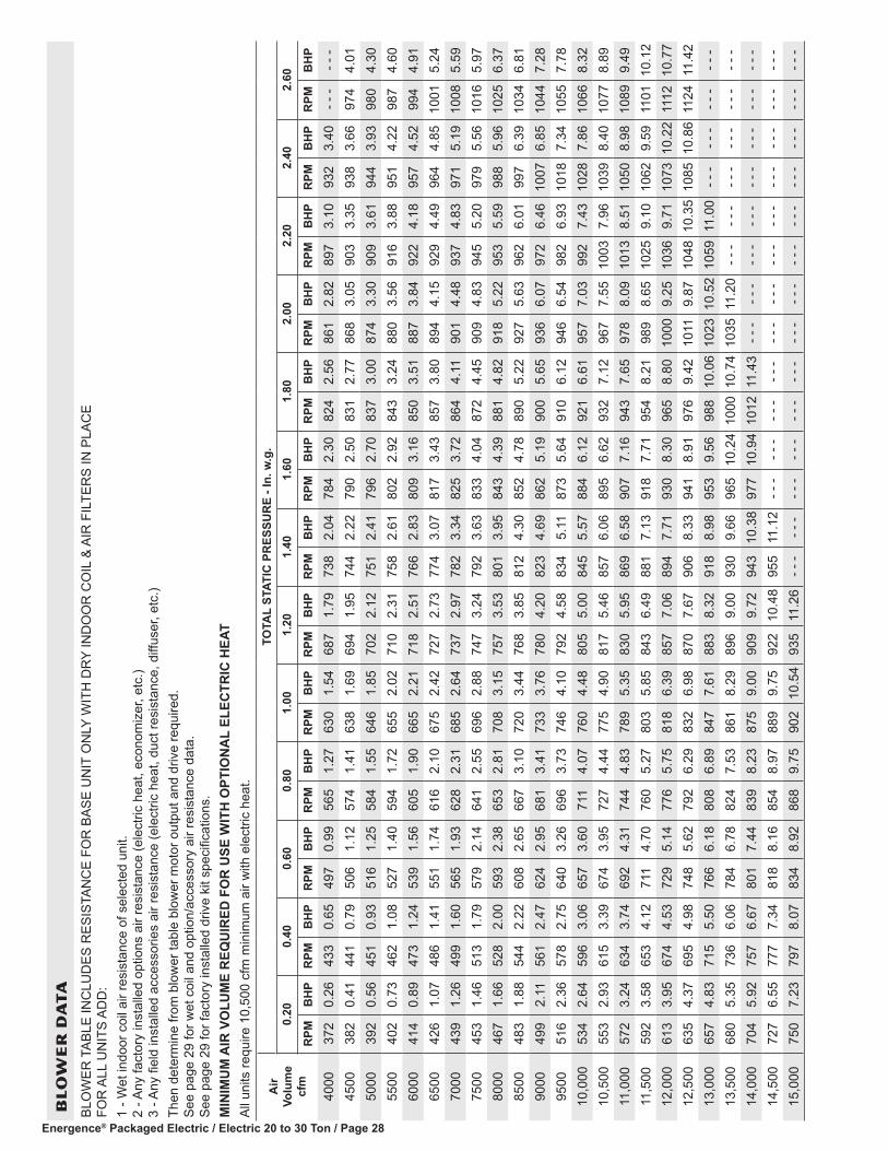
Energence® Packaged Electric / Electric 20 to 30 Ton / Page 28
BL
OW
ER
DA
TA
BLO
WER
TAB
LE IN
CLU
DES
RES
ISTA
NC
E FO
R B
ASE
UN
IT O
NLY
WIT
H D
RY
IND
OO
R C
OIL
& A
IR F
ILTE
RS
IN P
LAC
E FO
R A
LL U
NIT
S AD
D:
1 - W
et in
door
coi
l air
resi
stan
ce o
f sel
ecte
d un
it.
2 - A
ny fa
ctor
y in
stal
led
optio
ns a
ir re
sist
ance
(ele
ctric
hea
t, ec
onom
izer
, etc
.) 3
- Any
fiel
d in
stal
led
acce
ssor
ies
air r
esis
tanc
e (e
lect
ric h
eat,
duct
resi
stan
ce, d
iffus
er, e
tc.)
Then
det
erm
ine
from
blo
wer
tabl
e bl
ower
mot
or o
utpu
t and
driv
e re
quire
d.
See
page
29
for w
et c
oil a
nd o
ptio
n/ac
cess
ory
air r
esis
tanc
e da
ta.
See
page
29
for f
acto
ry in
stal
led
driv
e ki
t spe
cific
atio
ns.
MIN
IMU
M A
IR V
OLU
ME
REQ
UIR
ED F
OR
USE
WIT
H O
PTIO
NA
L EL
ECTR
IC H
EAT
All u
nits
requ
ire 1
0,50
0 cf
m m
inim
um a
ir w
ith e
lect
ric h
eat.
Air
Volu
me
cfm
TOTA
L ST
ATIC
PR
ESSU
RE
- In.
w.g
.0.
200.
400.
600.
801.
001.
201.
401.
601.
802.
002.
202.
402.
60
RPM
BH
PR
PMB
HP
RPM
BH
PR
PMB
HP
RPM
BH
PR
PMB
HP
RPM
BH
PR
PMB
HP
RPM
BH
PR
PMB
HP
RPM
BH
PR
PMB
HP
RPM
BH
P
4000
372
0.26
433
0.65
497
0.99
565
1.27
630
1.54
687
1.79
738
2.04
784
2.30
824
2.56
861
2.82
897
3.10
932
3.40
- - -
- - -
4500
382
0.41
441
0.79
506
1.12
574
1.41
638
1.69
694
1.95
744
2.22
790
2.50
831
2.77
868
3.05
903
3.35
938
3.66
974
4.01
5000
392
0.56
451
0.93
516
1.25
584
1.55
646
1.85
702
2.12
751
2.41
796
2.70
837
3.00
874
3.30
909
3.61
944
3.93
980
4.30
5500
402
0.73
462
1.08
527
1.40
594
1.72
655
2.02
710
2.31
758
2.61
802
2.92
843
3.24
880
3.56
916
3.88
951
4.22
987
4.60
6000
414
0.89
473
1.24
539
1.56
605
1.90
665
2.21
718
2.51
766
2.83
809
3.16
850
3.51
887
3.84
922
4.18
957
4.52
994
4.91
6500
426
1.07
486
1.41
551
1.74
616
2.10
675
2.42
727
2.73
774
3.07
817
3.43
857
3.80
894
4.15
929
4.49
964
4.85
1001
5.24
7000
439
1.26
499
1.60
565
1.93
628
2.31
685
2.64
737
2.97
782
3.34
825
3.72
864
4.11
901
4.48
937
4.83
971
5.19
1008
5.59
7500
453
1.46
513
1.79
579
2.14
641
2.55
696
2.88
747
3.24
792
3.63
833
4.04
872
4.45
909
4.83
945
5.20
979
5.56
1016
5.97
8000
467
1.66
528
2.00
593
2.38
653
2.81
708
3.15
757
3.53
801
3.95
843
4.39
881
4.82
918
5.22
953
5.59
988
5.96
1025
6.37
8500
483
1.88
544
2.22
608
2.65
667
3.10
720
3.44
768
3.85
812
4.30
852
4.78
890
5.22
927
5.63
962
6.01
997
6.39
1034
6.81
9000
499
2.11
561
2.47
624
2.95
681
3.41
733
3.76
780
4.20
823
4.69
862
5.19
900
5.65
936
6.07
972
6.46
1007
6.85
1044
7.28
9500
516
2.36
578
2.75
640
3.26
696
3.73
746
4.10
792
4.58
834
5.11
873
5.64
910
6.12
946
6.54
982
6.93
1018
7.34
1055
7.78
10,0
0053
42.
6459
63.
0665
73.
6071
14.
0776
04.
4880
55.
0084
55.
5788
46.
1292
16.
6195
77.
0399
27.
4310
287.
8610
668.
3210
,500
553
2.93
615
3.39
674
3.95
727
4.44
775
4.90
817
5.46
857
6.06
895
6.62
932
7.12
967
7.55
1003
7.96
1039
8.40
1077
8.89
11,0
0057
23.
2463
43.
7469
24.
3174
44.
8378
95.
3583
05.
9586
96.
5890
77.
1694
37.
6597
88.
0910
138.
5110
508.
9810
899.
4911
,500
592
3.58
653
4.12
711
4.70
760
5.27
803
5.85
843
6.49
881
7.13
918
7.71
954
8.21
989
8.65
1025
9.10
1062
9.59
1101
10.1
212
,000
613
3.95
674
4.53
729
5.14
776
5.75
818
6.39
857
7.06
894
7.71
930
8.30
965
8.80
1000
9.25
1036
9.71
1073
10.2
211
1210
.77
12,5
0063
54.
3769
54.
9874
85.
6279
26.
2983
26.
9887
07.
6790
68.
3394
18.
9197
69.
4210
119.
8710
4810
.35
1085
10.8
611
2411
.42
13,0
0065
74.
8371
55.
5076
66.
1880
86.
8984
77.
6188
38.
3291
88.
9895
39.
5698
810
.06
1023
10.5
210
5911
.00
- - -
- - -
- - -
- - -
13,5
0068
05.
3573
66.
0678
46.
7882
47.
5386
18.
2989
69.
0093
09.
6696
510
.24
1000
10.7
410
3511
.20
- - -
- - -
- - -
- - -
- - -
- - -
14,0
0070
45.
9275
76.
6780
17.
4483
98.
2387
59.
0090
99.
7294
310
.38
977
10.9
410
1211
.43
- - -
- - -
- - -
- - -
- - -
- - -
- - -
- - -
14,5
0072
76.
5577
77.
3481
88.
1685
48.
9788
99.
7592
210
.48
955
11.1
2- -
-- -
-- -
-- -
-- -
-- -
-- -
-- -
-- -
-- -
-- -
-- -
-15
,000
750
7.23
797
8.07
834
8.92
868
9.75
902
10.5
493
511
.26
- - -
- - -
- - -
- - -
- - -
- - -
- - -
- - -
- - -
- - -
- - -
- - -
- - -
- - -

Energence® Packaged Electric / Electric 20 to 30 Ton / Page 29
BLOWER DATADRIVE KIT SPECIFICATIONS
Motor Efficiency Nominal hp
Maximum hp
Drive Kit Number RPM Range
Standard 5 5.75 5 660 - 810
Standard 5 5.75 6 770 - 965
Standard 5 5.75 7 570 - 720
Standard 5 5.75 8 480 - 630
Standard 5 5.75 9 410 - 535
Standard 7.5 8.63 3 715 - 880
Standard 7.5 8.63 4 770 - 965
Standard 10 11.50 1 740 - 895
Standard 10 11.50 2 870 - 1045NOTESUsing total air volume and system static pressure requirements determine from blower performance tables rpm and motor output required. Maximum usable output of motors furnished are shown. In Canada, nominal motor output is also maximum usable motor output. If motors of comparable output are used, be sure to keep within the service factor limitations outlined on the motor nameplate.For VFD applications, nominal motor output is also maximum usable motor output.
FACTORY INSTALLED OPTIONS/FIELD INSTALLED ACCESSORY AIR RESISTANCE
Air Volume
cfm
Wet Indoor Coil Electric Heat Economizer
Filters Horizontal Roof CurbMERV 8 MERV 13
in. w.g. in. w.g. in. w.g. in. w.g. in. w.g. in. w.g.4000 0.04 0.01 0.00 0.00 0.00 0.04
4500 0.04 0.01 0.00 0.00 0.00 0.05
5000 0.05 0.01 0.00 0.00 0.00 0.06
5500 0.06 0.02 0.01 0.00 0.01 0.07
6000 0.07 0.02 0.01 0.00 0.02 0.08
6500 0.08 0.02 0.01 0.01 0.02 0.09
7000 0.09 0.03 0.02 0.01 0.03 0.10
7500 0.10 0.03 0.02 0.01 0.04 0.11
8000 0.11 0.03 0.02 0.01 0.04 0.13
8500 0.12 0.04 0.03 0.01 0.04 0.15
9000 0.13 0.04 0.04 0.01 0.04 0.17
9500 0.14 0.05 0.04 0.02 0.06 0.19
10,000 0.15 0.05 0.05 0.02 0.06 0.21
10,500 0.16 0.06 0.06 0.02 0.06 0.24
11,000 0.18 0.06 0.07 0.02 0.07 0.27
11,500 0.19 0.07 0.08 0.02 0.08 0.30
12,000 0.20 0.07 0.10 0.02 0.08 0.33
12,500 0.21 0.08 0.11 0.03 0.10 0.37
13,000 0.23 0.08 0.13 0.03 0.10 0.40
13,500 0.24 0.09 0.14 0.03 0.11 0.44
14,000 0.26 0.10 0.16 0.03 0.12 0.49
14,500 0.27 0.10 0.18 0.04 0.13 0.53
15,000 0.29 0.11 0.21 0.04 0.13 0.58

Energence® Packaged Electric / Electric 20 to 30 Ton / Page 30
BLOWER DATA
POWER EXHAUST PERFORMANCE - STANDARD STATICReturn Duct Negative Static Pressure Air Volume Exhausted
in. w.g. cfm 0.00 12,8000.05 12,2000.10 11,5000.15 10,8000.20 99000.25 90000.30 79000.35 67500.40 54500.45 41500.50 2900
POWER EXHAUST - 50% HIGH STATIC OPERATION
Air Volume
cfm
RETURN DUCT NEGATIVE STATIC PRESSURE - In. w.g.0 0.10 0.20 0.30 0.40 0.50 0.60 0.70 0.80 0.90 1.0
RPM BHP RPM BHP RPM BHP RPM BHP RPM BHP RPM BHP RPM BHP RPM BHP RPM BHP RPM BHP RPM BHP4000 - - - - - - - - - - - - 430 0.40 475 0.45 520 0.50 570 0.55 615 0.65 665 0.70 710 0.75 755 0.85 - - - - - -
4500 - - - - - - 415 0.45 460 0.55 500 0.60 545 0.65 585 0.70 625 0.80 670 0.85 710 0.95 750 1.00 795 1.105000 415 0.55 455 0.65 490 0.70 530 0.75 570 0.85 605 0.90 645 1.00 680 1.05 720 1.15 755 1.20 795 1.305500 460 0.75 495 0.85 525 0.90 560 0.95 595 1.05 630 1.10 665 1.20 700 1.30 735 1.35 765 1.45 800 1.556000 500 1.00 530 1.05 565 1.15 595 1.20 625 1.30 660 1.40 690 1.45 720 1.55 750 1.65 785 1.70 815 1.806500 540 1.25 570 1.30 600 1.40 630 1.50 660 1.60 685 1.65 715 1.75 745 1.85 775 1.95 805 2.05 830 2.107000 585 1.55 610 1.65 635 1.70 665 1.85 690 1.90 720 2.00 745 2.10 770 2.20 800 2.30 825 2.40 855 2.507500 625 1.90 650 2.00 675 2.10 700 2.20 725 2.30 750 2.40 775 2.50 800 2.60 825 2.70 850 2.80 875 2.908000 665 2.30 690 2.40 715 2.55 735 2.60 760 2.70 785 2.85 810 2.95 830 3.05 855 3.15 880 3.25 905 3.408500 710 2.80 730 2.90 755 3.00 775 3.10 795 3.20 820 3.35 840 3.45 865 3.55 885 3.65 910 3.80 930 3.90
POWER EXHAUST - 100% HIGH STATIC OPERATION
Air Volume
cfm
RETURN DUCT NEGATIVE STATIC PRESSURE - In. w.g.0 0.10 0.20 0.30 0.40 0.50 0.60 0.70 0.80 0.90 1.0
RPM BHP RPM BHP RPM BHP RPM BHP RPM BHP RPM BHP RPM BHP RPM BHP RPM BHP RPM BHP RPM BHP8500 475 1.30 500 1.30 525 1.40 550 1.50 585 1.60 625 1.75 670 1.90 710 2.10 745 2.30 780 2.50 815 2.70
9000 520 1.55 535 1.60 550 1.65 570 1.70 605 1.85 640 1.95 685 2.15 720 2.35 760 2.55 790 2.75 825 3.009500 550 1.80 560 1.85 575 1.90 600 2.00 620 2.10 655 2.20 695 2.40 735 2.60 770 2.80 800 3.00 835 3.25
10,000 575 2.10 590 2.15 605 2.20 620 2.30 645 2.40 675 2.50 710 2.65 745 2.85 780 3.05 815 3.30 845 3.5010,500 605 2.45 615 2.45 625 2.50 645 2.60 670 2.75 690 2.80 725 3.00 755 3.15 790 3.35 825 3.60 855 3.8011,000 630 2.80 645 2.85 660 2.95 675 3.00 685 3.05 715 3.20 740 3.30 770 3.50 805 3.70 835 3.90 870 4.2011,500 665 3.25 675 3.30 680 3.30 695 3.40 715 3.50 735 3.60 755 3.70 785 3.85 815 4.05 850 4.30 880 4.5012,000 685 3.60 700 3.70 710 3.75 725 3.85 740 3.95 755 4.00 780 4.15 805 4.30 830 4.45 860 4.65 890 4.9012,500 720 4.10 730 4.20 740 4.25 750 4.30 765 4.40 780 4.50 800 4.60 820 4.75 845 4.90 875 5.10 905 5.3513,000 745 4.60 750 4.65 765 4.75 780 4.85 790 4.90 805 5.00 820 5.10 840 5.25 865 5.40 890 5.60 915 5.8013,500 775 5.15 785 5.25 795 5.35 805 5.40 815 5.50 830 5.60 845 5.70 865 5.80 880 5.95 905 6.10 930 6.3014,000 805 5.80 810 5.80 820 5.90 830 6.00 845 6.10 855 6.20 870 6.30 885 6.40 905 6.55 925 6.70 - - - - - -
HIGH STATIC POWER EXHAUST WITH CONSTANT AIR VOLUME − DRIVE KIT SPECIFICATIONSPower Exhaust Model No. Motor HP Drive Kit Number RPM Range
LAPEB30/36A (50%) (2) 2 hp 1 406 - 533 LAPEB30/36B (50%) (2) 2 hp 2 531 - 731 LAPEB30/36C (50%) (2) 2 hp 3 731 - 932 LAPEB30/36D (100%) (3) 2 hp 1 406 - 533 LAPEB30/36E (100%) (3) 2 hp 2 531 - 731 LAPEB30/36F (100%) (3) 2 hp 3 731 - 932 NOTE − Using total air volume and system static pressure requirements, determine from blower performance tables rpm and motor output required.

Energence® Packaged Electric / Electric 20 to 30 Ton / Page 31
BLOWER DATA
CEILING DIFFUSER AIR RESISTANCE - in. w.g.
Air Volume
cfm
Step-Down Diffuser Flush Diffuser
LARTD30/36SLAFD30/36S
2 Ends Open 1 Side/2 Ends Open All Ends & Sides Open
7500 0.37 0.31 0.25 0.29
8000 0.42 0.36 0.29 0.34
8500 0.48 0.41 0.34 0.39
9000 0.55 0.47 0.39 0.44
9500 0.62 0.53 0.45 0.51
10,000 0.70 0.60 0.51 0.57
10,500 0.78 0.68 0.58 0.65
11,000 0.87 0.76 0.65 0.72
11,500 0.97 0.85 0.73 0.81
12,000 1.08 0.94 0.82 0.9
12,500 1.19 1.04 0.91 0.99
13,000 1.30 1.15 1.00 1.10
13,500 1.43 1.26 1.10 1.20
14,000 1.56 1.38 1.20 1.31
14,500 1.69 1.50 1.31 1.43
15,000 1.84 1.63 1.43 1.56
CEILING DIFFUSER AIR THROW DATA - ft.
Air Volume cfm
1 Effective Throw Range - ft.
Step-Down Flush
9000 40 - 47 29 - 35
9500 43 - 50 33 - 41
10,000 46 - 54 37 - 46
10,500 50 - 58 42 - 51
11,000 53 - 61 46 - 56
11,500 55 - 64 50 - 61
12,000 58 - 67 54 - 66
12,500 61 - 71 58 - 71
13,000 64 - 74 62 - 75
13,500 67 - 77 66 - 79 1 Throw is the horizontal or vertical distance an airstream travels on leaving the outletor diffuser before the maximum velocity is reduced
to 50 ft. per minute. Four sides open.

Energence® Packaged Electric / Electric 20 to 30 Ton / Page 32
ELECTRICAL DATA 20 TON20 TON HIGH EFFICIENCY - VARIABLE AIR VOLUME (VAV) LCH242H4V1 Voltage - 60hz 208/230V - 3 Ph 460V - 3 Ph 575V - 3 PhCompressor 1 Rated Load Amps 13.5 8 5
Locked Rotor Amps 109 59 40Compressor 2 Rated Load Amps 13.5 8 5
Locked Rotor Amps 109 59 40Compressor 3 Rated Load Amps 13.5 8 5
Locked Rotor Amps 109 59 40Compressor 4 Rated Load Amps 13.5 8 5
Locked Rotor Amps 109 59 40Outdoor Fan Motors (6)
Full Load Amps(total)
2.4(14.4)
1.3(7.8)
1(6)
Standard Power Exhaust (3) 0.33 HP
Full Load Amps(total)
2.4(7.2)
1.3(3.9)
1(3)
50% High Static Power Exhaust (2) 2 HP
Full Load Amps(total)
7.5(15)
3.4(6.8)
2.7(5.4)
100% High Static Power Exhaust (3) 2 HP
Full Load Amps(total)
7.5(22.5)
3.4(10.2)
2.7(8.1)
Service Outlet 115V GFI (amps) 15 15 20Indoor Blower Motor
Horsepower 5 7.5 10 5 7.5 10 5 7.5 10Full Load Amps 16.7 24.2 30.8 7.6 11 14 6.1 9 11
2 Maximum Overcurrent Protection
Unit Only 100 110 125 50 60 70 35 45 50With (3) 0.33 HP
Standard Power Exhaust110 125 125 60 60 70 40 45 50
With 50% High Static Power Exhaust (2) 2 HP
110 125 150 60 70 70 45 50 50
With 100% High Static Power Exhaust (3) 2 HP
125 125 150 60 70 80 45 50 50
3 Minimum Circuit Ampacity
Unit Only 90 99 107 50 54 58 34 38 40With (3) 0.33 HP
Standard Power Exhaust97 106 115 54 58 62 37 41 43
With 50% High Static Power Exhaust (2) 2 HP
105 114 122 57 61 65 40 43 46
With 100% High Static Power Exhaust (3) 2 HP
112 122 130 60 64 68 42 46 48
NOTE - All units have a minimum Short Circuit Current Rating (SCCR) of 5000 amps.1 Extremes of operating range are plus and minus 10% of line voltage.2 HACR type breaker or fuse.3 Refer to National or Canadian Electrical Code manual to determine wire, fuse and disconnect size requirements.

Energence® Packaged Electric / Electric 20 to 30 Ton / Page 33
ELECTRIC HEAT DATA 20 TON
20 TON HIGH EFFICIENCY - VARIABLE AIR VOLUME (VAV) LCH242H4V1 Voltage - 60hz - 3 phase 208/230V - 3 Ph 460V - 3 Ph 575V - 3 PhIndoor Blower Motor Horsepower 5 7.5 10 5 7.5 10 5 7.5 10
Electric Heat Voltage 208V 240V 208V 240V 208V 240V 480V 480V 480V 600V 600V 600V2 Maximum Overcurrent Protection
Unit+ Electric Heat
30 kW 4 100 125 4 110 125 4 125 150 60 60 70 45 50 5045 kW 4 150 175 4 150 175 175 175 80 90 90 70 70 7060 kW 4 150 175 175 175 4 175 200 90 90 90 70 70 8090 kW 4 225 250 4 225 250 4 250 4 300 125 125 150 100 100 110
120 kW 4 300 4 350 4 300 4 350 4 300 4 350 175 175 175 125 150 150Unit+
Electric Heat and Standard
Power Exhaust (3) 0.33 HP
30 kW 4 110 125 4 125 150 150 150 60 70 70 50 60 6045 kW 4 150 175 175 175 4 175 200 90 90 100 70 70 8060 kW 175 175 4 175 200 4 175 200 90 100 100 70 80 8090 kW 4 225 250 4 250 4 300 4 250 4 300 125 150 150 100 110 110
120 kW 4 300 4 350 4 300 4 350 4 300 4 350 175 175 175 150 150 150Unit+
Electric Heat and 50% High
Static Power Exhaust (2) 2 HP
30 kW 4 125 150 150 150 150 150 70 70 80 60 60 6045 kW 175 175 4 175 200 4 175 200 90 90 100 70 80 8060 kW 4 175 200 4 175 200 4 200 225 100 100 100 80 80 8090 kW 4 250 4 300 4 250 4 300 4 250 4 300 150 150 150 110 110 110
120 kW 4 300 4 350 4 300 4 350 350 4 350 175 175 175 150 150 150Unit+
Electric Heat and 100% High
Static Power Exhaust
(3) 2 HP
30 kW 150 150 150 150 4 150 175 70 80 80 60 60 6045 kW 4 175 200 200 200 4 200 225 90 100 100 80 80 8060 kW 4 175 200 4 200 225 4 200 225 100 100 110 80 80 9090 kW 4 250 4 300 4 250 4 300 300 4 300 150 150 150 110 110 125
120 kW 4 300 4 350 350 4 350 4 350 4 400 175 175 175 150 150 1503 Minimum Circuit Ampacity
Unit+ Electric Heat
30 kW 100 112 109 121 117 129 55 59 63 44 48 5045 kW 139 157 148 166 156 174 78 82 86 62 66 6860 kW 146 166 156 175 164 183 82 86 90 66 69 7290 kW 209 238 218 247 227 256 118 123 126 95 98 101
120 kW 272 310 281 319 289 328 154 159 162 124 127 130Unit+
Electric Heat and Standard
Power Exhaust (3) 0.33 HP
30 kW 109 121 118 130 126 138 60 64 68 48 52 5445 kW 148 166 157 175 165 183 83 87 91 66 70 7260 kW 155 175 165 184 173 192 87 91 95 70 73 7690 kW 218 247 227 256 236 265 123 127 131 98 102 105
120 kW 281 319 290 328 298 337 159 163 167 127 131 133Unit+
Electric Heat and 50% High
Static Power Exhaust (2) 2 HP
30 kW 118 130 128 140 136 148 64 68 72 51 55 5745 kW 157 175 167 185 175 193 86 90 94 69 73 7560 kW 165 184 175 194 183 202 91 95 99 73 76 7990 kW 228 257 237 266 245 274 127 131 135 101 105 108
120 kW 290 329 300 338 308 346 163 167 171 130 134 136Unit+
Electric Heat and 100% High
Static Power Exhaust
(3) 2 HP
30 kW 128 140 137 149 145 157 68 72 76 54 58 6045 kW 167 185 176 194 184 202 90 95 98 72 76 7960 kW 175 194 184 203 192 211 95 99 103 76 80 8290 kW 237 266 247 275 255 284 131 135 139 105 108 111
120 kW 300 338 309 348 317 356 167 171 175 134 137 1401 Extremes of operating range are plus and minus 10% of line voltage. 2 HACR type breaker or fuse.3 Refer to National or Canadian Electrical Code manual to determine wire, fuse and disconnect size requirements.4 Factory installed circuit breaker not available.

Energence® Packaged Electric / Electric 20 to 30 Ton / Page 34
ELECTRICAL DATA 25 TON25 TON HIGH EFFICIENCY - CONSTANT AIR VOLUME (CAV) LCH300H4B1 Voltage - 60hz 208/230V - 3 Ph 460V - 3 Ph 575V - 3 PhCompressor 1 Rated Load Amps 22.4 10.6 7.7
Locked Rotor Amps 149 75 54Compressor 2 Rated Load Amps 22.4 10.6 7.7
Locked Rotor Amps 149 75 54Compressor 3 Rated Load Amps 22.4 10.6 7.7
Locked Rotor Amps 149 75 54Compressor 4 Rated Load Amps 22.4 10.6 7.7
Locked Rotor Amps 149 75 54Outdoor Fan Motors (6)
Full Load Amps(total)
2.4(14.4)
1.3(7.8)
1(6)
Standard Power Exhaust (3) 0.33 HP
Full Load Amps(total)
2.4(7.2)
1.3(3.9)
1(3)
50% High Static Power Exhaust (2) 2 HP
Full Load Amps(total)
7.5(15)
3.4(6.8)
2.7(5.4)
100% High Static Power Exhaust (3) 2 HP
Full Load Amps(total)
7.5(22.5)
3.4(10.2)
2.7(8.1)
Service Outlet 115V GFI (amps) 15 15 20Indoor Blower Motor
Horsepower 5 7.5 10 5 7.5 10 5 7.5 10Full Load Amps 16.7 24.2 30.8 7.6 11 14 6.1 9 11
2 Maximum Overcurrent Protection
Unit Only 150 150 150 70 70 80 50 50 60With (3) 0.33 HP
Standard Power Exhaust150 150 150 70 70 80 60 60 60
With 50% High Static Power Exhaust (2) 2 HP
150 150 175 70 80 80 60 60 60
With 100% High Static Power Exhaust (3) 2 HP
150 175 175 80 80 90 60 60 60
3 Minimum Circuit Ampacity
Unit Only 127 135 143 61 64 68 45 49 51With (3) 0.33 HP
Standard Power Exhaust128 134 142 62 65 68 46 48 52
With 50% High Static Power Exhaust (2) 2 HP
142 150 158 68 71 75 51 54 56
With 100% High Static Power Exhaust (3) 2 HP
149 157 165 71 75 78 53 57 59
NOTE - All units have a minimum Short Circuit Current Rating (SCCR) of 5000 amps.1 Extremes of operating range are plus and minus 10% of line voltage.2 HACR type breaker or fuse.3 Refer to National or Canadian Electrical Code manual to determine wire, fuse and disconnect size requirements.

Energence® Packaged Electric / Electric 20 to 30 Ton / Page 35
ELECTRIC HEAT DATA 25 TON
25 TON HIGH EFFICIENCY - CONSTANT AIR VOLUME (CAV) LCH300H4B1 Voltage - 60hz - 3 phase 208/230V - 3 Ph 460V - 3 Ph 575V - 3 PhIndoor Blower Motor Horsepower 5 7.5 10 5 7.5 10 5 7.5 10
Electric Heat Voltage 208V 240V 208V 240V 208V 240V 480V 480V 480V 600V 600V 600V2 Maximum Overcurrent Protection
Unit+ Electric Heat
30 kW 150 150 150 150 150 150 70 70 80 50 50 6045 kW 4 150 175 4 150 175 175 175 80 90 90 70 70 7060 kW 4 150 175 175 175 4 175 200 90 90 90 70 70 8090 kW 4 225 250 4 225 250 4 250 4 300 125 125 150 100 100 110
120 kW 4 300 4 350 4 300 4 350 4 300 4 350 175 175 175 125 150 150Unit+
Electric Heat and Standard
Power Exhaust (3) 0.33 HP
30 kW 150 150 150 150 150 150 70 70 70 50 50 6045 kW 4 150 175 4 150 175 175 175 80 90 90 70 70 7060 kW 4 150 175 175 175 4 175 200 90 90 100 70 70 8090 kW 4 225 250 4 225 250 4 250 4 300 125 125 150 100 100 110
120 kW 4 300 4 350 4 300 4 350 4 300 4 350 175 175 175 125 150 150Unit+
Electric Heat and 50% High
Static Power Exhaust (2) 2 HP
30 kW 150 150 150 150 175 175 70 80 80 60 60 6045 kW 175 175 4 175 200 4 175 200 90 90 100 70 80 8060 kW 4 175 200 4 175 200 4 200 225 100 100 100 80 80 8090 kW 4 250 4 300 4 250 4 300 4 250 4 300 150 150 150 110 110 110
120 kW 4 300 4 350 4 300 4 350 350 4 350 175 175 175 150 150 150Unit+
Electric Heat and 100% High
Static Power Exhaust
(3) 2 HP
30 kW 150 150 175 175 175 175 80 80 90 60 60 6045 kW 4 175 200 200 200 4 200 225 90 100 100 80 80 8060 kW 4 175 200 4 200 225 4 200 225 100 100 110 80 80 9090 kW 4 250 4 300 4 250 4 300 300 4 300 150 150 150 110 110 125
120 kW 4 300 4 350 350 4 350 4 350 4 400 175 175 175 150 150 1503 Minimum Circuit Ampacity
Unit+ Electric Heat
30 kW 127 127 135 135 143 143 61 64 68 45 49 5145 kW 139 157 148 166 156 174 78 82 86 62 66 6860 kW 146 166 156 175 164 183 82 86 90 66 69 7290 kW 209 238 218 247 227 256 118 123 126 95 98 101
120 kW 272 310 281 319 289 328 154 159 162 124 127 130Unit+
Electric Heat and Standard
Power Exhaust (3) 0.33 HP
30 kW 128 128 134 134 142 142 62 65 68 46 48 5245 kW 140 158 148 166 157 175 79 83 87 63 66 7060 kW 148 167 155 175 165 184 84 87 91 67 70 7390 kW 210 239 218 247 227 256 120 123 127 96 98 102
120 kW 273 311 281 319 290 328 156 159 163 125 127 131Unit+
Electric Heat and 50% High
Static Power Exhaust (2) 2 HP
30 kW 142 142 150 150 158 158 68 71 75 51 55 5745 kW 157 175 167 185 175 193 86 90 94 69 73 7560 kW 165 184 175 194 183 202 91 95 99 73 76 7990 kW 228 257 237 266 245 274 127 131 135 101 105 108
120 kW 290 329 300 338 308 346 163 167 171 130 134 136Unit+
Electric Heat and 100% High
Static Power Exhaust
(3) 2 HP
30 kW 149 149 157 157 165 165 71 75 78 54 58 6045 kW 167 185 176 194 184 202 90 95 98 72 76 7960 kW 175 194 184 203 192 211 95 99 103 76 80 8290 kW 237 266 247 275 255 284 131 135 139 105 108 111
120 kW 300 338 309 348 317 356 167 171 175 134 137 1401 Extremes of operating range are plus and minus 10% of line voltage. 2 HACR type breaker or fuse.3 Refer to National or Canadian Electrical Code manual to determine wire, fuse and disconnect size requirements.4 Factory installed circuit breaker not available.

Energence® Packaged Electric / Electric 20 to 30 Ton / Page 36
ELECTRICAL DATA 25 TON25 TON HIGH EFFICIENCY - VARIABLE AND MULTI-STAGE AIR VOLUME LCH300H4V,M1 Voltage - 60hz 208/230V - 3 Ph 460V - 3 Ph 575V - 3 PhCompressor 1 Rated Load Amps 22.4 10.6 7.7
Locked Rotor Amps 149 75 54Compressor 2 Rated Load Amps 22.4 10.6 7.7
Locked Rotor Amps 149 75 54Compressor 3 Rated Load Amps 22.4 10.6 7.7
Locked Rotor Amps 149 75 54Compressor 4 Rated Load Amps 22.4 10.6 7.7
Locked Rotor Amps 149 75 54Outdoor Fan Motors (6)
Full Load Amps(total)
2.4(14.4)
1.3(7.8)
1(6)
Standard Power Exhaust (3) 0.33 HP
Full Load Amps(total)
2.4(7.2)
1.3(3.9)
1(3)
50% High Static Power Exhaust (2) 2 HP
Full Load Amps(total)
7.5(15)
3.4(6.8)
2.7(5.4)
100% High Static Power Exhaust (3) 2 HP
Full Load Amps(total)
7.5(22.5)
3.4(10.2)
2.7(8.1)
Service Outlet 115V GFI (amps) 15 15 20Indoor Blower Motor
Horsepower 5 7.5 10 5 7.5 10 5 7.5 10Full Load Amps 16.7 24.2 30.8 7.6 11 14 6.1 9 11
2 Maximum Overcurrent Protection
Unit Only 150 150 150 70 70 80 50 50 60With (3) 0.33 HP
Standard Power Exhaust150 150 175 70 70 80 50 60 60
With 50% High Static Power Exhaust (2) 2 HP
150 150 175 70 80 80 60 60 60
With 100% High Static Power Exhaust (3) 2 HP
150 175 175 80 80 90 60 60 60
3 Minimum Circuit Ampacity
Unit Only 127 135 143 61 64 68 45 49 51With (3) 0.33 HP
Standard Power Exhaust134 142 150 65 68 72 48 52 54
With 50% High Static Power Exhaust (2) 2 HP
142 150 158 68 71 75 51 54 56
With 100% High Static Power Exhaust (3) 2 HP
149 157 165 71 75 78 53 57 59
NOTE - All units have a minimum Short Circuit Current Rating (SCCR) of 5000 amps.1 Extremes of operating range are plus and minus 10% of line voltage.2 HACR type breaker or fuse.3 Refer to National or Canadian Electrical Code manual to determine wire, fuse and disconnect size requirements.

Energence® Packaged Electric / Electric 20 to 30 Ton / Page 37
ELECTRIC HEAT DATA 25 TON
25 TON HIGH EFFICIENCY - VARIABLE AND MULTI-STAGE AIR VOLUME LCH300H4V,M1 Voltage - 60hz - 3 phase 208/230V - 3 Ph 460V - 3 Ph 575V - 3 PhIndoor Blower Motor Horsepower 5 7.5 10 5 7.5 10 5 7.5 10
Electric Heat Voltage 208V 240V 208V 240V 208V 240V 480V 480V 480V 600V 600V 600V2 Maximum Overcurrent Protection
Unit+ Electric Heat
30 kW 150 150 150 150 150 150 70 70 80 50 50 6045 kW 4 150 175 4 150 175 175 175 80 90 90 70 70 7060 kW 4 150 175 175 175 4 175 200 90 90 90 70 70 8090 kW 4 225 250 4 225 250 4 250 4 300 125 125 150 100 100 110
120 kW 4 300 4 350 4 300 4 350 4 300 4 350 175 175 175 125 150 150Unit+
Electric Heat and Standard
Power Exhaust (3) 0.33 HP
30 kW 150 150 150 150 175 175 70 70 80 50 60 6045 kW 4 150 175 175 175 4 175 200 90 90 100 70 70 8060 kW 175 175 4 175 200 4 175 200 90 100 100 70 80 8090 kW 4 225 250 4 250 4 300 4 250 4 300 125 150 150 100 110 110
120 kW 4 300 4 350 4 300 4 350 4 300 4 350 175 175 175 150 150 150Unit+
Electric Heat and 50% High
Static Power Exhaust (2) 2 HP
30 kW 150 150 150 150 175 175 70 80 80 60 60 6045 kW 175 175 4 175 200 4 175 200 90 90 100 70 80 8060 kW 4 175 200 4 175 200 4 200 225 100 100 100 80 80 8090 kW 4 250 4 300 4 250 4 300 4 250 4 300 150 150 150 110 110 110
120 kW 4 300 4 350 4 300 4 350 350 4 350 175 175 175 150 150 150Unit+
Electric Heat and 100% High
Static Power Exhaust
(3) 2 HP
30 kW 150 150 175 175 175 175 80 80 90 60 60 6045 kW 4 175 200 200 200 4 200 225 90 100 100 80 80 8060 kW 4 175 200 4 200 225 4 200 225 100 100 110 80 80 9090 kW 4 250 4 300 4 250 4 300 300 4 300 150 150 150 110 110 125
120 kW 4 300 4 350 350 4 350 4 350 4 400 175 175 175 150 150 1503 Minimum Circuit Ampacity
Unit+ Electric Heat
30 kW 127 127 135 135 143 143 61 64 68 45 49 5145 kW 139 157 148 166 156 174 78 82 86 62 66 6860 kW 146 166 156 175 164 183 82 86 90 66 69 7290 kW 209 238 218 247 227 256 118 123 126 95 98 101
120 kW 272 310 281 319 289 328 154 159 162 124 127 130Unit+
Electric Heat and Standard
Power Exhaust (3) 0.33 HP
30 kW 134 134 142 142 150 150 65 68 72 48 52 5445 kW 148 166 157 175 165 183 83 87 91 66 70 7260 kW 155 175 165 184 173 192 87 91 95 70 73 7690 kW 218 247 227 256 236 265 123 127 131 98 102 105
120 kW 281 319 290 328 298 337 159 163 167 127 131 133Unit+
Electric Heat and 50% High
Static Power Exhaust (2) 2 HP
30 kW 142 142 150 150 158 158 68 71 75 51 55 5745 kW 157 175 167 185 175 193 86 90 94 69 73 7560 kW 165 184 175 194 183 202 91 95 99 73 76 7990 kW 228 257 237 266 245 274 127 131 135 101 105 108
120 kW 290 329 300 338 308 346 163 167 171 130 134 136Unit+
Electric Heat and 100% High
Static Power Exhaust
(3) 2 HP
30 kW 149 149 157 157 165 165 71 75 78 54 58 6045 kW 167 185 176 194 184 202 90 95 98 72 76 7960 kW 175 194 184 203 192 211 95 99 103 76 80 8290 kW 237 266 247 275 255 284 131 135 139 105 108 111
120 kW 300 338 309 348 317 356 167 171 175 134 137 1401 Extremes of operating range are plus and minus 10% of line voltage. 2 HACR type breaker or fuse.3 Refer to National or Canadian Electrical Code manual to determine wire, fuse and disconnect size requirements.4 Factory installed circuit breaker not available.
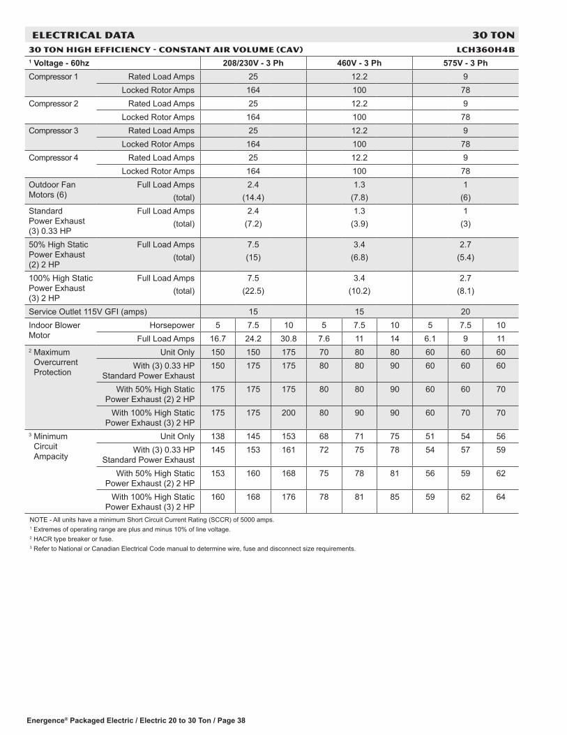
Energence® Packaged Electric / Electric 20 to 30 Ton / Page 38
ELECTRICAL DATA 30 TON30 TON HIGH EFFICIENCY - CONSTANT AIR VOLUME (CAV) LCH360H4B1 Voltage - 60hz 208/230V - 3 Ph 460V - 3 Ph 575V - 3 PhCompressor 1 Rated Load Amps 25 12.2 9
Locked Rotor Amps 164 100 78Compressor 2 Rated Load Amps 25 12.2 9
Locked Rotor Amps 164 100 78Compressor 3 Rated Load Amps 25 12.2 9
Locked Rotor Amps 164 100 78Compressor 4 Rated Load Amps 25 12.2 9
Locked Rotor Amps 164 100 78Outdoor Fan Motors (6)
Full Load Amps(total)
2.4(14.4)
1.3(7.8)
1(6)
Standard Power Exhaust (3) 0.33 HP
Full Load Amps(total)
2.4(7.2)
1.3(3.9)
1(3)
50% High Static Power Exhaust (2) 2 HP
Full Load Amps(total)
7.5(15)
3.4(6.8)
2.7(5.4)
100% High Static Power Exhaust (3) 2 HP
Full Load Amps(total)
7.5(22.5)
3.4(10.2)
2.7(8.1)
Service Outlet 115V GFI (amps) 15 15 20Indoor Blower Motor
Horsepower 5 7.5 10 5 7.5 10 5 7.5 10Full Load Amps 16.7 24.2 30.8 7.6 11 14 6.1 9 11
2 Maximum Overcurrent Protection
Unit Only 150 150 175 70 80 80 60 60 60With (3) 0.33 HP
Standard Power Exhaust150 175 175 80 80 90 60 60 60
With 50% High Static Power Exhaust (2) 2 HP
175 175 175 80 80 90 60 60 70
With 100% High Static Power Exhaust (3) 2 HP
175 175 200 80 90 90 60 70 70
3 Minimum Circuit Ampacity
Unit Only 138 145 153 68 71 75 51 54 56With (3) 0.33 HP
Standard Power Exhaust145 153 161 72 75 78 54 57 59
With 50% High Static Power Exhaust (2) 2 HP
153 160 168 75 78 81 56 59 62
With 100% High Static Power Exhaust (3) 2 HP
160 168 176 78 81 85 59 62 64
NOTE - All units have a minimum Short Circuit Current Rating (SCCR) of 5000 amps.1 Extremes of operating range are plus and minus 10% of line voltage.2 HACR type breaker or fuse.3 Refer to National or Canadian Electrical Code manual to determine wire, fuse and disconnect size requirements.

Energence® Packaged Electric / Electric 20 to 30 Ton / Page 39
ELECTRIC HEAT DATA 30 TON
30 TON HIGH EFFICIENCY - CONSTANT AIR VOLUME (CAV) LCH360H4B1 Voltage - 60hz - 3 phase 208/230V - 3 Ph 460V - 3 Ph 575V - 3 PhIndoor Blower Motor Horsepower 5 7.5 10 5 7.5 10 5 7.5 10
Electric Heat Voltage 208V 240V 208V 240V 208V 240V 480V 480V 480V 600V 600V 600V2 Maximum Overcurrent Protection
Unit+ Electric Heat
30 kW 150 150 150 150 175 175 70 80 80 60 60 6045 kW 4 150 175 4 150 175 175 175 80 90 90 70 70 7060 kW 4 150 175 175 175 4 175 200 90 90 90 70 70 8090 kW 4 225 250 4 225 250 4 250 4 300 125 125 150 100 100 110
120 kW 4 300 4 350 4 300 4 350 4 300 4 350 175 175 175 125 150 150Unit+
Electric Heat and Standard
Power Exhaust (3) 0.33 HP
30 kW 150 150 175 175 175 175 80 80 90 60 60 6045 kW 4 150 175 175 175 4 175 200 90 90 100 70 70 8060 kW 175 175 4 175 200 4 175 200 90 100 100 70 80 8090 kW 4 225 250 4 250 4 300 4 250 4 300 125 150 150 100 110 110
120 kW 4 300 4 350 4 300 4 350 4 300 4 350 175 175 175 150 150 150Unit+
Electric Heat and 50% High
Static Power Exhaust (2) 2 HP
30 kW 175 175 175 175 175 175 80 80 90 60 60 7045 kW 175 175 4 175 200 4 175 200 90 90 100 70 80 8060 kW 4 175 200 4 175 200 4 200 225 100 100 100 80 80 8090 kW 4 250 4 300 4 250 4 300 4 250 4 300 150 150 150 110 110 110
120 kW 4 300 4 350 4 300 4 350 350 4 350 175 175 175 150 150 150Unit+
Electric Heat and 100% High
Static Power Exhaust
(3) 2 HP
30 kW 175 175 175 175 200 200 80 90 90 60 70 7045 kW 4 175 200 200 200 4 200 225 90 100 100 80 80 8060 kW 4 175 200 4 200 225 4 200 225 100 100 110 80 80 9090 kW 4 250 4 300 4 250 4 300 300 4 300 150 150 150 110 110 125
120 kW 4 300 4 350 350 4 350 4 350 4 400 175 175 175 150 150 1503 Minimum Circuit Ampacity
Unit+ Electric Heat
30 kW 138 138 145 145 153 153 68 71 75 51 54 5645 kW 139 157 148 166 156 174 78 82 86 62 66 6860 kW 146 166 156 175 164 183 82 86 90 66 69 7290 kW 209 238 218 247 227 256 118 123 126 95 98 101
120 kW 272 310 281 319 289 328 154 159 162 124 127 130Unit+
Electric Heat and Standard
Power Exhaust (3) 0.33 HP
30 kW 145 145 153 153 161 161 72 75 78 54 57 5945 kW 148 166 157 175 165 183 83 87 91 66 70 7260 kW 155 175 165 184 173 192 87 91 95 70 73 7690 kW 218 247 227 256 236 265 123 127 131 98 102 105
120 kW 281 319 290 328 298 337 159 163 167 127 131 133Unit+
Electric Heat and 50% High
Static Power Exhaust (2) 2 HP
30 kW 153 153 160 160 168 168 75 78 81 56 59 6245 kW 157 175 167 185 175 193 86 90 94 69 73 7560 kW 165 184 175 194 183 202 91 95 99 73 76 7990 kW 228 257 237 266 245 274 127 131 135 101 105 108
120 kW 290 329 300 338 308 346 163 167 171 130 134 136Unit+
Electric Heat and 100% High
Static Power Exhaust
(3) 2 HP
30 kW 160 160 168 168 176 176 78 81 85 59 62 6445 kW 167 185 176 194 184 202 90 95 98 72 76 7960 kW 175 194 184 203 192 211 95 99 103 76 80 8290 kW 237 266 247 275 255 284 131 135 139 105 108 111
120 kW 300 338 309 348 317 356 167 171 175 134 137 1401 Extremes of operating range are plus and minus 10% of line voltage. 2 HACR type breaker or fuse.3 Refer to National or Canadian Electrical Code manual to determine wire, fuse and disconnect size requirements.4 Factory installed circuit breaker not available.

Energence® Packaged Electric / Electric 20 to 30 Ton / Page 40
ELECTRICAL DATA 30 TON30 TON HIGH EFFICIENCY - VARIABLE AND MULTI-STAGE AIR VOLUME LCH360H4V,M1 Voltage - 60hz 208/230V - 3 Ph 460V - 3 Ph 575V - 3 PhCompressor 1 Rated Load Amps 25 12.2 9
Locked Rotor Amps 164 100 78Compressor 2 Rated Load Amps 25 12.2 9
Locked Rotor Amps 164 100 78Compressor 3 Rated Load Amps 25 12.2 9
Locked Rotor Amps 164 100 78Compressor 4 Rated Load Amps 25 12.2 9
Locked Rotor Amps 164 100 78Outdoor Fan Motors (6)
Full Load Amps(total)
2.4(14.4)
1.3(7.8)
1(6)
Standard Power Exhaust (3) 0.33 HP
Full Load Amps(total)
2.4(7.2)
1.3(3.9)
1(3)
50% High Static Power Exhaust (2) 2 HP
7.5(15)
3.4(6.8)
2.7(5.4)
100% High Static Power Exhaust (3) 2 HP
7.5(22.5)
3.4(10.2)
2.7(8.1)
Service Outlet 115V GFI (amps) 15 15 20Indoor Blower Motor
Horsepower 5 7.5 10 5 7.5 10 5 7.5 10Full Load Amps 16.7 24.2 30.8 7.6 11 14 6.1 9 11
2 Maximum Overcurrent Protection
Unit Only 150 150 175 70 80 80 60 60 60With (3) 0.33 HP
Standard Power Exhaust150 175 175 80 80 90 60 60 60
With 50% High Static Power Exhaust (2) 2 HP
175 175 175 80 80 90 60 60 70
With 100% High Static Power Exhaust (3) 2 HP
175 175 200 80 90 90 60 70 70
3 Minimum Circuit Ampacity
Unit Only 138 145 153 68 71 75 51 54 56With (3) 0.33 HP
Standard Power Exhaust145 153 161 72 75 78 54 57 59
With 50% High Static Power Exhaust (2) 2 HP
153 160 168 75 78 81 56 59 62
With 100% High Static Power Exhaust (3) 2 HP
160 168 176 78 81 85 59 62 64
NOTE - All units have a minimum Short Circuit Current Rating (SCCR) of 5000 amps.1 Extremes of operating range are plus and minus 10% of line voltage.2 HACR type breaker or fuse.3 Refer to National or Canadian Electrical Code manual to determine wire, fuse and disconnect size requirements.

Energence® Packaged Electric / Electric 20 to 30 Ton / Page 41
ELECTRIC HEAT DATA 30 TON
30 TON HIGH EFFICIENCY - VARIABLE AND MULTI-STAGE AIR VOLUME LCH360H4V,M1 Voltage - 60hz - 3 phase 208/230V - 3 Ph 460V - 3 Ph 575V - 3 PhIndoor Blower Motor Horsepower 5 7.5 10 5 7.5 10 5 7.5 10
Electric Heat Voltage 208V 240V 208V 240V 208V 240V 480V 480V 480V 600V 600V 600V2 Maximum Overcurrent Protection
Unit+ Electric Heat
30 kW 150 150 150 150 175 175 70 80 80 60 60 6045 kW 4 150 175 4 150 175 175 175 80 90 90 70 70 7060 kW 4 150 175 175 175 4 175 200 90 90 90 70 70 8090 kW 4 225 250 4 225 250 4 250 4 300 125 125 150 100 100 110
120 kW 4 300 4 350 4 300 4 350 4 300 4 350 175 175 175 125 150 150Unit+
Electric Heat and Standard
Power Exhaust (3) 0.33 HP
30 kW 150 150 175 175 175 175 80 80 90 60 60 6045 kW 4 150 175 175 175 4 175 200 90 90 100 70 70 8060 kW 175 175 4 175 200 4 175 200 90 100 100 70 80 8090 kW 4 225 250 4 250 4 300 4 250 4 300 125 150 150 100 110 110
120 kW 4 300 4 350 4 300 4 350 4 300 4 350 175 175 175 150 150 150Unit+
Electric Heat and 50% High
Static Power Exhaust (2) 2 HP
30 kW 175 175 175 175 175 175 80 80 90 60 60 7045 kW 175 175 4 175 200 4 175 200 90 90 100 70 80 8060 kW 4 175 200 4 175 200 4 200 225 100 100 100 80 80 8090 kW 4 250 4 300 4 250 4 300 4 250 4 300 150 150 150 110 110 110
120 kW 4 300 4 350 4 300 4 350 350 4 350 175 175 175 150 150 150Unit+
Electric Heat and 100% High
Static Power Exhaust
(3) 2 HP
30 kW 175 175 175 175 200 200 80 90 90 60 70 7045 kW 4 175 200 200 200 4 200 225 90 100 100 80 80 8060 kW 4 175 200 4 200 225 4 200 225 100 100 110 80 80 9090 kW 4 250 4 300 4 250 4 300 300 4 300 150 150 150 110 110 125
120 kW 4 300 4 350 350 4 350 4 350 4 400 175 175 175 150 150 1503 Minimum Circuit Ampacity
Unit+ Electric Heat
30 kW 138 138 145 145 153 153 68 71 75 51 54 5645 kW 139 157 148 166 156 174 78 82 86 62 66 6860 kW 146 166 156 175 164 183 82 86 90 66 69 7290 kW 209 238 218 247 227 256 118 123 126 95 98 101
120 kW 272 310 281 319 289 328 154 159 162 124 127 130Unit+
Electric Heat and Standard
Power Exhaust (3) 0.33 HP
30 kW 145 145 153 153 161 161 72 75 78 54 57 5945 kW 148 166 157 175 165 183 83 87 91 66 70 7260 kW 155 175 165 184 173 192 87 91 95 70 73 7690 kW 218 247 227 256 236 265 123 127 131 98 102 105
120 kW 281 319 290 328 298 337 159 163 167 127 131 133Unit+
Electric Heat and 50% High
Static Power Exhaust (2) 2 HP
30 kW 153 153 160 160 168 168 75 78 81 56 59 6245 kW 157 175 167 185 175 193 86 90 94 69 73 7560 kW 165 184 175 194 183 202 91 95 99 73 76 7990 kW 228 257 237 266 245 274 127 131 135 101 105 108
120 kW 290 329 300 338 308 346 163 167 171 130 134 136Unit+
Electric Heat and 100% High
Static Power Exhaust
(3) 2 HP
30 kW 160 160 168 168 176 176 78 81 85 59 62 6445 kW 167 185 176 194 184 202 90 95 98 72 76 7960 kW 175 194 184 203 192 211 95 99 103 76 80 8290 kW 237 266 247 275 255 284 131 135 139 105 108 111
120 kW 300 338 309 348 317 356 167 171 175 134 137 1401 Extremes of operating range are plus and minus 10% of line voltage. 2 HACR type breaker or fuse.3 Refer to National or Canadian Electrical Code manual to determine wire, fuse and disconnect size requirements.4 Factory installed circuit breaker not available.

Energence® Packaged Electric / Electric 20 to 30 Ton / Page 42
ELECTRIC HEAT CAPACITIES
Volts Input
30 kW 45 kW 60 kW 90 kW 120 kWkW
Input Btuh
Output No. of Stages
kW Input
Btuh Output
No. of Stages
kW Input
Btuh Output
No. of Stages
kW Input
Btuh Output
No. of Stages
kW Input
Btuh Output
No. of Stages
208 22.5 76,800 1 33.8 115,300 2 45.0 153,600 2 67.6 230,700 2 90.2 307,800 2
220 25.2 86,000 1 37.8 129,000 2 50.4 172,000 2 75.6 258,000 2 100.8 344,000 2
230 27.5 93,900 1 41.3 141,000 2 55.1 188,000 2 82.7 282,200 2 110.2 376,100 2
240 30.0 102,400 1 45.0 153,600 2 60.0 204,800 2 90.0 307,100 2 120.0 409,500 2
440 25.2 86,000 1 37.8 129,000 2 50.4 172,000 2 75.6 258,000 2 100.8 344,000 2
460 27.5 93,900 1 41.3 141,000 2 55.1 188,000 2 82.7 282,200 2 110.2 376,100 2
480 30.0 102,400 1 45.0 153,600 2 60.0 204,800 2 90.0 307,100 2 120.0 409,500 2
550 25.2 86,000 1 37.8 129,000 2 50.4 172,000 2 75.6 258,000 2 100.8 344,000 2
575 27.5 93,900 1 41.3 141,000 2 55.1 188,000 2 82.7 282,200 2 110.2 376,100 2
600 30.0 102,400 1 45.0 153,600 2 60.0 204,800 2 90.0 307,100 2 120.0 409,500 2
ELECTRICAL ACCESSORIES
20 TON HIGH EFFICIENCY LCH242H4
Voltage - 60hz - 3 phase 208/230V 460V 575VIndoor Blower Motor Horsepower 5 7.5 10 5 7.5 10 5 7.5 10Disconnect Unit Only 54W86 54W86 54W86 54W85 54W85 54W85 54W85 54W85 54W85
Unit+ Electric Heat
and Standard Power Exhaust
(3) 0.33 HP
0 kW 54W86 54W86 54W86 54W85 54W85 54W85 54W85 54W85 54W8530 kW 54W86 54W86 54W86 54W85 54W85 54W85 54W85 54W85 54W8545 kW 54W87 54W87 54W87 54W85 54W85 54W86 54W85 54W85 54W8560 kW 54W87 54W87 54W87 54W86 54W86 54W86 54W85 54W86 54W8690 kW N/A N/A N/A 54W86 54W86 54W86 54W86 54W86 54W86
120 kW N/A N/A N/A 54W87 54W87 54W87 54W86 54W86 54W86
Unit+ Electric Heat
and 50% High Static Power
Exhaust (2) 2 HP
0 kW 54W86 54W86 54W87 54W85 54W85 54W85 54W85 54W85 54W8530 kW 54W86 54W86 54W87 54W85 54W85 54W85 54W85 54W85 54W8545 kW 54W87 54W87 54W87 54W85 54W86 54W86 54W85 54W85 54W8560 kW 54W87 54W87 54W87 54W86 54W86 54W86 54W85 54W86 54W8690 kW N/A N/A N/A 54W86 54W86 54W86 54W86 54W86 54W86
120 kW N/A N/A N/A 54W87 54W87 54W87 54W86 54W86 54W87
Unit+ Electric Heat
and 100% High Static Power
Exhaust (3) 2 HP
0 kW 54W86 54W87 54W87 54W85 54W85 54W85 54W85 54W85 54W8530 kW 54W86 54W87 54W87 54W85 54W85 54W85 54W85 54W85 54W8545 kW 54W87 54W87 54W87 54W86 54W86 54W86 54W85 54W85 54W8560 kW 54W87 54W87 54W87 54W86 54W86 54W86 54W86 54W86 54W8690 kW N/A N/A N/A 54W86 54W86 54W87 54W86 54W86 54W86
120 kW N/A N/A N/A 54W87 54W87 54W87 54W86 54W87 54W87

Energence® Packaged Electric / Electric 20 to 30 Ton / Page 43
ELECTRICAL ACCESSORIES
25 TON HIGH EFFICIENCY LCH300H4
Voltage - 60hz - 3 phase 208/230V 460V 575VIndoor Blower Motor Horsepower 5 7.5 10 5 7.5 10 5 7.5 10Disconnect Unit Only 54W86 54W87 54W87 54W85 54W85 54W85 54W85 54W85 54W85
Unit+ Electric Heat
and Standard Power Exhaust
(3) 0.33 HP
0 kW 54W86 54W87 54W87 54W85 54W85 54W85 54W85 54W85 54W8530 kW 54W86 54W87 54W87 54W85 54W85 54W85 54W85 54W85 54W8545 kW 54W87 54W87 54W87 54W85 54W85 54W86 54W85 54W85 54W8560 kW 54W87 54W87 54W87 54W86 54W86 54W86 54W85 54W86 54W8690 kW N/A N/A N/A 54W86 54W86 54W86 54W86 54W86 54W86
120 kW N/A N/A N/A 54W87 54W87 54W87 54W86 54W86 54W86
Unit+ Electric Heat
and 50% High Static Power
Exhaust (2) 2 HP
0 kW 54W87 54W87 54W87 54W85 54W85 54W86 54W85 54W85 54W8530 kW 54W87 54W87 54W87 54W85 54W85 54W86 54W85 54W85 54W8545 kW 54W87 54W87 54W87 54W85 54W86 54W86 54W85 54W85 54W8560 kW 54W87 54W87 54W87 54W86 54W86 54W86 54W85 54W86 54W8690 kW N/A N/A N/A 54W86 54W86 54W86 54W86 54W86 54W86
120 kW N/A N/A N/A 54W87 54W87 54W87 54W86 54W86 54W87
Unit+ Electric Heat
and 100% High Static Power
Exhaust (3) 2 HP
0 kW 54W87 54W87 54W87 54W85 54W86 54W86 54W85 54W85 54W8530 kW 54W87 54W87 54W87 54W85 54W86 54W86 54W85 54W85 54W8545 kW 54W87 54W87 54W87 54W86 54W86 54W86 54W85 54W85 54W8560 kW 54W87 54W87 54W87 54W86 54W86 54W86 54W86 54W86 54W8690 kW N/A N/A N/A 54W86 54W86 54W87 54W86 54W86 54W86
120 kW N/A N/A N/A 54W87 54W87 54W87 54W86 54W87 54W87
30 TON HIGH EFFICIENCY LCH360H4
Voltage - 60hz - 3 phase 208/230V 460V 575VIndoor Blower Motor Horsepower 5 7.5 10 5 7.5 10 5 7.5 10Disconnect Unit Only 54W87 54W87 54W87 54W85 54W86 54W86 54W85 54W85 54W85
Unit+ Electric Heat
and Standard Power Exhaust
(3) 0.33 HP
0 kW 54W87 54W87 54W87 54W85 54W86 54W86 54W85 54W85 54W8530 kW 54W87 54W87 54W87 54W85 54W86 54W86 54W85 54W85 54W8545 kW 54W87 54W87 54W87 54W85 54W86 54W86 54W85 54W85 54W8560 kW 54W87 54W87 54W87 54W86 54W86 54W86 54W85 54W86 54W8690 kW N/A N/A N/A 54W86 54W86 54W86 54W86 54W86 54W86
120 kW N/A N/A N/A 54W87 54W87 54W87 54W86 54W86 54W86
Unit+ Electric Heat
and 50% High Static Power
Exhaust (2) 2 HP
0 kW 54W87 54W87 54W87 54W86 54W86 54W86 54W85 54W85 54W8530 kW 54W87 54W87 54W87 54W86 54W86 54W86 54W85 54W85 54W8545 kW 54W87 54W87 54W87 54W86 54W86 54W86 54W85 54W85 54W8560 kW 54W87 54W87 54W87 54W86 54W86 54W86 54W85 54W86 54W8690 kW N/A N/A N/A 54W86 54W86 54W86 54W86 54W86 54W86
120 kW N/A N/A N/A 54W87 54W87 54W87 54W86 54W86 54W87
Unit+ Electric Heat
and 100% High Static Power
Exhaust (3) 2 HP
0 kW 54W87 54W87 54W87 54W86 54W86 54W86 54W85 54W85 54W8530 kW 54W87 54W87 54W87 54W86 54W86 54W86 54W85 54W85 54W8545 kW 54W87 54W87 54W87 54W86 54W86 54W86 54W85 54W85 54W8560 kW 54W87 54W87 54W87 54W86 54W86 54W86 54W86 54W86 54W8690 kW N/A N/A N/A 54W86 54W86 54W87 54W86 54W86 54W86
120 kW N/A N/A N/A 54W87 54W87 54W87 54W86 54W87 54W87

Energence® Packaged Electric / Electric 20 to 30 Ton / Page 44
UNIT CLEARANCES - INCHES (MM)
1 Unit ClearanceA B C D Top
Clearancein. mm in. mm in. mm in. mmService Clearance 60 1524 36 914 36 914 66 1676
UnobstructedMinimum Operation Clearance 45 1143 36 914 36 914 41 1041NOTE - Entire perimeter of unit base requires support when elevated above the mounting surface.1 Service Clearance - Required for removal of serviceable parts.
Minimum Operation Clearance - Required clearance for proper unit operation.
Unit With Economizer
C
B
OUTDOORAIR HOOD
A
D
Unit With High Static Power Exhaust Fans
OUTDOORAIR HOOD
C
B
A
D
1 Unit ClearanceA B C D Top
Clearancein. mm in. mm in. mm in. mmService Clearance 60 1524 36 914 80 2032 66 1676
UnobstructedMinimum Operation Clearance 45 1143 36 914 80 2032 41 1041NOTE - Entire perimeter of unit base requires support when elevated above the mounting surface.1 Service Clearance - Required for removal of serviceable parts.
Minimum Operation Clearance - Required clearance for proper unit operation.

Energence® Packaged Electric / Electric 20 to 30 Ton / Page 45
UNIT CLEARANCES - INCHES (MM)
Unit With Horizontal Barometric Relief Dampers
NOTE Allow adequate clearance for duct andbarometric relief damper installation.
NOTE Dampers may be installed on each sideof return air duct or end to end on one side ofreturn air duct.
OPTIONAL BAROMETRICRELIEF EXHAUST
DAMPERS(Field Installed
on Return Air Duct)
OUTDOORAIR HOOD
B
A
C
1 Unit ClearanceA B C Top
Clearancein. mm in. mm in. mmService Clearance 60 1524 36 914 66 1676
UnobstructedMinimum Operation Clearance 45 1143 36 914 41 1041NOTE - Entire perimeter of unit base requires support when elevated above the mounting surface.1 Service Clearance - Required for removal of serviceable parts.
Minimum Operation Clearance - Required clearance for proper unit operation.

OPTIONAL CONVENTIONAL TEMPERATURE CONTROL SYSTEMS
Item Model No. (Description)
Catalog No.
COMFORTSENSE® 8500 COMMERCIAL 5/2 DAY PROGRAMMABLE THERMOSTAT - ZONING/NON-ZONING
• Multi-Stage, Communicating Thermostat• Zoning and Non-Zoning Models with or without CO2 Sensing• Intuitive Touchscreen Interface• Menu-driven Programming• Remote Indoor Temperature Sensing (up to nine averaging sensors)• Compressor Short-Cycle Protection• Relative Humidity Sensor• Remote Occupancy Sensing• Outside Air Temperature Display• Scheduling - Two separate schedules for work days or non-work days• Four Time Periods Per Day (non-zoning models, standalone mode)• Scheduled Occupancy Control• Holiday Scheduling• Performance Reports (non-zoning models, standalone mode)• Reminders - Two Custom and Routine System Checkup (non-zoning models)• Dehumidification/Humiditrol® Control• Backlit Display• Wallplate Furnished
C0STAT04FF1L (Zoning)
14X57
C0STAT31FF1L (Zoning with Co2 Sensing)
14X58
C0STAT03FF1L (Non-Zoning)
14X55
C0STAT22FF1L (Non-Zoning
with Co2 Sensing)
14X56
Optional Accessories1 Remote non-adjustable wall mount 10k temperature sensor C0SNZN01AE2 47W371 Remote non-adjustable wall mount 11k temperature sensor C0SNZN08AE1 94L61Locking cover (clear) C0MISC15AE1- 39P211 Up to nine of the same type remote temperature sensors can be connected in parallel.
Zonebus Network Cable (Purple) - Zoning ModelsTwisted pair 100% shielded communication cable, Red and Black 22 AWG, purple jacket, rated at 75°C, 300V, Plenum rated Insulation - Low smoke PVC, NEC, CMP
500 ft. box - C0MISC05AE1- 23W991000 ft. box - C0MISC06AE1- 24W002500 ft. roll - C0MISC07AE1- 24W01
Sysbus Network Cable (Yellow) - Non-Zoning ModelsTwisted pair 100% shielded communication cable, Red and Black 22 AWG, yellow jacket, rated at 75°C, 300V, Plenum rated Insulation - Low smoke PVC, NEC, CMP
500 ft. box - C0MISC00AE1- 27M191000 ft. box - C0MISC04AE1- 94L632500 ft. roll - C0MISC01AE1- 68M25
Energence® Packaged Electric / Electric 20 to 30 Ton / Page 46

OPTIONAL CONVENTIONAL TEMPERATURE CONTROL SYSTEMS
Item Model No.
Catalog No.
COMFORTSENSE® 7500 COMMERCIAL 7-DAY PROGRAMMABLE THERMOSTAT
• Four-Stage Heating / Two-Stage Cooling Universal Multi-Stage• Intuitive Touchscreen Interface• Remote Indoor Temperature Sensing with Averaging• Outside or Discharge Air Temperature Display• Full Seven-Day Programming• Four Time Periods Per Day• Occupancy Scheduling with Economizer Relay Control• Away Mode• Holiday Scheduling• Smooth Setback Recovery (SSR)• Performance Reports• Notifications/Reminders• Dehumidification/Humiditrol® Control for Split Systems and Rooftop Units• Economizer Relay Control• Backlit Display• Wallplate Furnished
C0STAT06FF1L 13H15
Optional Accessories1 Remote non-adjustable wall mount 20k temperature sensor C0SNZN01AE2- 47W361 Remote non-adjustable wall mount 10k temperature sensor C0SNZN73AE1- 47W37Remote non-adjustable discharge air (duct mount) temperature sensor C0SNDC00AE1- 19L22Outdoor temperature sensor C0SNSR03AE1- X2658Locking cover (clear) C0MISC15AE1- 39P211 R emote sensors can be applied in any of the following combinations:
One Sensor - (1) 47W36 Two Sensors - (2) 47W37 Three Sensors - (2) 47W36 and (1) 47W37 Four Sensors - (4) 47W36 Five Sensors - (3) 47W36 and (2) 47W37
COMFORTSENSE® 3000 COMMERCIAL 5-2 DAY PROGRAMMABLE THERMOSTAT
MAINT
Commercial
• Two-Stage Heating / Two-Stage Cooling Conventional Systems• Intuitive Interface• 5-2 Day Programming• Program Hold• Remote Indoor Temperature Sensing• Smooth Setback Recovery (SSR)• Economizer Relay Control• Maintenance/Filter/Service Reminders• Backlit Display• Wallplate Furnished• Simple Up and Down Temperature Control.
C0STAT05FF1L 11Y05
Optional AccessoriesRemote non-adjustable wall mount 10k averaging temperature sensor C0SNZN73AE1- 47W37Optional wall mounting plate C0MISC17AE1- X2659DIGITAL NON-PROGRAMMABLE THERMOSTAT
• One-Stage Heating / Cooling Conventional Systems• Intuitive Interface• Automatic Changeover• Backlit Display• Simple Up and Down Temperature Control.
C0STAT12AE1L 51M32
Optional AccessoriesOutdoor temperature sensor C0SNSR04AE1- X2658Optional wall mounting plate C0MISC17AE1- X2659
Energence® Packaged Electric / Electric 20 to 30 Ton / Page 47

Energence® Packaged Electric / Electric 20 to 30 Ton / Page 48
WEIGHT DATA
Model NumberNet Shipping
lbs. kg lbs. kg242 Base Unit 2997 1359 3207 1455242 Max. Unit 3409 1546 3619 1642300 Base Unit 2997 1359 3207 1455300 Max. Unit 3409 1546 3619 1642360 Base Unit 2997 1359 3207 1455360 Max. Unit 3409 1546 3619 1642
OPTIONS / ACCESSORIES
Description Shipping Weightlbs. kg
CEILING DIFFUSERSStep-Down LARTD30/36S 625 283Flush LAFD30/36S 625 283Transitions LASRT30/36 85 39ECONOMIZER / OUTDOOR AIR / EXHAUSTEconomizer 138 63Barometric ReliefDownflow Barometric Relief Dampers 45 20Horizontal Barometric Relief Dampers 20 9Outdoor Air DampersDamper Section (downflow) Motorized 72 33Damper Section (downflow) Manual 68 31Outdoor Air Hood (downflow) 76 34Power Exhaust
Standard Static 99 4550% High Static 460 209
100% High Static with or without VFD 525 238ELECTRIC HEAT30 KW 59 2745 KW 76 3460 KW 76 3490 KW 84 38120 KW 98 44PACKAGINGLTL Packaging (less than truck load) 300 136ROOF CURBSHybrid Roof Curbs, Downflow14 in. height 115 5218 in. height 140 6424 in. height 170 77Standard Curbs, Horizontal30 in. height 445 20241 in. height 725 329
OUTDOOR SOUND DATA
Unit Model Number
Octave Band Linear Sound Power Levels dB, re 10-12 Watts - Center Frequency - Hz 1 Sound Rating Number (SRN)
(dBA)125 250 500 1000 2000 4000 8000
242, 300, 360 84 85 90 90 85 80 72 95Note - The octave sound power data does not include tonal corrections.1 Sound Rating Number according to ARI Standard 370-2001 (includes pure tone penalty). “SRN” is the overall A-Weighted Sound Power Level, (LWA), dB (100 Hz to
10,000 Hz).

Energence® Packaged Electric / Electric 20 to 30 Ton / Page 49
DIMENSIONS - UNIT - INCHES (MM)CORNER WEIGHTS CENTER OF GRAVITY
Model No. AA BB CC DD EE FFlbs. kg lbs. kg lbs. kg lbs. kg in. mm in. mm
LCH242 Base Unit 610 277 612 278 880 399 895 406 60 1524 37 940LCH242 Max. Unit 693 315 696 316 1001 454 1018 462 60 1524 37 940LCH300 Base Unit 610 277 612 278 880 399 895 406 60 1524 37 940LCH300 Max. Unit 693 315 696 316 1001 454 1018 462 60 1524 37 940LCH360 Base Unit 610 277 612 278 880 399 895 406 60 1524 37 940LCH360 Max. Unit 693 315 696 316 1001 454 1018 462 60 1524 37 940Base Unit - The unit with NO INTERNAL OPTIONS.Max. Unit - The unit with ALL INTERNAL OPTIONS Installed. (Economizer, Standard Static Power Exhaust, Controls, etc.). Does not include accessories external to unit or high static power exhaust.
SIDE VIEW
TOP VIEW
END VIEW
FORKLIFT SLOTS(Front and Left Side Only)
90-1/8 (2289)
31-1/2(800)
90-3/4 (2305) 119-3/4 (3042)
145 (3683)
LIFTING HOLES(For Rigging
Front and Back)
BOTTOM POWER ENTRY5 X 8 inches (127 X 203 mm)
BOTTOM SUPPLYAIR OPENINGS
BOTTOM RETURNAIR OPENING
4-1/4(108)
4-1/2(114)
28(711)
28(711)
4 (102)
9 (229)
5-3/4(146)
17-1/2(445)
20 (508) 20 (508)
15 (381)
18 (457)
78-1/2 (1994)
CONDENSATEDRAIN
5-3/8(137)
AA BB
CCDD
CENTER OFGRAVITY
EE
FF
25-3/4(654)
3-1/4(83)
61-3/4(1568)SIDE
ELECTRICALINLETS
65(1651)
OPTIONALDISCONNECT(Factory Installed)
OPTIONAL115 VOLT OUTLET
(Factory Installed Inside Unit)
OPTIONALOUTDOORGRILLE KIT
(Field Installed)(Both Sides)
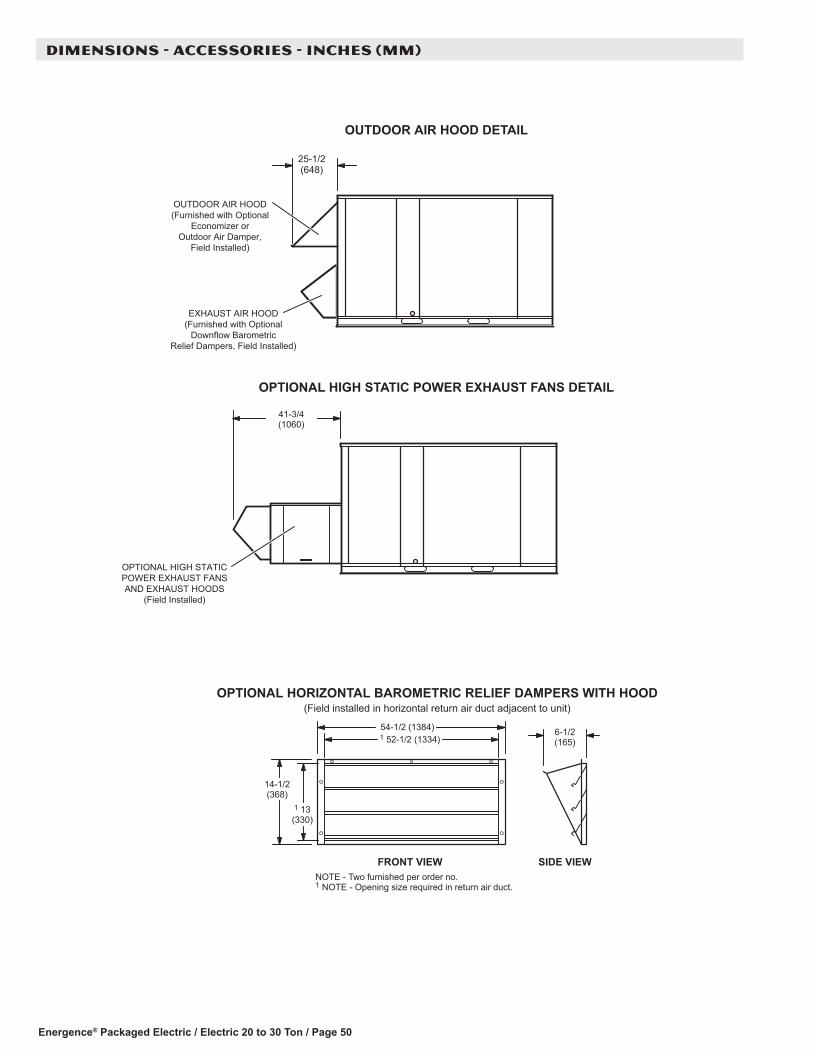
Energence® Packaged Electric / Electric 20 to 30 Ton / Page 50
DIMENSIONS - ACCESSORIES - INCHES (MM)
OUTDOOR AIR HOOD DETAIL
25-1/2(648)
OPTIONAL HIGH STATICPOWER EXHAUST FANSAND EXHAUST HOODS
(Field Installed)
OPTIONAL HIGH STATIC POWER EXHAUST FANS DETAIL
41-3/4(1060)
OPTIONAL HORIZONTAL BAROMETRIC RELIEF DAMPERS WITH HOOD(Field installed in horizontal return air duct adjacent to unit)
FRONT VIEW SIDE VIEW
54-1/2 (1384)
14-1/2(368)
1 13(330)
6-1/2(165)1 52-1/2 (1334)
NOTE - Two furnished per order no. 1 NOTE - Opening size required in return air duct.
OUTDOOR AIR HOOD(Furnished with Optional
Economizer orOutdoor Air Damper,
Field Installed)
EXHAUST AIR HOOD(Furnished with Optional
Downflow BarometricRelief Dampers, Field Installed)

Energence® Packaged Electric / Electric 20 to 30 Ton / Page 51
DIMENSIONS - ACCESSORIES - INCHES (MM)
RETURNOPENING
SUPPLYOPENING
NOTE - Roof deck may be omitted within confines of curb.
TYPICAL FLASHING DETAIL FOR ROOF CURB
ROOF CURB(Extends around entire
perimeter of unit)
FIBERGLASSINSULATION
(Furnished)COUNTER FLASHING(Field Supplied)
BASE BOTTOM
RIGID INSULATION(Field Supplied)
ROOFINGMATERIAL
CANT STRIP(Field Supplied)
PACKAGEDUNIT
NAILER STRIP(Furnished)
DETAIL ROOF CURB
FACTORY INSTALLEDPERIMETER WOODNAILER STRIP
HYBRID ROOF CURBS - DOUBLE DUCT OPENING
14 (356)18 (457)24 (610)
1-3/4(44)
1/2 (13)
1-3/4(44)
14 (356)18 (457)24 (610)
111-5/8(2835)
86-1/8(2188)
82-5/8(2099)
21(533)
17(432)
16(406)
61-1/2(1562)
13-1/4(337)
2(51)
79-1/2(2019) 115-1/8
(2924)

Energence® Packaged Electric / Electric 20 to 30 Ton / Page 52
DIMENSIONS - ACCESSORIES - INCHES (MM)
ROOF CURBS WITH SUPPLY & RETURN AIR TRANSITIONS FOR CEILING DIFFUSERS
A
LASRT RETURNTRANSITION
LASRT SUPPLYTRANSITION
RETURNAIR OPENING
SUPPLY AIROPENINGS
TOP VIEW
54(1372)
3/4(19) Typ.
4-1/2 (114)
SUPPORTANGLE
(Furnished withTransitions)
TRANSITION DETAIL
80-3/4 (2051)
28(711)
60 (1524)
60 (1524)
ASECTION B-B
26-1/2(673)
28(711)
28(711)4-1/2
(114)
28(711)
LAS
RT
RE
TUR
NTR
AN
SIT
ION
LAS
RT
SU
PP
LYTR
AN
SIT
ION
14(356)
2(51)
12(305)
1-1/2(38) Typ.
26-1/2(673)

Energence® Packaged Electric / Electric 20 to 30 Ton / Page 53
DIMENSIONS - ACCESSORIES - INCHES (MM)
HORIZONTAL ROOF CURBS − Requires Optional Horizontal Return Air Panel Kit
13-1/4(337)
1 26 (660)C1CURB15C-11 37 (940)C1CURB17C-1
6-1/2 (165)C1CURB15C-117-1/2 (445)C1CURB17C-11 NOTE − Top of Curb extends 4 inch (102 mm) inside
bottom of unit base. See Typical Flashing Detail. SIDE VIEW(Horizontal Openings)
HORIZONTAL ROOF CURB(Required For Horizontal Applications)
HORIZONTAL RETURNAIR OPENING
5-1/4(133)
15 (381)78-1/2 (1994)
65(1651)
HORIZONTALSUPPLY AIR OPENING
75 (1905)18 (457)
2 (51)
91 (2311)C1CURB15C-1102 (2591)C1CURB17C-1
OPTIONAL RETURN AIR PANEL KIT(Required For Horizontal Applications)
42-7/8(1089)
HORIZONTAL SUPPLY AND RETURN AIR OPENINGSROOFTOP UNIT WITH HORIZONTAL ROOF CURB
1 C1CURB15C-1 2 C1CURB17C-1
102-1/8 (2594)
SIDE VIEW
TOP VIEW
Fram
eO
peni
ng
FrameOpening
54(1372)
98-1/2 (2502)
82-5/8(2099)
86-5/8 (2200)
98-1/2 (2502)
FRONT VIEW102-1/2 (2604)
CURB SUPPLY AIR OPENINGWith 1-1/2 in. (38 mm) FLANGE
75 (1905)
5-1/2 (140)
SUPPLYDUCT
PANELS(Furnished)
SUPPLY AIRTURNING VANE
(Furnished)
102-1/8 (2594) 86-1/4 (2191)
NOTE − Roof deck may be omitted within confines of curb.
SUPPLY AIRTURNING VANE
(Furnished)
PANEL TO COVER RETURN AIR OPENING IN BOTTOM OF UNIT(Furnished With Optional Horizontal Return Air Panel Kit)
SIDE VIEW(PACKAGED UNIT)
1-13/16 (46)
1-13/16(46)
1-13/16 (46)
1,2 13-1/4 (337)
1 6-1/2 (165)2 17-1/2 (445)
1 30 (762)2 41 (1041)
1, 2 18 (457)
NOTE - C1CURB15C-1 is designed for horizontal discharge when unit is mounted on a slab. C1CURB17C-1 is designed for horizontal discharge when unit is mounted on a rooftop.
86-1/4(2191)
1 26 (660)2 37 (940)3 30 (762)4 41 (1041)
1 (25)
2 (51)SECTION A-A
1-13/16 (46)
AA
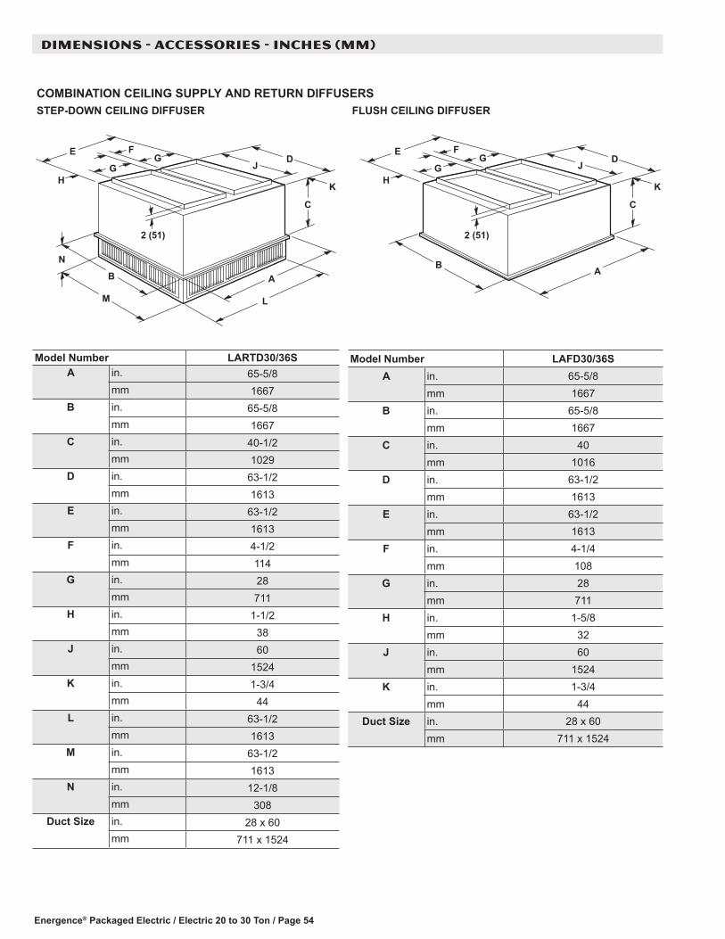
Energence® Packaged Electric / Electric 20 to 30 Ton / Page 54
DIMENSIONS - ACCESSORIES - INCHES (MM)
COMBINATION CEILING SUPPLY AND RETURN DIFFUSERSRESUFFID GNILIEC HSULFRESUFFID GNILIEC NWOD-PETS
L
A
C
HJG
FE
B
M
N
K
DG
2 (51)
A
C
HJG
FE
B
K
DG
2 (51)
Model Number LARTD30/36SA in. 65-5/8
mm 1667B in. 65-5/8
mm 1667C in. 40-1/2
mm 1029D in. 63-1/2
mm 1613E in. 63-1/2
mm 1613F in. 4-1/2
mm 114G in. 28
mm 711H in. 1-1/2
mm 38J in. 60
mm 1524K in. 1-3/4
mm 44L in. 63-1/2
mm 1613M in. 63-1/2
mm 1613N in. 12-1/8
mm 308Duct Size in. 28 x 60
mm 711 x 1524
Model Number LAFD30/36SA in. 65-5/8
mm 1667B in. 65-5/8
mm 1667C in. 40
mm 1016D in. 63-1/2
mm 1613E in. 63-1/2
mm 1613F in. 4-1/4
mm 108G in. 28
mm 711H in. 1-5/8
mm 32J in. 60
mm 1524K in. 1-3/4
mm 44Duct Size in. 28 x 60
mm 711 x 1524


NOTE - Due to Lennox’ ongoing commitment to quality, Specifications, Ratings and Dimensions subject to change without notice and without incurring liability. Improper installation, adjustment, alteration, service or maintenance can cause property damage or personal injury. Installation and service must be performed by a qualified installer and servicing agency. ©2018 Lennox Industries, Inc.
Visit us at www.lennox.com For the latest technical information, www.lennoxcommercial.com Contact us at 1-800-4-LENNOX
REVISIONS
REVISIONS
Section Description
Options/Accessories Updated catalog numbers for SCR Heat option for Thermostat and Duct Sensor.
Specifications Added AHRI Reference Numbers.