ase 200 accelerated solvent extractor operator's manual
TRANSCRIPT

ASE® 200 ACCELERATED SOLVENT EXTRACTOR
OPERATOR’S MANUAL
© 1999 Dionex Corporation
Document No. 031149Revision 04
December 1999

©1999 by Dionex CorporationAll rights reserved worldwide.Printed in the United States of America.
This publication is protected by federal copyright law. No part of this publicationmay be copied or distributed, transmitted, transcribed, stored in a retrieval system,or transmitted into any human or computer language, in any form or by any means,electronic, mechanical, magnetic, manual, or otherwise, or disclosed to third partieswithout the express written permission of Dionex Corporation, 1228 Titan Way,Sunnyvale, California 94088-3603 U.S.A.
DISCLAIMER OF WARRANTY AND LIMITED WARRANTY
THIS PUBLICATION IS PROVIDED “AS IS” WITHOUT WARRANTY OFANY KIND. DIONEX CORPORATION DOES NOT WARRANT,GUARANTEE, OR MAKE ANY EXPRESS OR IMPLIEDREPRESENTATIONS REGARDING THE USE, OR THE RESULTS OF THEUSE, OF THIS PUBLICATION IN TERMS OF CORRECTNESS,ACCURACY, RELIABILITY, CURRENTNESS, OR OTHERWISE.FURTHER, DIONEX CORPORATION RESERVES THE RIGHT TO REVISETHIS PUBLICATION AND TO MAKE CHANGES FROM TIME TO TIMEIN THE CONTENT HEREINOF WITHOUT OBLIGATION OF DIONEXCORPORATION TO NOTIFY ANY PERSON OR ORGANIZATION OFSUCH REVISION OR CHANGES.
TRADEMARKS
AutoASE , AutoSeal , and DX-LAN are trademarks of Dionex Corporation.ASE® 200 is a registered trademark of Dionex Corporation.N-EVAP is a trademark of Organomation Associates, Inc.Teflon®, Tefzel®, and Viton® are registered trademarks of E.I. duPont de Nemours& Co.TurboVap® is a registered trademark of Zymark Corporation.
PRINTING HISTORY
Revision 01, June 1995Revision 02, February 1996Revision 03, March 1997Revision 04, December 1999
Contents
1 • Introduction
1.1 ASE 200 Options . . . . . . . . . . . . . . . . . 1-2
1.2 About This Manual . . . . . . . . . . . . . . . . 1-3
1.2.1 Typefaces . . . . . . . . . . . . . . . . . 1-3
1.2.2 Safety Messages and Notes . . . . . . . 1-4
1.2.3 Symbols . . . . . . . . . . . . . . . . . . 1-5
2 • Description
2.1 Operating Features . . . . . . . . . . . . . . . . 2-1
2.1.1 Control Panel Display . . . . . . . . . . 2-3
2.1.2 Control Panel Keypad . . . . . . . . . . 2-5
2.1.3 Sample Cells, Rinse Tubes, and Cell Tray . . . . . . . . . . . . . . . . . 2-7
2.1.4 Collection Vials, Rinse Vials, and Vial Tray . . . . . . . . . . . . . . . . . 2-8
2.1.5 Solvent Reservoir Compartment . . . . 2-9
2.1.6 Electronics Area . . . . . . . . . . . . . 2-10
2.2 Extraction Process . . . . . . . . . . . . . . . . . 2-11
2.3 Operating Modes . . . . . . . . . . . . . . . . . 2-22
2.3.1 Local Mode . . . . . . . . . . . . . . . . 2-22
2.3.2 Remote Mode . . . . . . . . . . . . . . . 2-22
2.4 Method and Schedule Control . . . . . . . . . . 2-23
Doc. 031149-04 12/99 i

3 • Operation and Maintenance
3.1 Preparing to Run . . . . . . . . . . . . . . . . . 3-1
3.1.1 Solvent Selection and Preparation . . . 3-1
3.1.2 Filling the Solvent Reservoir . . . . . . 3-2
3.1.3 Sample Preparation . . . . . . . . . . . 3-4
3.1.4 Cell Selection and Filling . . . . . . . . 3-6
3.1.5 Vial Selection and Loading . . . . . . . 3-11
3.1.6 Rinsing/Priming the System . . . . . . . 3-14
3.1.7 Automatic Rinsing Between Samples . 3-15
3.1.8 Operation with an External Device . . . 3-16
3.2 Methods and Schedules . . . . . . . . . . . . . . 3-24
3.2.1 Creating Methods . . . . . . . . . . . . 3-25
3.2.2 Example Methods . . . . . . . . . . . . 3-30
3.2.3 Creating Schedules . . . . . . . . . . . . 3-34
3.2.4 Example Schedules . . . . . . . . . . . 3-36
3.3 Method Development Guidelines . . . . . . . . 3-40
3.4 Running Extractions . . . . . . . . . . . . . . . . 3-42
3.4.1 Running Under Method Control . . . . 3-42
3.4.2 Running Under Schedule Control . . . . 3-45
3.4.3 Aborting a Run . . . . . . . . . . . . . . 3-46
3.5 Post-Extraction Procedures . . . . . . . . . . . . 3-47
3.5.1 Cleaning the Cells . . . . . . . . . . . . 3-47
3.5.2 Processing Extracts . . . . . . . . . . . 3-47
3.6 Printing Reports . . . . . . . . . . . . . . . . . . 3-48
3.7 Routine Maintenance . . . . . . . . . . . . . . . 3-49
3.7.1 Daily Maintenance . . . . . . . . . . . . 3-49
3.7.2 Periodic Maintenance . . . . . . . . . . 3-49
3.8 Shutdown . . . . . . . . . . . . . . . . . . . . . . 3-51
Contents
ii Doc. 031149-04 12/99

4 • Troubleshooting
4.1 Error Messages . . . . . . . . . . . . . . . . . . 4-1
4.2 System Stopped . . . . . . . . . . . . . . . . . . 4-20
4.3 Liquid Leaks . . . . . . . . . . . . . . . . . . . . 4-22
4.4 Gas/Air Leaks . . . . . . . . . . . . . . . . . . . 4-24
4.5 Reports Do Not Print . . . . . . . . . . . . . . . 4-25
5 • Service
5.1 Replacing the Cell PEEK Seal and Teflon O-Ring . . . . . . . . . . . . . . . . . . . 5-2
5.2 Replacing Tubing and Fittings . . . . . . . . . . 5-3
5.3 Cleaning and/or Replacing Pump Check Valves . . . . . . . . . . . . . . . . . . . . 5-4
5.4 Replacing Piston Seals . . . . . . . . . . . . . . 5-7
5.5 Replacing the Pressure Relief Valve . . . . . . . 5-10
5.6 Replacing the Static Valve . . . . . . . . . . . . 5-11
5.7 Replacing Needles . . . . . . . . . . . . . . . . . 5-12
5.7.1 Vent Needle . . . . . . . . . . . . . . . . 5-12
5.7.2 Source Needle . . . . . . . . . . . . . . 5-14
5.8 Changing the Main Power Fuses . . . . . . . . . 5-15
5.9 Calibrating the Hydrocarbon Sensor . . . . . . . 5-16
5.10 Replacing the Hydrocarbon Sensor . . . . . . . 5-18
A • Specifications
A.1 Electrical . . . . . . . . . . . . . . . . . . . . . . A-1
A.2 Environmental . . . . . . . . . . . . . . . . . . . A-1
A.3 Physical . . . . . . . . . . . . . . . . . . . . . . A-1
A.4 Pneumatic . . . . . . . . . . . . . . . . . . . . . A-1
Contents
Doc. 031149-04 12/99 iii
A.5 Display and Keypad . . . . . . . . . . . . . . . . . A-2
A.6 Extraction Cells and Tray . . . . . . . . . . . . . . A-2
A.7 Collection Vials and Trays . . . . . . . . . . . . . A-2
A.8 Interior Components . . . . . . . . . . . . . . . . A-2
B • Installation
B.1 Facility Requirements . . . . . . . . . . . . . . . . B-1
B.2 Installation Instructions . . . . . . . . . . . . . . . B-2
B.2.1 Air/Nitrogen Connections . . . . . . . . . B-2
B.2.2 Electrical Connections . . . . . . . . . . . B-5
B.2.3 DX-LAN Network Connections(Optional) . . . . . . . . . . . . . . . . . . B-7
B.2.4 Check Pressure Readings . . . . . . . . . B-9
B.2.5 Solvent Reservoir CompartmentConnections . . . . . . . . . . . . . . . . B-11
B.2.6 Vial Tray Installation . . . . . . . . . . . B-15
B.2.7 Cell and Rinse Tube Inspection . . . . . . B-15
B.2.8 Power-Up . . . . . . . . . . . . . . . . . . B-17
B.2.9 Rinsing/Priming the System . . . . . . . . B-18
B.3 Module Setup . . . . . . . . . . . . . . . . . . . . B-19
B.4 Printer Connections (Optional) . . . . . . . . . . . B-22
C • Diagnostic Screens
C.1 Power-Up Screen . . . . . . . . . . . . . . . . . . C-1
C.2 Regulators Screen . . . . . . . . . . . . . . . . . . C-2
C.3 Error Log Screen . . . . . . . . . . . . . . . . . . C-4
C.4 Hydrocarbon Calibration Screen . . . . . . . . . . C-5
D • Reordering Information
Contents
iv Doc. 031149-04 12/99
E • TTL and Relay Control
E.1 TTL and Relay Output Operation . . . . . . . . . E-1
E.2 TTL Input Operation . . . . . . . . . . . . . . . . E-1
E.2.1 TTL Input Signal Modes . . . . . . . . . E-2
Index
Contents
Doc. 031149-04 12/99 v

Contents
vi Doc. 031149-04 12/99

1 • Introduction
The ASE® 200 Accelerated Solvent Extractor is an automatedsystem for extracting organic compounds from a variety of solid andsemisolid samples. The ASE 200 accelerates the traditionalextraction process by using solvent at elevated temperatures.Pressure is applied to the sample extraction cell to maintain theheated solvent in a liquid state during the extraction. After heating,the extract is flushed from the sample cell into a standard collectionvial and is ready for analysis.
Figure 1-1. ASE 200 Accelerated Solvent Extractor
Doc. 031149-04 12/99 1-1
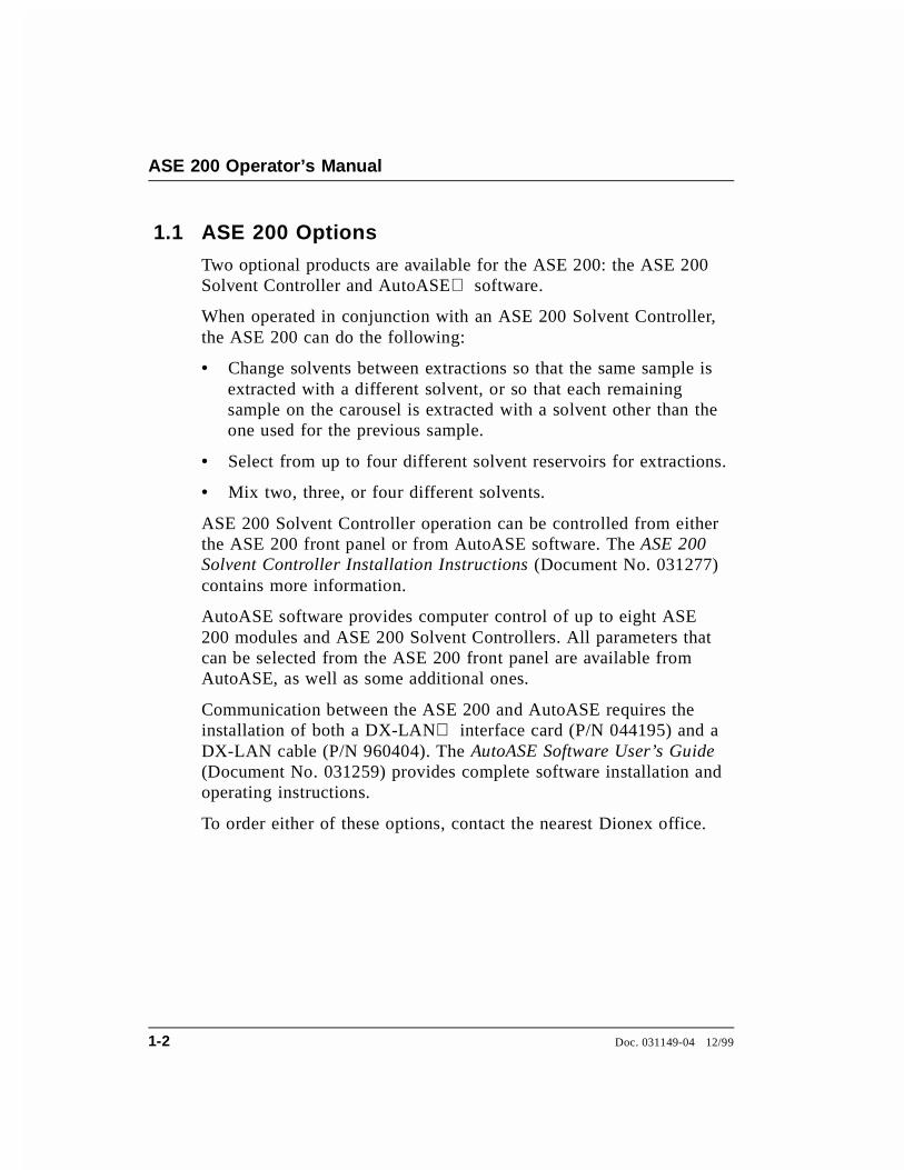
1.1 ASE 200 Options
Two optional products are available for the ASE 200: the ASE 200Solvent Controller and AutoASE software.
When operated in conjunction with an ASE 200 Solvent Controller,the ASE 200 can do the following:
• Change solvents between extractions so that the same sample isextracted with a different solvent, or so that each remainingsample on the carousel is extracted with a solvent other than theone used for the previous sample.
• Select from up to four different solvent reservoirs for extractions.
• Mix two, three, or four different solvents.
ASE 200 Solvent Controller operation can be controlled from eitherthe ASE 200 front panel or from AutoASE software. The ASE 200Solvent Controller Installation Instructions (Document No. 031277)contains more information.
AutoASE software provides computer control of up to eight ASE200 modules and ASE 200 Solvent Controllers. All parameters thatcan be selected from the ASE 200 front panel are available fromAutoASE, as well as some additional ones.
Communication between the ASE 200 and AutoASE requires theinstallation of both a DX-LAN interface card (P/N 044195) and aDX-LAN cable (P/N 960404). The AutoASE Software User’s Guide(Document No. 031259) provides complete software installation andoperating instructions.
To order either of these options, contact the nearest Dionex office.
ASE 200 Operator’s Manual
1-2 Doc. 031149-04 12/99
1.2 About This Manual
Chapter 1, Introduction, introduces the ASE 200 and explains theconventions used in this manual (including safety-related messages).
Chapter 2, Description, describes the physical aspects of theASE 200 and the extraction process.
Chapter 3, Operation and Maintenance, discusses operatingprocedures and presents several examples of how to create and runmethods and schedules. Routine preventive maintenancerequirements are included.
Chapter 4, Troubleshooting, lists minor operating problems andprovides step-by-step procedures to isolate and eliminate theirsources.
Chapter 5, Service, presents step-by-step instructions for routineservice and parts replacement procedures.
Appendix A, Specifications, contains the ASE 200 specificationsand installation site requirements.
Appendix B, Installation, describes how to install the ASE 200.
Appendix C, Diagnostic Screens, describes the ASE 200 diagnosticscreens.
Appendix D, Reordering Information, lists spare parts.
Appendix E, TTL and Relay Control, describes relay and TTLinput and output functions.
1.2.1 Typefaces
• Capitalized bold type indicates a front panel button:
Press Start to begin running the method.
• Uppercase bold type indicates the name of a menu, ascreen, or an on-screen field:
Display the METHOD EDITOR screen.
Move the cursor to the EDIT# field.
1 • Introduction
Doc. 031149-04 12/99 1-3

1.2.2 Safety Messages and Notes
The ASE 200 meets European, EMC, and safety requirementsper Council Directives 73/23/EEC and 89/336/EEC, EN61010-1:1993 (safety), EN 50082-1:1992 (susceptibility), andEN 55011:1991 (emissions). The CE and GS safety label onthe ASE 200 attests to compliance with these standards.
To ensure operator safety, do not use the ASE 200 for anyapplications other than those described in this manual. Ifthere is a question regarding appropriate usage, contactDionex before proceeding.
This manual contains warnings and precautionary statementsthat, when properly followed, can prevent personal injury tothe user and/or damage to the ASE 200. Safety messagesappear in bold type and are accompanied by icons.
Indicates an imminently hazardous situation which, if notavoided, will result in death or serious injury.
Indicates a potentially hazardous situation which, if notavoided, may result in death or serious injury.
Indicates a potentially hazardous situation which, if notavoided, may result in minor or moderate injury.
Indicates that the function or process of the instrumentmay be impaired. Operation does not constitute a hazard.
ASE 200 Operator’s Manual
1-4 Doc. 031149-04 12/99

Informational messages also appear throughout this manual.These are labeled NOTE and are in bold type:
NOTENOTES call attention to certain information. They alertthe user to an unexpected result of an action, suggest howto optimize instrument performance, etc.
1.2.3 Symbols
The symbols below appear on the ASE 200 or on ASE 200labels.
Alternating current
Protective conductor terminal
Power supply is on
Power supply is off
~
1 • Introduction
Doc. 031149-04 12/99 1-5

ASE 200 Operator’s Manual
1-6 Doc. 031149-04 12/99

2 • Description
• Section 2.1 describes the operating features and components ofthe ASE 200.
• Section 2.2 describes the extraction process.
• Section 2.3 describes the two operating modes for the ASE 200.
• Section 2.4 describes both method and schedule control of theASE 200.
2.1 Operating Features
Figure 2-1 illustrates the main operating features of the ASE 200.
Vial Tray
Collection VialSolvent ReservoirCompartment
Control Panel
Power Switch
Cell Tray
Sample ExtractionCell
NeedleMechanism
Oven Area(behind safety covers)Electronics Area
(behind upper door)
Figure 2-1. ASE 200 Operating Features
Doc. 031149-04 12/99 2-1
Power Switch
The power switch actuator is at the lower left corner of the upperdoor. The door must be fully closed for the actuator to operate.When the upper door is open, press the main power switch, locatedbehind the door, to turn the ASE 200 on and off.
Control Panel
The control panel on the upper door of the ASE 200 contains theliquid crystal display (LCD) and the membrane keypad (seeFigure 2-2). The upper door provides access to the ASE 200electronics.
Solvent Reservoir Compartment
The lower door provides access to the solvent reservoir, the wastevial, and the pressure gauges.
Cell Tray and Extraction Cells
The cell tray, on the upper right of the ASE 200, holds the sampleextraction cells. The prepared sample is loaded into these cells.
Vial Tray and Collection Vials
The vial tray, on the lower right, holds the collection vials. Afterextraction, these vials contain solvent and the analytes extractedfrom the sample.
Oven Area
The oven is housed at the rear of the ASE 200. This area also housesthe AutoSeal arms, which move the cell into and out of the oven,and which seal the cell during the extraction.
Needle Mechanism
The needle mechanism, at the left of the vial tray, pierces thecollection vial septum, allowing the extract to flow from the cell intothe vial.
ASE 200 Operator’s Manual
2-2 Doc. 031149-04 12/99

2.1.1 Control Panel Display
The LCD, also called the screen, displays status andoperating information. Fields on the screen that are in reversevideo (blue letters on white background) can be edited.Normal video fields display information only.
8TIME FUNCTION IN
9 EXTNL INTERFACE
Pow er Sw itchA ctu ator
Tab(for o peningthe d oo r)
Tab(for tiltin gthe p an el)
K nob(for ad justin g th escreen con trast)
LC DM em b ran eK eypad
�
�
7,0( )81&7,21 ,1
',$*1267,& 0(18
(;71/ ,17(5)$&(��
7,0( )81&7,21 ,1
',$*1267,& 0(18
/2$' 0(7+2'�6&+('8/(
&855(17 67$786
0(7+2' (',725
6&+('8/( (',725
02'8/( 6(783
&20081,&$7,21
(;71/ ,17(5)$&(
Figure 2-2. ASE 200 Control Panel
2 • Description
Doc. 031149-04 12/99 2-3

Three adjustments are available for improving screenvisibility:
• The screen contrast can be adjusted with the knurled knobin the recess below the keypad (see Figure 2-2).
• The brightness of the screen’s backlight can be adjustedby resetting this option on the MODULE SETUP screen (seeSection B.3).
• The control panel can be tilted to four positions. To tiltthe panel, support the upper door of the enclosure at theleft side (to prevent it from opening) and lift firmly on thetab in the middle of the recess below the keypad (seeFigure 2-2). Push on the tab to return the panel to itsvertical position.
At power-up, the copyright and microprocessor code revisionlevels are displayed for a few seconds before the MENU OF
SCREENS appears. From the menu, select either an individualoperational screen or the DIAGNOSTIC MENU screen.
There are two ways to select a screen from the menu:
• Press the number button that corresponds to the screen’snumber on the menu (1–9).
• Move the cursor to the screen name and press Enter.
ASE 200 Operator’s Manual
2-4 Doc. 031149-04 12/99

2.1.2 Control Panel Keypad
Unless the ASE 200 is under computer control, pressing akeypad button either directly affects ASE 200 operation oraffects a screen function. Table 2-1 summarizes the buttonfunctions.
Button Function
The following buttons affect ASE 200 operation directly:
Pressing the Trays button toggles the cell and vial traysbetween the engaged and free spin modes. LEDs on thebutton indicate the current mode. When the left LED islighted, the vial and cell trays can be rotated manually.Switch to free spin during loading and unloading of vialsand cells, and when removing the vial tray from its supportspindle.
When the right LED is lighted, the tray drive mechanismsare engaged and cannot be moved manually. Toggling fromfree spin to engaged causes the trays to rotate to the homeposition (i.e., vial 1 and cell 1 are ready for the next run).Starting a run automatically engages the trays. The Traysbutton is disabled during a run.
Starts a manual rinse cycle, which is used to prime the pumpand to rinse after a solvent change. The trays rotate to thenearest rinse vial and rinse tube. Approximately 4 mL ofsolvent is then pumped through the system and into the rinsevial. This button functions only when ASE is idle.
Starts the currently loaded method or schedule. When thesystem is idle, the LED on the left side of the button islighted. When a run is in progress, the LED on the right islighted. This button is disabled when the ASE 200 is inRemote mode.
Interrupts the current run. The pump turns off, valves close,and all flow stops. The screen displays a list of options forselection. See Section 3.4.3 for more information.
Table 2-1. Front Panel Button Functions
Trays
(F re e S p in )
Tray s
(E n g ag ed )
S tart
S ta rt
( Id le )
(R u n n in g )
2 • Description
Doc. 031149-04 12/99 2-5

Button Function
The following buttons control functions:
From the SCHEDULE EDITOR screen, press Alt followed bySelect ∆ to delete the current line and move up the linesbelow the deleted line. Press Alt followed by Select ∇ toinsert a new line. This button is disabled when the ASE 200is in Remote mode.
Removes the value from the current entry field. This buttonis disabled when the ASE 200 is in Remote mode.
The Select buttons cycle between predetermined options inentry fields. To confirm the selected value, press Enter ormove the cursor out of the field by pressing an arrow button.In fields that have predetermined numeric choices, Select ∆increases the value by one unit and Select ∇ decreases thevalue by one unit. Holding down a Select button increases(or decreases) the value continuously.
The arrow buttons move the cursor in the direction of thearrow to the next entry field if one exists. At the end of aline, the left arrow wraps the cursor around to the next entryfield on the line above; the right arrow wraps the cursor tothe next entry field on the line below. The up and downarrows do not wrap around.
After entering a new value in an entry field, pressing anarrow button to move to another field saves the change.
Displays a context-sensitive help screen.
Displays a list of the available screens.
The numeric buttons enter the selected number into thecurrent entry field. From a menu, pressing a numeric buttonopens the corresponding screen.
Saves changes made in entry fields. When a menu screen isdisplayed, pressing Enter opens the highlighted screen.
Table 2-1. Front Panel Button Functions (continued)
6HOHFW
6HOHFW
ASE 200 Operator’s Manual
2-6 Doc. 031149-04 12/99

NOTEAppendix D contains part numbers for cells, vials, andother consumable accessories.
2.1.3 Sample Cells, Rinse Tubes, and Cell Tray
The cell tray holds 24 sample cells and four rinse tubes.Sample cells are available in the following sizes: 1 mL,5 mL, 11 mL, 22 mL, and 33 mL. Interchangeable caps screwonto each end of the cell body and are hand-tightened. Insideeach cap is a stainless steel frit and a PEEK seal. During arun, the cell caps are compressed to form a tight seal betweenthe caps and the cell body.
The sealing surfaces of the 1 mL and 5 mL cells are largerthan those of the standard cells (11 mL, 22 mL, and 33 mL).Before installing an end cap previously used on a standardcell onto either a 1 mL or 5 mL cell body, first install a newPEEK seal in the cap (see Section 5.1).
Each cell cap contains an external O-ring. A Teflon® O-ring(P/N 049457, pkg. of 50) is standard. Use a Viton® O-ring(P/N 056325, pkg. of 50) for high temperature applications,such as dioxins.
Install the sample cells in any order. During a run, sensorsdetermine the cell size in each tray position.
To avoid personal injury, exercise caution when the tray isin motion.
Rinse tubes are small-diameter metal tubes that fit into thefour rinse positions in the cell tray (see Figure 2-3). During arinse cycle, the tray rotates to the nearest rinse position thatensures that the heated cells remain behind the safety coverover the oven (see Figure 2-1). Solvent passes directlythrough the rinse tube during the cycle.
2 • Description
Doc. 031149-04 12/99 2-7
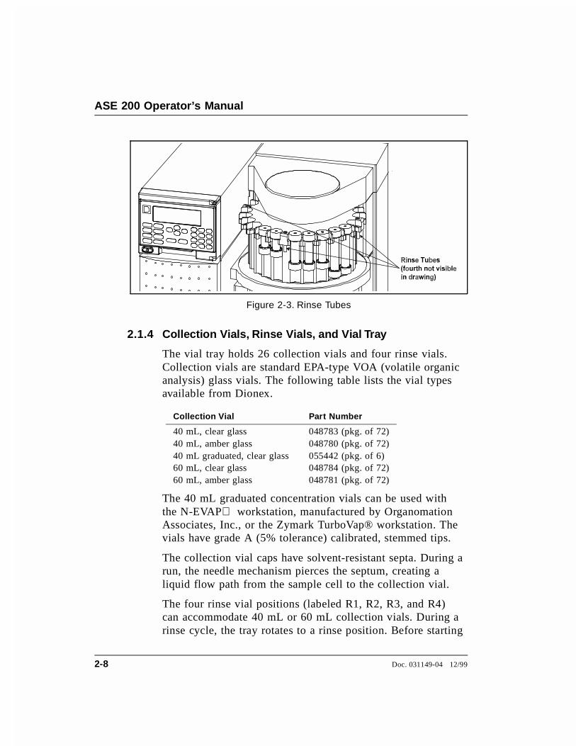
2.1.4 Collection Vials, Rinse Vials, and Vial Tray
The vial tray holds 26 collection vials and four rinse vials.Collection vials are standard EPA-type VOA (volatile organicanalysis) glass vials. The following table lists the vial typesavailable from Dionex.
Collection Vial Part Number
40 mL, clear glass 048783 (pkg. of 72)40 mL, amber glass 048780 (pkg. of 72)40 mL graduated, clear glass 055442 (pkg. of 6)60 mL, clear glass 048784 (pkg. of 72)60 mL, amber glass 048781 (pkg. of 72)
The 40 mL graduated concentration vials can be used withthe N-EVAP workstation, manufactured by OrganomationAssociates, Inc., or the Zymark TurboVap® workstation. Thevials have grade A (5% tolerance) calibrated, stemmed tips.
The collection vial caps have solvent-resistant septa. During arun, the needle mechanism pierces the septum, creating aliquid flow path from the sample cell to the collection vial.
The four rinse vial positions (labeled R1, R2, R3, and R4)can accommodate 40 mL or 60 mL collection vials. During arinse cycle, the tray rotates to a rinse position. Before starting
Figure 2-3. Rinse Tubes
ASE 200 Operator’s Manual
2-8 Doc. 031149-04 12/99
the rinse, if the vial sensors determine that the rinse vial isabsent or full, the tray rotates to another rinse position.Solvent is then pumped through the system and collected inthe rinse vial.
To avoid personal injury, exercise caution whenever thetray is in motion.
To adapt the vial tray positions for regular 40 mL vials,install removable inserts (P/N 049348) into the tray positions.To adapt the tray positions for graduated 40 mL vials, installvial spacers (P/N 055444) into the tray positions.
No inserts or spacers are required for the 60 mL vials.
2.1.5 Solvent Reservoir Compartment
The compartment behind the front lower door (see Figure2-1) contains the solvent reservoir, waste vial, and pressuregauges.
The ASE 200 Ship Kit includes a 2-liter glass reservoir withshatterproof plastic coating (P/N 045901) and a bottle capassembly (P/N 049496) with tubing and fittings forconnecting the reservoir to the ASE 200.
NOTEWhen an ASE 200 Solvent Controller is in use, install thesolvent reservoirs in the Solvent Controller, not the ASE200 reservoir compartment.
A 40 mL or 60 mL collection vial can be used to collectwaste. The waste vial sits in a holder on the right side of thereservoir compartment. Two vent lines, one from the pressurerelief valve and one from the needle mechanism, areconnected to the top of the waste vial holder. The waste vialcollects the small amounts of solvent vented through the twolines.
2 • Description
Doc. 031149-04 12/99 2-9
A vent outlet line is also connected to the waste vial holder.Gas is vented out this line to the rear panel, which can beconnected to a hood. The ASE 200 Ship Kit includesadditional vent tubing for this purpose.
Check the waste vial daily and empty whenever necessary.
2.1.6 Electronics Area
The ASE 200 electronics area is located behind the upperfront door (see Figure 2-1). To open the door, pull on the tablocated to the right of the main power actuator (seeFigure 2-2).
A strip of eight 2-pin connectors (two relay outputs, two TTLoutputs, and two TTL inputs) on the CPU card (seeFigure B-15) allows the ASE 200 to communicate with anexternal sample preparation device. See Section 3.1.8 fordetails about implementing this feature.
Do not remove any of the electronics cards. There are nouser-serviceable components on the cards. If servicing isrequired, it must be performed by qualified personnel andappropriate electrostatic discharge (ESD) handlingprocedures must be followed.
ASE 200 Operator’s Manual
2-10 Doc. 031149-04 12/99

2.2 Extraction Process
Before starting an extraction, perform the following steps. Refer toChapter 3 for instructions.
• Prepare samples and load them into the extraction cells.
• Place cells in the cell tray.
• Place collection vials in the vial tray.
• Create a method.
• Load the method.
The remainder of this section describes the automatic portion of theextraction process—the steps that the ASE 200 performs after youpress Start to begin a run.
The extraction process consists of eight main steps:
• Loading the cell into the oven
• Filling the cell with solvent
• Heating the cell (equilibration)
• Static extraction
• Flushing with fresh solvent
• Purging solvent from the system
• End relief
• Unloading the cell
Figure 2-4 shows the solvent and gas flow path through keycomponents of the ASE 200.
2 • Description
Doc. 031149-04 12/99 2-11

During the extraction process, the CURRENT STATUS screen displaysthe step being run, as well as other operating parameters. Figure 2-5is an example of the CURRENT STATUS screen. Table 2-2 describes thescreen parameters.
To NSupply
2
To Vent onRear Panel
To Vent onRear Panel
Figure 2-4. ASE 200 Schematic
6<67(0 67$786� ),//,1* &(//&21752/�67(3 7,0(�7(03(5$785(�35(6685(�67$7,&385*(
0(7+2' 6&+('8/(�0(7+2'�
9,$/�
&(//�
/2&$/
&(// 6,=(�
92/80( �P/��
�
�
���
�
��� �������
&38035(/,()
2&
���&SVL
2
°
Figure 2-5. Current Status Screen
ASE 200 Operator’s Manual
2-12 Doc. 031149-04 12/99

If no keypad buttons are pressed for a specified duration, analternate status screen replaces the CURRENT STATUS screen (seeFigure 2-6). Press any button to return to the CURRENT STATUS
screen. To change the time delay for displaying the alternate statusscreen or to disable the screen, see Section B.3.
Parameter Description
SYSTEM STATUS Current step (load, fill, heat, static, flush, purge, unload)
CONTROL Current control type (method or schedule)
STEP TIME Step’s programmed time is first, followed by the elapsedtime
TEMPERATURE Programmed temperature is first, followed by the currenttemperature
PRESSURE Programmed pressure is first, followed by the currentpressure
STATIC PUMPPURGE RELIEF
Status of valves (C=closed, O=open)
SCHEDULE Current schedule (if any)
METHOD Current method
CELL Current cell
CELL SIZE Size of the cell (1 mL, 5 mL, 11 mL, 22 mL, or 33 mL).Note: This field displays “11” when a 1 mL or 5 mL cell ispresent because the length of these cells is equivalent to thelength of the 11 mL cell.
VIAL Current vial
VOLUME (mL) Approximate amount of solvent delivered by the pump
Table 2-2. Current Status Screen Parameters
Figure 2-6. Alternate Status Screen
2 • Description
Doc. 031149-04 12/99 2-13

The following sections describe each step in the extraction process.
NOTEThe oven begins heating to the programmed set pointimmediately after a method is loaded (before you press Start tobegin the run). Cell loading begins when the oven is within 5 °Cof the set point.
Step 1: Loading the Cell
• The cell and vialtrays rotate to theinitial positionsspecified in themethod orschedule. Theneedle mechanismpierces the vial.
• The AutoSeal armspick up the celland move it intothe oven.
• The oven appliespressure to sealthe cell.
Figure 2-7. Extraction Process: Loading
°
/2&$/
Figure 2-8. Status Screen: Load Cell
ASE 200 Operator’s Manual
2-14 Doc. 031149-04 12/99

NOTEIf the sample cell does not fill within a 100-second time-out, theASE 200 stops running, and advances to the next cell and vial.If the second cell does not fill within the time-out, the ASE 200advances to the next cell and vial. If the third cell fails to fillwithin the time-out, all runs stop and an error message isdisplayed. The problem is usually caused by a block in the solventflow path (see Chapter 4 for troubleshooting information).
Step 2: Filling the Cell
• The pump beginspumping solventinto the cell.
• When the cell isfull and thecollection vialcontains about1 mL of solvent,the static valvecloses and flowstops.
Figure 2-9. Extraction Process: Filling
6<67(0 67$786� ),//,1* &(//&21752/�67(3 7,0(�7(03(5$785(�35(6685(�67$7,&385*(
0(7+2' 6&+('8/(�0(7+2'�
9,$/�
&(//�
/2&$/
&(// 6,=(�
92/80( �P/��
�
�
���
�
��� �������
&38035(/,()
2&
���&SVL
2
°
Figure 2-10. Status Screen: Filling the Cell
2 • Description
Doc. 031149-04 12/99 2-15
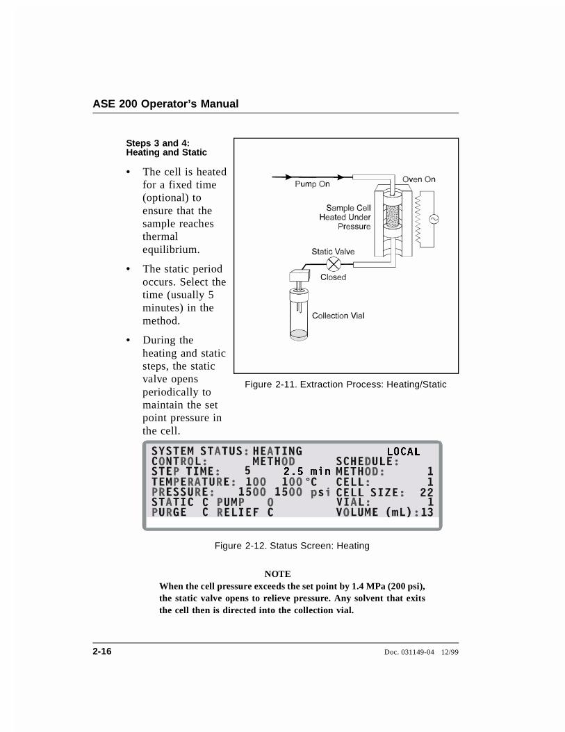
NOTEWhen the cell pressure exceeds the set point by 1.4 MPa (200 psi),the static valve opens to relieve pressure. Any solvent that exitsthe cell then is directed into the collection vial.
Steps 3 and 4: Heating and Static
• The cell is heatedfor a fixed time(optional) toensure that thesample reachesthermalequilibrium.
• The static periodoccurs. Select thetime (usually 5minutes) in themethod.
• During theheating and staticsteps, the staticvalve opensperiodically tomaintain the setpoint pressure inthe cell.
Figure 2-11. Extraction Process: Heating/Static
PLQ���
°
/2&$/
Figure 2-12. Status Screen: Heating
ASE 200 Operator’s Manual
2-16 Doc. 031149-04 12/99
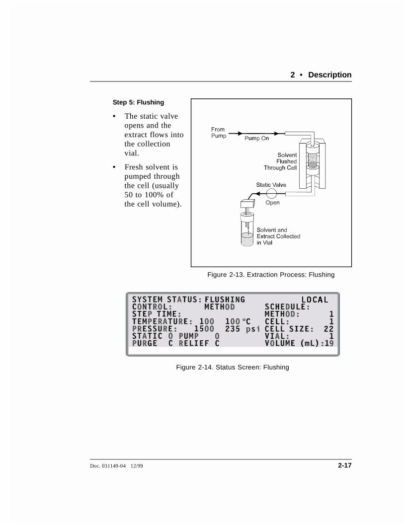
Step 5: Flushing
• The static valveopens and theextract flows intothe collection vial.
• Fresh solvent ispumped throughthe cell (usually50 to 100% of the cell volume).
Figure 2-13. Extraction Process: Flushing
°
/2&$/
Figure 2-14. Status Screen: Flushing
2 • Description
Doc. 031149-04 12/99 2-17
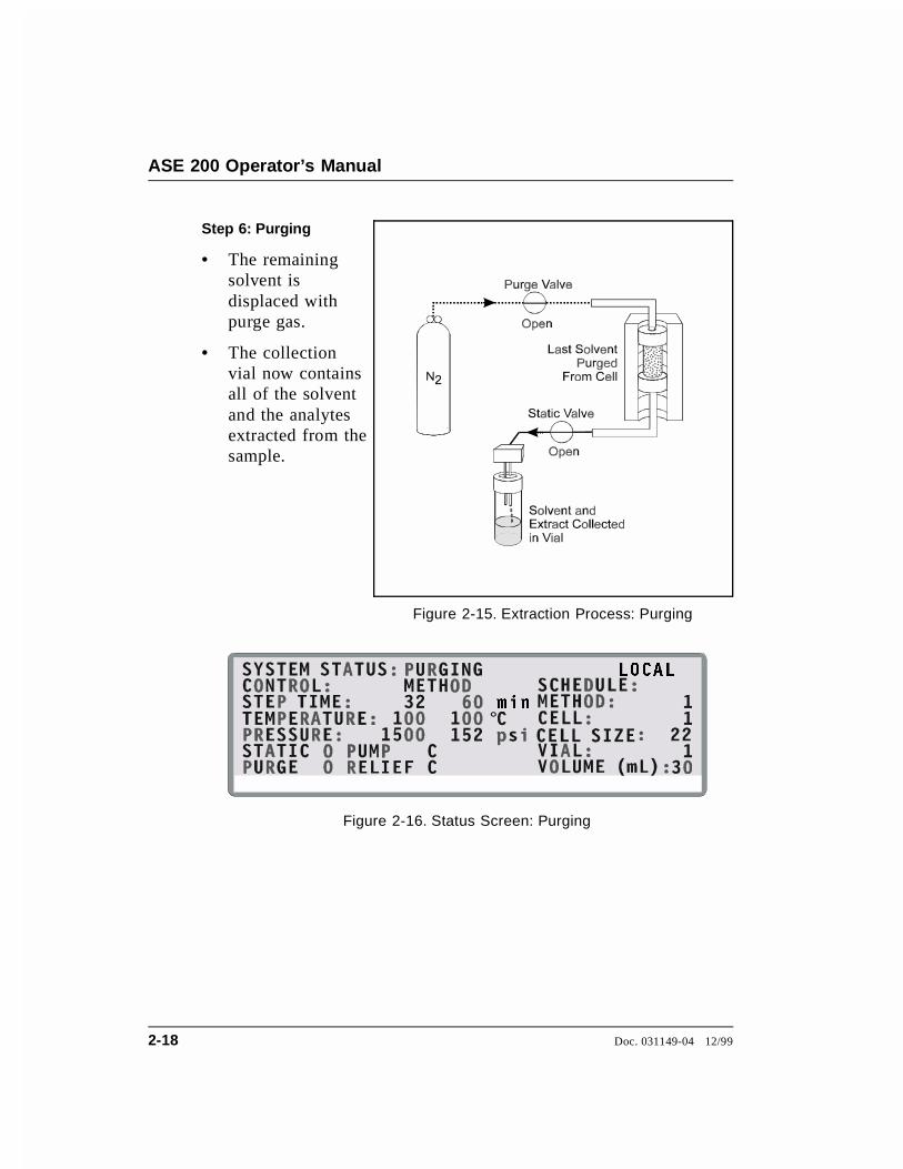
Step 6: Purging
• The remainingsolvent isdisplaced withpurge gas.
• The collectionvial now containsall of the solventand the analytesextracted from thesample.
Figure 2-15. Extraction Process: Purging
°
/2&$/
PLQ
Figure 2-16. Status Screen: Purging
ASE 200 Operator’s Manual
2-18 Doc. 031149-04 12/99

5HVLGXDO 3UHVVXUH
5HOHDVHG IURP &HOO
3UHVVXUH 5HOLHI 9DOYH
6ROYHQW DQG ([WUDFW
&ROOHFWHG LQ 9LDO
6WDWLF 9DOYH
2SHQ
2SHQ
Figure 2-17. Extraction Process: End Relief
(1' 5(/,() /2&$/
°
Figure 2-18. Status Screen: End Relief
Step 7: End Relief
• Residual pressureis released fromthe extraction cell.
2 • Description
Doc. 031149-04 12/99 2-19
Cells are extremely hot after an extraction. Allow the cellsto cool for at least 15 minutes before handling, especiallyif the cells were heated over 50 °C.
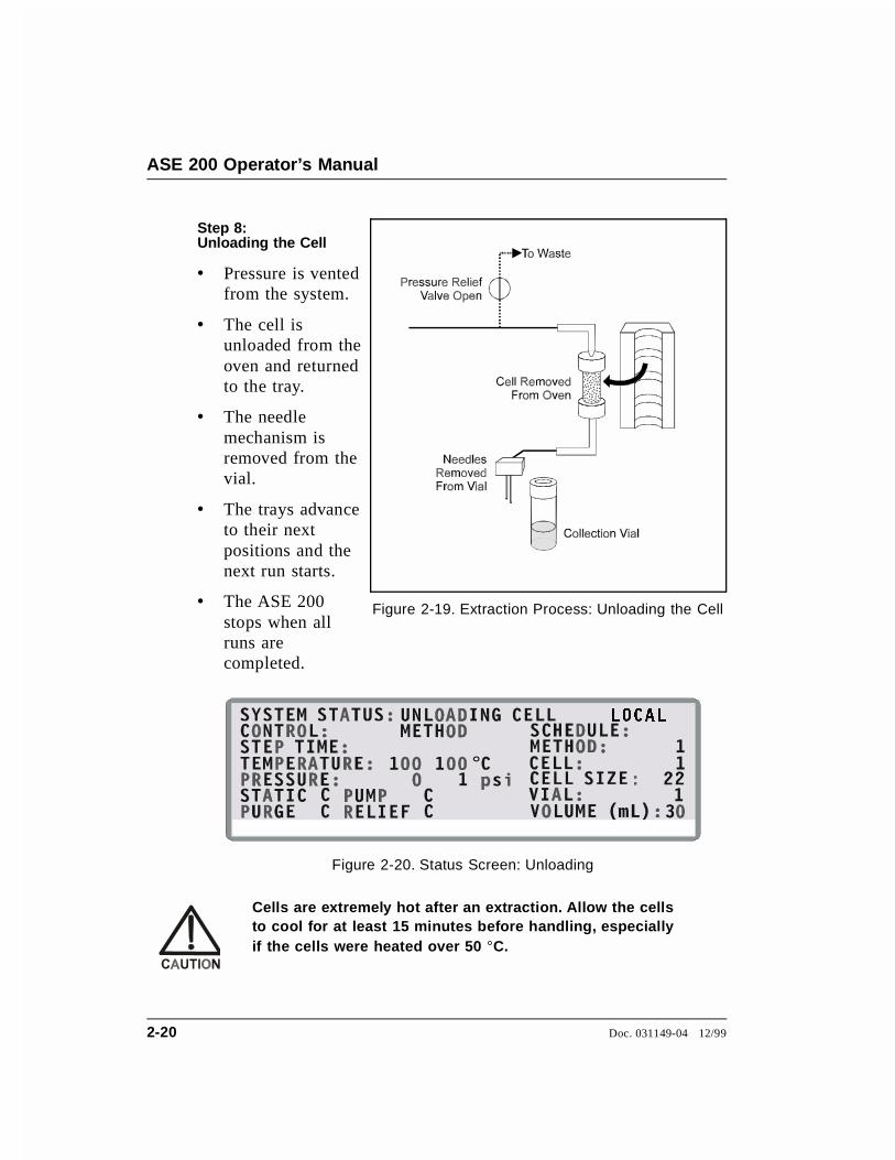
Step 8: Unloading the Cell
• Pressure is ventedfrom the system.
• The cell isunloaded from theoven and returnedto the tray.
• The needlemechanism isremoved from thevial.
• The trays advanceto their nextpositions and thenext run starts.
• The ASE 200stops when allruns arecompleted.
Figure 2-19. Extraction Process: Unloading the Cell
°
/2&$/
Figure 2-20. Status Screen: Unloading
ASE 200 Operator’s Manual
2-20 Doc. 031149-04 12/99

During an extraction, solenoids turn the pump flow on and off. Inaddition, the following valves control solvent flow and pressure inthe system:
• The static valve controls the flow of solvent to the collectionvial. Pressure in the cell increases when the pump is on and thestatic valve is closed.
• The purge valve controls gas pressure to the cell.
• The pressure relief valve releases any residual pressure after anextraction.
• The prime valve controls gas pressure to the solvent bottle.
Figure 2-21 illustrates the positions of the valves at each step of theextraction process.
EN D RELIEF
HEAT/STATIC
LO AD/UNLOAD PU RGE
FILL
FLUSH RINSE
IDLE
Figure 2-21. Valve Positions During Extraction Process
2 • Description
Doc. 031149-04 12/99 2-21

2.3 Operating Modes
The ASE 200 has two operating modes: Local and Remote. Selectthe mode from the MODULE SETUP screen (see Section B.3).
2.3.1 Local Mode
When the ASE 200 power is turned on, it defaults to Localmode. In Local mode, operation is controlled by commandsinput directly from the ASE 200 keypad.
2.3.2 Remote Mode
In Remote mode, the ASE 200 accepts operating commandsfrom AutoASE software via the DX-LAN interface. WhenRemote mode is selected, the word REMOTE appears in theupper right corner of the CURRENT STATUS screen and thescreen displays the method steps as they are executed.
In Remote mode, the following conditions apply:
• Only three ASE 200 keypad buttons are functional: Trays,Rinse, and Abort.
• The LOAD METHOD OR SCHEDULE screen is not accessible.Although other screens can be displayed, only one fieldcan be edited: the operating mode can be toggled fromRemote to Local on the MODULE SETUP screen.
• All global print or rinse commands selected from thekeypad are disregarded.
Sending an operating command from AutoASE automaticallyswitches the ASE 200 to Remote mode, if it is not alreadyselected. However, AutoASE cannot reset the mode to LOCAL.
To return to LOCAL mode after running AutoASE, open theMODULE SETUP screen and reset the mode.
ASE 200 Operator’s Manual
2-22 Doc. 031149-04 12/99

2.4 Method and Schedule Control
NOTEThis section describes how to create methods and schedules fromthe ASE 200 front panel. For instructions on creating methodsand schedules from AutoASE software, refer to the AutoASEmanual.
Before running an extraction, you must create a method that definesoperating conditions for the run. A method specifies the followingparameters:
• Cell heating time
• Oven temperature
• Cell pressure
• Amount of solvent to flush through the cell
• Solvent types and percentages (only when the ASE 200 SolventController is installed)
• Purge time
The ASE 200 can store up to 24 methods. Section 3.2.1 describeshow to create methods from the ASE 200 front panel.
For a series of extractions, you can define a schedule of runs. Aschedule specifies the method to run on each sample in the schedule,the sample cell assigned to each collection vial, and the rinse statusafter each sample run. The ASE 200 can store up to 24 schedules.Section 3.2.3 describes how to create schedules from the ASE 200front panel.
The ASE 200 provides two control modes:
• Method control runs the same method on each consecutivesample loaded in the tray.
• Schedule control runs a series of methods according to theschedule definition.
2 • Description
Doc. 031149-04 12/99 2-23

ASE 200 Operator’s Manual
2-24 Doc. 031149-04 12/99

3 • Operation and Maintenance
3.1 Preparing to Run
3.1.1 Solvent Selection and Preparation
When developing a new extraction method, select a solvent orsolvent mixture that has a high solubility for the analytes ofinterest, but not for the sample matrix. If you have been usinganother extraction method (Soxhlet, for example), continueusing the same solvent with the ASE 200.
Do not use solvents with an autoignition point of 40 to200 °C. The table below lists some solvents that should notbe used with the ASE 200. If you have a question aboutsolvent suitability, contact Dionex.
Solvents Not to Use Autoignition Point
Carbon disulfide CS2 100 °CDiethylether (C2H5)2O 180 °C1,4-Dioxane C4H8O2 180 °C
Follow these guidelines when selecting and preparingsolvents:
• Use HPLC- or pesticide-grade solvents.
• Use organic or aqueous solvents.
• Use single- or multiple-component solvents.
Doc. 031149-04 12/99 3-1

• Weak acids and bases (for example, acetic acid andpotassium hydroxide) or other noncorrosive additives maybe used, but should be added in small percentages (<5%by volume) to the solvent system.
NOTEAfter extracting with acidic solvents or basic solvents,rinse the system with 100% organic solvent or withdistilled water before overnight shutdown.
• Solvents do not generally need to be degassed. Degassolvents only if the analyte of interest oxidizes easily.
• If the extraction cell cap external O-ring is Viton, do notuse acetone.
3.1.2 Filling the Solvent Reservoir
NOTEWhen using an ASE 200 Solvent Controller, disregardthis section and follow the instructions in the SolventController manual.
1. Fill the solvent reservoir with prepared solvent and set itinside the ASE 200 solvent reservoir compartment (seeFigure 2-1).
Use only Dionex solvent reservoirs (1-liter, P/N 045900;2-liter, P/N 045901). These are glass reservoirs with a plastic,shatterproof coating. Make sure the pressure applied tothe reservoirs does not exceed 0.07 MPa (10 psi).
2. Insert the outlet line extending from the underside of thereservoir cap assembly into the reservoir (see Figure 3-1).Make sure that the in-line filter rests on the bottom of thereservoir. This prevents air from being drawn through theline. If needed, gently pull on the outlet line to bringmore tubing into the reservoir.
ASE 200 Operator’s Manual
3-2 Doc. 031149-04 12/99

3. Make sure that the solvent level in the reservoir is belowthe gas inlet line (see Figure 3-1). This prevents solventfrom coming into contact with pneumatic valves.
4. Hand-tighten the lock ring cap securely over the stopper.
5. When refilling the reservoir, remove the cap and stopperand remove the reservoir from the compartment. It is notnecessary to disconnect the inlet and outlet lines.
Figure 3-1. Solvent Reservoir Connections
3 • Operation and Maintenance
Doc. 031149-04 12/99 3-3

3.1.3 Sample Preparation
Some samples must be mixed with a drying or dispersingagent before being loaded into the cells. If you havesuccessfully followed a particular sample pretreatmentprocedure for another extraction method, continue using thisprocedure. However, if you are preparing a new sample orhave never run an extraction, follow the guidelines below.
Drying or Dispersing Agent Selection Guidelines
• Two drying and dispersing agents are referred to in thesection that follows: sodium sulfate (Na2SO4) andpelletized diatomaceous earth (DE). Of these, DE is easierto work with because it dries samples more quickly,provides a cleaner transfer of the mixtures to the cell, andextracts well. Although sodium sulfate is more readilyavailable, it tends to clump the samples, making transfermore difficult.
• The use of sodium sulfate with very wet samples (30%moisture) can result in clogging of the frits in the cellwith recrystallized sodium sulfate, particularly if a mixedsolvent with acetone is used. In these cases, use DE as adrying agent and mix it with the sample before loadinginto the extraction cell. (Alternately, DE can be used as adrying agent in the cell in place of sodium sulfate for alllevels of moisture.)
• For very wet samples, regardless of which drying agent isused, you must add sodium sulfate to the vials aftercollection and then pass the extracts through a dryingcolumn or drying cartridge to dry the extract completely.At the temperatures used during ASE 200 extractions,more water is co-extracted than with other extractionprocedures. To ensure good analyte recovery, thoroughlyrinse the sodium sulfate from the vial and cleanup column.
• Never use sodium sulfate with polar extraction solvents,such as methanol. At the temperatures used during
ASE 200 Operator’s Manual
3-4 Doc. 031149-04 12/99

ASE 200 extractions, polar solvents are dissolved bysodium sulfate.
Sample Preparation Guidelines
The following mixtures are recommendations only; adjust theproportions as required.
• If the sample appears dry, use one of these mixtures:
4 grams sample to 1 gram DE
4 grams sample to 4 grams Na2SO4
• If the sample appears wet, use one of these mixtures:
4 grams sample to 2 grams DE
4 grams sample to 8 grams Na2SO4
• If the sample is pure liquid, use 5 grams sample to 3grams DE
Mix the sample and the DE or Na2SO4 thoroughly in a smallvial, beaker, or mortar.
3 • Operation and Maintenance
Doc. 031149-04 12/99 3-5

3.1.4 Cell Selection and Filling
Five cell sizes are available: 1 mL, 5 mL, 11 mL, 22 mL, and33 mL. The cell size does not affect the extraction time, but itdoes determine how much solvent is used; because the cell isfilled with solvent during the extraction, larger cells requiremore solvent. In addition, a cell that is partially filled withsample requires more solvent than a full cell.
In general, when choosing a cell size:
• Select the smallest cell that holds enough sample toproduce accurate extraction results.
• Take into account any drying or dispersing agents,because these increase the volume of the sample.
• When preparing the sample, make sure that the drying ordispersing agent and sample are thoroughly mixed.
Cell Filters
A disposable filter is installed in the cell before sample isloaded. The filter prevents blockage of the stainless steel fritin the bottom cap. Cellulose filters are available for all cellsizes. In addition, glass-fiber filters are available for 11 mL,22 mL, and 33 mL cells.
Glass-fiber filters are typically used for aqueous extractions,where cellulose may provide inadequate filtration or may be asource of interference with the analytical technique.
Installation of the filters requires a special tool. The tool forthe 11 mL, 22 mL, and 33 mL cells is included in the ASE200 Ship Kit. The other tools must be ordered separately. Usethe same tool for both cellulose and glass-fiber filters.
Cell Size Filter Insertion Tool
1 mL P/N 0553965 mL P/N 05539711 mL, 22 mL, 33 mL P/N 049495
ASE 200 Operator’s Manual
3-6 Doc. 031149-04 12/99
To insert the filter:
Always hand-tighten the bottom cell cap onto the cell bodybefore installing the filter. Do not place the filter in thebottom cap before installing the cap; this creates animproper seal and allows leaks.
NOTEIt may be helpful to use the Dionex logo and serial numberetched on the cell body to identify the direction of fluidflow. For example, designate the end closer to the logo andserial number as the top, and then follow that conventionwhen installing the filter and loading cells into the tray. Ifyou prefer, use a marking pen to draw an arrow on the cellto indicate the direction of flow.
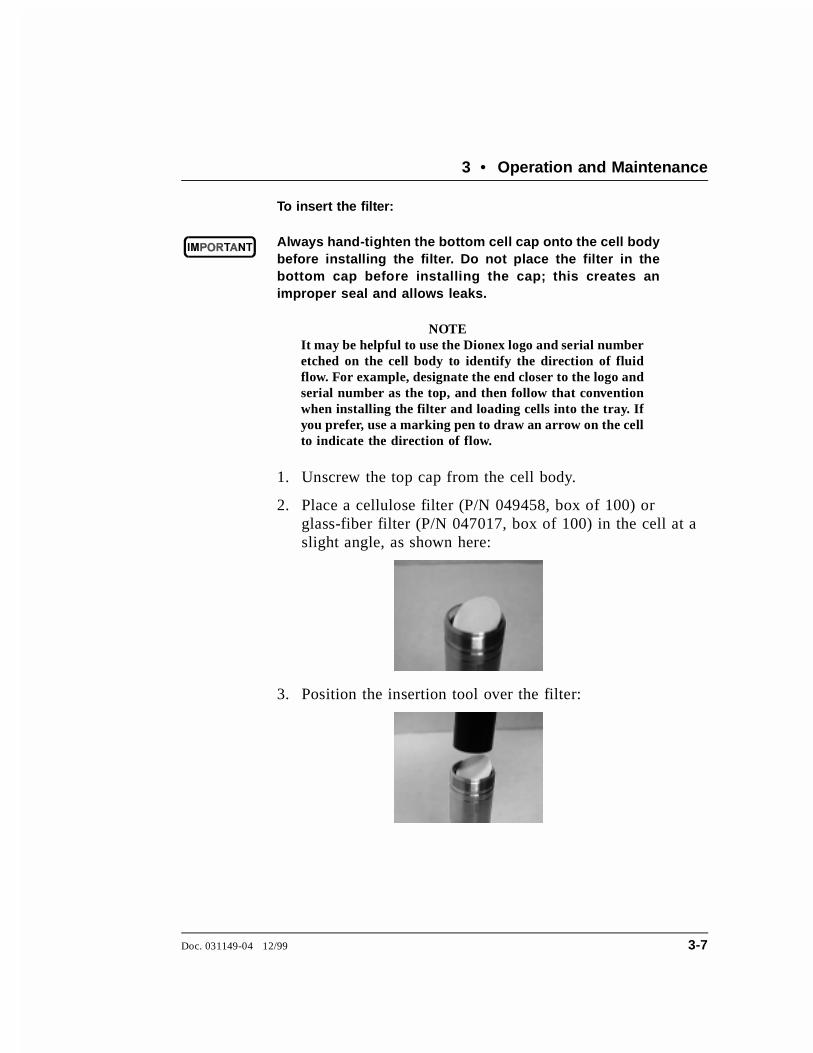
1. Unscrew the top cap from the cell body.
2. Place a cellulose filter (P/N 049458, box of 100) orglass-fiber filter (P/N 047017, box of 100) in the cell at aslight angle, as shown here:
3. Position the insertion tool over the filter:
3 • Operation and Maintenance
Doc. 031149-04 12/99 3-7
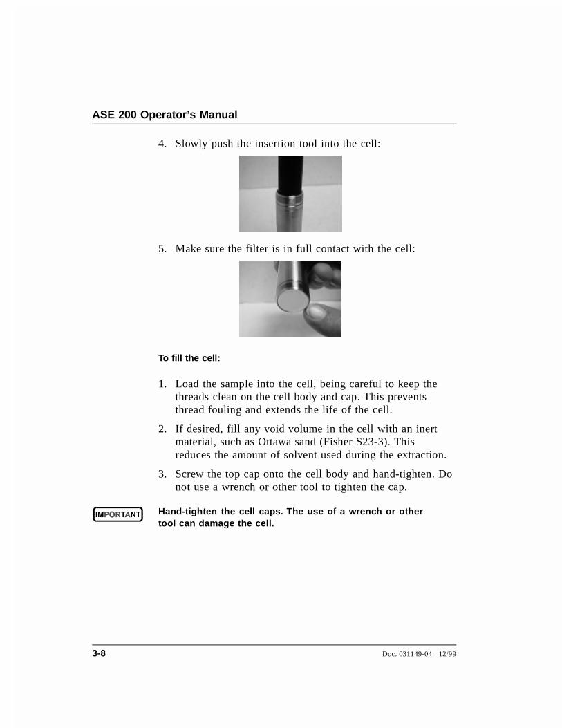
4. Slowly push the insertion tool into the cell:
5. Make sure the filter is in full contact with the cell:
To fill the cell:
1. Load the sample into the cell, being careful to keep thethreads clean on the cell body and cap. This preventsthread fouling and extends the life of the cell.
2. If desired, fill any void volume in the cell with an inertmaterial, such as Ottawa sand (Fisher S23-3). Thisreduces the amount of solvent used during the extraction.
3. Screw the top cap onto the cell body and hand-tighten. Donot use a wrench or other tool to tighten the cap.
Hand-tighten the cell caps. The use of a wrench or othertool can damage the cell.
ASE 200 Operator’s Manual
3-8 Doc. 031149-04 12/99

4. Check the end of each cap to verify that the white O-ringsare in place and in good condition (see Figure 3-2). If anO-ring is discolored or has a hole size of less than0.5 mm, replace it.
Remove worn O-rings with a small flathead screwdriver.Place the new O-ring over the opening in the end of thecell cap and press it into place, using the tool(P/N 049660) provided in the Ship Kit.
Do not attach any labels to the cell. The cells fit snugly inthe oven during the extraction process and a label maycause misalignment. In addition, the high temperaturesused during extraction can damage the label. For sampleidentification, reference the Dionex serial number etchedon the cell or write on the cell body with a marking pen.
Check ends of cells andrinse tubes for white O-rings(Teflon: P /N 049457, Pkg. 50;Viton: P /N 056325, Pkg. 50)
CellR inse Tube
Figure 3-2. O-Ring Inspection
3 • Operation and Maintenance
Doc. 031149-04 12/99 3-9
To load the cell tray:
1. Begin loading filled cells into the tray slots in numericalorder. Hang the cells vertically in the tray slots from theirtop caps (the bottom cap contains the cellulose filter). Thecells can be mixed on the tray in any order.
In its default control mode (method mode), the ASE 200begins running at cell 1 and vial 1 and continues untilcompleting the entire tray (if it is full) or until reachingan empty vial or cell slot. An empty slot indicates the endof the run and the ASE 200 stops. For greater flexibility,create a schedule of runs. Section 3.2 describes methodand schedule modes in detail.
To avoid injury, exercise caution when the tray is in motion.
2. Check the end of each rinse tube to verify that theO-rings are in place and in good condition (seeFigure 3-2). If an O-ring is discolored or has a hole sizeof less than 0.5 mm, replace it.
Remove worn O-rings with a small flathead screwdriver.Place the new O-ring over the opening in the end of thecell cap and press it into place, using the tool(P/N 049494) provided in the Ship Kit.
3. Load the rinse tubes into the four open slots between cellpositions 1 and 24, 6 and 7, 12 and 13, and 18 and 19.
ASE 200 Operator’s Manual
3-10 Doc. 031149-04 12/99

3.1.5 Vial Selection and Loading
Select the vial size according to the size of the cell:
• For 1 mL cells, use 40 mL vials
• For 5 mL cells, use 40 mL vials
• For 11 mL cells, use 40 mL vials
• For 22 mL cells, use 60 mL vials
• For 33 mL cells, use 60 mL vials
Vial Labeling
During the extraction process, sensors determine if a vial ispresent, contains 1 mL of solvent, or is full. Therefore, viallabels must be placed so that they do not block areas of thevial read by the sensors. Figure 3-3 shows where to attach alabel, or to write an identification name or number, so thatthe identification does not block the sensors.
To remove the vial tray:
Remove the vial tray only when the ASE 200 is idle. (TheLED on the left of the Start button is lighted when theASE 200 is idle.)
Grasp the center handle and lift straight up to clear the trayfrom its support base. Remove the tray from the instrument.
To reinstall the vial tray:
Center the tray over the support base until it slips into placeon the support platter.
(Optional) Turn the tray manually (in either direction) untilyou hear a click, indicating that the tray is locked into thecorrect position.
3 • Operation and Maintenance
Doc. 031149-04 12/99 3-11

Figure 3-3. Acceptable Vial Label Locations (Vials shown actual size)
ASE 200 Operator’s Manual
3-12 Doc. 031149-04 12/99

To load the vials:
Follow these guidelines when loading vials into the tray:
• When using the regular 40 mL vials, place tray inserts(P/N 049348) into the vial tray slots to adapt them for theshorter vials. When using graduated 40 mL vials, placevial spacers (P/N 055444) into the vial tray slots. The60 mL vials do not require either inserts or spacers.
• When running under method control, for each sample cellloaded, load a collection vial into the corresponding vialtray position. For example, if positions 1 through 10contain sample cells, load vials in positions 1 through 10.
• When running under schedule control, load the vials asprogrammed in the schedule. (See Section 3.2 for adescription of method and schedule modes.)
• When mixing cell sizes, be sure to match the collectionvial size to the cell size.
1. Load four vials (40 mL or 60 mL) into the rinse slots(labeled R1 through R4). If available, use the 60 mLvials, to increase the rinse collection capacity.
Check rinse vials after each series of runs, and empty ifneeded before starting the next series.
2. Check that all loaded vials are at a uniform height andthat the caps extend above the tray slots. If necessary,remove or add tray inserts or spacers.
3. Make sure the vial sizes match the size of the loadedsample cells (see Section 3.1.5).
If the vial and cell sizes are mismatched, the sample willabort.
3 • Operation and Maintenance
Doc. 031149-04 12/99 3-13

3.1.6 Rinsing/Priming the System
Pressing the Rinse button on the keypad starts a manual rinse,or prime, cycle. During the cycle, the cell tray rotates to thenearest rinse tube, the vial tray rotates to a rinse position, andapproximately 4 mL of solvent is pumped through the system.
Run a rinse cycle at the following times:
• After initial setup
NOTEWhen running with an ASE Solvent Controller, thesystem automatically rinses with 8 mL of solvent whenthe Start button is pressed. The rinse is also 8 mL ifthe schedule calls for a change of solvent.
• After the ASE 200 has been shut down for more than aday, or when there are bubbles in the solvent lines
• After refilling the solvent reservoir
• After changing solvents (rinse twice to remove all of theold solvent)
To set up the ASE 200 to automatically run a rinse betweensample extractions, see Section 3.1.7.
ASE 200 Operator’s Manual
3-14 Doc. 031149-04 12/99
3.1.7 Automatic Rinsing Between Samples
An automatic rinse cycle can run between sample extractions.The automatic rinse cycle is identical to the manual rinsecycle (see Section 3.1.6), except that only 1 mL of solvent ispumped through the system during an automatic rinse cycle.
• When running under method control, you can set up theASE 200 to run an automatic rinse cycle after eachsample extraction (see the steps below).
• When running under schedule control, you must specifyon each line in the schedule whether an automatic rinsecycle is performed (see Section 3.2.3).
To set up automatic rinses during method control:
1. Verify that rinse tubes and vials are in place and that thevials are empty. Use 60 mL vials, if available, becausethey provide more rinse collection capacity.
2. Press Menu to display the MENU OF SCREENS and press 5to display the MODULE SETUP screen.
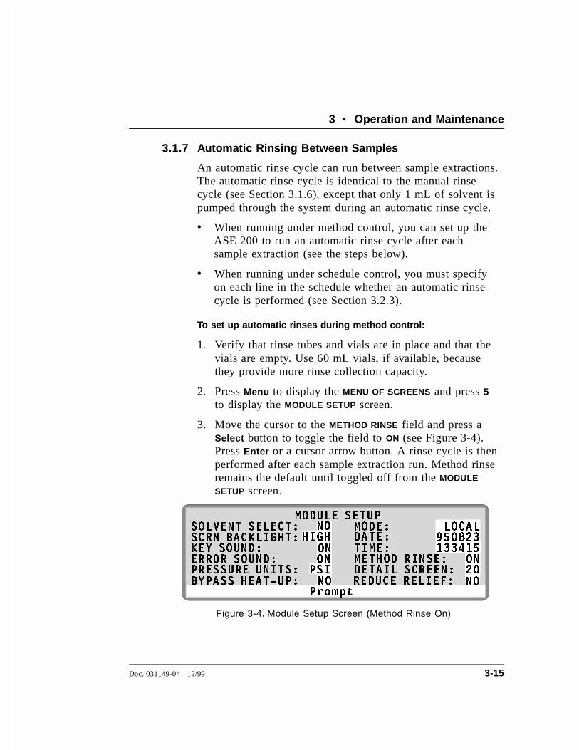
3. Move the cursor to the METHOD RINSE field and press aSelect button to toggle the field to ON (see Figure 3-4).Press Enter or a cursor arrow button. A rinse cycle is thenperformed after each sample extraction run. Method rinseremains the default until toggled off from the MODULE
SETUP screen.
3URPSW
02'8/( 6(783
+,*+2121
36,
6&51 %$&./,*+7�.(< 6281'�(5525 6281'�35(6685( 81,76�
'$7(�7,0(�0(7+2' 5,16(�'(7$,/ 6&5((1�
������21��
������62/9(17 6(/(&7� 02'(�
21
12 /2&$/
%<3$66 +($7�83� 5('8&( 5(/,()�12 12
Figure 3-4. Module Setup Screen (Method Rinse On)
3 • Operation and Maintenance
Doc. 031149-04 12/99 3-15

3.1.8 Operation with an External Device
An external sample preparation device (such as a deviceequipped with a robotic arm) can be interfaced to the ASE200 to perform these tasks:
• Access collection vials containing sample processed bythe ASE 200, or
• Insert cells into the ASE 200 cell tray and/or remove cellsfrom the cell tray
When interfaced with an external device, the ASE 200 canoperate in one of two modes:
• In the fixed time mode, operation is based on a specifiedtime period.
• In the TTL mode, operation is based on synchronizationof TTL start and stop signals.
For more information about these operating modes, refer tothe following sections.
External Device Operation: Fixed Time Mode
To operate in the fixed time mode, the user must specify thevial tray and/or cell tray position and the length of time eachtray remains immobile. While the trays are immobile, theexternal device accesses the sample cells and/or extractionvials. At the end of the specified time, the ASE 200 goes onto perform the next extraction in the entered method orschedule.
ASE 200 Operator’s Manual
3-16 Doc. 031149-04 12/99
Specify the operating conditions:
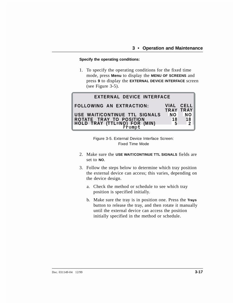
1. To specify the operating conditions for the fixed timemode, press Menu to display the MENU OF SCREENS andpress 9 to display the EXTERNAL DEVICE INTERFACE screen(see Figure 3-5).
2. Make sure the USE WAIT/CONTINUE TTL SIGNALS fields areset to NO.
3. Follow the steps below to determine which tray positionthe external device can access; this varies, depending onthe device design.
a. Check the method or schedule to see which trayposition is specified initially.
b. Make sure the tray is in position one. Press the Trays
button to release the tray, and then rotate it manuallyuntil the external device can access the positioninitially specified in the method or schedule.
EXTERNAL DEVICE INTERFACE
FOLLOW ING AN EXTRACTION:
USE WAIT/CONTINUE TTL SIGNALSROTATE TRAY TO POSITIONHOLD TRAY (TTL=NO) FOR (M IN)
NO NO
VIAL CELLTRAYTRAY
18 185 2
Figure 3-5. External Device Interface Screen: Fixed Time Mode
3 • Operation and Maintenance
Doc. 031149-04 12/99 3-17
c. Check to see which tray position is now in the homeposition. Move the cursor to the ROTATE TRAY TO
POSITION field for the tray(s) to be accessed by theexternal device and enter this number. Press Enter or acursor arrow button.
NOTEDo not enter vial tray positions 1 through 7 or 20through 24; the ASE 200 enclosure blocks access tothese positions.
NOTEThe ASE 200 automatically increments the trayposition with each extraction. For example, if youselect tray position 26 to make vial 10 accessible forextraction 1, the ASE 200 will automatically move tovial 11 for extraction 2.
4. Move the cursor to the HOLD TRAY FOR field and enter thenumber of minutes that the tray remains immobile. Besure to allow enough time for the external device toperform its function and then move clear of the traysbefore the ASE 200 goes on to the next extraction. PressEnter or a cursor arrow button.
If the specified time is too short, the ASE 200 may attemptto move a tray while it is being accessed by the externaldevice.
5. This completes the setup for operation in the fixed timemode.
ASE 200 Operator’s Manual
3-18 Doc. 031149-04 12/99

External Device Operation: TTL Mode
In the TTL mode, wait/continue TTL signals are used tocontrol rotation of the vial tray and/or cell tray. After eachextraction, the ASE 200 sends a TTL output signal to theexternal device and then waits for the device to send a TTLsignal. When the ASE 200 receives the TTL signal sent bythe device, it goes on to the next extraction in the method orschedule.
Specify the operating conditions:
1. To specify the operating conditions for the TTL mode,press Menu to display the MENU OF SCREENS and press 9to display the EXTERNAL DEVICE INTERFACE screen (seeFigure 3-6).
2. Move the cursor to the USE WAIT/CONTINUE TTL SIGNALS
field for the tray(s) to be accessed by the external deviceand select YES. Press Enter or a cursor arrow button.
3. Follow the steps below to determine which tray positionthe external device can access; this varies, depending onthe device design.
a. Check the method or schedule to see which trayposition is specified initially.
EXTERNAL DEVICE INTERFACE
FOLLOW ING AN EXTRACTION:
USE WAIT/CONTINUE TTL SIGNALSROTATE TRAY TO POSITIONHOLD TRAY (TTL=NO) FOR (M IN)
YESYES
VIAL CELLTRAYTRAY
18 18 0 0
Figure 3-6. External Device Interface Screen: TTL Mode
3 • Operation and Maintenance
Doc. 031149-04 12/99 3-19
b. Make sure the tray is in position one. Press the Trays
button to release the tray, and then rotate it manuallyuntil the external device can access the positioninitially specified in the method or schedule.
c. Check to see which tray position is now in the homeposition. Move the cursor to the ROTATE TRAY TO
POSITION field for the tray(s) to be accessed by theexternal device and enter this number. (Do not enterzero, which disables operation of the external deviceinterface feature.) Press Enter or a cursor arrow button.
NOTEDo not enter vial tray positions 1 through 7 or 20through 24; the ASE 200 enclosure blocks access tothese positions.
NOTEThe ASE 200 automatically increments the trayposition with each extraction. For example, if youselect tray position 26 to make vial 10 accessible forextraction 1, the ASE 200 will automatically move tovial 11 for extraction 2.
4. Make sure zero is entered in the HOLD TRAY FOR fields, todisable operation in the fixed time mode. Go on to thenext section to make the TTL connections.
Make the TTL connections:
1. The TTL/relay connector strip is located on the CPU card,behind the upper door (see Figure B-15). To open thedoor, pull on the tab located to the right of the mainpower actuator (see Figure 2-2).
Each 2-pin connector on the strip includes a signal pin (+)and a ground (-) pin. The ASE 200 Ship Kit includestwisted pairs of wires (P/N 043598) and eight 2-pinconnector plugs (P/N 921019).
ASE 200 Operator’s Manual
3-20 Doc. 031149-04 12/99

2. Attach a 2-pin connector plug to both ends of each pair ofwires to be connected. Strip the ends of the wires, insertinto the plug, and use a screwdriver to tighten the lockingscrew. The signal wire goes on the top of each plug; theground wire goes on the bottom of the plug.
3. Connect these plugs to the TTL connectors on the ASE200 and the external device as needed. Route the wiresthrough the service chase to the external device (seeFigures B-15 and B-16). (Check the external device user’smanual for connector details.)
TTL input 1 controls movement of the collection vial trayand TTL input 2 controls movement of the cell tray.Figure 3-7 shows the setup required for the externaldevice to access both trays.
4. Check the polarity of each connection. Be sure to connectsignal wires to signal (+) pins and ground wires to ground(-) pins (see Figure 3-7).
TT
L 1
OU
T
TT
L 2
IN
TT
L 2
OU
T
TT
L 1
IN
GN
D
GN
D
GN
D
GN
D
RLY-1OUT
RLY-2OUT
T+-
+-
+-
+-
+-
+-
TL-1OUT
TTL-2OUT
TTL-1IN
TTL-2IN
TTL-3IN
TTL-4IN
EXTERNAL DEVICE
ASE 200
*Inactive
Vial Tray
Vial Tray
Cell Tray
Cell Tray
Figure 3-7. TTL Connections to an External Device
3 • Operation and Maintenance
Doc. 031149-04 12/99 3-21
5. If necessary, remove wires from the 2-pin plugs andreinsert them in the correct positions. To remove the plugsfrom the connector strip, pull them straight out.
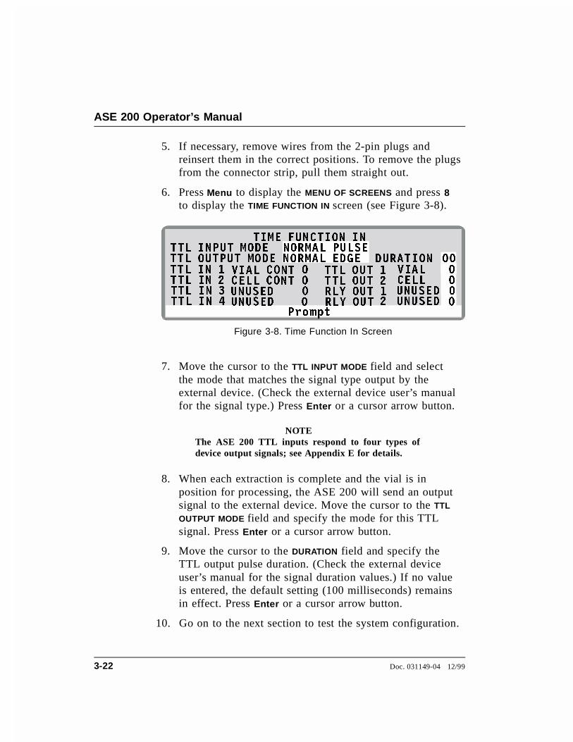
6. Press Menu to display the MENU OF SCREENS and press 8to display the TIME FUNCTION IN screen (see Figure 3-8).
7. Move the cursor to the TTL INPUT MODE field and selectthe mode that matches the signal type output by theexternal device. (Check the external device user’s manualfor the signal type.) Press Enter or a cursor arrow button.
NOTEThe ASE 200 TTL inputs respond to four types ofdevice output signals; see Appendix E for details.
8. When each extraction is complete and the vial is inposition for processing, the ASE 200 will send an outputsignal to the external device. Move the cursor to the TTL
OUTPUT MODE field and specify the mode for this TTLsignal. Press Enter or a cursor arrow button.
9. Move the cursor to the DURATION field and specify theTTL output pulse duration. (Check the external deviceuser’s manual for the signal duration values.) If no valueis entered, the default setting (100 milliseconds) remainsin effect. Press Enter or a cursor arrow button.
10. Go on to the next section to test the system configuration.
3URPSW
7,0( )81&7,21 ,1
9,$/ &217 9,$/&(// &217 &(//8186(' 8186('8186(' 8186('
��� �
� �� �
� �
'85$7,2177/ ,1387 02'(
77/ ,1 � 77/ 287 �77/ ,1 � 77/ 287 �
�77/ ,1 � 5/< 287 �77/ ,1 � 5/< 287
77/ 287387 02'(1250$/ 38/6(1250$/ ('*(
Figure 3-8. Time Function In Screen
ASE 200 Operator’s Manual
3-22 Doc. 031149-04 12/99

Test the system configuration:
1. Press Menu to display the MENU OF SCREENS and press 8to display the TIME FUNCTION IN screen.
2. To verify the setup for the collection vial tray, move thecursor to the TTL OUT 1 VIAL field on the TIME FUNCTION IN
screen (see Figure 3-9). Select 1 and then press Enter or acursor arrow button. The external device should respondwhen it receives the TTL signal.
3. To verify the setup for the cell tray, move the cursor tothe TTL OUT 2 CELL field on the TIME FUNCTION IN screen(see Figure 3-9). Select 1 and then press Enter or a cursorarrow button. The external device should respond when itreceives the TTL signal.
4. If the external device fails to respond to a TTL signal, dothe following:
Check that the TTL connections are correctly made.
Check that the correct TTL input mode is selected.
Using a digital voltmeter, verify that the ASE 200 issending a +5 V signal.
5. This completes the setup for operation in the fixed timemode.
3URPSW
7,0( )81&7,21 ,1
9,$/ &217 9,$/&(// &217 &(//8186(' 8186('8186(' 8186('
��� �
� �� �
� �
'85$7,2177/ ,1387 02'(
77/ ,1 � 77/ 287 �77/ ,1 � 77/ 287 �
�77/ ,1 � 5/< 287 �77/ ,1 � 5/< 287
77/ 287387 02'(1250$/ 38/6(1250$/ ('*(
Figure 3-9. Time Function In Screen: TestingTTL Mode
3 • Operation and Maintenance
Doc. 031149-04 12/99 3-23

3.2 Methods and Schedules
NOTEThe following sections describe how to create custom methodsand schedules from the ASE 200 front panel. To get startedquickly, without creating a new method, run the default method(see Section 3.4.1). For instructions on how to use AutoASEsoftware to create methods and schedules, refer to the AutoASEmanual.
Each sample extraction occurs according to a predefined set ofoperating parameters, or method. A method specifies the cell heatingtime, oven temperature, cell pressure, etc. The ASE 200 can store upto 24 methods.
When running a series of extractions, you can run each sample usingthe same method (method control), or customize the series bydefining a schedule of runs (schedule control). A schedule specifiesthe method to run on each sample in the schedule, the sample cellassigned to each collection vial, and the rinse status after eachsample run. The ASE 200 can store up to 24 schedules.
Table 3-1 summarizes methods and schedules and the control modes:
Feature Description
Method Defines the operating parameters for a single extraction run(oven temperature, time, pressure, amount of solvent flush,purge time, and, if an ASE 200 Solvent Controller is in use,the solvent types and concentrations).
Schedule Defines parameters for a series of extraction runs (cellsequence, method to run on each cell, rinse status).
Method control Runs the same method on each sample loaded in the tray. The series of runs starts with cell position 1 and vial position1 and proceeds sequentially until all samples are extracted.
Schedule control Runs a series of extractions according to the scheduledefinition.
Table 3-1. Methods and Schedules Summary
ASE 200 Operator’s Manual
3-24 Doc. 031149-04 12/99

3.2.1 Creating Methods
Table 3-2 describes each method parameter. Refer toSection 3.2.2 for example methods and Section 3.3 formethod development guidelines.
1. Press Menu to display the MENU OF SCREENS and press 3to display the METHOD EDITOR. If you are opening thescreen for the first time after power-up, the screendisplays the default method parameters (see Figure 3-10).Thereafter, the screen displays the last method that wasedited (if any) or the default parameters (if there is noprevious method).
2. To display the default parameters, verify that the cursor isin the EDIT# field and enter zero.
3. To create a method, move the cursor to each highlightedfield to be changed and enter the desired value. Afterentering a new value, save it by pressing Enter or bypressing a cursor arrow button.
3URPSW
0(7+2' (',7 6$9( 7235(+($7
PLQSVL&
���PLQ%YRO%VHF %
67$7,&)/86+�385*(&<&/(6
35(6685(7(03(5$785(62/ $62/ %62/ &��
���
��
�����
�
�
#
27+(5
27+(527+(5 �
62/ '27+(527+(5 %�
%
�
+($7PLQ &�
Figure 3-10. Method Editor Screen (Default)
3 • Operation and Maintenance
Doc. 031149-04 12/99 3-25

Parameter Function Value Range
PREHEAT Amount of time the cell sits in the oven,being preheated, before solvent is introduced.
0 to 99 min(default=0)
The state of the purge valve during thePREHEAT period. (This unlabeled field is tothe right of the PREHEAT field.)
C=closed,O=open(default=C)
HEAT Amount of time allowed for the sample toreach thermal equilibrium. The duration of theinitial heat-up step depends on the method’stemperature set point.Set the set point to 0 only when the heat-upperiod is not required to achieve completerecovery of analytes.
Set Point (°C) Heat-up Time (Minutes)0 (off) 040-100 5101-125 6126-150 7151-175 8176-200 9
5 to 9 min
STATIC Static solvent extraction time. 0 to 99 min(default=5)
FLUSH% Amount of solvent to flush through the cellfollowing the static heating step, expressed asa percentage of the cell volume. For example,if FLUSH=50%, 0.5 mL is flushed through a1 mL cell, 2.5 mL is flushed through a 5 mL,and so on.
0 to 150% volin 5%increments(default=60)
PURGE Amount of time nitrogen gas purges the cell. 0 to 300 sec(default=60)
CYCLES Number of times to perform the static heatingand flushing steps. When more than one cycleis specified, the flush % volume is dividedamong the cycles (see Example Method 1 onpage 3-30).
1 to 5(default=1)
Table 3-2. Method Editor Parameters
ASE 200 Operator’s Manual
3-26 Doc. 031149-04 12/99

4. After entering the desired parameters, move the cursor tothe SAVE TO field. Enter a new (unused) method number,or press Select ∆ to display the next unused methodnumber. Press Enter to save the method.
NOTETo restore the default method parameters, move thecursor to the EDIT# field and press Delete.
When the cursor is in the SAVE TO field, pressing Select ∆cycles through the available method numbers. Forexample, if methods 1 and 3 already exist, pressingSelect ∆ displays 2, the next unused number. Pressing
Parameter Function Value Range
TEMPERATURE Temperature at which to heat the cell. Thetemperature also determines the duration ofthe initial heat-up step.
0, 40 to200 °C (0=off,default=100)
PRESSURE Amount of fluid pressure in the cell duringextraction. The pressure is maintained by thepump.
500 to 3000psi(default=1500)3.45 to 21MPa(default=10.34)34 to 204 atm(default=102.1)34 to 207 bar(default=103.4)
SOL ASOL BSOL CSOL D
The solvent type and concentration used forthe extraction. Unless an ASE 200 SolventController is in use, this information is forreport purposes only and these fields may beleft blank.
5 to 100% in5% incre-ments(default=100% of solvent A);solvent typesare listed onpage 3-28
Table 3-2. Method Editor Parameters (continued)
3 • Operation and Maintenance
Doc. 031149-04 12/99 3-27
Select ∆ again displays 4, the next unused number. PressEnter to save the method under the desired number.
Entering Solvent Types and Percentages
The METHOD EDITOR screen lists some of the most commonsolvents for extractions. From the list, select the type(s) andpercentage of solvent(s) used in each method. If the solvent isnot listed, select OTHER.
Do not use solvents with an autoignition point of 40 to200 °C. If you have a question about solvent suitability,contact Dionex.
When an ASE 200 Solvent Controller is in operation, theseselections determine the solvent type and amount deliveredby the Solvent Controller to the ASE 200. If the SolventController is not present and configured, this informationappears in the report printout (see Section 3.6), but has noeffect on the extraction.
To select a solvent type:
1. Move the cursor to the SOL A field and press Select ∆ orSelect ∇ to scroll through the list of solvents. Thefollowing solvents are listed:
Acetone Hexane MeCl2 Toluene
Acetonitrile iso-Octane Pet Ether Water
Chloroform iso-Propanol PERC Water/Acid
Ethanol Methanol THF Other
2. After selecting the type, press the right cursor arrow to goto the % field and enter the percent concentration. If youenter 100% in this field, the percentages for the otherthree solvents are reset to zero.
ASE 200 Operator’s Manual
3-28 Doc. 031149-04 12/99

3. If the solvent is a mixture of two or more types, enter theother solvent types and percentages in the SOL B, SOL C,and/or SOL D fields. Make sure the total for all solvents isequal to 100%.
Editing Methods
After creating a method, you can modify it by changingparameter values. Either save the changes to the existingmethod number, or save the altered method to a new methodnumber and preserve the original method.
1. Display the METHOD EDITOR screen. In the EDIT# field,enter the number of the method to be edited (1-24), orpress Select ∆ to scroll through the numbers of previouslystored methods.
To display the default method parameters, enter zero.
2. After selecting the method number, press Enter. Themethod’s defined parameters appear.
3. To change a parameter value, move the cursor to the fieldand enter the new value. This deletes the previous value.Table 3-2 lists the values allowed for each parameter.
4. When changes are complete, move the cursor to the SAVE
TO field. Press Enter to save the changes to the currentmethod number, or select a new method number and pressEnter.
3 • Operation and Maintenance
Doc. 031149-04 12/99 3-29

3.2.2 Example Methods
Example Method 1
Figure 3-11 illustrates the METHOD EDITOR screen forExample 1.
When run, the method proceeds as follows:
• The oven begins heating to 75 °C.
• When the oven reaches the set point, the vial and cell areloaded. A PREHEAT period of 1 minute begins and thepurge valve opens.
• At the end of the PREHEAT period, the pump fills the cellwith solvent. The static valve closes and the pumpcontinues pumping until the pressure reaches 1500 psi.
• The initial 5-minute heat step occurs, followed by the first5-minute static step.
• After the static step, the static valve opens and the pumpflushes 13% of the cell volume of fresh solvent throughthe cell. This amount is approximately one-third of thetotal of 40% to be flushed through in the three cycles.
• The static and flush cycles repeat two more times.
• The method then continues to a 90-second purge step.
3URPSW
0(7+2' (',7 6$9( 7235(+($7 PLQ SVL
&PLQ %YRO %VHF %
67$7,&)/86+385*(&<&/(6
35(6685(7(03(5$785(62/ $62/ %62/ &��
�
��
��
����
�
� 0HWKDQRO2WKHU
���
2WKHU �
#
�
62/ ' 2WKHU %�
%
+($7 PLQ�� 2
Figure 3-11. Example Method 1
ASE 200 Operator’s Manual
3-30 Doc. 031149-04 12/99

To create Example Method 1:
1. Press Menu to display the MENU OF SCREENS and press 3to display the METHOD EDITOR.
2. With the cursor positioned in the EDIT# field, enter zero todisplay the default method parameters.
3. Move the cursor to the following fields and enter thegiven values:
PREHEAT 1 minPURGE VALVE OFLUSH % 40 volCYCLES 3PRESSURE 1500 psiTEMPERATURE 75 °CSOL A Methanol 100%
PURGE 90 sec
4. Move the cursor to the SAVE TO field and enter 3 for the
new method. Press Enter.
3 • Operation and Maintenance
Doc. 031149-04 12/99 3-31
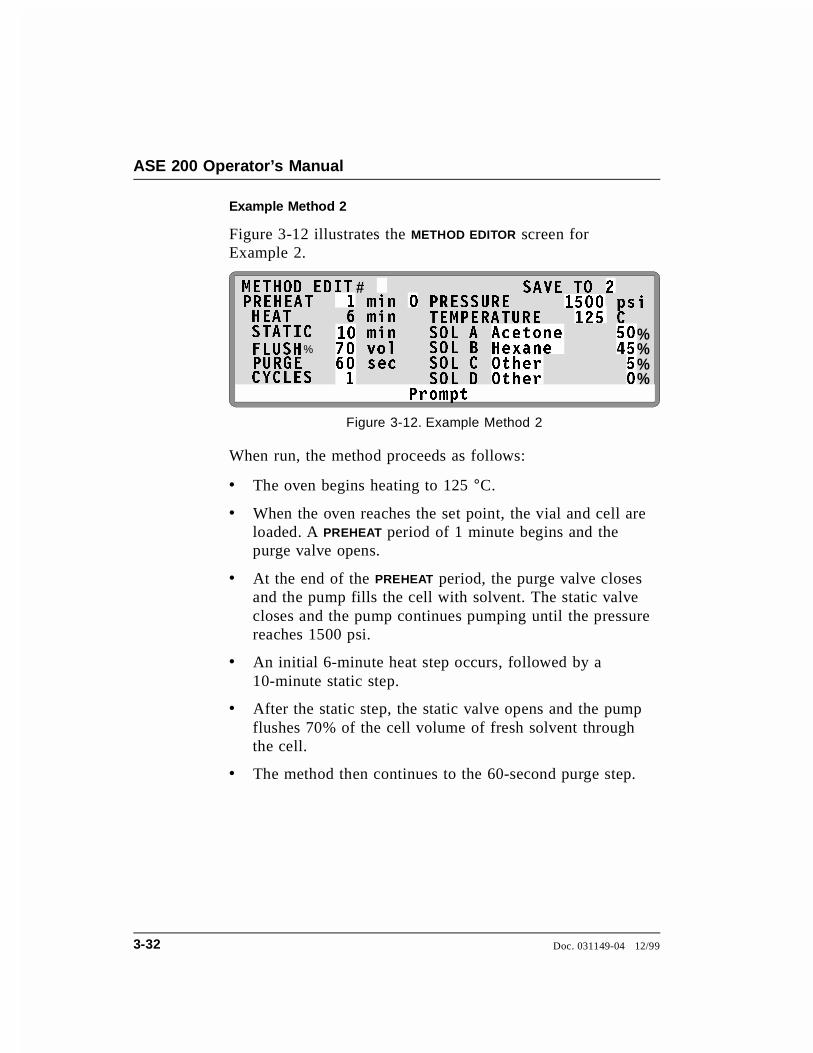
Example Method 2
Figure 3-12 illustrates the METHOD EDITOR screen forExample 2.
When run, the method proceeds as follows:
• The oven begins heating to 125 °C.
• When the oven reaches the set point, the vial and cell areloaded. A PREHEAT period of 1 minute begins and thepurge valve opens.
• At the end of the PREHEAT period, the purge valve closesand the pump fills the cell with solvent. The static valvecloses and the pump continues pumping until the pressurereaches 1500 psi.
• An initial 6-minute heat step occurs, followed by a10-minute static step.
• After the static step, the static valve opens and the pumpflushes 70% of the cell volume of fresh solvent throughthe cell.
• The method then continues to the 60-second purge step.
3URPSW
0(7+2' (',7 6$9( 72
+($7 PLQSVL&
PLQ %YRO %VHF %
67$7,&)/86+385*(&<&/(6
35(6685(7(03(5$785(62/ $62/ %62/ &��
�
���
��
�����
�
�� $FHWRQH+H[DQH
��
2WKHU �
#
��
62/ ' 2WKHU %�
%
35(+($7 PLQ� 2
Figure 3-12. Example Method 2
ASE 200 Operator’s Manual
3-32 Doc. 031149-04 12/99

Example Method 3
Figure 3-13 illustrates the METHOD EDITOR screen forExample 3.
When run, the method proceeds as follows:
• The oven begins heating to 150 °C.
• When the oven reaches the set point, the vial and cell areloaded. The pump fills the cell with solvent. The staticvalve closes and the pump continues pumping until thepressure reaches 2000 psi.
• An initial 7-minute heat step occurs, followed by the first5-minute static step.
• After the static step, the static valve opens and the pumpflushes 25% of the cell volume of fresh solvent throughthe cell. This amount is one-half of the total of 50% to beflushed through in the two cycles.
• The static and flush steps are repeated. The method thencontinues to the 60-second purge step.
3URPSW
0(7+2' (',7 6$9( 72
PLQSVL&
PLQ %YRO %VHF %
67$7,&)/86+�385*(&<&/(6
35(6685(7(03(5$785(62/ $62/ %62/ &��
�
���
��
����
�
� $FHWRQH0H&O�
��
2WKHU �
#
��
62/ ' 2WKHU %�
35(+($7+($7
PLQ�
22
Figure 3-13. Example Method 3
3 • Operation and Maintenance
Doc. 031149-04 12/99 3-33
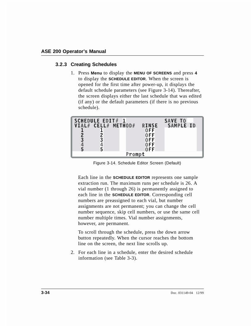
3.2.3 Creating Schedules
1. Press Menu to display the MENU OF SCREENS and press 4to display the SCHEDULE EDITOR. When the screen isopened for the first time after power-up, it displays thedefault schedule parameters (see Figure 3-14). Thereafter,the screen displays either the last schedule that was edited(if any) or the default parameters (if there is no previousschedule).
Each line in the SCHEDULE EDITOR represents one sampleextraction run. The maximum runs per schedule is 26. Avial number (1 through 26) is permanently assigned toeach line in the SCHEDULE EDITOR. Corresponding cellnumbers are preassigned to each vial, but numberassignments are not permanent; you can change the cellnumber sequence, skip cell numbers, or use the same cellnumber multiple times. Vial number assignments,however, are permanent.
To scroll through the schedule, press the down arrowbutton repeatedly. When the cursor reaches the bottomline on the screen, the next line scrolls up.
2. For each line in a schedule, enter the desired scheduleinformation (see Table 3-3).
Figure 3-14. Schedule Editor Screen (Default)
ASE 200 Operator’s Manual
3-34 Doc. 031149-04 12/99

3. Move the cursor to the SAVE TO field. Enter a number forthe new schedule (1-24), or press Select ∆ to display thenext unused schedule number, and then press Enter tosave.
Schedule Field Description Values
CELL Initially, the cell numbers correspond to thevial numbers (cell 1 is assigned to vial 1,cell 2 is assigned to vial 2, etc.). However,you can enter a different cell number. Forexample, when performing multipleextractions on the same sample, assign onesample cell to multiple (up to 26) vials (seeExample Schedule 3 on page 3-38).
1 through 24
METHOD Enter the number of the method to run. Adifferent method can be run on each sample.
Because the oven heats up faster than itcools down, it is advisable to enter methodsin a schedule from coolest to hottest. Thisminimizes the oven wait time betweenmethods.
1 through 24
RINSE Specify whether a rinse is performed aftereach extraction and which solvent is used.When an ASE 200 Solvent Controller is inoperation, select ON if the last solvent wasa mixture; otherwise, specify the solvent inbottle A, B, C, or D. Initially, this fieldcontains the default value from theMODULE SETUP screen (see Section 3.1.7).Changing this field overrides the setup value.
OFF=norinse,ON=lastsolventused; ON A,ON B, ONC, and OND=solvent incorrespondingbottle
SAMPLE ID Enter an identification number for thesample (optional).
Up to 10numericcharacters
Table 3-3. Schedule Parameters
3 • Operation and Maintenance
Doc. 031149-04 12/99 3-35
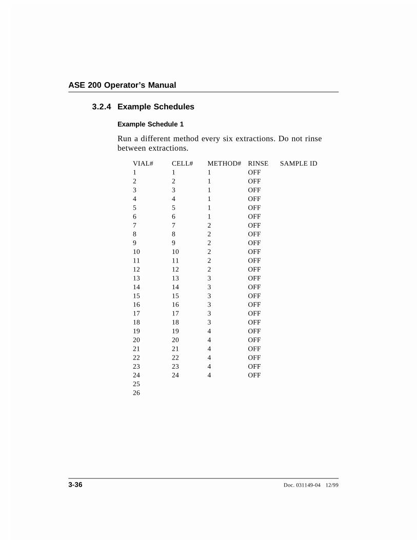
3.2.4 Example Schedules
Example Schedule 1
Run a different method every six extractions. Do not rinsebetween extractions.
VIAL# CELL# METHOD# RINSE SAMPLE ID1 1 1 OFF2 2 1 OFF3 3 1 OFF4 4 1 OFF5 5 1 OFF6 6 1 OFF7 7 2 OFF8 8 2 OFF9 9 2 OFF10 10 2 OFF11 11 2 OFF12 12 2 OFF13 13 3 OFF14 14 3 OFF15 15 3 OFF16 16 3 OFF17 17 3 OFF18 18 3 OFF19 19 4 OFF20 20 4 OFF21 21 4 OFF22 22 4 OFF23 23 4 OFF24 24 4 OFF2526
ASE 200 Operator’s Manual
3-36 Doc. 031149-04 12/99
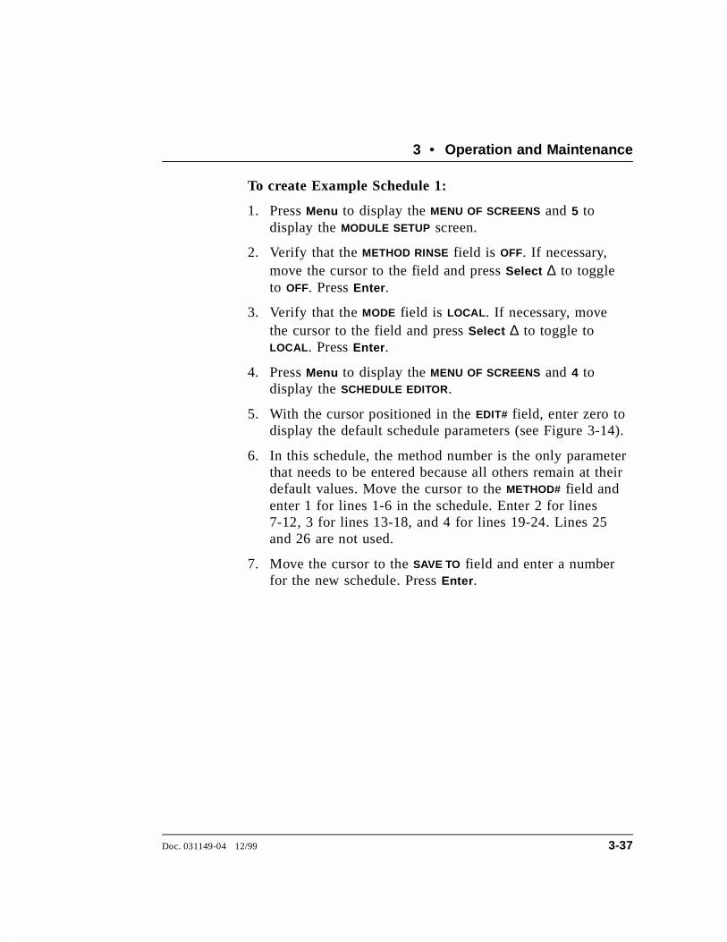
To create Example Schedule 1:
1. Press Menu to display the MENU OF SCREENS and 5 todisplay the MODULE SETUP screen.
2. Verify that the METHOD RINSE field is OFF. If necessary,move the cursor to the field and press Select ∆ to toggleto OFF. Press Enter.
3. Verify that the MODE field is LOCAL. If necessary, movethe cursor to the field and press Select ∆ to toggle toLOCAL. Press Enter.
4. Press Menu to display the MENU OF SCREENS and 4 todisplay the SCHEDULE EDITOR.
5. With the cursor positioned in the EDIT# field, enter zero todisplay the default schedule parameters (see Figure 3-14).
6. In this schedule, the method number is the only parameterthat needs to be entered because all others remain at theirdefault values. Move the cursor to the METHOD# field andenter 1 for lines 1-6 in the schedule. Enter 2 for lines7-12, 3 for lines 13-18, and 4 for lines 19-24. Lines 25and 26 are not used.
7. Move the cursor to the SAVE TO field and enter a numberfor the new schedule. Press Enter.
3 • Operation and Maintenance
Doc. 031149-04 12/99 3-37
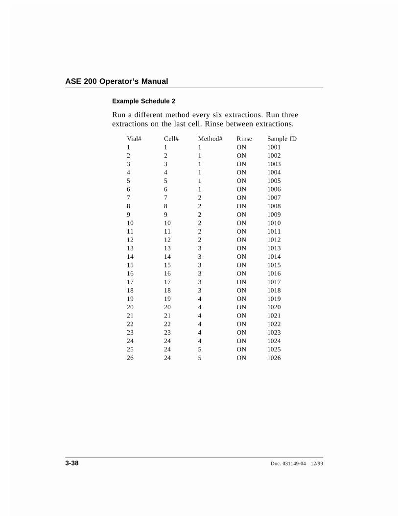
Example Schedule 2
Run a different method every six extractions. Run threeextractions on the last cell. Rinse between extractions.
Vial# Cell# Method# Rinse Sample ID1 1 1 ON 10012 2 1 ON 10023 3 1 ON 10034 4 1 ON 10045 5 1 ON 10056 6 1 ON 10067 7 2 ON 10078 8 2 ON 10089 9 2 ON 100910 10 2 ON 101011 11 2 ON 101112 12 2 ON 101213 13 3 ON 101314 14 3 ON 101415 15 3 ON 101516 16 3 ON 101617 17 3 ON 101718 18 3 ON 101819 19 4 ON 101920 20 4 ON 102021 21 4 ON 102122 22 4 ON 102223 23 4 ON 102324 24 4 ON 102425 24 5 ON 102526 24 5 ON 1026
ASE 200 Operator’s Manual
3-38 Doc. 031149-04 12/99
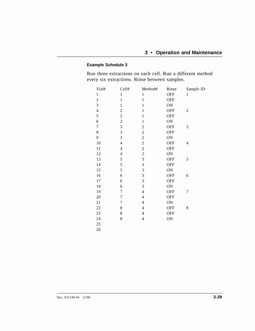
Example Schedule 3
Run three extractions on each cell. Run a different methodevery six extractions. Rinse between samples.
Vial# Cell# Method# Rinse Sample ID1 1 1 OFF 12 1 1 OFF3 1 1 ON4 2 1 OFF 25 2 1 OFF6 2 1 ON7 3 2 OFF 38 3 2 OFF9 3 2 ON10 4 2 OFF 411 4 2 OFF12 4 2 ON13 5 3 OFF 514 5 3 OFF15 5 3 ON16 6 3 OFF 617 6 3 OFF18 6 3 ON19 7 4 OFF 720 7 4 OFF21 7 4 ON22 8 4 OFF 823 8 4 OFF24 8 4 ON2526
3 • Operation and Maintenance
Doc. 031149-04 12/99 3-39

3.3 Method Development Guidelines
Follow the procedure below when developing a method for a newsample type:
1. Select a solvent(s) (see Section 3.1.1).
2. Prepare the sample (see Section 4.).
3. Select a cell size (see Section 3.1.4).
4. Create a new method with default operating parameters. To dothis, go to the METHOD EDITOR screen, position the cursor in theEDIT# field, and enter zero to display the default parameters.Move the cursor to the SAVE TO field and select a new methodnumber (2, for example). Press Enter to save the method.
5. Create a schedule that extracts the same sample three times intoseparate vials (see the example in Figure 3-15). Specify themethod created in Step 4 for each extraction.
6. Run the schedule and analyze the extracts.
7. If target analytes are present in vial 2 or 3, make the followingadjustments (one at a time) to the method:
a. Raise the temperature. In general, raising the temperatureincreases the efficiency of the extraction process. However,because compounds can degrade at high temperature, it isbest to keep the temperature below the maximum allowed(200 °C). If oxidation is a concern, degas the solvent beforeuse.
Figure 3-15. Example Schedule for Method Development
ASE 200 Operator’s Manual
3-40 Doc. 031149-04 12/99

b. Run two static/flush cycles. Extending the static timeenhances diffusion of the analytes into the extraction fluid.Separating the static time into two cycles, rather than usingone longer cycle, allows the introduction of fresh solventmidway through. The fresh solvent helps maintain a favorablesolvent/sample equilibrium for samples that are heavilyloaded or otherwise difficult to extract.
c. Increase the flush volume to allow more solvent to passthrough the sample. The flush volume can be up to 150% ofthe cell volume.
NOTETo prevent overfilling the 33 mL cells, it may be necessaryto balance the number of static cycles and flush volume.
8. After each adjustment, repeat the schedule and analyze theextract. When target analytes no longer appear in the extractfrom the second vial, the method is complete for this sample type.
NOTEThe ASE 200 uses pressure to maintain the extractionsolvents as liquids when the solvents are heated abovetheir boiling points, as well as to fill the extraction cellsquickly. Setting the pressure above 13.8 MPa (2000 psi)has little or no effect on analyte recovery.
9. If analytes still appear in the extract from the second vial, makethe following adjustments (one at a time) to the method:
• Run three static/flush cycles.
• Raise the temperature again.
• Increase static time.
• Select a different solvent.
3 • Operation and Maintenance
Doc. 031149-04 12/99 3-41

3.4 Running Extractions
3.4.1 Running Under Method Control
Before running an extraction, you must create a method thatdefines operating conditions for the run. Section 3.2.1explains how to create methods from the ASE 200 frontpanel. For instructions on creating methods with AutoASEsoftware, refer to the software manual.
After running, a report of the run can be printed (seeSection 3.6). Print the report before starting the next run;information about a run is cleared from memory when thenext run starts.
A default method is available to enable you to get startedrunning quickly, before creating any custom methods. Beforerunning the default method, assign a method number to it.
To number the default method:
1. Press Menu to display the MENU OF SCREENS and press 3to display the METHOD EDITOR.
2. With the cursor in the EDIT# field, enter zero to displaythe default parameters (see Figure 3-16).
3. Move the cursor to the SAVE TO field; press Select ∆ todisplay the next unused method number and press Enter.This new method can now be loaded and run.
3URPSW
0(7+2' (',7 6$9( 7235(+($7
PLQSVL&
���PLQ%YRO%VHF %
67$7,&)/86+�385*(&<&/(6
35(6685(7(03(5$785(62/ $62/ %62/ &��
���
��
�����
�
�
#
27+(5
27+(527+(5 �
62/ '27+(527+(5 %�
%
�
+($7PLQ &�
Figure 3-16. Method Editor Screen (Default)
ASE 200 Operator’s Manual
3-42 Doc. 031149-04 12/99

To load a method and start the run:
4. Press Menu to display the MENU OF SCREENS, and pressEnter (or 1) to display the LOAD METHOD OR SCHEDULE
screen (see Figure 3-17).
5. Verify that METHOD appears in the LOAD field. If not, pressSelect ∆ to toggle to METHOD.
6. By default, the method begins running at vial 1. To startthe method run at a different vial, move the cursor to theVIAL field and enter the desired number.
7. Move the cursor to the NUMBER field and enter thenumber of the method. Press Enter or a cursor arrow. Thiscloses the LOAD METHOD OR SCHEDULE screen and opensthe CURRENT STATUS screen, displaying the methodnumber and the status of other ASE 200 operatingparameters (see Figure 3-18).
Figure 3-17. Load Method or Schedule Screen
°
/2&$/
Figure 3-18. Current Status Screen
3 • Operation and Maintenance
Doc. 031149-04 12/99 3-43
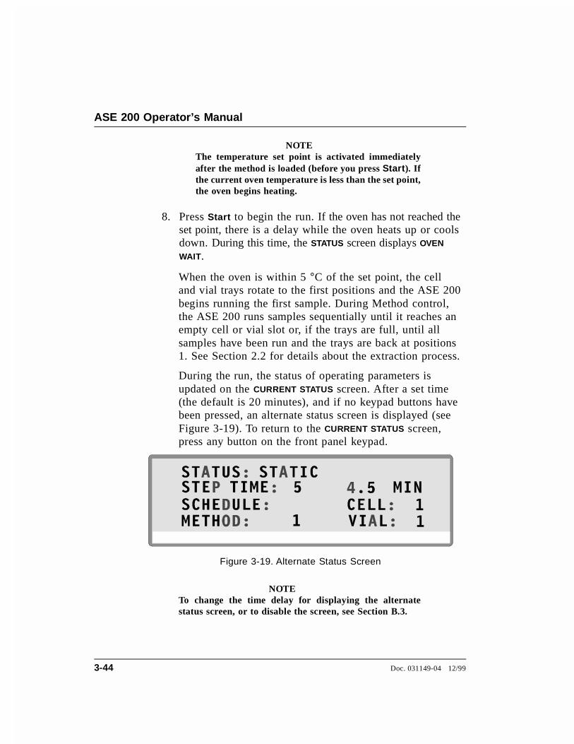
NOTEThe temperature set point is activated immediatelyafter the method is loaded (before you press Start). Ifthe current oven temperature is less than the set point,the oven begins heating.
8. Press Start to begin the run. If the oven has not reached theset point, there is a delay while the oven heats up or coolsdown. During this time, the STATUS screen displays OVEN
WAIT.
When the oven is within 5 °C of the set point, the celland vial trays rotate to the first positions and the ASE 200begins running the first sample. During Method control,the ASE 200 runs samples sequentially until it reaches anempty cell or vial slot or, if the trays are full, until allsamples have been run and the trays are back at positions1. See Section 2.2 for details about the extraction process.
During the run, the status of operating parameters isupdated on the CURRENT STATUS screen. After a set time(the default is 20 minutes), and if no keypad buttons havebeen pressed, an alternate status screen is displayed (seeFigure 3-19). To return to the CURRENT STATUS screen,press any button on the front panel keypad.
NOTETo change the time delay for displaying the alternatestatus screen, or to disable the screen, see Section B.3.
Figure 3-19. Alternate Status Screen
ASE 200 Operator’s Manual
3-44 Doc. 031149-04 12/99
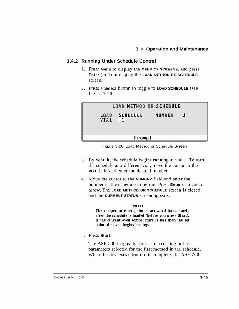
3.4.2 Running Under Schedule Control
1. Press Menu to display the MENU OF SCREENS, and pressEnter (or 1) to display the LOAD METHOD OR SCHEDULE
screen.
2. Press a Select button to toggle to LOAD SCHEDULE (seeFigure 3-20).
3. By default, the schedule begins running at vial 1. To startthe schedule at a different vial, move the cursor to theVIAL field and enter the desired number.
4. Move the cursor to the NUMBER field and enter thenumber of the schedule to be run. Press Enter or a cursorarrow. The LOAD METHOD OR SCHEDULE screen is closedand the CURRENT STATUS screen appears.
NOTEThe temperature set point is activated immediatelyafter the schedule is loaded (before you press Start).If the current oven temperature is less than the setpoint, the oven begins heating.
5. Press Start.
The ASE 200 begins the first run according to theparameters selected for the first method in the schedule.When the first extraction run is complete, the ASE 200
Figure 3-20. Load Method or Schedule Screen
3 • Operation and Maintenance
Doc. 031149-04 12/99 3-45
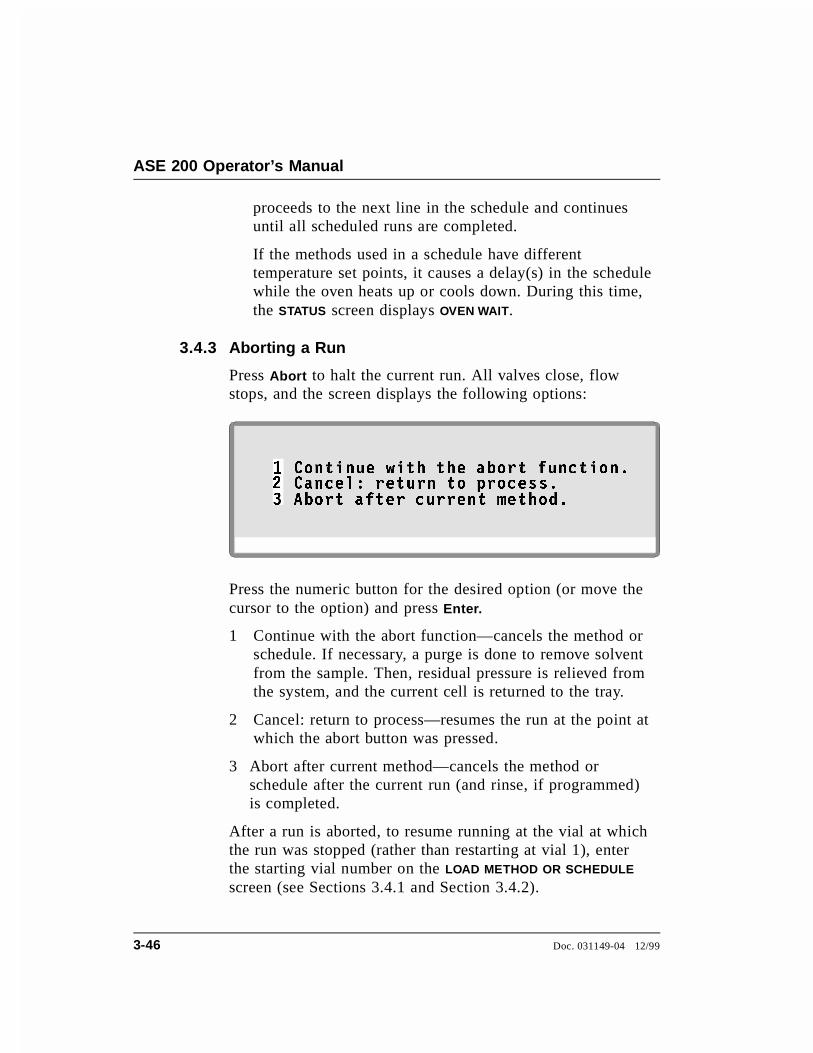
proceeds to the next line in the schedule and continuesuntil all scheduled runs are completed.
If the methods used in a schedule have differenttemperature set points, it causes a delay(s) in the schedulewhile the oven heats up or cools down. During this time,the STATUS screen displays OVEN WAIT.
3.4.3 Aborting a Run
Press Abort to halt the current run. All valves close, flowstops, and the screen displays the following options:
Press the numeric button for the desired option (or move thecursor to the option) and press Enter.
1 Continue with the abort function—cancels the method orschedule. If necessary, a purge is done to remove solventfrom the sample. Then, residual pressure is relieved fromthe system, and the current cell is returned to the tray.
2 Cancel: return to process—resumes the run at the point atwhich the abort button was pressed.
3 Abort after current method—cancels the method orschedule after the current run (and rinse, if programmed)is completed.
After a run is aborted, to resume running at the vial at whichthe run was stopped (rather than restarting at vial 1), enterthe starting vial number on the LOAD METHOD OR SCHEDULE
screen (see Sections 3.4.1 and Section 3.4.2).
&RQWLQXH ZLWK WKH DERUW IXQFWLRQ�&DQFHO� UHWXUQ WR SURFHVV��
�
� $ERUW DIWHU FXUUHQW PHWKRG�
ASE 200 Operator’s Manual
3-46 Doc. 031149-04 12/99

3.5 Post-Extraction Procedures
3.5.1 Cleaning the Cells
Cells are extremely hot after an extraction. Allow cells tocool for at least 15 minutes before handling. Be especiallycautious with cells that have been heated over 50 °C.
After use, empty the cells and rinse the cell caps and cellbodies with water or organic solvent. For most applications,simply rinsing the end caps is sufficient. If necessary,disassemble the end caps and sonicate or soak in solvent. Cellbodies (but not the caps) can be cleaned in a dishwasher orhigh-temperature cleaning unit. Do not exceed 400 °C whenperforming high-temperature cleaning.
Disassemble the end caps and sonicate or soak in solvent. SeeSection 5.1 for disassembly instructions.
3.5.2 Processing Extracts
The composition of the extracts generated by the ASE 200 isvery close to that generated by Soxhlet and other standardliquid extraction techniques when using the same solvent.Use the same analytical method for the ASE extracts that youemployed for extracts obtained from other techniques.
NOTEAn external device can be interfaced with the ASE 200system to automatically process the sample extracts. SeeSection 3.1.8 for details.
3 • Operation and Maintenance
Doc. 031149-04 12/99 3-47
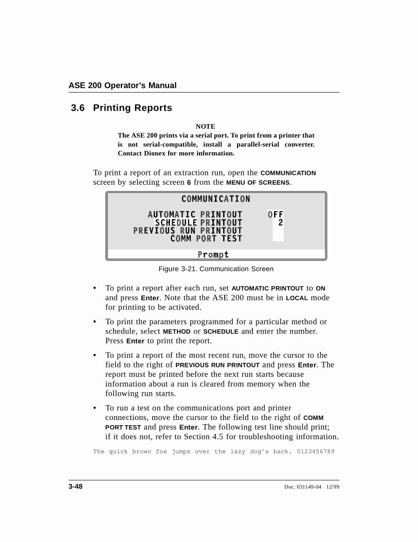
3.6 Printing Reports
NOTEThe ASE 200 prints via a serial port. To print from a printer thatis not serial-compatible, install a parallel-serial converter.Contact Dionex for more information.
To print a report of an extraction run, open the COMMUNICATION
screen by selecting screen 6 from the MENU OF SCREENS.
• To print a report after each run, set AUTOMATIC PRINTOUT to ON
and press Enter. Note that the ASE 200 must be in LOCAL modefor printing to be activated.
• To print the parameters programmed for a particular method orschedule, select METHOD or SCHEDULE and enter the number.Press Enter to print the report.
• To print a report of the most recent run, move the cursor to thefield to the right of PREVIOUS RUN PRINTOUT and press Enter. Thereport must be printed before the next run starts becauseinformation about a run is cleared from memory when thefollowing run starts.
• To run a test on the communications port and printerconnections, move the cursor to the field to the right of COMM
PORT TEST and press Enter. The following test line should print;if it does not, refer to Section 4.5 for troubleshooting information.
The quick brown fox jumps over the lazy dog’s back. 0123456789
Figure 3-21. Communication Screen
ASE 200 Operator’s Manual
3-48 Doc. 031149-04 12/99

3.7 Routine Maintenance
This section describes routine maintenance procedures that may beperformed by the user. All other maintenance procedures must beperformed by Dionex personnel.
3.7.1 Daily Maintenance
• Fill the solvent reservoir, if needed. Run a rinse cycleafter filling.
• Empty the waste vial, if needed.
• Empty the rinse vials.
• Check the gases.
• Check for leaks from the solvent reservoir, pump, valves,and other components in the flow path (see Figure 3-22).Wipe up liquids and tighten or replace leaking fittings(see Section 5.2).
3.7.2 Periodic Maintenance
• Replace the external O-rings (P/N 049457, pkg. of 50Teflon O-rings; P/N 056325, pkg. of 50 Viton O-rings) inthe cell caps and rinse tubes approximately every 50 to 75extractions, or when worn.
NOTEViton O-rings are available for high temperatureapplications, such as dioxins.
• Replace the PEEK seals (P/N 049455, pkg. of 10;P/N 049454, pkg. of 50) inside the cell caps afterapproximately every 50 to 75 extractions (see Section 5.1).
• Verify that the two needles on the needle mechanism arestraight. See Section 5.7 for replacement instructions.
• Replace the septa in the rinse vials.
3 • Operation and Maintenance
Doc. 031149-04 12/99 3-49

To NSupply
2
To Vent onR ear Panel
To Vent onR ear Panel
Figure 3-22. Solvent Flow Schematic
ASE 200 Operator’s Manual
3-50 Doc. 031149-04 12/99

3.8 Shutdown
• If the solvent is 100% organic, simply turn off the power forovernight shutdown.
• If the solvent contains acids or other strong additives, rinse thesystem with a 100% organic solvent or with distilled waterbefore overnight shutdown.
• For longer shutdowns, also turn off the gas and compressed airsupplies.
• Before shipping the ASE 200, empty all solvent bottles andreconnect them to the system. Then run one or more rinse cyclesto remove solvent from the lines.
NOTEIf there is no input to the ASE 200 for four hours (no controlpanel buttons are pressed and no commands are received fromAutoASE software), the oven is automatically shut off.
3 • Operation and Maintenance
Doc. 031149-04 12/99 3-51

ASE 200 Operator’s Manual
3-52 Doc. 031149-04 12/99

4 • Troubleshooting
This chapter is a guide to troubleshooting problems that may occurwhile operating the ASE 200 Accelerated Solvent Extractor. Turn tothe section that best describes the operating problem. There, possiblecauses of the problem are listed in order of probability, along withthe recommended courses of action.
If the screen displays an error message, check the list of errormessages for possible causes.
If you are unable to eliminate a problem, contact Dionex. In theU.S., call 1-800-346-6390 and select the Technical Support option.Outside the U.S., call the nearest Dionex office.
4.1 Error Messages
When an error occurs, an error message is displayed on the screen.The message remains until you press a key to clear it, or until it isreplaced by another error message. Each message is identified by anumber in the lower-right corner of the screen.
The ERROR LOG screen lists all errors that occurred during a givenrun. The screen also identifies the cell and vial number in use whenthe error occurred. See Section C.3 for details.
• 212 You forgot to save your method after editing it. PressENTER again to abandon it permanently or press anyother key to finish editing this method.
Cause: After editing a method, but before saving theediting changes, you tried to load a different method.
Action: If you do not want to save the editing changes,press Enter to retain the method in its previously savedversion.
Action: If you want to continue editing the method, pressany key. When you finish editing, move the cursor to the
Doc. 031149-04 12/99 4-1
SAVE TO field and press Enter to save the changes to thecurrent method number. To save the changes to a differentnumber, move the cursor to the SAVE TO field and enter anew (unused) method number, or press Select ∆ to displaythe next unused method number. Press Enter to save themethod.
• 224 You forgot to save your method after editing it. PressMENU again to abandon it permanently or press anykey other than ENTER to finish editing the method.
Cause: After editing a method, but before saving theediting changes, you pressed the Menu button to exit theMETHOD EDITOR screen.
Action: If you do not want to save the editing changes,press Menu again to retain the method in its previouslysaved version.
Action: If you want to continue editing the method, pressany key. When you finish editing, move the cursor to theSAVE TO field and press Enter to save the changes to thecurrent method number. To save the changes to a differentnumber, move the cursor to the SAVE TO field and enter anew (unused) method number, or press Select ∆ to displaythe next unused method number. Press Enter to save themethod.
• 248 The instrument is in REMOTE mode. Put the instru-ment in LOCAL mode to use this function.
Cause: When the ASE 200 is in REMOTE mode, somefunctions are disabled and only three keypad buttons arefunctional: Trays, Rinse, and Abort.
Action: Press Menu to display the MENU OF SCREENS andpress 5 to display the MODULE SETUP screen. Move thecursor to the MODE field and press a Select button totoggle the field to LOCAL (see Figure 3-4). Press Enter ora cursor arrow button.
ASE 200 Operator’s Manual
4-2 Doc. 031149-04 12/99
• 300 You pressed an incorrect key for this entry.
Cause: You pressed an invalid key, unexpected for thisentry.
Action: Enter an acceptable value. Table 3-2 lists thevalues allowed for method parameters. Table 3-3 lists thevalues allowed for schedule parameters.
• 301 Detected an error in the database.
Cause: The memory in which the database is stored hasbecome corrupted.
Action: Contact Dionex for assistance.
• 302 There is an ASE function in progress. Please wait forfunction to complete.
Cause: The function in progress must occur by itself, orelse cannot occur at the same time as the function youattempted to initiate.
Action: Wait until the function in progress is completedbefore pressing a front panel button or making an entry onthe screen.
• 303 A valid schedule has not been selected.
Cause: You selected a nonexistent schedule number to run.
Action: Enter a valid schedule number in the NUMBER
field of the LOAD METHOD OR SCHEDULE screen.
4 • Troubleshooting
Doc. 031149-04 12/99 4-3
• 304 There is an error in the composition of the scheduleline.
Cause: The line references a nonexistent method or amethod that contains an error. If thr error is in line 1 ofthe schedule, this message appears when the schedule isloaded. Otherwise, the schedule begins running, but stopswhen it reaches the schedule line with the error.
Action: Check all lines in the schedule. Enter a validmethod number and/or correct the error in the method.Table 3-2 lists the values allowed for method parameters.Table 3-3 lists the values allowed for schedule parameters
• 305 The oven will not come up to temperature.
Cause: The heater cable connection to the power supplyis loose, or there is a problem with a heater component.
Action: Open the upper door. The power supply is on theleft. Check the heater cable plugged into the 4-pinconnector on the power supply; if the cable is plugged infirmly, the problem is with an internal heater component.Contact Dionex for assistance.
• 306 Time-out on flush portion of the method.
Cause: The pump could not deliver the specified flushvolume before the time-out expired. The cell or lines maybe plugged.
Action: Rinse the system to ensure that the pump andvalves are clear. If the rinse runs successfully, the cellmay be plugged. Clean or replace the stainless steel cellfrit (see Section 5.1) and replace the cellulose orglass-fiber filter (see Section 3.1.4). Then, mix the samplewith a dispersing agent (see Section 3.1.3) and run theextraction again.
If the rinse is not successful, the solvent lines may beplugged. Contact Dionex for assistance.
ASE 200 Operator’s Manual
4-4 Doc. 031149-04 12/99
• 307 Time-out condition in loading a collection vial.
Cause: A collection vial was not in the specified positionof the schedule.
Action: Before running a schedule, check that all vialsare in place.
• 308 The collection vial is full.
Cause: The collection vial is full, or the sensor failed todetect it.
Action: Empty the vial. Also, make sure the vial label isnot blocking the area read by the sensor. See Figure 3-3for acceptable vial label locations. If the error messagereappears, contact Dionex for assistance.
• 309 Error time-out condition in loading a cell.
Cause: A cell was not in the specified position of theschedule.
Action: Before beginning a schedule, check that all cellsare in place.
• 310 Error time-out condition in unloading a cell.
Cause: A cell was not in the specified position of theschedule.
Action: Before beginning a schedule, check that all cellsare in place.
• 311 The selected method is not valid or a method has not been selected.
Cause: The selected method is incomplete, or a methodwas not selected.
Action: If you have not done so already, select a method.If the selected method is invalid, make sure there are nomissing steps.
4 • Troubleshooting
Doc. 031149-04 12/99 4-5
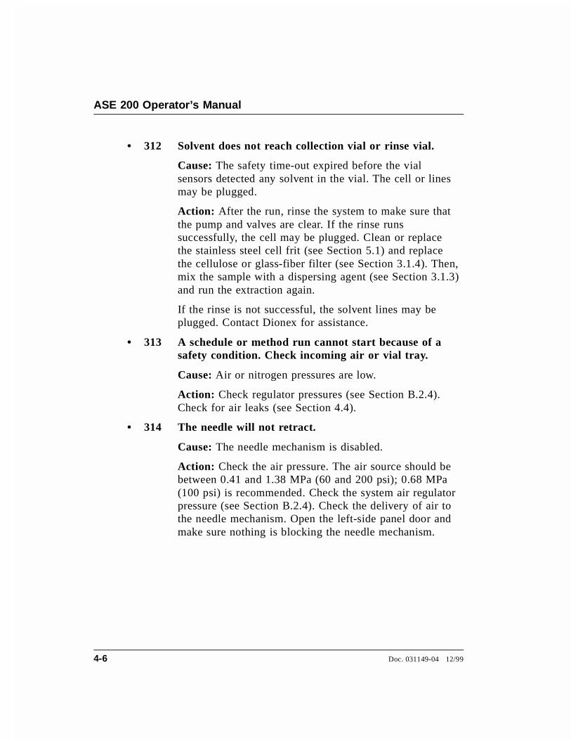
• 312 Solvent does not reach collection vial or rinse vial.
Cause: The safety time-out expired before the vialsensors detected any solvent in the vial. The cell or linesmay be plugged.
Action: After the run, rinse the system to make sure thatthe pump and valves are clear. If the rinse runssuccessfully, the cell may be plugged. Clean or replacethe stainless steel cell frit (see Section 5.1) and replacethe cellulose or glass-fiber filter (see Section 3.1.4). Then,mix the sample with a dispersing agent (see Section 3.1.3)and run the extraction again.
If the rinse is not successful, the solvent lines may beplugged. Contact Dionex for assistance.
• 313 A schedule or method run cannot start because of a safety condition. Check incoming air or vial tray.
Cause: Air or nitrogen pressures are low.
Action: Check regulator pressures (see Section B.2.4).Check for air leaks (see Section 4.4).
• 314 The needle will not retract.
Cause: The needle mechanism is disabled.
Action: Check the air pressure. The air source should bebetween 0.41 and 1.38 MPa (60 and 200 psi); 0.68 MPa(100 psi) is recommended. Check the system air regulatorpressure (see Section B.2.4). Check the delivery of air tothe needle mechanism. Open the left-side panel door andmake sure nothing is blocking the needle mechanism.
ASE 200 Operator’s Manual
4-6 Doc. 031149-04 12/99

• 315 Vial tray will not home.
Cause: The tray is blocked or disabled, or the sensor isout.
Action: Make sure nothing is physically blocking the tray.Manually check the tray movement. If necessary, contactDionex for assistance.
• 316 WARNING: Rinse vials are missing or full. Pleaseempty and replace rinse vials. Press ENTER tocontinue.
Cause: Rinse vials are not available for use, or are notdetected by the vial sensors.
Action: Make sure rinse vials are present in the correctpositions (labeled R1, R2, R3, and R4) of the vial tray. Ifthe rinse vials are full, empty or replace them.
Action: Make sure the vial label is not blocking the arearead by the vial sensors. See Figure 3-3 for acceptablelocations for vial labels. If the error message reappears,contact Dionex for assistance.
• 317 Needle will not engage or a collection vial is not present.
Cause: A collection vial was not in the specified positionof the schedule, or the movement of the needle assemblyto the tray is physically blocked.
Action: Before beginning a schedule, check that all vialsare in place. Open the left-side panel door and make surenothing is blocking the needle mechanism.
• 318 Vial will not go to position.
Cause: The vial tray is incorrectly installed.
Action: Contact Dionex for assistance.
4 • Troubleshooting
Doc. 031149-04 12/99 4-7
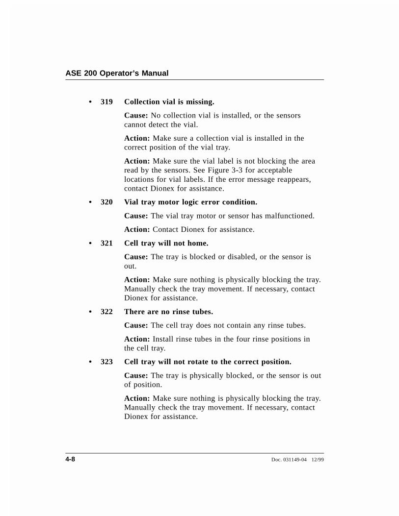
• 319 Collection vial is missing.
Cause: No collection vial is installed, or the sensorscannot detect the vial.
Action: Make sure a collection vial is installed in thecorrect position of the vial tray.
Action: Make sure the vial label is not blocking the arearead by the sensors. See Figure 3-3 for acceptablelocations for vial labels. If the error message reappears,contact Dionex for assistance.
• 320 Vial tray motor logic error condition.
Cause: The vial tray motor or sensor has malfunctioned.
Action: Contact Dionex for assistance.
• 321 Cell tray will not home.
Cause: The tray is blocked or disabled, or the sensor isout.
Action: Make sure nothing is physically blocking the tray.Manually check the tray movement. If necessary, contactDionex for assistance.
• 322 There are no rinse tubes.
Cause: The cell tray does not contain any rinse tubes.
Action: Install rinse tubes in the four rinse positions inthe cell tray.
• 323 Cell tray will not rotate to the correct position.
Cause: The tray is physically blocked, or the sensor is outof position.
Action: Make sure nothing is physically blocking the tray.Manually check the tray movement. If necessary, contactDionex for assistance.
ASE 200 Operator’s Manual
4-8 Doc. 031149-04 12/99

• 324 Cell tray motor logic error condition.
Cause: The cell tray motor or sensor has malfunctioned.
Action: Contact Dionex for assistance.
• 325 The AutoSeal arm will not open.
Cause: The air supply is not reaching the arm.
Action: Check the air pressure. The air source should bebetween 0.41 and 1.38 MPa (60 and 200 psi); 0.68 MPa(100 psi) is recommended. Check the system air regulatorpressure (see Section B.2.4). Check for air leaks (seeSection 4.4).
• 326 There is a cell in the AutoSeal arm.
Cause: The cell was not returned to the tray.
Action: Remove the cell from the arm and place it in thecorrect position in the tray.
• 327 The AutoSeal arm will not move to the tray.
Cause: The air supply is not reaching the arm.
Action: Check the air pressure. The air source should bebetween 0.41 and 1.38 MPa (60 and 200 psi); 0.68 MPa(100 psi) is recommended. Check the system air regulatorpressure (see Section B.2.4). Check for air leaks (seeSection 4.4).
Cause: The arm is hitting the cell tray.
Action: The arm is out of alignment. Contact Dionex forassistance.
• 328 No cell present at this position.
Cause: No cell is installed, or the sensors cannot detect it.
Action: Make sure a cell is installed in the correctposition in the tray. If the sensors do not detect theinstalled cell, contact Dionex for assistance.
4 • Troubleshooting
Doc. 031149-04 12/99 4-9

• 329 The AutoSeal arm will not move to the oven.
Cause: The air supply is not reaching the arm.
Action: Check the air pressure. The air source should bebetween 0.41 and 1.38 MPa (60 and 200 psi); 0.68 MPa(100 psi) is recommended. Check the system air regulatorpressure (see Section B.2.4). Check for air leaks (seeSection 4.4).
• 331 The entered value for this parameter is not in range.Please re-enter value.
Cause: The value is too high or too low for this parameter.
Action: Enter an acceptable value. Table 3-2 lists thevalues allowed for method parameters. Table 3-3 lists thevalues allowed for schedule parameters.
• 332 Cannot perform the rinse function because anotherfunction is in progress.
Cause: The Rinse button functions only when the ASE200 is idle. (The LED on the left of the Start button islighted when the ASE 200 is idle.)
Action: Wait until the function in progress is completedbefore pressing the Rinse button.
• 333 Cannot engage the tray motors at this time becauseanother function is in progress.
Cause: The vial tray can be engaged only when the ASE200 is idle. (The LED on the left of the Start button islighted when the ASE 200 is idle.)
Action: Wait until the function in progress is completed,or press the Abort button and select the desired option.
ASE 200 Operator’s Manual
4-10 Doc. 031149-04 12/99
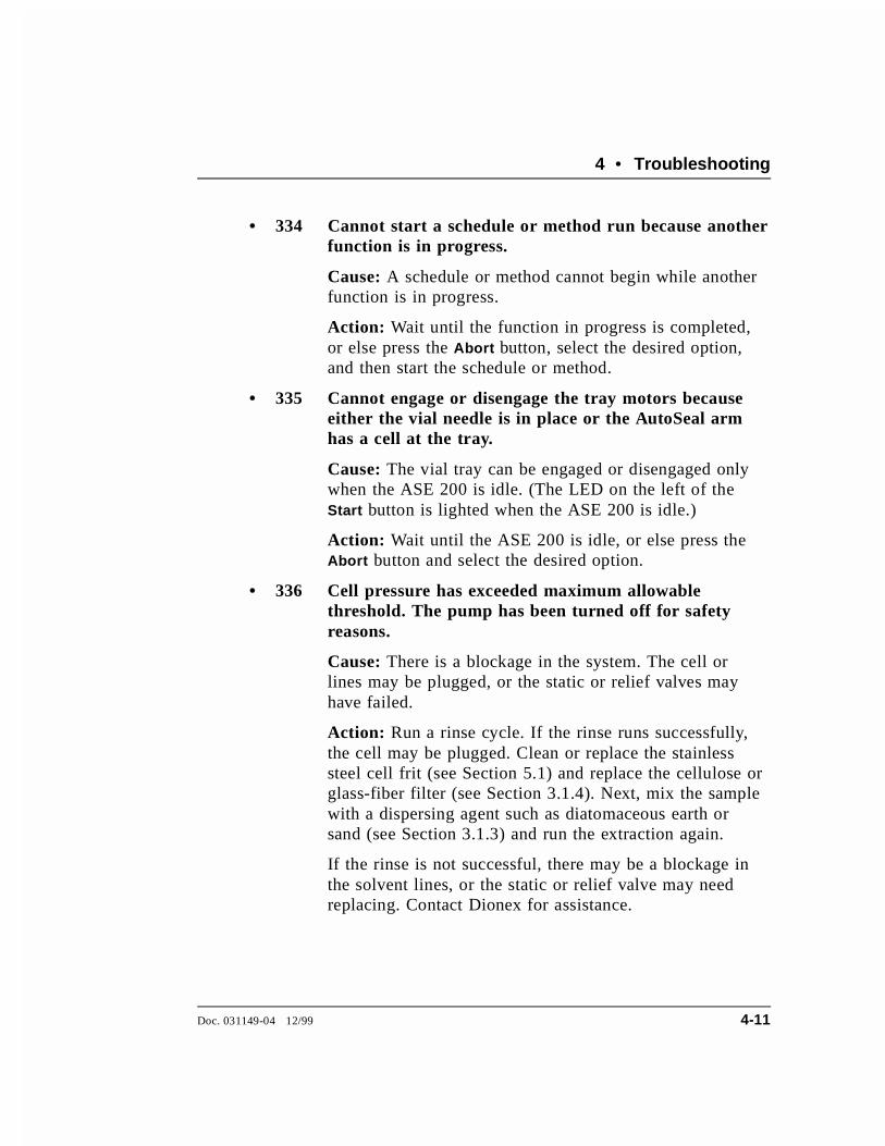
• 334 Cannot start a schedule or method run because anotherfunction is in progress.
Cause: A schedule or method cannot begin while anotherfunction is in progress.
Action: Wait until the function in progress is completed,or else press the Abort button, select the desired option,and then start the schedule or method.
• 335 Cannot engage or disengage the tray motors becauseeither the vial needle is in place or the AutoSeal armhas a cell at the tray.
Cause: The vial tray can be engaged or disengaged onlywhen the ASE 200 is idle. (The LED on the left of theStart button is lighted when the ASE 200 is idle.)
Action: Wait until the ASE 200 is idle, or else press theAbort button and select the desired option.
• 336 Cell pressure has exceeded maximum allowable threshold. The pump has been turned off for safety reasons.
Cause: There is a blockage in the system. The cell orlines may be plugged, or the static or relief valves mayhave failed.
Action: Run a rinse cycle. If the rinse runs successfully,the cell may be plugged. Clean or replace the stainlesssteel cell frit (see Section 5.1) and replace the cellulose orglass-fiber filter (see Section 3.1.4). Next, mix the samplewith a dispersing agent such as diatomaceous earth orsand (see Section 3.1.3) and run the extraction again.
If the rinse is not successful, there may be a blockage inthe solvent lines, or the static or relief valve may needreplacing. Contact Dionex for assistance.
4 • Troubleshooting
Doc. 031149-04 12/99 4-11

• 337 Possible problem with the Temperature RTD. It appears to be shorted.
Cause: The temperature display is inconsistent withnormal operation.
Action: The RTD (Resistive Temperature Device) shouldbe replaced. Contact Dionex for assistance.
• 338 The large cell size requires the large vial size.
Cause: The cell size determines the correct vial size;currently, the cell and vial sizes are mismatched.
Action: Use 60 mL vials with both 22 mL and 33 mLcells.
• 339 A process (schedule/method) in progress. Please wait for completion of task.
Cause: The schedule or method must finish runningbefore a new function is initiated.
Action: Wait until the schedule or method finishesrunning before pressing a front panel button or making anentry on the screen. Or, cancel the process by pressing theAbort button, and then initiate the new task.
• 340 Vial tray has been detected as being absent.
Cause: The vial tray is missing, is incorrectly installed, oris present but cannot be detected by the sensor.
Action: If the vial tray is not present, install it now.
Action: If the tray is installed, turn it manually (in eitherdirection) until you hear a click, indicating that the tray islocked into the correct position. If the error messagereappears, the sensor is malfunctioning. Contact Dionexfor assistance.
ASE 200 Operator’s Manual
4-12 Doc. 031149-04 12/99

• 341 Oven nitrogen pressure is low.
Cause: The nitrogen gas pressure applied to the ovencompression system during an extraction is less than theapproximately 1.03 MPa (130 psi) that is required.
Action: Check the compression oven gauge in the solventreservoir compartment (see Figure B-4 in Appendix B);the gauge should read 130 psi. If it does not, adjust theregulator knob for the gauge (see Figure B-5) until thegauge reads 130 psi.
Action: Adjust the pressure regulator on the nitrogensupply to 0.97 to 1.38 MPa (140 to 200 psi).
Action: If the nitrogen supply is low, replace it.
Action: If there is any drift in the electronics, they mustbe recalibrated. Contact Dionex for assistance.
• 342 Solvent vapor threshold exceeded.
Cause: There may be a leak in the cell.
Action: Tighten the cell caps (hand-tighten only). Checkfor foreign material on the threads of the cap, sealsurface, and cell body. If necessary, replace the O-rings(see Figure 3-2) and/or the PEEK seals (see Section 5.1).
Cause: Solvent may not be completely removed from thecell during the purge cycle (especially with 33 mL cells).
Action: Increase the purge time (see Section 3.2.1).
Cause: There may be a leak in the system.
Action: Open the left-side panel door and visually inspectthe following fittings for leaks (see Figure 4-3): pumpcheck valves, pump fittings, solvent line fittings,transducer fittings, relief valve fittings, and static valvefittings. Tighten or replace any leaking fittings (seeSection 5.2).
4 • Troubleshooting
Doc. 031149-04 12/99 4-13
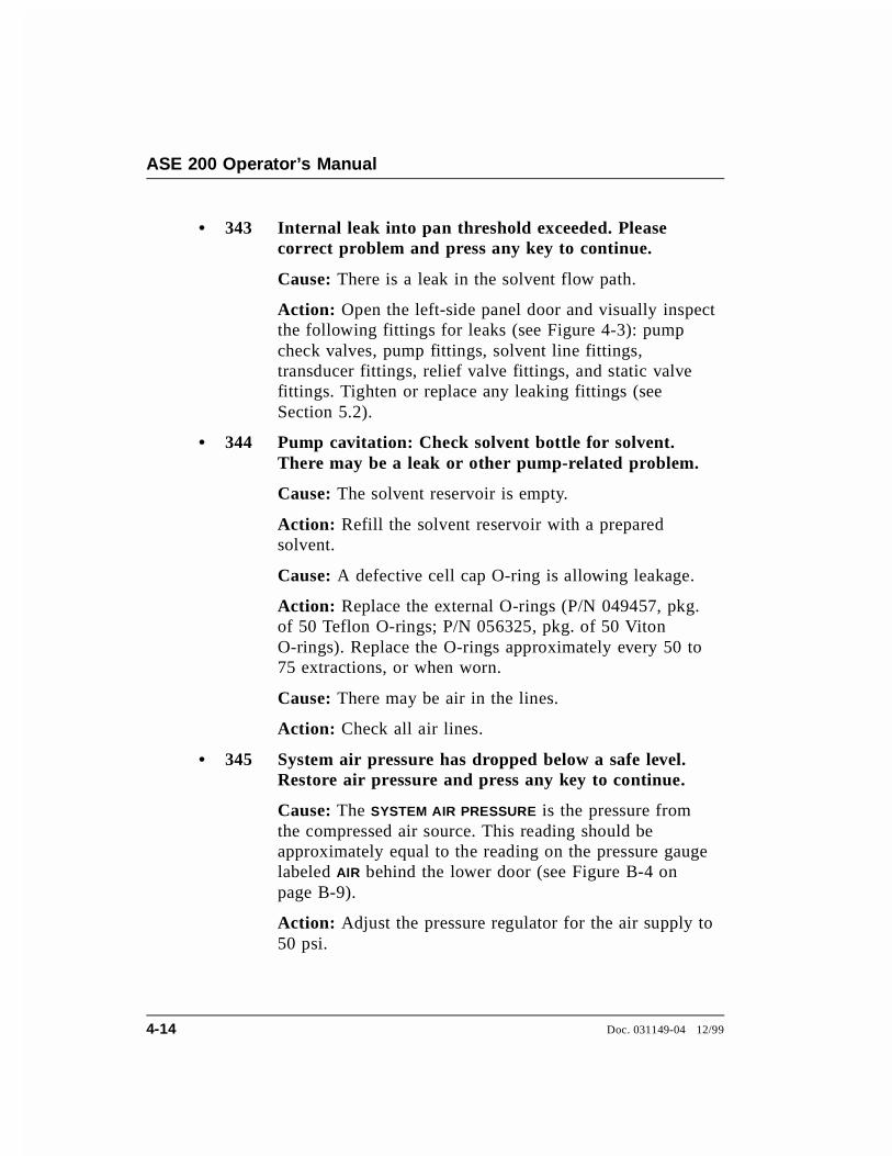
• 343 Internal leak into pan threshold exceeded. Pleasecorrect problem and press any key to continue.
Cause: There is a leak in the solvent flow path.
Action: Open the left-side panel door and visually inspectthe following fittings for leaks (see Figure 4-3): pumpcheck valves, pump fittings, solvent line fittings,transducer fittings, relief valve fittings, and static valvefittings. Tighten or replace any leaking fittings (seeSection 5.2).
• 344 Pump cavitation: Check solvent bottle for solvent. There may be a leak or other pump-related problem.
Cause: The solvent reservoir is empty.
Action: Refill the solvent reservoir with a preparedsolvent.
Cause: A defective cell cap O-ring is allowing leakage.
Action: Replace the external O-rings (P/N 049457, pkg.of 50 Teflon O-rings; P/N 056325, pkg. of 50 VitonO-rings). Replace the O-rings approximately every 50 to75 extractions, or when worn.
Cause: There may be air in the lines.
Action: Check all air lines.
• 345 System air pressure has dropped below a safe level.Restore air pressure and press any key to continue.
Cause: The SYSTEM AIR PRESSURE is the pressure fromthe compressed air source. This reading should beapproximately equal to the reading on the pressure gaugelabeled AIR behind the lower door (see Figure B-4 onpage B-9).
Action: Adjust the pressure regulator for the air supply to50 psi.
ASE 200 Operator’s Manual
4-14 Doc. 031149-04 12/99

Action: If the error message appears again, the electronicsmay need to be recalibrated. Contact Dionex forassistance.
• 346 Total solvent percentage should be equal to 100% to run.
Cause: You attempted to run a method in which the totalfor all solvents does not equal 100%. This may be anolder method, written before the introduction of the ASE200 Solvent Controller.
Action: Adjust the percentages in the method so that thetotal for all solvents equals 100%, save the method, andrestart the run.
Cause: AutoASE downloaded a method in which the totalof the selected solvents does not equal 100%.
Action: Adjust the percentages in the method so that thetotal for all solvents equals 100%, save the method, andrestart the run.
Cause: The total solvent percentage in the method equals100%, but memory is corrupted.
Action: Contact Dionex for assistance.
• 347 The instrument is in REMOTE mode. Put the instru-ment in LOCAL mode to modify this entry.
Cause: In some cases, the ASE 200 must be in LOCAL
mode before you can enter a value on the screen or pressa Select button to toggle a field between parameters.
Action: Press Menu to display the MENU OF SCREENS andpress 5 to display the MODULE SETUP screen. Move thecursor to the MODE field and press a Select button totoggle the field to LOCAL (see Figure 3-4). Press Enter ora cursor arrow button.
4 • Troubleshooting
Doc. 031149-04 12/99 4-15

• 348 The instrument is in REMOTE mode. Put the instru-ment in LOCAL mode to use this function.
Cause: In some cases, the ASE 200 must be in LOCAL
mode before you can operate a particular feature.
Action: Press Menu to display the MENU OF SCREENS andpress 5 to display the MODULE SETUP screen. Move thecursor to the MODE field and press a Select button totoggle the field to LOCAL (see Figure 3-4). Press Enter ora cursor arrow button.
• 349 You forgot to save your method after editing it. PressENTER again to abandon it permanently or pressany other key to finish editing this method.
Cause: You tried to load a new method before savingchanges to the method currently being edited.
Action: If you do not want to save the editing changes,press Enter to abandon them and retain the method in itspreviously saved version. If you want to continue editingthe method, press any key. When you finish editing, youhave two options:
To save the changes to the current method number, movethe cursor to the SAVE TO field and press Enter.
To save the changes to a different method number, movethe cursor to the SAVE TO field and enter a new (unused)schedule number, or press Select ∆ to display the nextunused method number. Press Enter to save the method.
• 350 You forgot to save your method after editing it. PressMENU again to abandon it permanently or press any other key to continue editing the method.
Cause: You pressed Menu before saving changes to themethod currently being edited.
Action: If you do not want to save the editing changes,press Menu again. This retains the method in its
ASE 200 Operator’s Manual
4-16 Doc. 031149-04 12/99

previously saved version. If you want to continue editingthe method, press any key. When you finish editing, youhave two options:
To save the changes to the current method number, movethe cursor to the SAVE TO field and press Enter.
To save the changes to a different method number, movethe cursor to the SAVE TO field and enter a new (unused)method number, or press Select ∆ to display the nextunused method number. Press Enter to save the method.
• 351 You forgot to save your schedule after editing it. PressENTER again to abandon it permanently or pressany other key to finish editing this schedule.
Cause: You tried to load a new schedule before savingchanges to the schedule currently being edited.
Action: If you do not want to save the editing changes,press Enter. This retains the schedule in its previouslysaved version. If you want to continue editing theschedule, press any key. When you finish editing, youhave two options:
To save the changes to the current schedule number, movethe cursor to the SAVE TO field and press Enter.
To save the changes to a different schedule number, movethe cursor to the SAVE TO field and enter a new (unused)schedule number, or press Select ∆ to display the nextunused schedule number. Press Enter to save the schedule.
• 352 You forgot to save your schedule after editing it. PressMENU again to abandon it permanently or pressany other key to continue editing the schedule.
Cause: You pressed Menu before saving changes to theschedule currently being edited.
Action: If you do not want to save the editing changes,press Menu again to abandon them and retain the schedule
4 • Troubleshooting
Doc. 031149-04 12/99 4-17

in its previously saved version. If you want to continueediting the schedule, press any key. When you finishediting, you have two options:
To save the changes to the current schedule number, movethe cursor to the SAVE TO field and press Enter.
To save the changes to a different schedule number, movethe cursor to the SAVE TO field and enter a new (unused)schedule number, or press Select ∆ to display the nextunused schedule number. Press Enter to save the schedule.
• 353 Method cannot be saved if total solvent percentage is not equal to 100%. Check solvent percentage for error.
Cause: You attempted to save a method in which the totalof selected solvents is less than or greater than 100%.
Action: Adjust the percentages so that the total for allsolvents equals 100% and then save the method.
• 354 Hydrocarbon sensor reading is low. Recalibratehydrocarbon baseline. Hydrocarbon sensor may need tobe replaced.
Cause: The hydrocarbon level is significantly lower thanexpected.
Action: Calibrate the hydrocarbon sensor at the earliestopportunity. Refer to Section 5.9 for calibrationinstructions.
Action: If the error message reappears, replace thehydrocarbon sensor. Refer to Section 5.10 for instructionson how to install a new sensor.
• 355 WARNING ONLY: Hydrocarbon sensor reading is low.Recalibrate hydrocarbon baseline, using diagnostic screen.
Cause: The hydrocarbon level is lower than expected.
ASE 200 Operator’s Manual
4-18 Doc. 031149-04 12/99

Action: Calibration of the hydrocarbon sensor isrecommended at this time, but is not required. If you donot calibrate the sensor now, there is a risk that asubsequent run may be aborted unexpectedly. Refer toSection 5.9 for calibration instructions.
• 356 Time-out condition in rotating the collection vial forexternal interface.
Cause: A collection vial was not in the specified positionbefore the time-out expired. The collection vial tray isphysically blocked, or the electronics have malfunctioned.
Action: Turn off the power. Make sure nothing isphysically blocking the tray. Manually check the traymovement. Turn on the power and resume operation.
Action: If the error message reappears, the electronicshave malfunctioned. Contact Dionex for assistance.
• 357 Conflicting entry: Either the vial position is zero or TTL is enabled.
Cause: To have an external device access sample from thecollection vial tray, you must specify a non-zero trayposition and disable the TTL signals.
Action: Press 9 on the MENU OF SCREENS to display theEXTERNAL DEVICE INTERFACE screen. If necessary, movethe cursor to the ROTATE VIAL TRAY TO POSITION field andenter a new (non-zero) position. If necessary, move thecursor to the USE WAIT/CONTINUE TTL SIGNALS field andselect NO. Press Enter or a cursor arrow button to save theediting changes.
4 • Troubleshooting
Doc. 031149-04 12/99 4-19
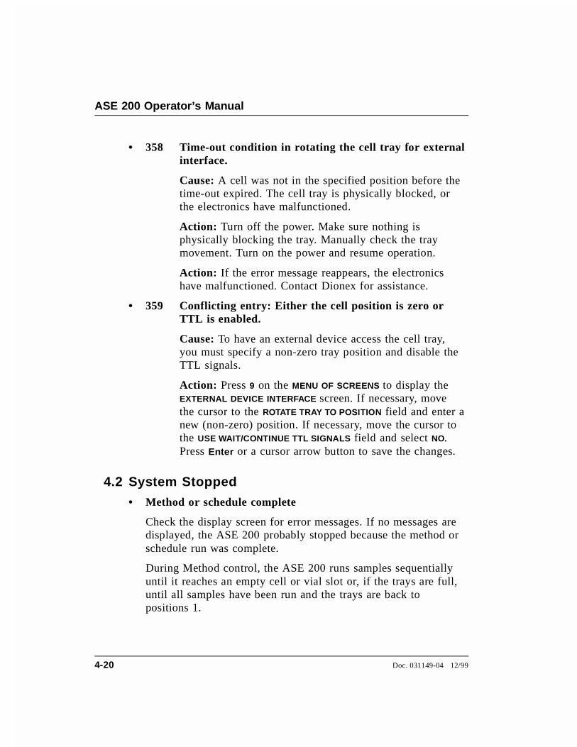
• 358 Time-out condition in rotating the cell tray for externalinterface.
Cause: A cell was not in the specified position before thetime-out expired. The cell tray is physically blocked, orthe electronics have malfunctioned.
Action: Turn off the power. Make sure nothing isphysically blocking the tray. Manually check the traymovement. Turn on the power and resume operation.
Action: If the error message reappears, the electronicshave malfunctioned. Contact Dionex for assistance.
• 359 Conflicting entry: Either the cell position is zero or TTL is enabled.
Cause: To have an external device access the cell tray,you must specify a non-zero tray position and disable theTTL signals.
Action: Press 9 on the MENU OF SCREENS to display theEXTERNAL DEVICE INTERFACE screen. If necessary, movethe cursor to the ROTATE TRAY TO POSITION field and enter anew (non-zero) position. If necessary, move the cursor tothe USE WAIT/CONTINUE TTL SIGNALS field and select NO.
Press Enter or a cursor arrow button to save the changes.
4.2 System Stopped
• Method or schedule complete
Check the display screen for error messages. If no messages aredisplayed, the ASE 200 probably stopped because the method orschedule run was complete.
During Method control, the ASE 200 runs samples sequentiallyuntil it reaches an empty cell or vial slot or, if the trays are full,until all samples have been run and the trays are back topositions 1.
ASE 200 Operator’s Manual
4-20 Doc. 031149-04 12/99
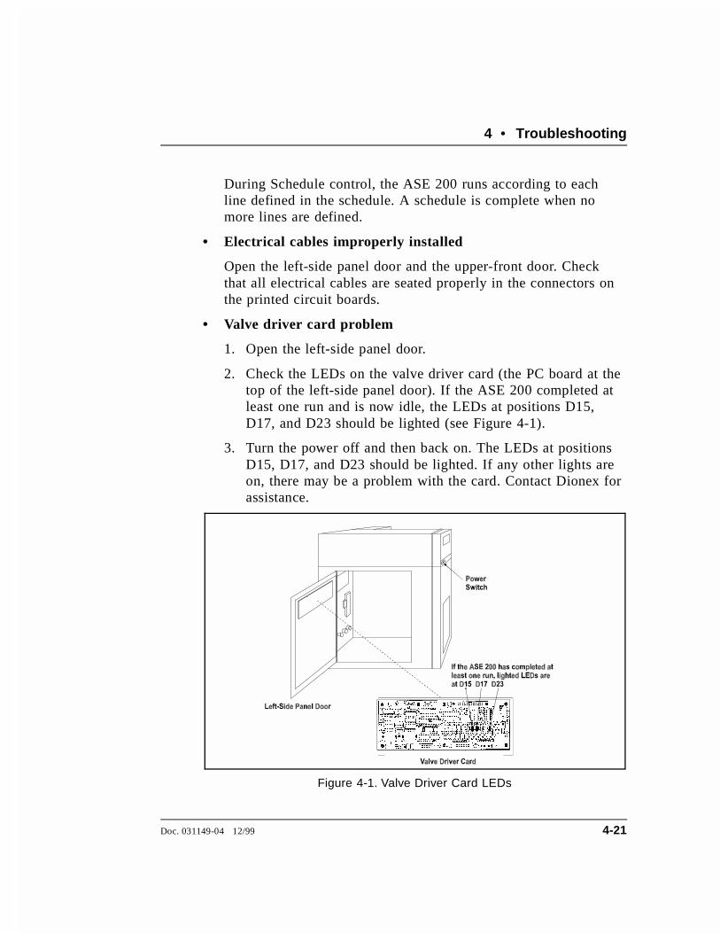
During Schedule control, the ASE 200 runs according to eachline defined in the schedule. A schedule is complete when nomore lines are defined.
• Electrical cables improperly installed
Open the left-side panel door and the upper-front door. Checkthat all electrical cables are seated properly in the connectors onthe printed circuit boards.
• Valve driver card problem
1. Open the left-side panel door.
2. Check the LEDs on the valve driver card (the PC board at thetop of the left-side panel door). If the ASE 200 completed atleast one run and is now idle, the LEDs at positions D15,D17, and D23 should be lighted (see Figure 4-1).
3. Turn the power off and then back on. The LEDs at positionsD15, D17, and D23 should be lighted. If any other lights areon, there may be a problem with the card. Contact Dionex forassistance.
Figure 4-1. Valve Driver Card LEDs
4 • Troubleshooting
Doc. 031149-04 12/99 4-21
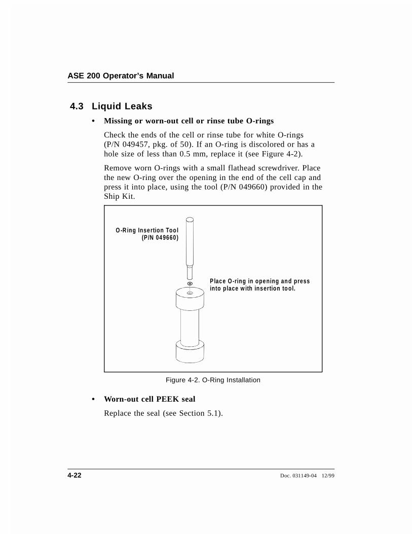
4.3 Liquid Leaks
• Missing or worn-out cell or rinse tube O-rings
Check the ends of the cell or rinse tube for white O-rings(P/N 049457, pkg. of 50). If an O-ring is discolored or has ahole size of less than 0.5 mm, replace it (see Figure 4-2).
Remove worn O-rings with a small flathead screwdriver. Placethe new O-ring over the opening in the end of the cell cap andpress it into place, using the tool (P/N 049660) provided in theShip Kit.
• Worn-out cell PEEK seal
Replace the seal (see Section 5.1).
O -R ing Insertion Too l(P/N 049660)
P lace O-ring in opening an d pressinto place w ith insertion tool.
Figure 4-2. O-Ring Installation
ASE 200 Operator’s Manual
4-22 Doc. 031149-04 12/99
• Leak in solvent flow path
Open the left-side panel door and visually inspect the followingfittings for leaks (see Figure 4-3): pump check valves, pumpfittings, solvent line fittings, transducer fittings, relief valvefittings, and static valve fittings. Tighten or replace any leakingfittings (see Section 5.2).
If the pump head is leaking, replace the piston seals (see Section5.4).
To NSupply
2
To Vent onRear Panel
To Vent onRear Panel
Figure 4-3. Solvent Flow Schematic
4 • Troubleshooting
Doc. 031149-04 12/99 4-23

• Leaking into waste vial during static cycle
Fluid dripping into the waste vial when the cell is under pressureand the static valve is closed indicates a dirty or worn reliefvalve (see Section 5.5).
• Leaking into collection vial during static cycle
Check the source needle tip in the collection vial. This is theslightly longer needle, closest to the rear of the ASE. Fluiddripping into the collection vial from the source needle duringthe static cycle indicates a dirty or worn static valve (seeSection 5.6).
4.4 Gas/Air LeaksGas/air leaks are usually audible and frequently cause excessivegas/air consumption.
Look for leaks at the air/gas supply, the rear panel, the solventreservoir compartment, and the interior connections. Open theleft-side panel door for access to the interior connections. Listen forleaks and/or run your hand over the area to feel the escaping gas.
If you find any loose connections, push the tubing firmly onto itsfitting. If the fitting or tubing continues to leak, replace it.
Do not open the door while running an extraction.
ASE 200 Operator’s Manual
4-24 Doc. 031149-04 12/99

4.5 Reports Do Not Print
• Printer connections incorrect
Display the COMMUNICATIONS screen (press Menu and 6). Movethe cursor to the COMM PORT TEST entry field and press Enter.The following test line should print:
The quick brown fox jumps over the lazy dog’s back. 0123456789
If the test line does not print, check the printer connections (seeSection 4. ). Verify that the printer port is a serial port (or that aparallel-serial converter is installed, if you are trying to printfrom a parallel printer). If the connections are correct, refer tothe printer manual for troubleshooting information.
• Automatic printout option set to off
Set the AUTOMATIC PRINTOUT field on the COMMUNICATIONS screento on.
• Attempting to print after starting the next run
Because information about the previous run is cleared frommemory when the next run starts, you must print the reportbefore starting the next run.
4 • Troubleshooting
Doc. 031149-04 12/99 4-25

ASE 200 Operator’s Manual
4-26 Doc. 031149-04 12/99
5 • Service
This chapter describes routine service procedures for the ASE 200that users may perform. Any service procedure not described heremust be performed by Dionex personnel.
NOTESThe ASE 200 electronics are not customer-serviceable. All repairsinvolving electronics components must be performed by Dionexpersonnel.
The CPU card contains a lithium battery. If the CPU card isreplaced, dispose of the used battery according to themanufacturer’s instructions.
Before replacing any part, refer to the troubleshooting information inChapter 4 to isolate the cause of the problem. When orderingreplacement parts, please include the ASE 200 model number andserial number. To contact Dionex in the U.S., call 1-800-346-6390.Outside the U.S., call the nearest Dionex office.
Substituting non-Dionex parts may impair ASE 200 performance,thereby voiding the product warranty. See the warranty statement inthe Dionex Terms and Conditions for more information.
Doc. 031149-04 12/99 5-1

5.1 Replacing the Cell PEEK Seal and Teflon O-Ring
A worn PEEK seal is deeply grooved and fails to form a tight sealbetween the cell cap and body during extractions, causing leaks.
Refer to Figure 5-1 for cell assembly components and part numbers.
1. Unscrew the cap from the cell body.
2. Use the snap ring tool (P/N 049493) provided in the Ship Kit toremove the snap ring from the cell cap. Insert the pointed endsof the tool into the two holes in the snap ring and squeeze thehandles of the tool together to release the tension on the ring.While continuing to squeeze the handles, pull the ring out of thecap. When it is out, carefully release the handles of the tool andremove the ring from the tool.
3. Remove the cap insert. Also remove the PEEK seal, which fitsinto a groove in the bottom of the insert.
Cell Body(P/N 054973, 1 mLP/N 054974, 5 mLP/N 048820, 11 mLP/N 048821, 22 mLP/N 048822, 33mL)
Snap Ring(P/N 049456, Pkg. 10)
Cap Insert
PEEK Seal(P/N 049454, Pkg. 50,P/N 049455, Pkg. 10)
End Cap(P/N 049450, Pkg. 2)(includes filters and seals)
O-Ring(P/N 049457, Pkg. 50)
Cell End Cap Assembly(P/N 049450, Pkg. 2)
Stainless Steel Frit(P/N 049453, Pkg. 50)
Figure 5-1. Cell Assembly
ASE 200 Operator’s Manual
5-2 Doc. 031149-04 12/99
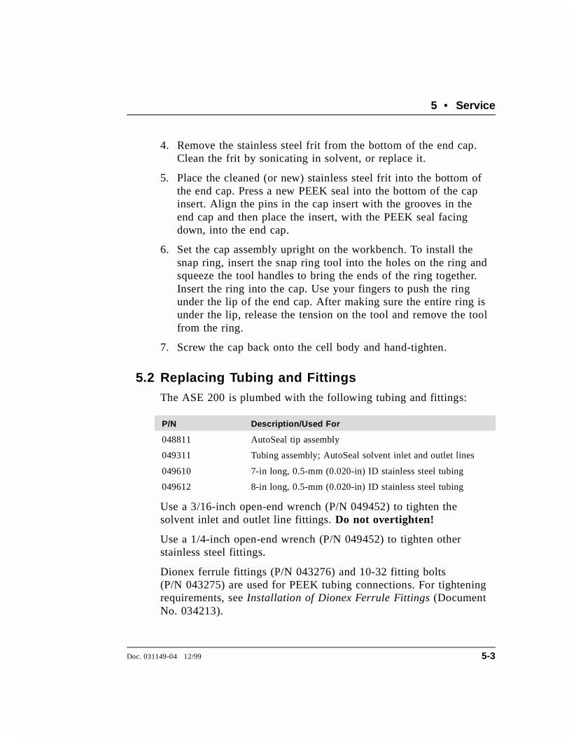
4. Remove the stainless steel frit from the bottom of the end cap.Clean the frit by sonicating in solvent, or replace it.
5. Place the cleaned (or new) stainless steel frit into the bottom ofthe end cap. Press a new PEEK seal into the bottom of the capinsert. Align the pins in the cap insert with the grooves in theend cap and then place the insert, with the PEEK seal facingdown, into the end cap.
6. Set the cap assembly upright on the workbench. To install thesnap ring, insert the snap ring tool into the holes on the ring andsqueeze the tool handles to bring the ends of the ring together.Insert the ring into the cap. Use your fingers to push the ringunder the lip of the end cap. After making sure the entire ring isunder the lip, release the tension on the tool and remove the toolfrom the ring.
7. Screw the cap back onto the cell body and hand-tighten.
5.2 Replacing Tubing and FittingsThe ASE 200 is plumbed with the following tubing and fittings:
P/N Description/Used For
048811 AutoSeal tip assembly
049311 Tubing assembly; AutoSeal solvent inlet and outlet lines
049610 7-in long, 0.5-mm (0.020-in) ID stainless steel tubing
049612 8-in long, 0.5-mm (0.020-in) ID stainless steel tubing
Use a 3/16-inch open-end wrench (P/N 049452) to tighten thesolvent inlet and outlet line fittings. Do not overtighten!
Use a 1/4-inch open-end wrench (P/N 049452) to tighten otherstainless steel fittings.
Dionex ferrule fittings (P/N 043276) and 10-32 fitting bolts(P/N 043275) are used for PEEK tubing connections. For tighteningrequirements, see Installation of Dionex Ferrule Fittings (DocumentNo. 034213).
5 • Service
Doc. 031149-04 12/99 5-3
5.3 Cleaning and/or Replacing Pump Check Valves
A dirty or worn check valve causes an erratic pump flow rate, whichprevents the pump from delivering the expected volume of solvent.
Removing the Pump
1. Turn off the power switch.
2. Open the left-side panel door. Disconnect the red and blue tubingfrom the two black elbow press fittings on top of the pump.
3. Use a 1/4-inch wrench to disconnect the stainless steel fittingfrom the outlet check valve (see Figure 5-2).
4. Disconnect the Teflon fitting from the inlet check valve.
5. Disconnect the gray cable from the pump to the J8 connector onthe valve driver card.
6. Loosen (but do not remove) the six Phillips screws that securethe component panel to the door.
7. Tip the panel upright. On the back of the panel, loosen the twoscrews that attach the pump to the panel. Slide the pump up andremove it from the panel.
Removing the Inlet Check Valve
1. Use a 1/2-inch wrench to loosen the check valve housing.Remove the housing, and then remove the check valve cartridgefrom the housing.
Removing the Outlet Check Valve
1. Turn the pump over, so that the outlet check valve is facing down.
2. Use a 1/2-inch wrench to loosen the check valve housing.Remove the housing, and then remove the check valve cartridgefrom the housing.
ASE 200 Operator’s Manual
5-4 Doc. 031149-04 12/99

Cleaning the Check Valves
1. Place the check valve housings and cartridges in a beaker withmethanol. Sonicate or agitate for several minutes.
2. Rinse each check valve housing and cartridge thoroughly withfiltered, deionized water.
Replacing the Inlet Check Valve
1. The inlet check valve assembly housing has a 1/4-28 port (thelarger port). Replace the cartridge in the inlet check valvehousing so that the double-hole end of the cartridge is visible.Liquid flows through the check valve in the large single hole andout the small double holes.
Figure 5-2. Pump Check Valves
5 • Service
Doc. 031149-04 12/99 5-5

2. Reinstall the check valve. Tighten just enough to seat (25 in-lbtorque). Tighten a little more only if it leaks.
Overtightening may damage the pump head and the checkvalve housing and crush the check valve seats.
Replacing the Outlet Check Valve
1. The outlet check valve assembly housing has a 10-32 port (thesmaller port). Replace the cartridge in the outlet check valvehousing so that the single-hole end of the cartridge is visible.Liquid flows through the check valve in the large single hole andout the small double holes.
2. With the pump still inverted, reinstall the check valve. Tightenjust enough to seat (25 in-lb torque). Tighten a little more only ifit leaks.
Overtightening may damage the pump head and the checkvalve housing and crush the check valve seats.
Reinstalling the Pump
1. Reinstall the pump on the component panel.
2. Reattach the component panel to the left-side panel door.
3. Reconnect the two air lines to the press fittings on the top of thepump.
4. Reconnect the solvent lines to the inlet and outlet check valvehousings.
5. Reconnect the electrical connector to J6 on the valve driver card.
ASE 200 Operator’s Manual
5-6 Doc. 031149-04 12/99
Completing the Procedure
1. Turn on the power switch.
2. Rinse the system (see Section B.2.9). If the system will not rinseand all other possible causes of the problem have beeneliminated, replace the check valve cartridges (P/N 047755).
5.4 Replacing Piston Seals
Leaking from the pump head indicates that the piston seal and pistonrinse seal should be replaced.
Removing the Pump
1. Turn off the power switch.
2. Open the left-side panel door. Disconnect the red and blue tubingfrom the two black elbow press fittings on top of the pump.
3. Use a 1/4-inch wrench to disconnect the stainless steel fittingfrom the outlet check valve (see Figure 5-2).
4. Disconnect the Teflon fitting from the inlet check.
5. Disconnect the gray cable from the pump to the J8 connector onthe valve driver card.
6. Loosen (but do not remove) the six Phillips screws that securethe component panel to the door.
7. Tip the panel upright. On the back of the panel, loosen the twoscrews that attach the pump to the panel. Slide the pump up andremove it from the panel.
5 • Service
Doc. 031149-04 12/99 5-7
Replacing the Piston Seal
1. Using a 7 mm nut driver or wrench, loosen and remove the twonuts securing the pump head to the body.
2. Slide the pump head off the bolts.
3. Locate the piston seal (orange with a white internal ring) behindthe tan piston guide in the pump head.
4. Insert the new piston seal (P/N 047583), with the white ring facedown, into the pump head.
5. Reinstall the pump head into the pump body.
Replacing the Piston Rinse Seal
1. Remove the black cover from the side of the pump.
2. Remove the small electronics card from the side of the pump.
3. Using a 7 mm nut driver or wrench, loosen and remove the nutsfrom the ends of the bolts that secure the end plates to the pumpbody.
4. Remove the left end plate from the pump cylinder, exposing thepiston.
5. Remove the piston rinse seal from the left end plate. The rinseseal is orange, as is the piston seal, but does not contain a whitering.
6. Insert the new piston rinse seal (P/N 048722), with the closedend facing down, into the end plate. Gently press the seal intoplace with a cotton-tipped swab (or other tool with a soft tip).
7. Verify that the piston rinse seal was properly installed by slidingthe piston backwards through the hole. If the seal sticks to thepiston and comes out of the left end plate, it was not installedfirmly enough. Gently press the seal into place.
8. Secure the pump cylinder to the end plates and tighten the bolts.
ASE 200 Operator’s Manual
5-8 Doc. 031149-04 12/99

9. Reattach the electronics card to the side of the pump and replacethe black cover.
Reinstalling the Pump
1. Reinstall the pump on the component panel.
2. Reattach the component panel to the left-side panel door.
3. Reconnect the two air lines to the press fittings on the top of thepump.
4. Reconnect the solvent lines to the inlet and outlet check valvehousings.
5. Reconnect the electrical connector to J6 on the valve driver card.
6. Turn on the power switch.
5 • Service
Doc. 031149-04 12/99 5-9
5.5 Replacing the Pressure Relief Valve
Leaking into the waste vial when the pressure relief valve is closedindicates a dirty or worn valve.
1. Turn off the power switch.
2. Open the left-side panel door.
3. The relief valve (P/N 048889) is installed directly above thepump on the component panel. Disconnect the green tubing fromthe elbow press fitting on the valve.
4. Disconnect the stainless steel line from the left side of the valve.This tubing connects to the transducer.
5. Disconnect the stainless steel line from the right side of thevalve. This tubing connects to the upper AutoSeal arm.
6. Disconnect the green PEEK waste line.
7. Loosen the two screws on the bracket that secures the valve tothe panel. Slip the screws through the keyholes on the bracketand remove the valve.
8. Install the new valve on the bracket and tighten the screws.Reconnect all of the lines.
ASE 200 Operator’s Manual
5-10 Doc. 031149-04 12/99

5.6 Replacing the Static Valve
Leaking from the source needle into the collection vial when thestatic valve is closed indicates a dirty or worn valve.
1. Turn off the power switch.
2. Open the left-side panel door.
3. The static valve (P/N 048778) is installed on the rear of theneedle mechanism. Disconnect the two stainless steel lines fromthe valve.
4. Disconnect the orange tubing from the elbow press fitting on thevalve.
5. Loosen the two screws on the bracket that secures the valve tothe needle mechanism. Slip the screws through the keyholes onthe bracket and remove the valve.
6. Install the new valve on the bracket and tighten the screws.Reconnect all of the lines.
5 • Service
Doc. 031149-04 12/99 5-11

5.7 Replacing Needles
5.7.1 Vent Needle
1. Turn off the power switch.
2. Open the left-side panel door and locate the needleassembly on the inside wall of the ASE 200.
3. Remove the vial needle cover. To do this, use a Phillipsscrewdriver to loosen the two screws located on the backof the needle mechanism (see Figure 5-3). Pull the needlemechanism to the left toward the back of the instrument.Lift the cover up and off. Push the mechanism backtoward the vial tray.
Figure 5-3. Rear View of Needle Mechanism
ASE 200 Operator’s Manual
5-12 Doc. 031149-04 12/99
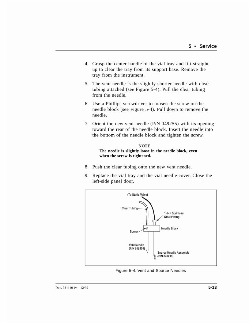
4. Grasp the center handle of the vial tray and lift straightup to clear the tray from its support base. Remove thetray from the instrument.
5. The vent needle is the slightly shorter needle with cleartubing attached (see Figure 5-4). Pull the clear tubingfrom the needle.
6. Use a Phillips screwdriver to loosen the screw on theneedle block (see Figure 5-4). Pull down to remove theneedle.
7. Orient the new vent needle (P/N 049255) with its openingtoward the rear of the needle block. Insert the needle intothe bottom of the needle block and tighten the screw.
NOTEThe needle is slightly loose in the needle block, evenwhen the screw is tightened.
8. Push the clear tubing onto the new vent needle.
9. Replace the vial tray and the vial needle cover. Close theleft-side panel door.
Figure 5-4. Vent and Source Needles
5 • Service
Doc. 031149-04 12/99 5-13
5.7.2 Source Needle
1. Turn off the power switch.
2. Open the left-side panel door and locate the needleassembly on the inside wall of the ASE 200.
3. Remove the vial needle cover. To do this, use a Phillipsscrewdriver to loosen the two screws located on the backof the needle assembly (see Figure 5-3). Pull the needleassembly to the left, toward the back of the instrument.Lift the cover up and off. Push the assembly back towardthe vial tray.
4. Use a 1/4-inch open-end wrench to disconnect thestainless steel fitting on the left side of the static valve.
5. From the right side of the ASE 200, disconnect the1/4-inch stainless steel fitting from the needle block (seeFigure 5-4).
6. Pull the needle assembly to the left, toward the back ofthe instrument, and remove the source needle.
7. Orient the new source needle assembly (P/N 049219) withthe opening toward the front of the needle block. Insertthe needle into the needle block from the top.
8. Replace the stainless steel tubing and fittings on the staticvalve and the needle block.
9. Replace the vial needle cover and close the left-side door.
ASE 200 Operator’s Manual
5-14 Doc. 031149-04 12/99

5.8 Changing the Main Power Fuses
1. Turn off the main power.
HIGH VOLTAGE—Disconnect the main power cord from itssource and also from the rear panel of the ASE 200.
2. The fuse holder is part of the main power receptacle on the rearpanel. A recessed lock is located on each side of the fuse holder(see Figure 5-5). Using a small screwdriver or your fingernails,push each lock toward the center to release it. The fuse holderpops out approximately 0.16 cm (1⁄16 inch) when the locksrelease. When both locks are released, pull the fuse holderstraight out of its compartment.
3. The holder contains two fuses. Replace these with new IEC127fast-blow fuses rated 3.15 amps (P/N 954745). Dionexrecommends replacing both fuses even though only one is open;the other fuse has been stressed and could fail even under normaloperation.
Fuse Holder
Fuse Holder(Side View)
Fuses (2)
Insertsc re w driverand tw ist torelea se(e ach side)
Lock ingS pring
LockingSpring
Main Pow erReceptacle
K e y
Figure 5-5. Main Power Fuse Holder
5 • Service
Doc. 031149-04 12/99 5-15

4. Reinsert the fuse holder into its compartment. The fuse holder iskeyed to fit only in its proper orientation. Apply sufficientpressure evenly against the holder to engage the two locks. Theholder is flush against the panel when both locks are engaged.
5. Reconnect the main power cord and turn on the power.
5.9 Calibrating the Hydrocarbon SensorWhen the hydrocarbon sensor reading is low and the sensor needs tobe calibrated, an on-screen error message is displayed.
1. Open the HYDROCARBON CALIBRATION screen (option 4 on theDIAGNOSTIC MENU).
2. Open the front panel door and swing it toward the cell carousel.
3. Remove the rear cover of the ASE 200.
The motor driver card (labeled Tray MTR/AS) is on the rearpanel, above the fan. The hydrocarbon sensor is plugged intoposition J14 on the card. The R1 potentiometer (pot) is locatedimmediately to the left of the sensor.
Figure 5-6. Accessing the Hydrocarbon Sensor
ASE 200 Operator’s Manual
5-16 Doc. 031149-04 12/99

4. Stand behind the ASE 200 in a location from which you canclearly see the HYDROCARBON CALIBRATION screen (see Figure5-6).
5. Turning the R1 pot clockwise decreases the value; turning itcounterclockwise increases the value. Using a small flatheadscrewdriver or a trimmer adjuster (P/N 035617), begin adjustingthe R1 pot (see Figure 5-7). When the ACTUAL SENSOR READING
is set to 4000, press Enter to calibrate the UPPER VAPOR
THRESHOLD.
6. Reinstall the rear cover and wait for the sensor to equilibrate.After equilibration, the UPPER VAPOR THRESHOLD reading shouldbe 9500 ± 2000. If it is not, carefully insert the screwdriver ortrimmer adjuster tool through the hole on the rear cover andadjust the pot again.
NOTEFailure to replace the rear cover invalidates the sensor testin the next step.
Figure 5-7. Adjusting the R1 Potentiometer
5 • Service
Doc. 031149-04 12/99 5-17

7. Hold an open solvent vial in the service compartment, near therear panel, and verify that the ACTUAL SENSOR READING rises.Next, remove the solvent vial and verify that the ACTUAL SENSOR
READING drops.
• If the readings rise and fall correctly, the sensor isoperating correctly. Resume routine operation.
• If the readings do not rise and fall correctly, the sensor isdefective and must be replaced. Refer to Section 5.10 forinstructions.
5.10 Replacing the Hydrocarbon Sensor1. Turn off the main power.
2. Remove the rear cover of the ASE 200.
3. The motor driver card (labeled Tray MTR/AS) is on the rearpanel, above the fan. Locate the hydrocarbon sensor in positionJ14 of the card. Unplug the sensor by pulling it straight awayfrom the board.
NOTEDionex recommends wearing latex gloves when handling the newhydrocarbon sensor.
4. The new sensor (P/N 938918) has only four prongs, although thesensor socket has six holes. Plug the sensor into the four holesindicated in Figure 5-8.
5. Replace the rear cover.
6. Turn on the main power.
7. Dionex recommends burning in the sensor overnight. If this isnot possible, wait at least 2 hours for the signal to stabilizebefore resuming operation.
ASE 200 Operator’s Manual
5-18 Doc. 031149-04 12/99
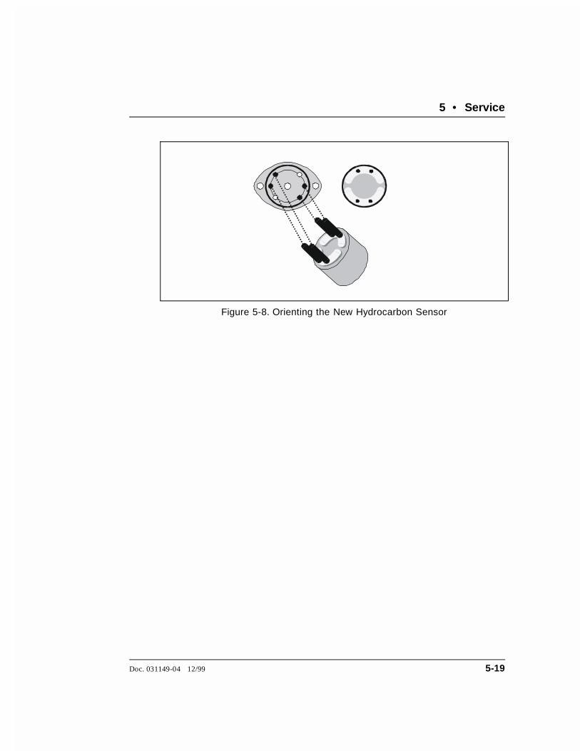
Figure 5-8. Orienting the New Hydrocarbon Sensor
5 • Service
Doc. 031149-04 12/99 5-19

ASE 200 Operator’s Manual
5-20 Doc. 031149-04 12/99

A • Specifications
A.1 Electrical
Main PowerRequirements
90 to 260 Vac, 50/60 Hz; less than 5 amps at 120 Vac. TheASE 200 main power supply is auto-sensing and requires novoltage adjustment.
Oven PowerRequirements
Switch for selecting the heater voltage range: 90 to 130 Vac,or 220 to 260 Vac
FuseRequirements
Two IEC127 fast-blow fuses rated 3.15 amps (P/N 954745)
A.2 Environmental
OperatingTemperature
10 to 40 °C (50 to 104 °F)
OperatingHumidity
5 to 95% relative humidity, noncondensing
Decibel Level 64 db (at “A WEIGHING” setting)
A.3 Physical
Dimensions 59.4 cm high x 58.8 cm wide x 60.4 cm deep(23.4 in x 23.1 in x 23.8 in)
Weight 71.6 kg (156 lb)
A.4 Pneumatic
Laboratory Air 0.41 to 1.38 MPa (60 to 200 psi)
Nitrogen 0.97 to 1.38 MPa (140 to 200 psi)
Doc. 031149-04 12/99 A-1
A.5 Display and Keypad
Display Liquid crystal with adjustable backlighting and contrast
Keypad 26-button keypad for entering commands and programmingmethods and schedules
A.6 Extraction Cells and Tray
ExtractionCells
Stainless steel cell and caps with PEEK seals and stainlesssteel frits. Five cell capacities available.
Cell Capacity Internal Cell Diameter
1 mL 5.8 mm (0.23 in)5 mL 12.94 mm (0.52 in)11 mL 19.1 mm (0.76 in)22 mL 19.1 mm (0.76 in)33 mL 19.1 mm (0.76 in)
Cell Tray 24 sample cell positions and four rinse positions. Trayaccommodates any combination of cell sizes.
A.7 Collection Vials and Trays
Collection Vials Three sizes: 40 mL, 40 mL graduated, and 60 mL. Vial septaare Teflon-coated on the solvent side.
Vial Trays Removable tray accommodates 40 mL and 60 mL vials. Trayinserts adapt tray for standard 40 mL vials; vial spacers adapttray for 40 mL graduated vials. Twenty-six collection vialpositions and four rinse positions.
A.8 Interior Components
Oven Heats to 200 °C. Accommodates one cell at a time in avertical position. Shuts off automatically after four hours ofsystem inactivity.
Pump Operating pressure from 3.45 MPa to 20.7 MPa (500 psi to3000 psi)
ASE 200 Operator’s Manual
A-2 Doc. 031149-04 12/99

Valves High pressure valves: purge, pressure relief, and static
Vial Sensors Sensors for detecting vial present, vial containingapproximately 1 mL, and full vial
Leak Sensors Hydrocarbon vapor and liquid level
A • Specifications
Doc. 031149-04 12/99 A-3

ASE 200 Operator’s Manual
A-4 Doc. 031149-04 12/99

B • Installation
B.1 Facility Requirements
Provide the following installation site facilities for the ASE 200:
• A sturdy table or workbench with enough free space behind theASE 200 for connections and ventilation.
Use caution when lifting the ASE 200. Two or more personsshould lift the module, which weighs 71.6 kg (156 lb). Liftonly from the bottom or side surfaces; lifting with the paneldoors will damage the door hinges.
• A source of laboratory compressed air, regulated to between 0.41and 1.38 MPa (60 and 200 psi); 0.68 MPa (100 psi) isrecommended. If compressed air is unavailable, substitutenitrogen (see Section B.2.1).
To avoid contamination and possible deterioration of thepump and air valve seals, make sure laboratory compressedair is oil-free, dry, and filtered, and maintained within thepressure limits specified above.
• A source of 99.9% pure nitrogen gas, regulated to between 0.97and 1.38 MPa (140 and 200 psi); 1.03 MPa (150 psi) isrecommended. UHP (ultra-high purity) gas may be required forapplications using a very clean baseline electron capture detector(ECD).
• A power source of 90 to 260 Vac; 50/60 Hz. For operation of theoven, set a switch to select either the low voltage range (90 to130 Vac) or high voltage range (220 to 260 Vac) (see page B-6).
• A printer with an RS-232 serial interface (optional).
Doc. 031149-04 12/99 B-1

B.2 Installation Instructions
The ASE 200 Ship Kit (P/N 049009) contains all of the itemsneeded to install the instrument.
B.2.1 Air/Nitrogen Connections
NOTEThis section describes two installation procedures. Thefirst procedure explains how to connect compressed airand nitrogen gas sources to the ASE 200. The secondprocedure explains how to configure the system whencompressed air is not available.
Compressed Air and Nitrogen Connections
NOTEThe air and nitrogen connections are press fittings. Toconnect a press fitting, firmly push the tubing into thefitting until it is seated. To disconnect a press fitting, useyour fingers (or a small open-end wrench) to press the ringon the fitting in, while pulling the tubing out.
1. Connect the 6-mm (0.25-in) elbow fitting (P/N 214738) tothe regulator on the compressed air source.
2. Push one end of the yellow 6-mm (0.25-in) OD tubing(P/N 214739) into the elbow fitting and connect the inletfilter assembly (P/N 049492) to the other end of thetubing. Check that the arrow on the filter points in thedirection of the air flow (toward the ASE 200). Push thetubing on the other end of the filter assembly into the AIR
connector on the ASE 200 rear panel (see Figure B-1).
Do not obstruct or pressurize the vent outlet.
ASE 200 Operator’s Manual
B-2 Doc. 031149-04 12/99

Make sure the vent tubing runs downhill from the ASE 200rear panel. This prevents formation of a trap, which wouldprevent vapors from being vented through the tubing.
3. Adjust the compressed air pressure source to between0.69 and 1.38 MPa (100 and 200 psi); 0.69 MPa (100 psi)is recommended.
4. Connect the 4-mm (0.156-in) elbow fitting (P/N 049272)to the regulator on the nitrogen gas source. Push one endof the blue 4-mm (0.156-in) OD tubing (P/N 049296) intothe elbow fitting; push the other end into the NITROGEN
connector on the rear panel.
8-m m (0.312-in) ODClear Tubing (P/N 053514)
6-m m (0.25-in) OD Yellow Tubing (P/N 214739)
4-m m (0.156-in) ODBlue Tubing (P/N 049296)
0.97 to 1.38 MPa(140 to 200 psi)
0.41 to 1.38 MPa(60 to 200 psi)
ASE 200 Rear Panel 6-m m (0.25-in) Elbow Fitting (P/N 214738)
4-m m (0.156-in) Elbow Fitting(P/N 049272)
In let F ilter A ssem bly(P/N 049492)
Power Cord
AIR
N2
AuxAir
NitrogenVent
WARNING! Do not obstruct or pressurize the vent outlet.
Figure B-1. Rear Panel Connections
B • Installation
Doc. 031149-04 12/99 B-3

5. Push one end of the 10-ft section of clear 8-mm(0.312-in) OD tubing (P/N 053514) into the VENT
connector on the rear panel. Route the tubing to a venthood, if desired.
6. Adjust the nitrogen pressure source to between 0.97 and1.38 MPa (140 and 200 psi); 1.03 MPa (150 psi) isrecommended.
Substituting Nitrogen for Compressed Air
This section describes how to connect the nitrogen gas sourceto the NITROGEN and AIR connectors on the ASE 200 rearpanel.
NOTEThe nitrogen connections are press fittings. To connect apress fitting, firmly push the tubing into the fitting untilit is seated. To disconnect a press fitting, use your fingers(or a small open-end wrench) to press the ring on thefitting in, while pulling the tubing out.
1. Connect the yellow 6-mm (0.25-in) OD tubing end of thetee assembly to the AIR connector on the ASE 200 rearpanel (see Figure B-2).
2. Connect the blue 4-mm (0.156-in) OD tubing end of thetee assembly to the NITROGEN connector on the rear panel.
3. Wrap Teflon tape around the threads of the 6-mm(0.25-in) elbow fitting (P/N 214738) and then connect thefitting to the regulator on the nitrogen gas source. Pushone end of the yellow 6-mm (0.25-in) OD tubing(P/N 214739) into the elbow fitting; push the other endinto the fitting on the tee assembly.
ASE 200 Operator’s Manual
B-4 Doc. 031149-04 12/99

B.2.2 Electrical Connections
1. Connect a modular power cord (IEC 320 C13) from thepower receptacle on the rear panel to a grounded,single-phase power source of 90 to 260 Vac and 50/60 Hz.
SHOCK HAZARD—To avoid electrical shock, a groundedreceptacle must be used. Do not operate or connect to ACpower mains without an earthed ground connection.
The power cord is used as the main disconnect device.Make sure the power source outlet is located near the ASE200 and is easily accessible.
Operation at AC input levels outside the specified operatingvoltage range may damage the ASE 200.
6-m m (0.25-in) O D Yellow Tubing(P/N 214739)
Connect to nitrogen source0.97 to 1.38 M Pa(140 to 200 psi)6-m m (0.25-in) O D Yellow Tubing
(P/N 214739)
6-m m (0.25-in) E lbow Fitting(P/N 214738)
4-m m (0.156-in) OD Blue Tubing(P/N 049296)
Air/Nitrogen Tee A ssem bly(P/N 049680)
Inle t Filter Assem bly(P/N 049492)Aux
Rear PanelConnectors
Air
Nitrogen
Vent
WARNING! Do not obstruct or pressurize the vent outlet.
Figure B-2. Connections for Substituting Nitrogen for Air
B • Installation
Doc. 031149-04 12/99 B-5
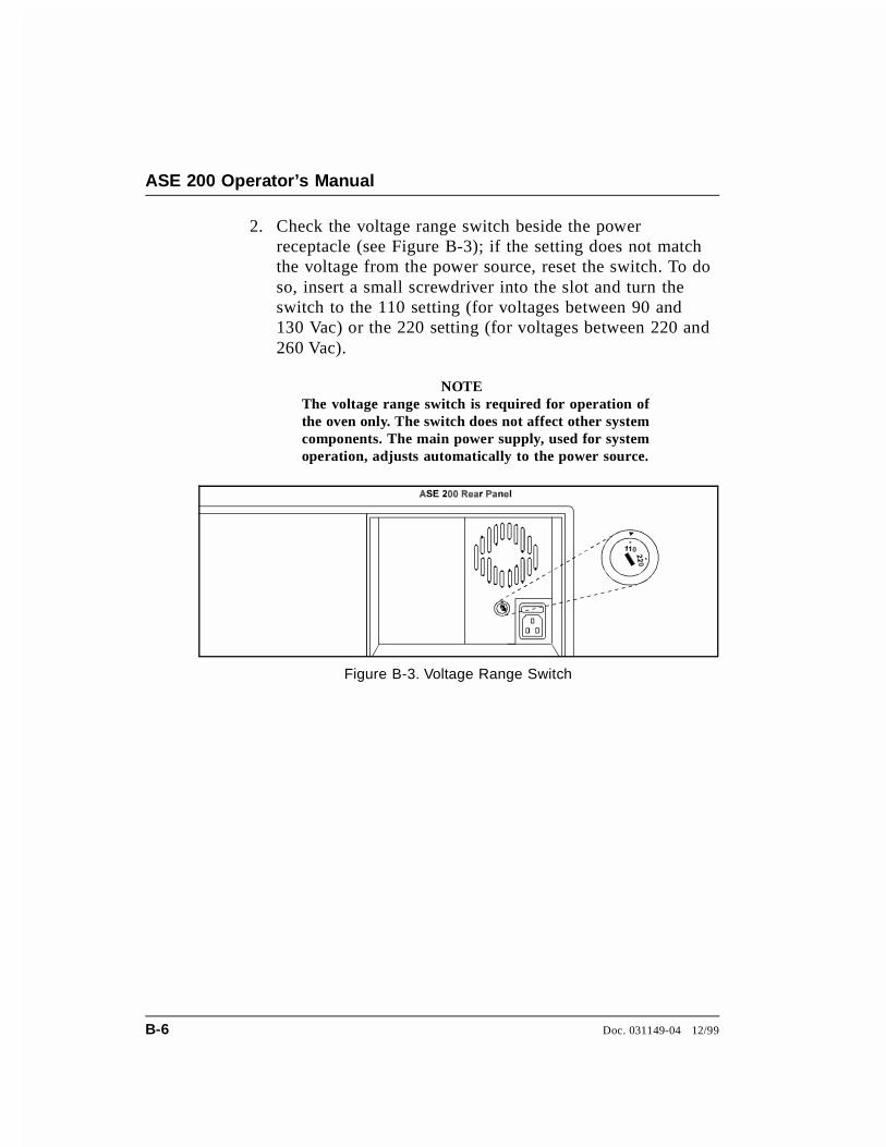
2. Check the voltage range switch beside the powerreceptacle (see Figure B-3); if the setting does not matchthe voltage from the power source, reset the switch. To doso, insert a small screwdriver into the slot and turn theswitch to the 110 setting (for voltages between 90 and130 Vac) or the 220 setting (for voltages between 220 and260 Vac).
NOTEThe voltage range switch is required for operation ofthe oven only. The switch does not affect other systemcomponents. The main power supply, used for systemoperation, adjusts automatically to the power source.
Figure B-3. Voltage Range Switch
ASE 200 Operator’s Manual
B-6 Doc. 031149-04 12/99

B.2.3 DX-LAN Network Connections (Optional)
For the ASE 200 to communicate with AutoASE software, aDX-LAN interface card must be installed in the ASE 200 anda DX-LAN cable must be connected to the rear panel. Theprocedure below explains how to install these items.
STATIC—The ASE 200 electronics cannot be serviced bythe user. The DX-LAN interface card should be installed byqualified personnel only. Be sure to observe standardanti-static procedures when installing the interface card.
To prevent damage to the ASE 200, turn off the main powerbefore install ing the DX-LAN interface card. Afterconfirming that the LED on the CPU card is off (not greenor red), unplug the power cord from the mains. Do not relyon the front panel power switch.
1. Open the ASE 200 upper front door. Remove theTTL/Relay plugs from the connectors at slot 4 (the SPcard) of the electronics chassis. (The label on the insideof the front door identifies the card locations.)
2. To disconnect the 60-pin ribbon cable from the frontpanel, first close the tilt panel to expose the connector andits ejector latches. Remove the cable by opening theejector latches.
3. Using a screwdriver as a lever, open the white ejectorlatch at the bottom of the CPU card. Remove the CPUcard, cable, and Relay card as a single unit.
4. Insert the DX-LAN interface card (P/N 044195) into slot4. Slide the card to the rear. Verify that the BNCconnector is aligned with the hole at the rear and that thecard is aligned with the connector. Press firmly on thecard until it mates fully with the DX-LAN connector onthe rear panel.
B • Installation
Doc. 031149-04 12/99 B-7

5. Reinstall the CPU/Relay card. Press firmly until the CPUcard is inserted into the connector on the rear panel.
6. Reconnect the ribbon cable to the 60-pin connector on thefront panel. The header and connector are key-polarizednear the center. The ejector latches should be partiallyopen to accept the cable connector.
7. If the ASE 200 is the last module in the network to beconnected, install a terminator plug (P/N 921034) on theremaining port of the BNC tee connector. (The terminatorplug is shipped with AutoASE.)
If the ASE 200 is not the last module, connect the cablefrom the next module to the BNC tee.
Terminator resistor plugs must be installed at each end ofthe DX-LAN. Verify that both ends of the DX-LAN haveresistor plugs installed.
8. Connect the DX-LAN cable (P/N 960404) to theDX-LAN connector on the rear panel.
NOTEA 15-meter (50-ft) DX-LAN extension cable (P/N 046016)is available from Dionex.
ASE 200 Operator’s Manual
B-8 Doc. 031149-04 12/99
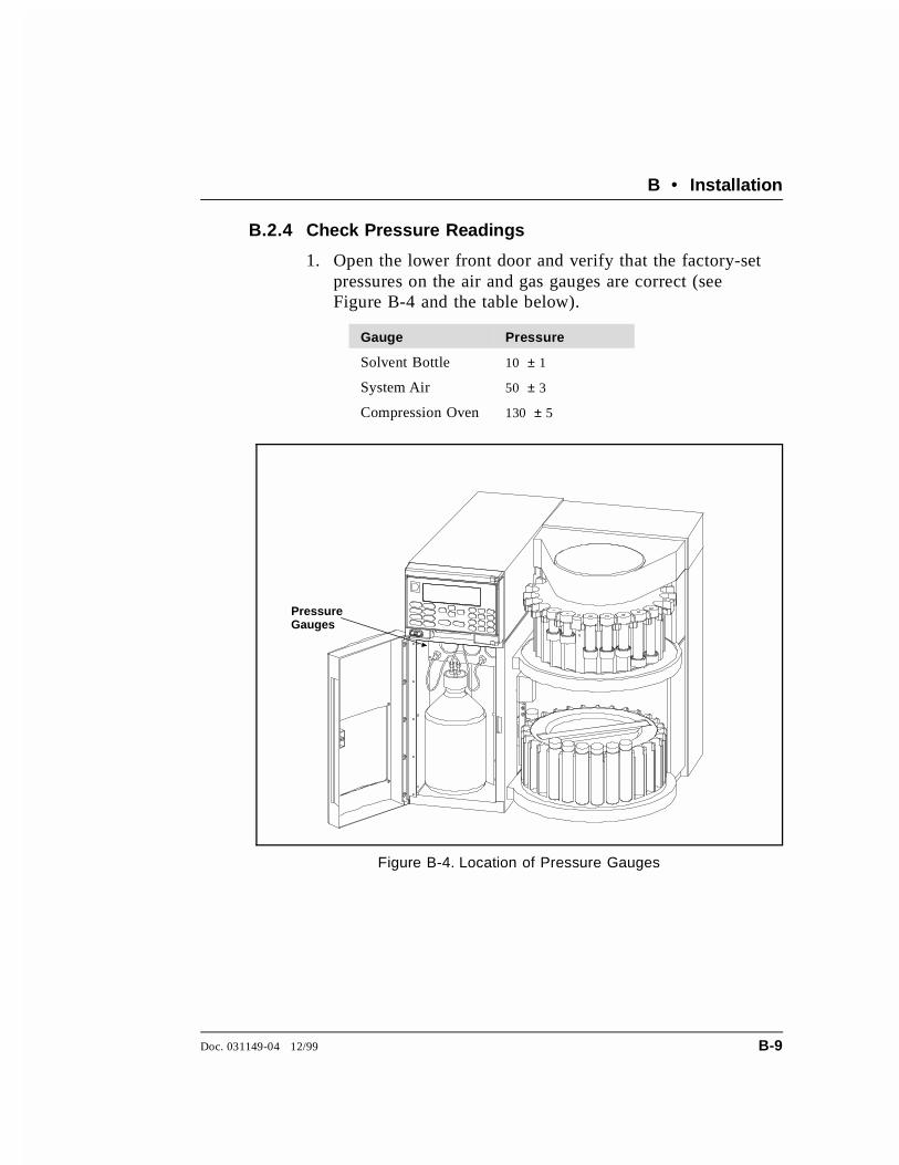
B.2.4 Check Pressure Readings
1. Open the lower front door and verify that the factory-setpressures on the air and gas gauges are correct (seeFigure B-4 and the table below).
Gauge Pressure
Solvent Bottle 10 ± 1
System Air 50 ± 3
Compression Oven 130 ± 5
Pressure Gauges
Figure B-4. Location of Pressure Gauges
B • Installation
Doc. 031149-04 12/99 B-9

2. If one or more of the pressure readings requiresadjustment, open the left-side panel door to gain access tothe regulators (see Figure B-5). The three regulator knobscorrespond to the three gauges in the solvent reservoircompartment. To adjust a pressure, pull the appropriateregulator knob out, rotate until the corresponding pressuregauge shows the correct reading, and then push the knobback in.
Figure B-5. Location of Regulators
ASE 200 Operator’s Manual
B-10 Doc. 031149-04 12/99
B.2.5 Solvent Reservoir Compartment Connections
Solvent Reservoir Connections
NOTEWhen operating with an ASE 200 Solvent Controller,disregard this section and follow the instructions inthe Solvent Controller manual.
1. Fill the solvent reservoir (P/N 045901) with a preparedsolvent, such as acetone. See Section 3.1.1 forinformation about selecting and preparing solvents.
Use only Dionex solvent reservoirs. These are glassreservoirs with a plastic, shatterproof coating. To preventoperator injury, make sure the pressure applied to thereservoirs does not exceed 0.07 MPa (10 psi).
2. Insert the outlet line extending from the underside of thereservoir cap assembly (P/N 049496) into the reservoir(see Figure B-6). Make sure that the in-line filter rests onthe bottom of the reservoir; this prevents air from beingdrawn through the line. If necessary, gently pull on theoutlet line to bring more line into the reservoir.
3. Hand-tighten the cap securely over the stopper.
4. Set the reservoir in the solvent reservoir compartment.Screw the fitting on the solvent outlet line into theconnector labeled SOLVENT at the top of the reservoircompartment (see Figure B-6).
5. Push the fitting on the gas inlet line into the connectorlabeled GAS. (To disconnect the line, push down on thesmall latch at the top of the connector and pull the fittingout.)
B • Installation
Doc. 031149-04 12/99 B-11

6. When refilling the reservoir, remove the cap and stopperand remove the reservoir from the compartment. It is notnecessary to disconnect the solvent and gas lines.
NOTEFill the reservoir only when the ASE 200 is idle. Thereservoir is pressurized during rinse cycles andsample extractions.
Figure B-6. Solvent Reservoir Assembly
ASE 200 Operator’s Manual
B-12 Doc. 031149-04 12/99

Waste Vial Installation
7. Use a 40 mL or a 60 mL collection vial for wastecollection. The waste vial installs in a holder on the rightinside wall of the solvent reservoir compartment (seeFigure B-7). The bottom bracket of the holder can beinstalled in one of two locations, depending on the size ofthe waste vial (see Figure B-7). The upper location is for40 mL vials and the lower location is for 60 mL vials. Ifnecessary, remove the two mounting screws (using a2.5-mm Allen wrench or a Phillips head screwdriver) andreattach the bracket in the correct location.
Figure B-7. Waste Bracket Mounting Locations
B • Installation
Doc. 031149-04 12/99 B-13

8. To install the vial, tilt it at about a 15° angle and align thelip of the vial with the opening under the top bracket ofthe holder (see Figure B-8, view A).
9. Push the lip of the vial up into the top bracket andstraighten the vial until it is vertical and rests on thebottom bracket (see Figure B-8, view B). To remove thevial, push it up. Then tilt it out and pull it down and awayfrom the bracket.
Figure B-8. Waste Vial Installation
ASE 200 Operator’s Manual
B-14 Doc. 031149-04 12/99
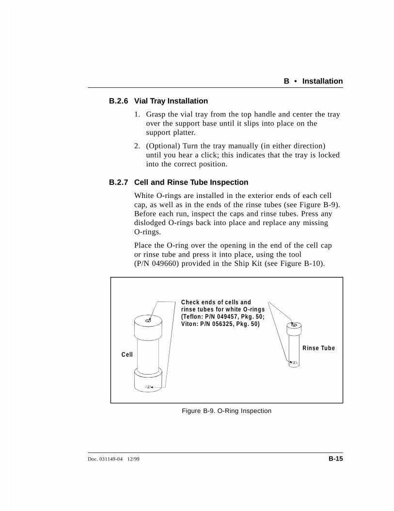
B.2.6 Vial Tray Installation
1. Grasp the vial tray from the top handle and center the trayover the support base until it slips into place on thesupport platter.
2. (Optional) Turn the tray manually (in either direction)until you hear a click; this indicates that the tray is lockedinto the correct position.
B.2.7 Cell and Rinse Tube Inspection
White O-rings are installed in the exterior ends of each cellcap, as well as in the ends of the rinse tubes (see Figure B-9).Before each run, inspect the caps and rinse tubes. Press anydislodged O-rings back into place and replace any missingO-rings.
Place the O-ring over the opening in the end of the cell capor rinse tube and press it into place, using the tool(P/N 049660) provided in the Ship Kit (see Figure B-10).
Check ends of ce lls andrinse tubes for white O-rings(Teflon: P /N 049457, Pkg. 50;Viton: P /N 056325, Pkg. 50)
CellR inse Tube
Figure B-9. O-Ring Inspection
B • Installation
Doc. 031149-04 12/99 B-15

O-Ring Insertion Tool(P/N 049660)
Place O-ring in opening and pressinto place with insertion tool.
Figure B-10. O-Ring Installation
ASE 200 Operator’s Manual
B-16 Doc. 031149-04 12/99
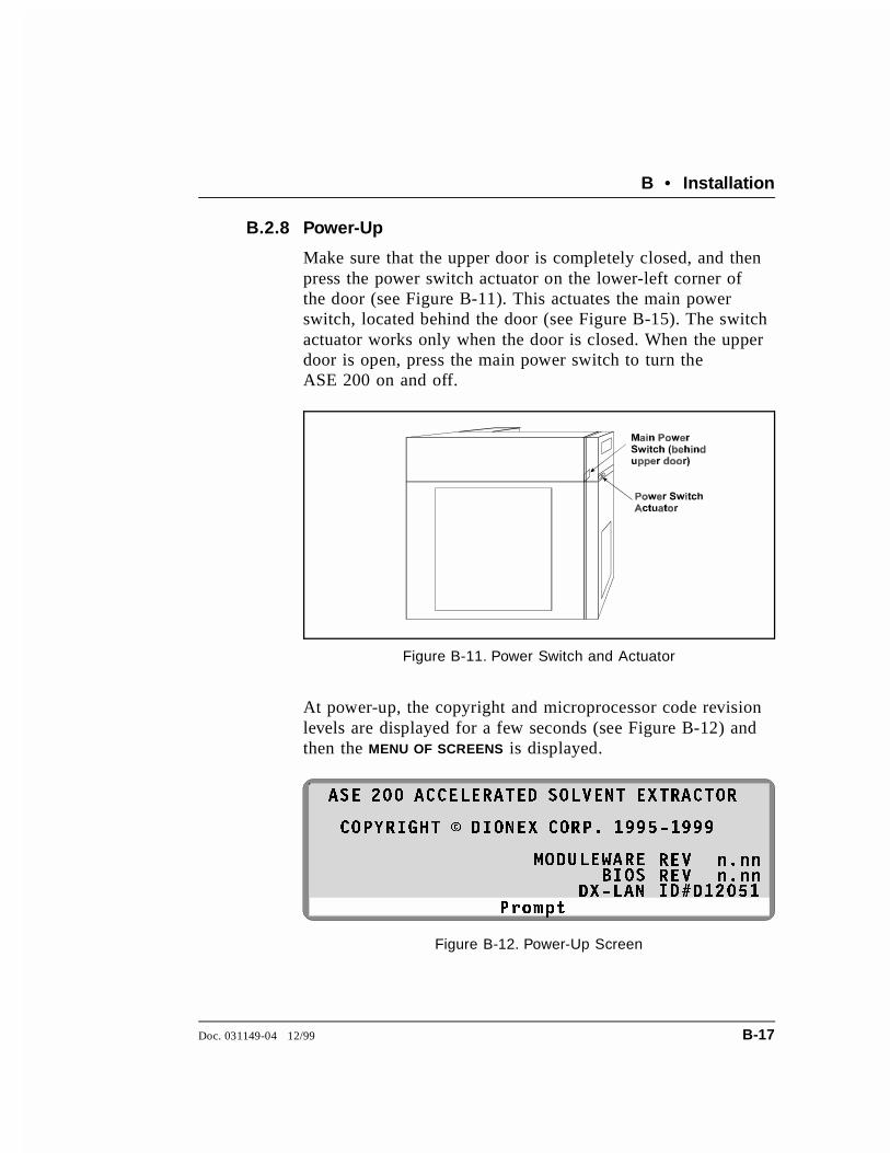
B.2.8 Power-Up
Make sure that the upper door is completely closed, and thenpress the power switch actuator on the lower-left corner ofthe door (see Figure B-11). This actuates the main powerswitch, located behind the door (see Figure B-15). The switchactuator works only when the door is closed. When the upperdoor is open, press the main power switch to turn theASE 200 on and off.
At power-up, the copyright and microprocessor code revisionlevels are displayed for a few seconds (see Figure B-12) andthen the MENU OF SCREENS is displayed.
Figure B-11. Power Switch and Actuator
3URPSW
$6( ��� $&&(/(5$7(' 62/9(17 (;75$&725
&23<5,*+7 � ',21(; &253� ���������
02'8/(:$5(
';�/$15(9,'�
Q�QQQ�QQ
'�����%,26
5(9
Figure B-12. Power-Up Screen
B • Installation
Doc. 031149-04 12/99 B-17

B.2.9 Rinsing/Priming the System
1. Place rinse tubes in the four rinse positions on the celltray (between positions 1 and 24, 6 and 7, 12 and 13, 18and 19).
2. Place collection vials in positions R1, R2, R3, and R4 inthe vial tray. To adapt the vial tray positions for regular40 mL vials, install removable inserts (P/N 049348) intothe tray positions. To adapt the tray positions forgraduated 40 mL vials, install vial spacers (P/N 055444)into the tray positions. No inserts or spacers are requiredfor the 60 mL vials.
3. Press Rinse to start a manual rinse/prime cycle. Duringthe cycle, the cell tray rotates to the nearest rinse tube,the vial tray rotates to a rinse position, and approximately4 mL of solvent is pumped through the system.
To avoid personal injury, exercise caution when the tray isin motion.
4. Press Rinse again. After the second rinse, the pump andthe solvent line are primed.
ASE 200 Operator’s Manual
B-18 Doc. 031149-04 12/99
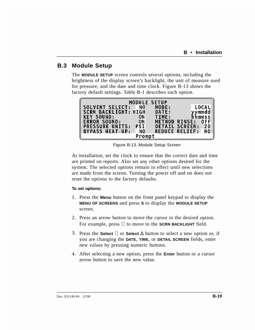
B.3 Module Setup
The MODULE SETUP screen controls several options, including thebrightness of the display screen’s backlight, the unit of measure usedfor pressure, and the date and time clock. Figure B-13 shows thefactory default settings. Table B-1 describes each option.
At installation, set the clock to ensure that the correct date and timeare printed on reports. Also set any other options desired for thesystem. The selected options remain in effect until new selectionsare made from the screen. Turning the power off and on does notreset the options to the factory defaults.
To set options:
1. Press the Menu button on the front panel keypad to display theMENU OF SCREENS and press 5 to display the MODULE SETUP
screen.
2. Press an arrow button to move the cursor to the desired option.For example, press ∇ to move to the SCRN BACKLIGHT field.
3. Press the Select ∇ or Select ∆ button to select a new option or, ifyou are changing the DATE, TIME, or DETAIL SCREEN fields, enternew values by pressing numeric buttons.
4. After selecting a new option, press the Enter button or a cursorarrow button to save the new value.
3URPSW
02'8/( 6(783
+,*+2121
36,
6&51 %$&./,*+7�.(< 6281'�(5525 6281'�35(6685( 81,76�
'$7(�7,0(�0(7+2' 5,16(�'(7$,/ 6&5((1�
KKPPVV2))��
\\PPGG62/9(17 6(/(&7�
%<3$66 +($7�83� 5('8&( 5(/,()�
02'(� /2&$/12
12 12
Figure B-13. Module Setup Screen
B • Installation
Doc. 031149-04 12/99 B-19

Option Description Values
SOLVENTSELECT
Indicates whether an ASE 200 SolventController is connected to the ASE 200.
NO (default)YES
SCRNBACKLIGHT
Selects the brightness of the LCD screen’sbacklight. The off option darkens the screencompletely. When off, press any button on thekeypad to turn on the light again.
LOW MEDIUM HIGH (default)OFF
KEY SOUND When on, a low pitched beep sounds when akeypad button is pressed. Select off to disablethe sound.
ON (default)OFF
ERRORSOUND
When on, a high pitched beep sounds whenpressing a button results in an error message.Select off to disable the sound.
ON (default)OFF
PRESSUREUNITS
Selects the unit of measure for pressure. (default)MPaATMBAR
BYPASSHEAT-UP
Determines whether the initial heat-up stepoccurs. Selecting YES (bypassing the heat-upstep) reduces the total extraction time butshould be selected only if you can achievecomplete recovery of analytes withoutheating. Note: The duration of the heat-up stepdepends on the method’s temperature setpoint; see Table 3-2 for details.
NO (default)YES
MODE Selects the mode of operation. LOCAL(default)REMOTE
DATE Sets the real-time clock date, which recordsthe date and time in reports. Enter the yearfirst, then the month, and then the day. Forexample, for August 23, 1999, enter 990823.
yymmdd
Table B-1. Module Setup Options
ASE 200 Operator’s Manual
B-20 Doc. 031149-04 12/99
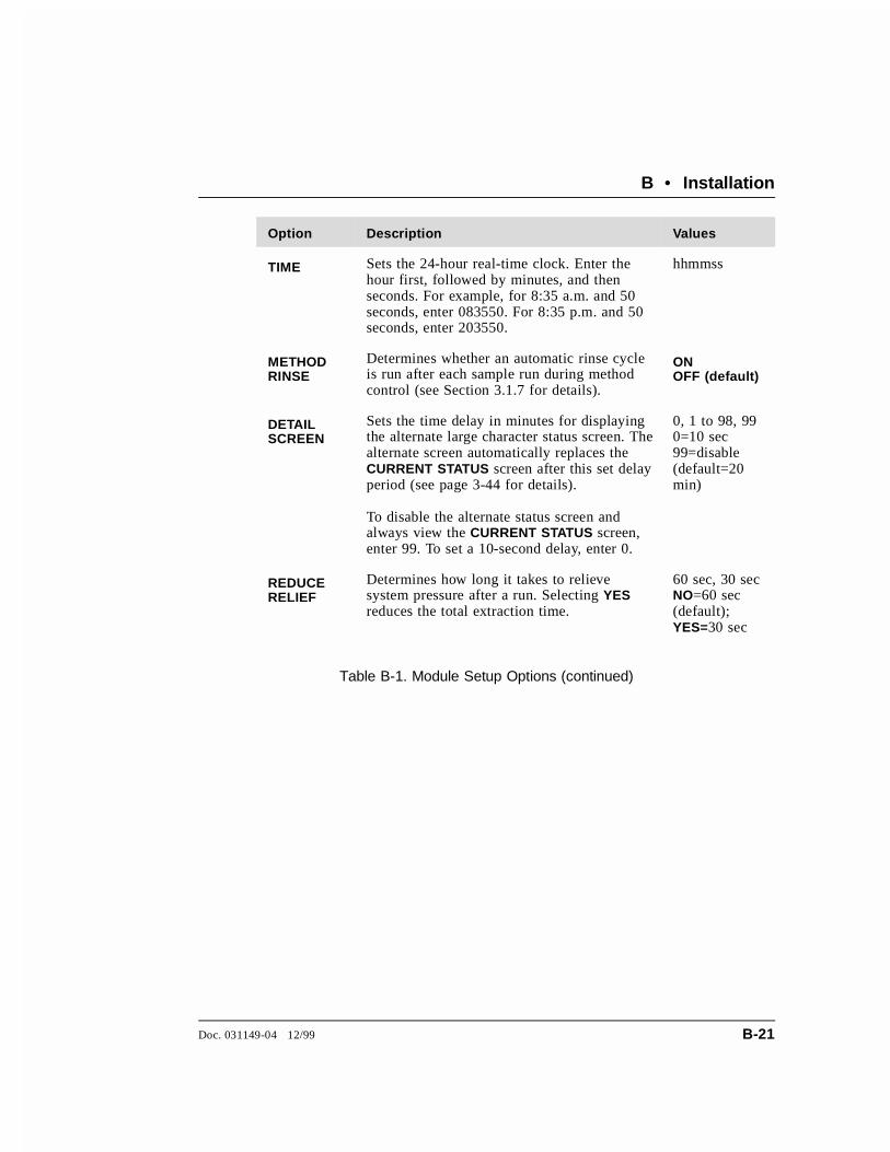
Option Description Values
TIME Sets the 24-hour real-time clock. Enter thehour first, followed by minutes, and thenseconds. For example, for 8:35 a.m. and 50seconds, enter 083550. For 8:35 p.m. and 50seconds, enter 203550.
hhmmss
METHODRINSE
Determines whether an automatic rinse cycleis run after each sample run during methodcontrol (see Section 3.1.7 for details).
ONOFF (default)
DETAILSCREEN
Sets the time delay in minutes for displayingthe alternate large character status screen. Thealternate screen automatically replaces theCURRENT STATUS screen after this set delayperiod (see page 3-44 for details).
To disable the alternate status screen andalways view the CURRENT STATUS screen,enter 99. To set a 10-second delay, enter 0.
0, 1 to 98, 990=10 sec99=disable(default=20min)
REDUCERELIEF
Determines how long it takes to relievesystem pressure after a run. Selecting YESreduces the total extraction time.
60 sec, 30 secNO=60 sec(default);YES=30 sec
Table B-1. Module Setup Options (continued)
B • Installation
Doc. 031149-04 12/99 B-21

B.4 Printer Connections (Optional)
NOTEThe ASE 200 prints through a serial port. If it is necessaryto print from a printer that is not serial-compatible, installa parallel-serial converter. Contact the nearest Dionexoffice for information.
1. Locate the following items in the Ship Kit:
• Printer cable (P/N 960263) with ferrite cylinder (P/N 918019)
• Two ferrite cores (P/N 918013)
• 25-pin/8-pin adapter (P/N 923616)
2. Plug the 25-pin end of the adapter into the 25-pin serialconnector on the printer.
3. Wind the printer cable three turns through the ferrite cylinder, ifthis has not been done already (see Figure B-14). Position thecylinder about 7.5 cm (3 in) from the end of the cable.
Figure B-14. Printer Cable Installation
ASE 200 Operator’s Manual
B-22 Doc. 031149-04 12/99

4. Open the ASE 200 upper front door and plug the end of thecable that is closer to the ferrite cylinder into the top connectoron the Analog card (see Figure B-15).
5. Route the cable through the service chase to the rear of theASE 200 (see Figures B-15 and B-16).
6. Snap the two ferrite cores around the cable where it exits theservice chase (see Figures B-14 and B-16).
7. Plug the printer cable into the 8-pin connector on the adapterthat was plugged into the printer in Step 2.
Figure B-15. Printer Cable Connection (Behind Upper Front Door) (Other Cables Not Shown)
B • Installation
Doc. 031149-04 12/99 B-23

DX LAN
Figure B-16. Rear Panel Service Chase
ASE 200 Operator’s Manual
B-24 Doc. 031149-04 12/99

C • Diagnostic Screens
This appendix describes the ASE 200 diagnostic screens. To openthe DIAGNOSTIC MENU, select screen 7 from the MENU OF SCREENS.
C.1 Power-Up Screen
The POWER-UP screen displays the revision numbers of the ASE 200internal control programs and the identification number of theDX-LAN interface (if connected). The screen is displayed brieflyeach time the ASE 200 is turned on. It is included on the DIAGNOSTIC
TEST MENU to allow access to the information at any time.
32:(5�83 6&5((1
5(*8/$7256(5525 /2*
+<'52&$5%21 &$/,%5$7,21
�
��
�
Figure C-1. Diagnostic Menu
3URPSW
$6( ��� $&&(/(5$7(' 62/9(17 (;75$&725
&23<5,*+7 � ',21(; &253� ���������
02'8/(:$5(
';�/$15(9,'�
Q�QQQ�QQ
'�����%,26
5(9
Figure C-2. Power-Up Screen
Doc. 031149-04 12/99 C-1

C.2 Regulators Screen
• SYSTEM AIR PRESSURE reports the pressure from the compressedair source. This reading should be approximately equal to thereading on the pressure gauge labeled AIR behind the lower door(see Figure B-4 on page B-9).
• OVEN COMPRESSION PRESSURE reports the nitrogen gas pressureapplied to the oven compression system. When the oven is notcompressed, this reading is zero. During an extraction, the ovenis compressed and the reading is approximately 130 psi.
• OVEN COMPRESSION turns pressure to the oven compressionsystem on and off.
Figure C-4 illustrates the gas and air lines and the location of theregulators.
Figure C-3. Regulators Screen
ASE 200 Operator’s Manual
C-2 Doc. 031149-04 12/99

La boratory Com press ed Air0.41 to 1 .38 M Pa
(60 to 200 psi)
N0.97 to 1 .38 M Pa(140 to 200 psi)
2
Figure C-4. Air and Gas Schematic
C • Diagnostic Screens
Doc. 031149-04 12/99 C-3

C.3 Error Log Screen
Records errors that occur during operation and identifies the cell andvial number in use at the time of the error.
When an error occurs during an extraction, the ASE 200 displays anerror message on-screen and records the error on the ERROR LOG
screen. Unless the error causes a shutdown, the ASE 200 continueson to the next cell and vial. If other errors occur during the series ofruns, they are also logged. A maximum of 26 errors can be logged.
To view the list of errors after the run finishes, display the ERROR
LOG screen (press Menu, and then 7). If there are too many errors tobe shown on one screen, use the arrow up and down buttons toscroll through the list. Errors remain on the ERROR LOG screen untilanother method or schedule is loaded.
See Section 4.1 for explanations of the error messages, as well astroubleshooting information.
Figure C-5. Error Log Screen
ASE 200 Operator’s Manual
C-4 Doc. 031149-04 12/99

C.4 Hydrocarbon Calibration Screen
• ACTUAL SENSOR READING reports the hydrocarbon level detectedby the hydrocarbon sensor. This reading should remain at 2000to 4000.
• The UPPER VAPOR THRESHOLD reports the solvent vapor threshold.The threshold should remain at 12000 to 15000.
• CALIBRATE begins the calibration procedure for the hydrocarbonsensor.
For instructions on how to recalibrate the hydrocarbon sensor, referto Section 5.9.
+<'52&$5%21 &$/,%5$7,21
$&78$/ 6(1625 5($',1*�833(5 9$325 7+5(6+2/'�
&$/,%5$7(�
���������<(6
3URPSW
Figure C-6. Hydrocarbon Calibration Screen
C • Diagnostic Screens
Doc. 031149-04 12/99 C-5

ASE 200 Operator’s Manual
C-6 Doc. 031149-04 12/99

D • Reordering Information
P/N Item Quantity
048783 40 mL Clear Collection Vials Pkg. 72048784 60 mL Clear Collection Vials Pkg. 72048780 40 mL Amber Collection Vials Pkg. 72048781 60 mL Amber Collection Vials Pkg. 72
049463 Lids for Collection Vials Pkg. 72049464 Septa for Collection Vials Pkg. 72055395 Teflon/Silicone Low-Bleed Septa for Collection
VialsPkg. 72
055441 40 mL Graduated Concentration Vial Kit (includesclear glass vials, caps, and spacers)
Pkg. 6
055442 40 mL Graduated Concentration Vials Pkg. 6
055421 1 mL Extraction Cells, Assembled Pkg. 6055422 5 mL Extraction Cells, Assembled Pkg. 6
049560 11 mL Extraction Cells, Assembled Pkg. 6049561 22 mL Extraction Cells, Assembled Pkg. 6049562 33 mL Extraction Cells, Assembled Pkg. 6048765 11 mL Extraction Cell, Assembled 1048764 22 mL Extraction Cell, Assembled 1048763 33 mL Extraction Cell, Assembled 1049450 End Caps for Extraction Cells Pkg. 2054973 1 mL Extraction Cell Body 1054974 5 mL Extraction Cell Body 1048820 11 mL Extraction Cell Body 1048821 22 mL Extraction Cell Body 1048822 33 mL Extraction Cell Body 1
049453 Stainless Steel Frits for Extraction Cell Caps Pkg. 50049454 PEEK Seals for Extraction Cell Caps Pkg. 50049455 PEEK Seals for Extraction Cell Caps Pkg. 10
049456 Snap Rings for Extraction Cell Caps Pkg. 10
Doc. 031149-04 12/99 D-1

P/N Item Quantity
049457 External O-Rings for Extraction Cell Caps, Teflon Pkg. 50056325 External O-Rings for Extraction Cell Caps, Viton Pkg. 50
055398 Cellulose Filters for 1 mL Extraction Cell Bodies Pkg. 100055399 Cellulose Filters for 5 mL Extraction Cell Bodies Pkg. 100
049458 Cellulose Filters for 11 mL, 22 mL, or 33 mLExtraction Cell Bodies
Pkg. 100
047017 Glass-Fiber Filters for 11 mL, 22 mL, or 33 mLExtraction Cell Bodies
Pkg. 100
055708 11 mL Cellulose Thimbles Pkg. 25055999 22 mL Cellulose Thimbles Pkg. 25
049288 Aluminum Funnel 1
045900 1 L Glass Bottle, Plastic-Coated 1045901 2 L Glass Bottle, Plastic-Coated 1048670 Bottle Cap Only, Blue 1
049296 Tubing, 4-mm (0.16-in) OD Nitrogen Line Per Ft.053514 Tubing, 8-mm (0.31-in) 0D Vent Line Per Ft.214739 Tubing, 6-mm (0.25-in) OD Air Line Per Ft.049311 Tubing Assembly, Solvent Carrier Line 1215428 Filter for Air Inlet Line 1
049219 Source Needle 1049255 Vent Needle 1
048771 Collection Vial Tray 1049348 Tray Insert for 40 mL Vial 1055444 Vial Spacer for 40 mL Graduated Concentration
Vial1
ASE 200 Operator’s Manual
D-2 Doc. 031149-04 12/99
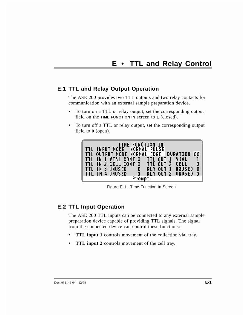
E • TTL and Relay Control
E.1 TTL and Relay Output Operation
The ASE 200 provides two TTL outputs and two relay contacts forcommunication with an external sample preparation device.
• To turn on a TTL or relay output, set the corresponding outputfield on the TIME FUNCTION IN screen to 1 (closed).
• To turn off a TTL or relay output, set the corresponding outputfield to 0 (open).
E.2 TTL Input Operation
The ASE 200 TTL inputs can be connected to any external samplepreparation device capable of providing TTL signals. The signalfrom the connected device can control these functions:
• TTL input 1 controls movement of the collection vial tray.
• TTL input 2 controls movement of the cell tray.
3URPSW
7,0( )81&7,21 ,1
9,$/ &217 9,$/
&(// &217 &(//
8186(' 8186('8186(' 8186('
��
� �
� �
� �
� �
'85$7,2177/ ,1387 02'(
77/ ,1 � 77/ 287 �77/ ,1 � 77/ 287 �77/ ,1 � 5/< 287 �77/ ,1 � 5/< 287 �
77/ 287387 02'(
1250$/ 38/6(
1250$/ ('*(
Figure E-1. Time Function In Screen
Doc. 031149-04 12/99 E-1
E.2.1 TTL Input Signal Modes
The ASE 200 TTL inputs respond to four types of signals toaccommodate different types of device output signals. Thedefault signal mode is normal edge. If the device connectedto the ASE 200 outputs a different signal type, select adifferent signal mode from the TIME FUNCTION IN screen (seeFigure E-1).
These are the four input signal modes:
• Normal Edge: In normal edge operation, the negative(falling) edge of a signal turns on the function and thepositive (rising) edge turns off the function (seeFigure E-2).
• Inverted Edge: The inverted edge mode works identicallyto the normal edge mode, except that the positive andnegative edges are reversed in function.
• Normal Pulse: In normal pulse operation, the negative(falling) edge of the TTL signal is the active edge and thepositive (rising) edge is ignored.
The minimum pulse width guaranteed to be detected is50 ms. The maximum pulse width guaranteed to beignored as noise or invalid is 4 milliseconds. The actionof the ASE 200 is undefined for pulses less than 50 ms orgreater than 4 ms.
• Inverted Pulse: The inverted pulse mode operatesidentically to the normal pulse mode, except that thepositive and negative edges are reversed in function.
ASE 200 Operator’s Manual
E-2 Doc. 031149-04 12/99

Figure E-2. TTL and Relay Input Signal Modes
E • TTL and Relay Control
Doc. 031149-04 12/99 E-3

ASE 200 Operator’s Manual
E-4 Doc. 031149-04 12/99
Index
AAbort button, 2-5Aborting a method or schedule, 2-5, 3-46Acetone, 3-28Acetonitrile, 3-28Acids, 3-2Actuator, power switch, 2-2Air
Checking the pressure, 4-14, C-2Source requirements, B-1Specifications, A-1Substituting nitrogen for, B-20Troubleshooting leaks, 4-24
Air and gas lines schematic, C-3Air inlet filter, B-2Alt button, 2-6Alternate status screen, 2-13, 3-44
Setting the time delay, B-21Analytes, 2-18Analyzing extracts, 3-47Arrow buttons, 2-6ASE 200 Solvent Controller, 1-2, 3-28, B-11AutoASE software, 1-2, 3-42, 3-51Automatic rinse, 3-15, B-21AutoSeal arms, 2-2, 2-11, 2-14
Troubleshooting, 4-9
BBacklight
Adjusting the screen, B-20Bottle, 2-9Bottle gas gauge, B-9Bracket, waste vial
Changing the position, B-13Bubbles in lines, 3-14Buttons
Abort, 2-5Alt, 2-6Cursor arrows, 2-6Delete, 2-6
Enter, 2-6Help, 2-6Menu, 2-6Numeric, 2-6Rinse, 2-5Select, 2-6, 3-27, 4-2, 4-16, 4-17, 4-18Start, 2-5Trays, 2-5
CCable, DX-LAN
Extension cable, B-8Installation, B-7
Canceling a run, 3-46Caps
see also Cell capsVial, 2-8
Cell capsAssembly/disassembly, 5-2Cleaning, 3-47Replacing the frit and seal, 5-2
Cell pressureTroubleshooting, 4-11
Cell tray, 2-2, 2-7Loading, 3-10Troubleshooting, 4-8
Cells, 2-2, 2-7, 2-11Cleaning, 3-47Filling with sample, 3-6Labeling, 3-9Numbering in a schedule, 3-34Sizes of, 2-7, 2-13, 3-6Specifications, A-2Specifying in schedules, 3-35
ChangingFuses, 5-15
Changing solvents, 3-14Check valves, 5-4Chloroform, 3-28Cleaning
Cell cap frit, 5-3
Doc. 031149-04 12/99 Index-1
Cells, 3-47Pump check valves, 5-4Static valve, 5-11
Collection vials, 2-2, 2-8, 2-11see also Vials
Communication screen, 3-48Compressed air requirements, B-1Compression pressure, C-2Concentration of solvent, 3-28Contrast, adjusting the screen, 2-4Control modes, 2-13, 2-22, 3-10, 3-24Control panel, 2-2, 2-3
Keypad, 2-5Creating methods, 3-25Creating schedules, 3-34Current Status screen, 2-12
Setting the display time-out, B-21Cursor arrow buttons, 2-6Cycles
Method parameter, 3-26Specifying multiple, 3-33
DDaily maintenance, 3-49Date, B-20Default
Method parameters, 3-25Module setup options, B-19Schedule parameters, 3-34
Degassing solvents, 3-2Delete button, 2-6Deleting a schedule line, 2-6Deleting values from screen fields, 2-6Description
TTL input control, E-1Detail screen, B-21Detector interface card
Installation, B-7Developing methods, 3-40Diagnostic screens, C-1, C-3, C-5Diatomaceous earth, 3-5Display, 2-3Drying and dispersing agents, 3-4DX-LAN network
Installation, B-7
EEdge input signal mode, E-2Editing methods, 3-29Electrical specifications, A-1Electronics, 2-2
Troubleshooting, 4-21Enlarged character screen, 2-13, 3-44Enter button, 2-6Equilibrium
Solvent/sample, 3-41Temperature, 2-16
Error Log screen, 4-1, C-4Hydrocarbon sensor, 4-18Error messages, 4-1Error sounds
Turning on and off, B-20Ethanol, 3-28Example methods, 3-30Example schedules, 3-36Extraction cells, 2-2, 2-7, 2-11
see also CellsExtraction process, 2-11
Filling the cell, 2-15Flushing the cell, 2-17Heating and static steps, 2-16Loading the cell, 2-14Purging, 2-18Unloading the cell, 2-19, 2-20
ExtractionsRunning multiple on each cell, 3-39Running under method control, 3-42Running under schedule control, 3-45
ExtractsAnalyzing, 3-40, 3-47
FFacility requirements, B-1Features, 2-1Filling the cell, 2-15Filling the solvent bottle, 3-2Filter
Air inlet, B-2Solvent line, 3-2
ASE 200 Operator’s Manual
Index-2 Doc. 031149-04 12/99

Fittings, 5-3Air and gas, B-2, B-4
Fixed time mode, 3-16Flow, 2-21Flush%
Method parameter, 3-26Flushing
Extraction step, 2-17Increasing volume to improve extraction, 3-41Troubleshooting, 4-4
Frit, cell cap, 2-7Functional description
TTL input, E-1Fuses, 5-15, A-1
GGas, 2-18
see also NitrogenFlow path, 2-11Source requirements, B-1Troubleshooting leaks, 4-24
Gas lines schematic, C-3Gauges, 2-9, B-9Guidelines
For developing methods, 3-40
HHeater voltage range switch, B-6Help button, 2-6Hood, 2-10
IIcons used in manual, 1-4IEC safety requirements, 1-4In-line filter, 3-2Inlet filter, B-2Inserting a schedule line, 2-6Inserts, vial tray, 2-9, B-18Installation
Checking pressure gauges, B-9Facility requirements, B-1
Priming the system, B-18Rear panel connections, B-2Solvent compartment connections, B-11Substituting nitrogen for air, B-20TTL/Relay connections, E-3Waste vial, B-13
Inverted edge, E-2Inverted pulse, E-2Iso-octane, 3-28
KKey sounds
Turning on and off, B-20Keypad, 2-5Keys
see Buttons
LLabeling
Cells, 3-9Vials, 3-11
Laboratory air requirements, B-1LCD, 2-2, 2-3Leaks
Gas/air, 4-24Liquid, 4-22
Load Method or Schedule screen, 3-43, 3-45Loading
Cell tray, 3-10Methods, 3-43Schedules, 3-45Troubleshooting, 4-5Vial tray, 3-13
Local mode, 2-22Logging errors, 4-1
MMaintenance, 3-49TTL mode, 3-20Manual
Conventions, 1-3
Index
Doc. 031149-04 12/99 Index-3

Description, 1-3MeCl2, 3-28Menu
Button, 2-6Menus, 2-4Messages
Error, 4-1Safety, 1-4
Methanol, 3-28Method control, 2-22
Definition of, 3-24Running under, 3-42
Method Editor screen, 3-25Method mode, 3-10Preheat, 3-26Method rinse, B-21Methods
Creating, 3-25Default parameters, 3-25Definition of, 3-24Development guidelines, 3-40Editing, 3-29Examples, 3-30Numbering the default method, 3-42Selecting an unused number, 3-27, 4-2, 4-16, 4-17, 4-18Selecting parameters, 3-26, 3-27Specifying in schedules, 3-35
Module Setup screen, 3-15, B-19Multiple extractions, 3-39
NNa2SO4, 3-5Needle mechanism, 2-2, 2-9, 2-11
Replacing the source needle, 5-14Replacing the vent needle, 5-12Troubleshooting, 4-6
Nitrogen, 2-11, 2-18, A-1Gauge, B-9Source requirements, B-1Substituting for compressed air, B-20
Normal edge, E-2Normal pulse, E-2Numeric buttons, 2-6
OO-rings, 3-9, B-15
Replacement schedule, 3-49, 4-14Replacing, 4-22
Fixed time mode, 3-17, 3-19Operating configuration
TTL input, E-1Operating features, 2-1Operating modes, 2-22Options
ASE 200 accessories, 1-2Setting operating options, B-19
Oven, 2-2, 2-11Automatic shut-off, 3-51Checking the compression pressure, C-2Heat up and cool down, 3-44, 3-46Troubleshooting, 4-4Voltage range switch, B-6
Oven Wait message, 3-44, 3-46
PPart numbers, D-1Parts replacement, D-1PEEK seal, cell cap, 2-7
Replacement procedure, 5-2Replacement schedule, 3-49
Periodic maintenance, 3-49Physical dimensions, A-1Post-extraction procedures, 3-47Power cord, B-5Power requirements, A-1, B-1Power switch, 2-2Power-up, 2-4, B-16Power-Up screen, C-1Preparing sample, 3-3Preparing to run, 3-1Pressure, 2-13
Checking the system air pressure, 4-14, C-2Controlling, 2-21Oven compression, C-2Sealing the cell, 2-14Selecting the unit of measure, B-20Set point during extraction, 2-16, 3-27To the solvent bottle, 2-21
ASE 200 Operator’s Manual
Index-4 Doc. 031149-04 12/99

Pressure gauges, 2-9, B-9Pressure relief valve, 2-9, 2-11, 2-21
Replacing, 5-10Prime valve, 2-11, 2-21Priming the system, 2-5, 3-14, B-18Printing, 3-48
Connecting a printer, B-20Troubleshooting, 4-25
Process, 2-11Processing extracts, 3-47Pulse input signal mode, E-2Pump, 2-11, 2-21
Solenoids, 3-49Specifications, A-2
Pump check valves, 5-4Purge
Method parameter, 3-26Purge valve, 2-11, 2-21Purging, 2-18
RReal-time clock, B-20Rear panel, B-2Refilling the solvent bottle, 3-14Regulators, B-10Regulators screen, C-2Relief valve, 2-9, 2-11, 2-21
Cleaning/replacing, 5-10Remote mode, 2-22Replacing
Cell frit and seal, 5-2Needles, 5-12Pressure relief valve, 5-10Pump check valves, 5-4Static valve, 5-11Tubing and fittings, 5-3
Reports, 3-48Do not print, 4-25
Reservoir, 2-9Connections, B-11Filling, 3-2
Revision numbers, C-1Revisions, Moduleware, BIOS, B-17Rinse button, 2-5
Rinse cycle, 2-5, 2-7, 3-14Automatic, 3-15, B-21Specifying in schedules, 3-35
Rinse tubes, 2-7, 3-10, B-15Rinse vials, 2-8Routine maintenance, 3-49RTD, troubleshooting, 4-12Running, 3-1
Aborting a run, 3-46Under method control, 3-42Under schedule control, 3-45
SSafety icons, 1-4Safety messages, 1-4Sample cells, 2-7, 2-11
see also CellsSamples
Difficulty in extracting, 3-41Identifying in schedules, 3-35Preparing, 3-3
Saving methods, 3-27Saving schedules, 3-35Schedule control, 2-22
Definition of, 3-24Schedule Editor
Default parameters, 3-34Schedules
Creating, 3-34Definition of, 3-24Deleting and inserting lines, 2-6Examples, 3-36Running, 3-45Saving, 3-35Specifying parameters, 3-35Using for method development, 3-40
SchematicAir and gas lines, C-3Solvent flow, 3-49System Overview, 2-11
Screen backlightingAdjusting, B-20
Screen contrastAdjusting, 2-4
Index
Doc. 031149-04 12/99 Index-5

Screens, 2-3Alternate status, 2-13, 3-44Communication, 3-48Current Status, 2-12, B-21Diagnostic Menu, C-1, C-3, C-5Error Log, C-4Load Method or Schedule, 3-43Method Editor, 3-25Module Setup, 3-15, B-19Power-Up, C-1Regulators, C-2Schedule Editor, 3-34
Scrolling the schedule screen, 3-34Seals
Cell cap replacement procedure, 5-2Cell cap replacement schedule, 3-49
Select buttons, 2-6Selecting options, 2-6Sensors
Cell size, 2-7Vial absent, vial full, 2-9, 3-11
Serial number, 3-7, 3-9Service procedures
Changing fuses, 5-15Cleaning/replacing pump check valves, 5-4Replacing needles, 5-12Replacing the cell frit and seal, 5-2Replacing the pressure relief valve, 5-10Replacing the source needle, 5-14Replacing the static valve, 5-11Replacing tubing and fittings, 5-3
Set point temperature, 3-44Ship Kit, B-2Shutdown, 3-51Signal modes for TTL input, E-2Site requirements, B-1Skipping cell numbers, 3-34Solenoids, 2-21, 3-49Solvent
Controlling flow, 2-21Filling the bottle, 3-2Flow schematic, 3-49Preparing, 3-1Rinsing after changing, 3-14Specifying in a method, 3-27, 3-28Usage, 3-6
Solvent bottle, 2-9, 2-11
Connections, B-11Solvent compartment, 2-2, 2-9
Connections, B-11Solvent flow path, 2-11
Troubleshooting, 4-6, 4-23Sonicating, 5-3, 5-5Source needle, 5-14Specifications, A-1, A-3
Air and gas, A-1Cell, vials, trays, A-2Electrical, A-1Environmental, A-1Oven, A-2Physical, A-1Pump, A-2Sensors, A-3Valves, A-3
Stainless steelCell cap frit, 2-7
Start button, 2-5Starting
A method, 3-43A schedule, 3-45
Static method parameter, 3-26Static valve, 2-11, 2-15, 2-16, 2-21
Replacing, 5-11Status screen, 2-12
Setting the display time-out, B-21Step Time, 2-13Steps, 2-11
Filling the cell, 2-15Flushing the cell, 2-17Heating and static, 2-16Loading the cell, 2-14Purging, 2-18Unloading the cell, 2-19, 2-20
Stopping a method or schedule, 2-5, 3-46Symbols, 1-5System air gauge, B-9System air pressure, 4-14, C-2System status, 2-13
ASE 200 Operator’s Manual
Index-6 Doc. 031149-04 12/99
TTemperature, 2-13
Increasing to improve extraction, 3-40Reaching the set point, 2-14, 3-44
Terminator plugs, B-8THF, 3-28Time, B-21Time Function In screen, E-2Toluene, 3-28Transducer, 3-49Tray
Cell, 2-2, 2-7, 3-10Engaging/disengaging, 2-5Vial, 2-2, 2-8, 3-11
Trays button, 2-5Troubleshooting
Cell tray, 4-8Electrical, 4-21Error messages, 4-1Excessive cell pressure, 4-11Flushing, 4-4Gas/air leaks, 4-24Loading, 4-5Needle mechanism, 4-6Oven, 4-4Pressure Relief valve, 4-24Reports do not print, 4-25RTD, 4-12Safety condition, 4-6Solvent flow blocked, 4-6System has stopped, 4-20Vial tray, 4-7
TTL mode, 3-19TTL/Relay control, E-1
Connectors, E-1Input operation, E-1Input signal modes, E-2Installation, E-3Output operation, E-1
Tubing, 5-3Air and gas, B-2Vent, B-4
UUnloading
Cell from the oven, 2-19, 2-20
VValves
Pressure relief, 2-9, 2-11, 2-21, 5-10Prime, 2-11, 2-21Pump check valves, 5-4Purge, 2-11, 2-21Specifications, A-3Static, 2-11, 2-15, 2-16, 2-21, 5-11Troubleshooting, 4-24
Valves’ status, 2-13Vent lines, 2-9, 2-11Vent needle
Replacing, 5-12Venting
Pressure, 2-20Vial caps, 2-8Vial tray, 2-2, 2-8
Inserts for 40 mL vials, 2-9, 3-13, B-18Removing and installing, 3-11Rinse slots, 3-13Troubleshooting, 4-7
Vials, 2-2, 2-8, 2-11Labeling, 3-11Loading on tray, 3-13Sizes of, 3-11Specifications, A-2Where to place a label, 3-12
Voltage range switch, B-6Volume of solvent pumped, 2-13
WWaste vial, 2-9, 2-11
Installation, B-13Water, 3-28
Index
Doc. 031149-04 12/99 Index-7

ASE 200 Operator’s Manual
Index-8 Doc. 031149-04 12/99