asd tug specification_ptb
TRANSCRIPT
1
TECHNICAL SPECIFICATION
Of
50 Ton Bollard Pull
Azimuth Stern Drives – Escort Tug
With
Fire Fighting Capability
(Fifi 1/2)

2
C O N T E N T S Page Section 1 General 29
Section 2 Leading particulars 31
Section 3 Hull 32
Section 4 accommodation 36
Section 5 Towing equipment 37
Section 6 Machinery 38
Section 7 Fire fighting equipment 44
Section 8 Electrical installation 46
Section 9 Paint and Corrosion Protection 49
Section 10 Lifesaving and Safety Equipment 50
Section 11 Spares 51
3
SECTION 1 – GENERAL 1.1 General Requirement The vessel shall be complete in all respects and made ready for sea in
accordance with this outline specification with the usual requirements for a first class ship of this size and type. It is to be understood that anything omitted from this specification, but which is necessary for the working of the vessel, is nevertheless to be supplied without additional charge, insofar as it is usually supplied for this class of vessel.
The following climatic conditions have to be considered: - ambient air temperature : 40 deg C - seawater temperature : 33 deg C - max. relative humidity : 90% 1.2 Scope of Work To construct, launch, equip and deliver twin engine tractor tugs driven
by cycloidal propellers for following special duties: a. Escorting and giving breaking and steering assistance for incoming
ships, b. Shiphandling of all kind of LNG Carrier in harbour and in coastal
area c. Operation as stand-by vessel d. Pushing and pulling duties e. Fire fighting with excellent station keeping capabilities f. Deep Sea operation with working outside of harbour under worst
weather conditions. Builders are demanded to take special care that for meeting these
different tasks vessel's propulsion system must allow simple, i.e. human engineered control.
For the specified tasks the highest degree of safety, shiphandling ability
and manoeuvrability, at all ships speeds is required. Stability to at least comply with the latest requirements but in any
condition the positive metacentric height to be as large to provide an ample stable platform when fire pumps are in operation and monitors are directing water jets to one side. The heeling angle under such condition should be kept to a minimum (static).
Stability has to comply with the escort requirements. 1.3 Country of Makers All main machineries and equipments shall be only manufactured at
Japan and/or European countries and/or United States of America, as per attached maker list.
1.4 Drawings Class approval drawings of the vessel, machinery and equipment to be
submitted to the ship owner for approval before the relevant work is commenced.
4
1.5 Classification The vessel's machinery and equipment to be designed and built under
survey of a Classification society IACS member. 1.6 Registry The vessel shall be registered under Indonesian flag. 1.7 Regulations The vessel shall be in accordance with the latest statutory regulations of
the country of registry and the governing requirements and standards of various other statutory bodies insofar as they relate to accommodation, lights, life saving appliances, electrical installation, noise levels etc.
1.8 Sea Trial Sea trial is to be arranged and carried out in accordance with a program
appoved by the Classification Society. Provider is to supply a master, crew and necessary equipment and arranged the catering. All diesel fuel, lubrication, frest water, pilotage, standby vessel and dues for the trials are to be paid for by the provider. The compass is to be adjusted during sea trial.
The following tests are to be carried out during sea trial: - Speed Trials; - Endurance trials; - Steering Trials; - Stopping & Astern Trials; - Vibration and Noise measurement; - Anchor & Mooring equipment; - Bollard Pull Trials.
5
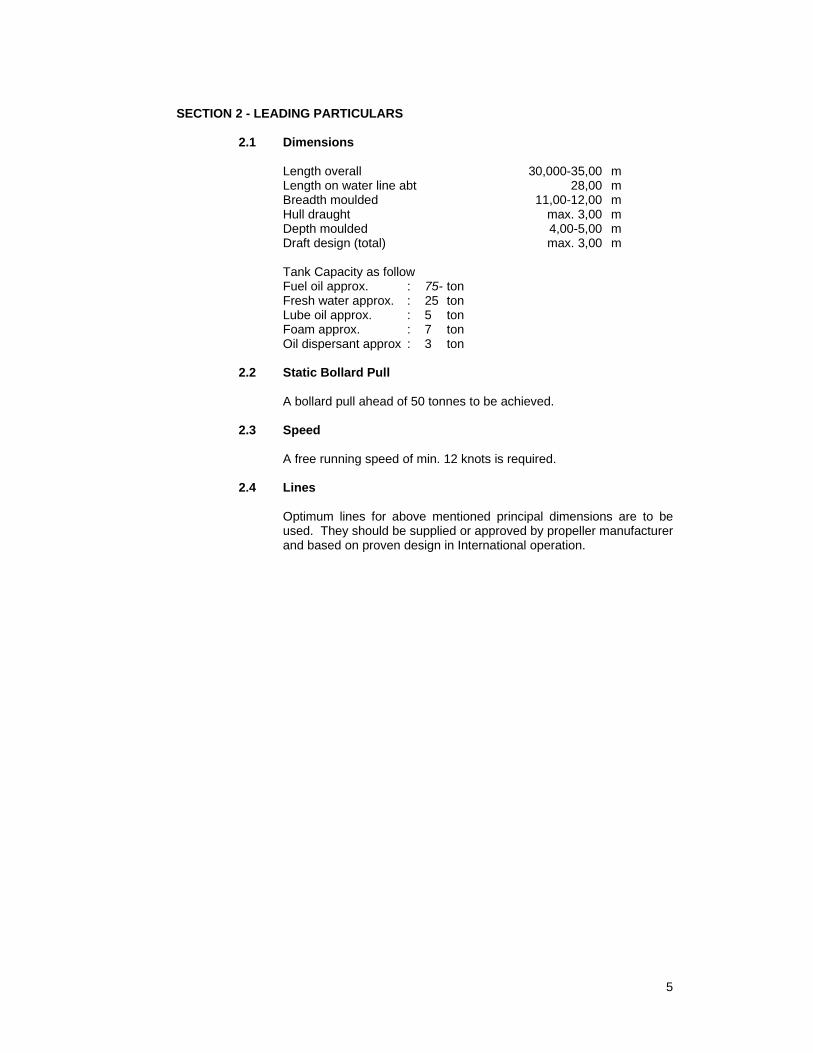
SECTION 2 - LEADING PARTICULARS 2.1 Dimensions Length overall 30,000-35,00 m Length on water line abt 28,00 m Breadth moulded 11,00-12,00 m Hull draught max. 3,00 m Depth moulded 4,00-5,00 m Draft design (total) max. 3,00 m Tank Capacity as follow Fuel oil approx. : 75- ton Fresh water approx. : 25 ton Lube oil approx. : 5 ton Foam approx. : 7 ton Oil dispersant approx : 3 ton 2.2 Static Bollard Pull A bollard pull ahead of 50 tonnes to be achieved. 2.3 Speed A free running speed of min. 12 knots is required. 2.4 Lines Optimum lines for above mentioned principal dimensions are to be
used. They should be supplied or approved by propeller manufacturer and based on proven design in International operation.
6
SECTION 3-HULL 3.1 Steelwork Generally All steelwork shall be Grade A approved by class. All-welded
construction with scantlings shall be in accordance with rules + 10 % for the full draught allowable on the dimensions. All steel shall be dry grit blasted to remove all mill scale before being worked, followed immediately by shop primer compatible with painting scheme.
3.2 Keel No flat plate type is required. 3.3 Stem Steel plate with sufficient stiffeners. 3.4 Stern Steel plate and structure reinforced for main pushing direction astern.
Freeboard aft to be as large as possible. 3.5 Skeg Double plate profile shape construction with flat bottom and floor
plates at every frame. Thoroughly connected to main hull construction and of ample strength to support its share of the vessel's weight when the vessel is dry-docked. Filling and drain plugs for filling with approved bituminous solution and subsequent draining for proper conservation.
3.6 Frames Frame spacing abt 500 mm. At least three web frames in range of
main engines and three in way of propeller wells. 3.7 Centre Girder Continuous between peak bulkheads, of increased height between
engines and propellers as far as practical. 3.8 Stringers Carried as far forward and aft as possible. Face flats continuous
between bulkheads. Side stringer of same width as web frames about midway between deck and tops of floors.
3.9 Machinery Seating Main engine seating carried through from after engine room bulkhead
to forward of the propeller wells. 3.10 Propeller Wells Propeller wells with proper stiffening in all directions in order to
transmit forces (propeller thrust and grounding forces), properly integrated into hull bottom structure. Final design to be approved by propeller manufacturer.
7
3.11 Echo Sounder To be installed in fore part of propeller guard on centre in watertight
compartment. Wiring through forward centre strut through small separate pipe of adequate diameter. Printer to be considered.
3.12 Shell and Deck Plating Steel with flush welded butts and seams. Insert plates of increased
thickness in way of openings, protection plate struts, under deck machinery, fairleads, bollards and elsewhere as required. Doubling plates will not be accepted. Main deck aft to be strengthened for pushing duties.
3.13 Main Deck Bulwarks Height abt 1000 mm above top of steel deck to top of rail, set inboard
by abt. 150 - 200 mm and tumblehome large enough to avoid contacts with other ship hulls when working alongside or pushing, considering heeling of the tractor under ships with large flare. Aft tumblehome arranged to give view to aft fender from control stand in wheelhouse. Stanchions at least at every third main deck beam and bulwark specially strengthened at bow and stern to approval.
Open bulwark just above main deck complete fore and aft as
practicable, under fairleads closed. Thimbles of at least 100 mm in diameter clear opening for portable
fenders each, side. 3.14 Fendering For bow block fender of adequate height. Tyres to be arranged also
alongside for berthing on a strong sheer strake of 600 mm height. Stern fender: Of tubular design according to general arrangement arranged on top
of block fenders. Full foundation for-round fender, duplex, webbing for securing, inside through fender with galvanised chain. Ends of round fender is inside bulwark.
3.15 Deckhouse Of steel plates with stiffeners at every deck beam as far as possible. 3.16 Wheelhouse As compact as possible to allow just the installation of the necessary
controls but to allow for optimised visibility in all directions and working areas. A mock-up has to be built to prove this. Floor to be raised to allow void space for control installation. Sides and ends inclined at an angle of about 15 degrees, but no part of house to lie outside a line drawn at minimum 20 degrees from the outside edge of the side fender.
Full height windows in after end and low level windows at side. Fixed
window in wheelhouse sides forward port and starboard between
8
normal windows and deck for view of vessel's shoulder when berthing. It is to be understood that the windows of the wheelhouse have to be as large as possible with respect to maximum visibility around when standing at the propeller control stand. Side windows to be opened top and bottom.
Windows on top where necessary to allow eye contact to top of ships
to be handled. Good all round visibility is essential and all fittings on bridge deck to be arranged to give maximum view in all directions.
3.17 Wheelhouse Equipment Wheelhouse equipment to include: - Necessary equipment for unmanned engine room, start
from the bridge/engine room. - Two control stands for remote control of propellers, arranged for
optimised view in all working directions in wheelhouse. Control stands with two pitch levers for the longitudinal and one wheel for the transverse pitch control. The control lines between stand and propellers to be of mechanical type.
- Deckhead compass reflector (compass fitted on flying bridge). - Navigation light panel with switches and alarms. - Marine type telephone with selector panel. - Clock, 200 mm 8 day. Hinged chart table. - Upholstered swivelling chair aft of control stand. - Echo sounder video - Two V.H.F. radio set and a radar set will be installed. The
necessary wiring is to be installed to suit an extension loud speaker and hand sets in the mess room and in the master's cabin.
- Racks for binoculars, navigation instruments, drinking mugs. - Storm rails all round inside. - Winch control - Fire fighting control - Engine control - Radar - Auto-pilot 3.18 Fly Bridge Top of wheelhouse to form flying bridge, with access ladder to be
arranged as convenient. Open rails 1,0.00 mm high all round. Equipment to include reflector compass on centre line fand searchlight. Searchlight to be arranged to reach forward and aft working area.
3.19 Fire Monitors One fire fighting monitor aft of the wheelhouse to be arranged. Monitor
to be controlled from inside of wheelhouse. 3.20 Ventilation and Air Condition Air-condition shall be provided in crews' spaces, stores and other
spaces and shall be in accordance with the latest requirements to the Statutory Bodies.
9
Combustion and ventilation air in engine room to be supplied by two variable speed fans.
3.21 Mast A steel mast to be connected to flying bridge. To be of sufficient
strength and stiffness to avoid vibration. Mast to carry brackets fitted for the dual Voltage electric navigation lights and for radar scanner.
Dual navigation lights to be arranged for both directions of operation. 3.22 Coating All paints to be supplied by an approved manufacturer and all painting
to be carried out in accordance with the manufacturer's agreed specification and recommendations.
3.23 Cathodic Protection System of cathodic protection using zinc anodes to be of the bolted
type. 3.24 Windlass One (1) electro hydraulic windlass of ample power to handle two
anchor, cable lifter and one warping end. Full load of 2 t at speed drum about 10 m per minute and light load speed at least 20 m per minute.
3.25 Hawse Pipe Fabricated steel on port side and starboard side to give easy lead to
cable lifters and windlass. Anchor recessed within shell and well clear of bow fendering.
3.26 Bollards, Mooring Pipes, etc. At least four fabricated steel bollards and four cast steel, mooring
pipes in bulwarks to give good lead on to bollards. Cleats and other fittings required for efficient operation of vessels. On centre in bulwark aft a Panama chock to be arranged. Bulwark and deck to be strengthened correspondingly.
3.27 Life Saving Equipment Full complement of life saving equipment to the relevant Statutory
Bodies requirement.
10
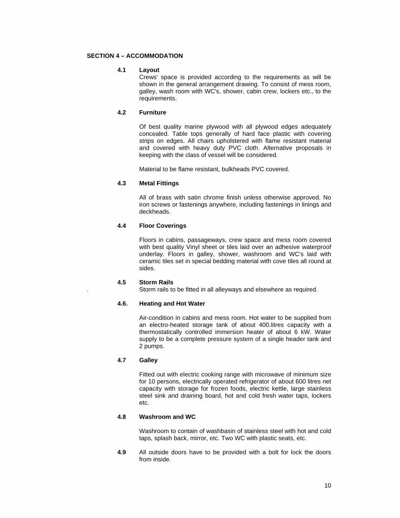
SECTION 4 – ACCOMMODATION 4.1 Layout Crews' space is provided according to the requirements as will be
shown in the general arrangement drawing. To consist of mess room, galley, wash room with WC's, shower, cabin crew, lockers etc., to the requirements.
4.2 Furniture Of best quality marine plywood with all plywood edges adequately
concealed. Table tops generally of hard face plastic with covering strips on edges. All chairs upholstered with flame resistant material and covered with heavy duty PVC cloth. Alternative proposals in keeping with the class of vessel will be considered.
Material to be flame resistant, bulkheads PVC covered. 4.3 Metal Fittings All of brass with satin chrome finish unless otherwise approved. No
iron screws or fastenings anywhere, including fastenings in linings and deckheads.
4.4 Floor Coverings Floors in cabins, passageways, crew space and mess room covered
with best quality Vinyl sheet or tiles laid over an adhesive waterproof underlay. Floors in galley, shower, washroom and WC's laid with ceramic tiles set in special bedding material with cove tiles all round at sides.
4.5 Storm Rails . Storm rails to be fitted in all alleyways and elsewhere as required. 4.6. Heating and Hot Water Air-condition in cabins and mess room. Hot water to be supplied from
an electro-heated storage tank of about 400.litres capacity with a thermostatically controlled immersion heater of about 6 kW. Water supply to be a complete pressure system of a single header tank and 2 pumps.
4.7 Galley Fitted out with electric cooking range with microwave of minimum size
for 10 persons, electrically operated refrigerator of about 600 litres net capacity with storage for frozen foods, electric kettle, large stainless steel sink and draining board, hot and cold fresh water taps, lockers etc.
4.8 Washroom and WC Washroom to contain of washbasin of stainless steel with hot and cold
taps, splash back, mirror, etc. Two WC with plastic seats, etc. 4.9 All outside doors have to be provided with a bolt for lock the doors
from inside.
11
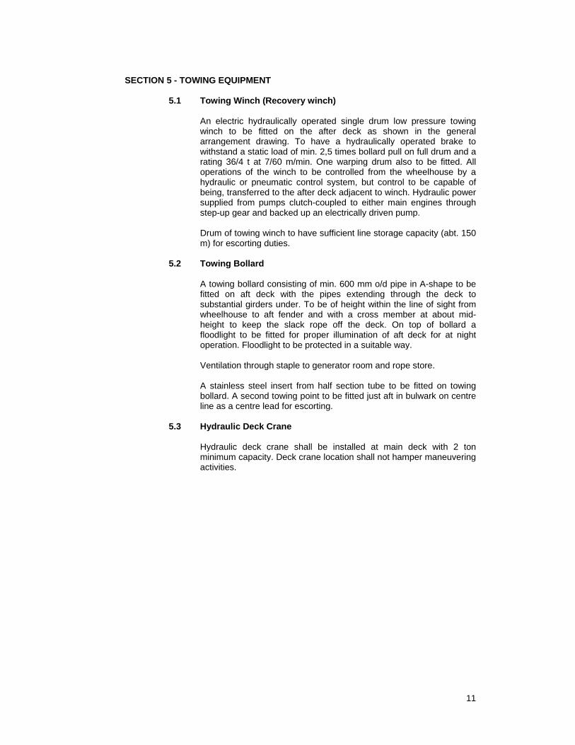
SECTION 5 - TOWING EQUIPMENT 5.1 Towing Winch (Recovery winch) An electric hydraulically operated single drum low pressure towing
winch to be fitted on the after deck as shown in the general arrangement drawing. To have a hydraulically operated brake to withstand a static load of min. 2,5 times bollard pull on full drum and a rating 36/4 t at 7/60 m/min. One warping drum also to be fitted. All operations of the winch to be controlled from the wheelhouse by a hydraulic or pneumatic control system, but control to be capable of being, transferred to the after deck adjacent to winch. Hydraulic power supplied from pumps clutch-coupled to either main engines through step-up gear and backed up an electrically driven pump.
Drum of towing winch to have sufficient line storage capacity (abt. 150
m) for escorting duties. 5.2 Towing Bollard A towing bollard consisting of min. 600 mm o/d pipe in A-shape to be
fitted on aft deck with the pipes extending through the deck to substantial girders under. To be of height within the line of sight from wheelhouse to aft fender and with a cross member at about mid-height to keep the slack rope off the deck. On top of bollard a floodlight to be fitted for proper illumination of aft deck for at night operation. Floodlight to be protected in a suitable way.
Ventilation through staple to generator room and rope store. A stainless steel insert from half section tube to be fitted on towing
bollard. A second towing point to be fitted just aft in bulwark on centre line as a centre lead for escorting.
5.3 Hydraulic Deck Crane Hydraulic deck crane shall be installed at main deck with 2 ton
minimum capacity. Deck crane location shall not hamper maneuvering activities.
12
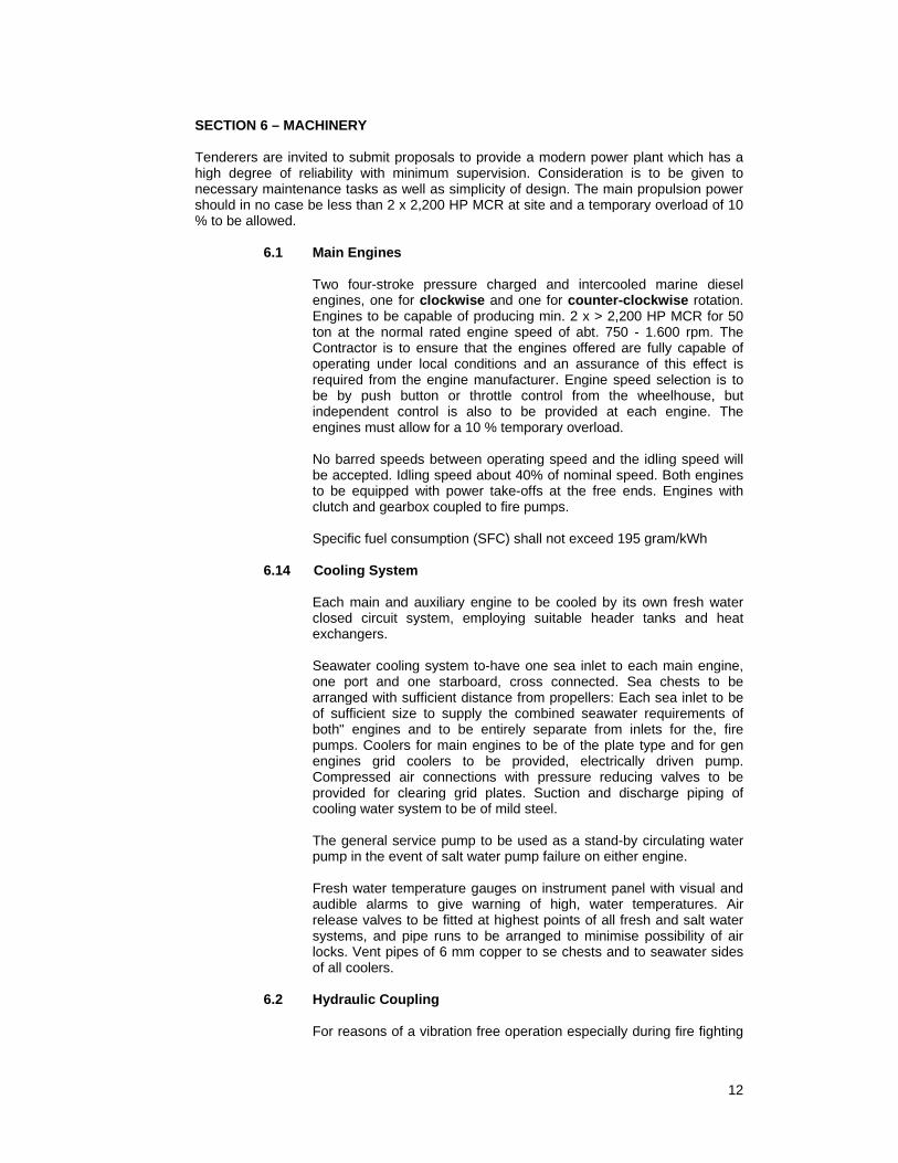
SECTION 6 – MACHINERY Tenderers are invited to submit proposals to provide a modern power plant which has a high degree of reliability with minimum supervision. Consideration is to be given to necessary maintenance tasks as well as simplicity of design. The main propulsion power should in no case be less than 2 x 2,200 HP MCR at site and a temporary overload of 10 % to be allowed. 6.1 Main Engines Two four-stroke pressure charged and intercooled marine diesel
engines, one for clockwise and one for counter-clockwise rotation. Engines to be capable of producing min. 2 x > 2,200 HP MCR for 50 ton at the normal rated engine speed of abt. 750 - 1.600 rpm. The Contractor is to ensure that the engines offered are fully capable of operating under local conditions and an assurance of this effect is required from the engine manufacturer. Engine speed selection is to be by push button or throttle control from the wheelhouse, but independent control is also to be provided at each engine. The engines must allow for a 10 % temporary overload.
No barred speeds between operating speed and the idling speed will
be accepted. Idling speed about 40% of nominal speed. Both engines to be equipped with power take-offs at the free ends. Engines with clutch and gearbox coupled to fire pumps.
Specific fuel consumption (SFC) shall not exceed 195 gram/kWh 6.14 Cooling System Each main and auxiliary engine to be cooled by its own fresh water
closed circuit system, employing suitable header tanks and heat exchangers.
Seawater cooling system to-have one sea inlet to each main engine,
one port and one starboard, cross connected. Sea chests to be arranged with sufficient distance from propellers: Each sea inlet to be of sufficient size to supply the combined seawater requirements of both" engines and to be entirely separate from inlets for the, fire pumps. Coolers for main engines to be of the plate type and for gen engines grid coolers to be provided, electrically driven pump. Compressed air connections with pressure reducing valves to be provided for clearing grid plates. Suction and discharge piping of cooling water system to be of mild steel.
The general service pump to be used as a stand-by circulating water
pump in the event of salt water pump failure on either engine. Fresh water temperature gauges on instrument panel with visual and
audible alarms to give warning of high, water temperatures. Air release valves to be fitted at highest points of all fresh and salt water systems, and pipe runs to be arranged to minimise possibility of air locks. Vent pipes of 6 mm copper to se chests and to seawater sides of all coolers.
6.2 Hydraulic Coupling For reasons of a vibration free operation especially during fire fighting
13
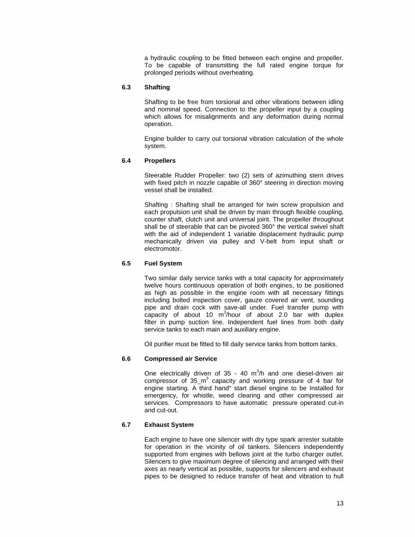
a hydraulic coupling to be fitted between each engine and propeller. To be capable of transmitting the full rated engine torque for prolonged periods without overheating.
6.3 Shafting Shafting to be free from torsional and other vibrations between idling
and nominal speed. Connection to the propeller input by a coupling which allows for misalignments and any deformation during normal operation.
Engine builder to carry out torsional vibration calculation of the whole
system. 6.4 Propellers Steerable Rudder Propeller: two (2) sets of azimuthing stern drives
with fixed pitch in nozzle capable of 360° steering in direction moving vessel shall be installed.
Shafting : Shafting shall be arranged for twin screw propulsion and
each propulsion unit shall be driven by main through flexible coupling, counter shaft, clutch unit and universal joint. The propeller throughout shall be of steerable that can be pivoted 360° the vertical swivel shaft with the aid of independent 1 variable displacement hydraulic pump mechanically driven via pulley and V-belt from input shaft or electromotor.
6.5 Fuel System Two similar daily service tanks with a total capacity for approximately
twelve hours continuous operation of both engines, to be positioned as high as possible in the engine room with all necessary fittings including bolted inspection cover, gauze covered air vent, sounding pipe and drain cock with save-all under. Fuel transfer pump with capacity of about 10 m3/hour of about 2.0 bar with duplex filter in pump suction line. Independent fuel lines from both daily service tanks to each main and auxiliary engine.
Oil purifier must be fitted to fill daily service tanks from bottom tanks. 6.6 Compressed air Service One electrically driven of 35 - 40 m3/h and one diesel-driven air
compressor of 35_m3 capacity and working pressure of 4 bar for engine starting. A third hand" start diesel engine to be Installed for emergency, for whistle, weed clearing and other compressed air services. Compressors to have automatic pressure operated cut-in and cut-out.
6.7 Exhaust System Each engine to have one silencer with dry type spark arrester suitable
for operation in the vicinity of oil tankers. Silencers independently supported from engines with bellows joint at the turbo charger outlet. Silencers to give maximum degree of silencing and arranged with their axes as nearly vertical as possible, supports for silencers and exhaust pipes to be designed to reduce transfer of heat and vibration to hull
14
and funnel structure. Exhaust pipes and silencers to be thoroughly lagged in accordance with latest requirement to reduce heat and noise to the maximum extent. Silencers to be arranged in superstructure in order to keep funnels small.
6.8 Funnel Two funnels of low height to house all exhaust pipes, of minimum
dimensions to cause minimum of obstruction to visibility from wheelhouse. Height of exhaust pipes to be at least to wheelhouse deck level. Thoroughly stiffened at base. Outside of funnels to be inclined inboards.
6.9 Auxiliary Pumps Generally The following are required, all electrically driven: - 2 general service pumps, each abt. 45 m3/h at 5 bar - Fuel transfer pump, abt. 10 m3/h at abt. 2.0 bar - 1 Fuel oil purifier - Domestic fresh water pumps (2 pumps on 1 bladder) - Standby lubricating oil pumps - Dirty oil pump 6.10 General Service Pump Exactly as bilge pump, but additional services to include foam system
flushing and standby fresh and salt water services to main engines, and water spray curtain. To be connected to the freshwater system by a spectacle piece.
6.11 Fuel Transfer Pump Gear type having capacity of about 10 m3 per hour. To draw from
either main fuel tank and deliver to the other tank and overboard through the filling connections. A hand pump to perform similar duties is required.
6.12 Domestic Service Pump One domestic fresh water pressure system with pump and pressure
vessel mounted as a complete unit. Pump to have gunmetal casing. Pressure switch set to cut-in at about 1.0 bar and cut-out at about 2.0 bar. To serve both sanitary and water systems, including cold water supply to hot water tank.
An evaporator of 2 ton capacity per day to be installed. 6.13 Standby Lubrication Oil Pump Connected with suitable pipes and valves to main engine lubricating
oil systems. Of sufficient capacity to enable either main engine to be run continuously at maximum power.
6.13.1 Lubricating Oil In double bottom in engine room a lubricating oil tank of about 10 m3
to be arranged.
15
6.14 Dirty Oil Pump To draw from sludge tank in bilge and discharge to hose connection
on deck. 6.15 Oily Water Separator Electrically operated and in accordance with Oil in Navigable Water
Act, Ship's Equipment Regulations. Self-contained unit with suctions to engine room bilge separate from the ship's bilge pumping system. To discharge sludge to a special tank in the engine room bilge and clean water overboard. Capacity to be of about 0.5 m^/hour.
6.16 Sewage Plant A small sewage treatment plant of sufficient capacity for a crew of
sixteen (16) men and treat all sewage material, rendering it safe for discharge into the enclosed docks. Overboard facilities to be fitted.
6.17 Pumping and Piping All piping to be manufactured from seamless steel tube except for low
pressure applications. Small bore pipes may be manufactured from solid drawn copper if desired. Pipes which are to be galvanised to be thoroughly cleaned and then immediately galvanised after all working has been completed.
Bilge system pipes of adequate diameter galvanised steel. Mud boxes
to be fitted wherever possible in preference to strums. Ballast system pipes of adequate diameter galvanised steel with
suction and discharge pipes to aft ballast tanks. All piping passing through bulkheads or deck to have special bulkhead
fittings with enlarged flange bolted to bulkhead and standard flanges for pipe connections. All pipes to be in readily removable flanged lengths, securely clipped in hangers, those for copper pipes being lined with lead or other approved material. Earthing strips of copper to be fitted as necessary. No pipes carrying flammable liquids to be run over engines or other hot surfaces.
All ship's side valves of gunmetal. Except where screw down or screw
down non-return valves are required for classification requirements, replaceable butterfly valves are to be used where conditions allow. Changeover valves to be fitted generally throughout all systems in preference to switch cocks.
All valves and pipes to be clearly marked in code colours for
identification. Markings to be in English. Domestic hot and cold fresh water pipes of copper, except that cold
water piping outside of engine room may be-of high impact PrV.C-. which must be supported in special clips to approval.
Sacrificial anodes have to be provided inside the saltwater pipes.
16
6.18 Propeller Control Propellers to be controlled from the wheelhouse by means of one,
alternatively two control station(s). 6.19 Platforms and Gratings Where platforms and gratings are necessary in maintenance areas
around the machinery or the propellers it has to be made removable for easy access and to be of aluminium.
6.20 Overhauling Tackle Beams and lifting gear complete arranged over main engines,
shaftings and propellers, of adequate type and number for the removal of parts and to facilitate maintenance. An ample number of large diameter eye plates to be welded to deck and beams above propellers for the removal and stowage of major part in the event of a general overhaul. Similar beams and eye plates to be fitted where necessary over auxiliaries, shafting, turbo couplings and other heavy equipment.
6.21 Remote Control Engine room control panel of adequate size to be arranged aft in
engine room. Instruments neatly arranged and grouped for ease of reading and to
include for each main and auxiliary engine: - Engine speed tachometer - Lubricating oil pressure and temperature gauges - Fresh water temperature gauge - Sea water pressure gauge - Propeller control and lubricating oil pressure - Running hours meter - Visual alarm panel A visual alarm panel with miniature 24 Volt bulbs having green lenses
for 'healthy' conditions and red lenses for 'alarm1 conditions, one pair of lamps for each of the following conditions:
For each main and auxiliary engine: - Low lubricating oil pressure - High lubricating oil temperature - High fresh water temperature For each propeller - Low lubricating oil pressure - Low control oil pressure For each hydraulic coupling: - High oil temperature For compressed air system: - Low air pressure
17
For bilge water: - High bilge water level For fuel drain tank: High level For sewage plant: - High sewage level. All systems to be provided with common audible alarm in engine
room, crew's alleyway and wheelhouse. Audible alarm circuit to incorporate a cancelling button in engine room which will not cancel the visual alarm.
All alarms to return automatically to 'healthy' when fault has been
rectified. The port and starboard main engine overload alarms and port and starboard turbo coupling alarms are to have repeater lights in wheelhouse.
Tenderers may submit alternative proposals for alarm panel which
must fulfil the above general requirements. A red and green warning light to be provided in crews' space alleyway
adjacent to audible warning instrument. The green light to be illuminated only when all the systems are healthy.
In the event of an alarm condition in any of the alarm circuits the green
light is to extinguish and the red light is to be illuminated. All alarm circuits to be provided with automatic commissioning devices
such as centrifugal switches or other suitable means, to activate the alarm circuit as soon as the relevant equipment has been brought into service but to prevent an alarm when the relevant equipment is not operating. No other means of inhibiting alarms is to be provided, except a locking master switch on the low tension switchboard.
6.22 Engine Stop Buttons A guarded stop button for each main engine to be provided on control
panel in wheelhouse. 6.23 Whistle/Horn An air whistle/horn to be mounted on mast well above flying bridge.
Connected to low pressure air reservoir in engine room and controlled by solenoid valve.
18
SECTION 7 - FIRE-FIGHTING EQUIPMENT AND FIRE-DETECTING SYSTEM 7.1 Fire Pumps Two fire pump of not less than 750 m3/hour water capacity (inclusive
water curtain) at 150 m head, driven from the free ends of the starboard main engine through step up gearbox (if necessary) and suitable clutch capable of engagement and disengagement while the engine is running. Gear ratio to be such as will give optimum pump efficiency with the main engine running at full rpm. Pump to have cast iron casings with bronze impeller and provision to be made for producing foam either by means of 'around the pump' proportioners or by delivering foam compound to outlets by means of suitable pump in engine - room.
7.2 Monitors Two combined foam and water monitor to be provided of abt. 750
m3/h capacity. Monitor to be electrically or hydraulically controlled from the wheelhouse but also to be capable of being manually controlled locally. Controls to include rotation and selection of water/foam. The monitor to be supplied with tree assorted nozzles for the water branch with appropriate wrenches.
Arrangement of monitor aft of second tier 7.3 Delivery Heads Two four-way in-line delivery heads to be fitted on bridge deck. Heads
to have cast iron bodies with 63.5 mm B.S. instantaneous gauge swivelling gunmetal bends, each with shut-off valve, blankcap and chain.
7.4 Fire Hoses and Hydrants Six 10.0 m length, of 63.5 mm" internal diameter synthetic fire hose
with woven jacket impregnated internally and externally with plastic material. Each length complete with a pair of 63.5 mm B.S. gunmetal quick couplings."
7.5 Branch Pipes, Nozzles, etc. The following branch pipes and nozzles are required in addition to
those already mentioned for the monitors: For each monitor (unless already incorporated): - One nozzle for producing a variable spray water curtain. - Diffuser for breaking up water jet into cooling spray. For hand lines: - Four combined branch pipes and nozzles in light alloy, one on
forward side of main deckhouse and one on after side of main deckhouse, one on bridge deck and one in engine room for use with wash-deck hoses.
- Four foam making branch pipes. Four copper branch pipes with gunmetal mountings, adjustable to give jet or spray.
19
- Four nozzles to give water curtain. 7.6 Foam Equipment Foam compound tank to be arranged aft in engine room in double
bottom having a capacity of about 7 t. Complete with air pipe with closing valve, filling pipe with screwed airtight gunmetal cap, vent valve and all fittings necessary to deliver the foam compound to the fire pumps.
7.7 Suction and Discharge Pipes, Water Curtain All discharge piping in connection with the fire installation to be of
solid drawn steel, all suction piping and that being used for water only being galvanised. Discharge pipes to be suitable for a safe working pressure of at least 15 bar. Arrangement of all piping and fittings in connection with the fire system to be to the approval of the suppliers and to be complete with all necessary valves, gauges, etc. Pump suctions to be fitted with strainer boxes and sea inlets to be as near as possible to pumps but are to be independent of all other sea inlets. Pressure reducing valves to be fitted in piping to hose delivery heads as may be required by the manufacturers.
A fixed pipe with suitable nozzles to be fitted at edge of bridge deck to
give a protective curtain of water to protect the vessel from the heat of the fire. Similar nozzles to give a protective spray on the foredeck and afterdeck, the water for this purpose being supplied from the fire fighting pumps.
7.8 Tests All functions of the Fire fighting equipment are to be thoroughly tested
and demonstrated during the sea trials of the vessel. 7.9 Stowage Lockers for breathing apparatus and for fire hoses to be arranged in
store room aft, accessible from main deck. 16 fire lockers to be arranged in locker room aft in superstructure on
main deck. 7.10 Ship's Fire-fighting Equipment Ship's Fire fighting equipment all to be the latest requirements. 7.11 Fire Detecting System To be provided for accommodation passage, working space, engine
room and where required. A fire control panel to be provided in wheelhouse.
7.12 Engine Room Engine room to be protected by a fix installed system.
20
SECTION 8 - ELECTRICAL INSTALLATION 8.1 Compliance with Regulations The installation shall comply, where applicable, with the latest
requirements of the classification society and the latest issues of the relevant Standard Specifications of the Statutory Bodies.
8.2 Requirements A complete alternating current system providing a 400 Volt, 3-phase
50 Hertz, AC installation for power requirements, and, through suitable transformers, a 220 Volt single-phase 50 Hertz, AC system for domestic and lighting services. Also a 24 Volt DC system for alarms and emergency purposes. Butyl rubber and PCP cables to be used throughout. Where mechanical damage is possible, cables to be mechanically protected. No cable to be less than 1.5 mm2.
8.3 Auxiliary Sets Two similar diesel driven 380/3/50 generators each of abt. 130 kW to
be installed in the engine room. Generators to be arranged for parallel operation only.
Each generator to be capable of supplying the full connected load of
the vessel and due allowance to be made for starting currents of the various motors.
The generator engines to be F.W. water cooled, four-stroke diesel
engines of approved make, complete with all necessary fresh and salt water pumps fuel and lubricating oil filters etc, and arranged for air starting. A hydraulic pump for towing winch or windlass to be electric driven. Each engine with its corresponding generator and hydraulic pump to be mounted to the ship's structure to give the maximum reduction of transmitted vibration. All engine services to include a section of flexible piping but generator units to be/earthed to ship's hull.
8.4 Switchboard One harbour generator of abt. 80 kW to be installed for lighting and air
condition. Generator to be arranged for parallel operation with main generators under 8.3
Floor mounted dead front cubicle with good access for maintenance
purpose. The main 3-phase section to include draw-out modules with provision for testing in the withdrawn position. All steel to be rust-proofed before painting.
8.5 Main Circuit Breakers To alternator circuits and shore supply to be of linked pole type, air
break with arcing tips, efficient are suppression devices and power assisted for quick closing and opening. Individual switch fuses to major 400 Volt power consumers in engine room, to auxiliary power distribution board and to each 220 Volt distribution board which shall be separate from the main switchboard. Three spare switch fuses for 400 Volts and two for 220 Volts.
21
Generator and shore supply control equipment installed in respective
sections of switchboard and all necessary Volt, amp, and watt metres and pilot lights to give clear indications of the state of the generators, contact breakers etc. White lens for shore supply.
8.6 Distributions Boards All distribution boards to be separate from main switchboard and to be
weatherproof with watertight glands for cable entries, and to have two spare ways on each board.
8.7 Lighting Lighting generally throughout engine room and crews' space to be 220
Volt AC fluorescent to give 150 Lux in machinery spaces, 100 Lux in mess room, and 15 Lux in alleway.
Lights about the deck to be adequate for night working and enclosed
in watertight, galvanised cast iron prismatic fittings. Two floodlights, of gas discharge type one on forward side of deck house and one on after side to give adequate illumination of fore deck and after deck for operating windlass and towing gear. A small marine searchlight to be mounted on wheelhouse top, controlled from inside wheelhouse. All deck and navigation lighting to be controlled from the wheelhouse.
One top-light to be arranged on top of towing bollard. 8.8 Heating Thermostatically controlled immersion heaters for main engine sumps
and jackets, with connection to shore supply. 8.9 Hot Water System Thermostatically controlled immersion heater to be fitted in hot water
system calorifier. 8.10 Socket Outlets Socket outlets throughout accommodation to be 220 Volts 12 Amp
standard 3-pin round pin type, 2 in mess room and 2 in galley in addition to circuits serving fixed electrical equipment. 220 Volt'15 amp sockets in "engine room, for each navigation light and elsewhere as required.
On 24 Volt system four 2 Amp socket outlets for wandering lead hand
lamps. All socket outlets to be clearly marked with their Voltage and ratings.
8.11 Shore Connection Provision to be made for connecting the vessel to a 400 Volt, 3-phase,
50 Hz AC shore supply. Connector to be mounted in a metal clad box together with necessary fuses, switch and phase sequence indicator. Permanent cables between connector and shore supply section of main switchboard.
22
Shore connection cable to be of flexible type and sufficient length. Change-over switch to be provided to change the phases.
8.12 Batteries Batteries to be 24 Volt DC lead acid marine type of 2 x 200 AH, 24
Volt DC for main batteries and 2 x 200 AH, 24 Volt DC for radio batteries to be provided for at least emergency lighting (including navigation lights) all electronic equipment and alarm system. Batteries to be stored in engine room and housed in glass fibre boxes with adequate ventilation to the approval of the Classification Society.
A combined distribution and charging panel to be provided, with
automatically controlled heavy and trickle charging, complete with all necessary instruments, fuses etc. All low tension circuits to be on a two-wire insulated system. Battery charger of 2 x 40 Ampere, 24 Volt DC to be provided.
8.13 Emergency Lighting A 24 Volt emergency lighting system to give at least one light in each
compartment, alleyway and in wheelhouse. Additional emergency lights in engine room at generators, switchboard and elsewhere as required. Emergency lighting circuits controlled from the distribution and charging panel, permanently lit by a 24 Volt light, but a master switch to be supplied near to main deck alleyway door on port side. System to come into operation automatically in the event of failure of normal lighting.
At every emergency exit a light to be fitted. 8.14 Internal Communication A marine type voice powered telephone to be installed, with selector
panel in wheelhouse and providing communication between wheelhouse and. Engine room as well as mess room. Telephones on fore and after deck to be watertight, loud speaking reply type. Remainder to be self-contained hand sets.
On aft deck a loud hailer/call back system to be fitted for
communication from/to wheelhouse. 8.15 Radio Interference All equipment likely to cause interference is to be radio suppressed. 8.16 Motor Starters All motors in engine room to have direct on-line starters situated as
close as possible to their respective motors. Enclosures to be of substantial construction and drip proof. All components to be accessible and removable from the front.
23
SECTION 9 - PAINT AND CORROSION PROTECTION 9.1 General All paint and finishing materials shall be high grade commercial
products designed for marine service. 9.2 Preparation Prior to application of coating materials all surfaces shall be free from
foreign matter such as: crayon marks, dirt, dust, grease, heat and mill scale, oil, rust, etc. All steel plates are to be shot-blasted on both sides. Priming coat to be applied immediately after shot-blasting.
Surface preparation shall generally be as indicated for appropriate
paint system. 9.3 Cathodic Protection The vessel will be provided with a cathodic protection system for the
exterior hull and appendages. All sea chests will be protected. The system will be designed for the local service conditions.
24
SECTION 10 - LIFESAVING AND SAFETY EQUIPMENT 10.1 General The vessels shall be provided with the fire and safety equipment
required according to 1974 SOLAS convention. 10.2 Life-raft Two approved life-rafts shall be provided, each for 10 men capacity. 10.3 Life Jackets The vessel shall be provided with an approved type of 50 life jackets.
Life jackets to be stored on top of kit lockers inside the cabins for crew.
10.4 Lifebuoys Lifebuoys shall be provided according 10.1. 10.5 Fixed Fire-extinguishing System System to be of a type discharging foam, carbon dioxide gas, dry
powder or other approved media. Fire extinguishers containing an extinguishing medium which gives off
toxic gases in such quantities as to endanger persons are not permitted
Shipbuilder must check what is allowed by the authorities.

25
SECTION 11 - SPARE PARTS The builder shall supply a complete set of spare parts, equipment and
tools with the vessel to meet classification requirements for spare gear for unrestricted service. The builder shall also supply manufacturers standard spare parts and tools for all machinery and outfit.
A workshop to be arranged in the engine room.
26
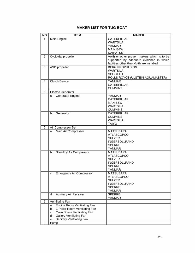
MAKER LIST FOR TUG BOAT NO ITEM MAKER 1 Main Engine CATERPILLAR
WARTSILA YANMAR MAIN B&W DAIHATSU
2 Cycloidal propeller Voith or other proven makers which is to be supported by adequate evidence in which facilities other than Voith are installed
3 ASD propeller BERG PROPULSION WARTSILA SCHOTTLE ROLLS ROYCE (ULSTEIN AQUAMASTER)
4 Clutch Device YANMAR CATERPILLAR CUMMINS
5 Electric Generator a. Generator Engine YANMAR
CATERPILLAR MAN B&W WARTSILA CUMMINS
b. Generator CATERPILLAR CUMMINS WARTSILA TAIYO
6 Air Compressor Set a. Main Air Compressor MATSUBARA
ATLASCOPCO SULZER INGERSOLLRAND SPERRE YANMAR
b. Stand by Air Compressor MATSUBARA ATLASCOPCO SULZER INGERSOLLRAND SPERRE YANMAR
c. Emergency Air Compressor MATSUBARA ATLASCOPCO SULZER INGERSOLLRAND SPERRE YANMAR
d. Auxiliary Air Receiver SPERRE YANMAR
7 Ventilating Fan a. Engine Room Ventilating Fan
b. Z-Peller Room Ventilating Fan c. Crew Space Ventilating Fan d. Gallery Ventilating Fan e. Sanitary Ventilating Fan
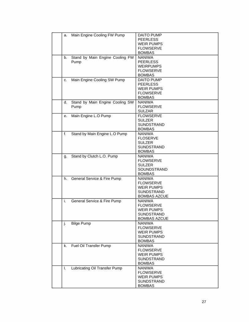
8 Pump
27
a. Main Engine Cooling FW Pump DAITO PUMP PEERLESS WEIR PUMPS FLOWSERVE BOMBAS
b. Stand by Main Engine Cooling FW Pump
NANIWA PEERLESS WEIRPUMPS FLOWSERVE BOMBAS
c. Main Engine Cooling SW Pump DAITO PUMP PEERLESS WEIR PUMPS FLOWSERVE BOMBAS
d. Stand by Main Engine Cooling SW Pump
NANIWA FLOWSERVE SULZAR
e. Main Engine L.O Pump FLOWSERVE SULZER SUNDSTRAND BOMBAS
f. Stand by Main Engine L.O Pump NANIWA FLOSERVE SULZER SUNDSTRAND BOMBAS
g. Stand by Clutch L.O. Pump NANIWA FLOWSERVE SULZER SOUNDSTRAND BOMBAS
h. General Service & Fire Pump NANIWA FLOWSERVE WEIR PUMPS SUNDSTRAND BOMBAS AZCUE
i. General Service & Fire Pump NANIWA FLOWSERVE WEIR PUMPS SUNDSTRAND BOMBAS AZCUE
j. Bilge Pump NANIWA FLOWSERVE WEIR PUMPS SUNDSTRAND BOMBAS
k. Fuel Oil Transfer Pump NANIWA FLOWSERVE WEIR PUMPS SUNDSTRAND BOMBAS
l. Lubricating Oil Transfer Pump NANIWA FLOWSERVE WEIR PUMPS SUNDSTRAND BOMBAS
28
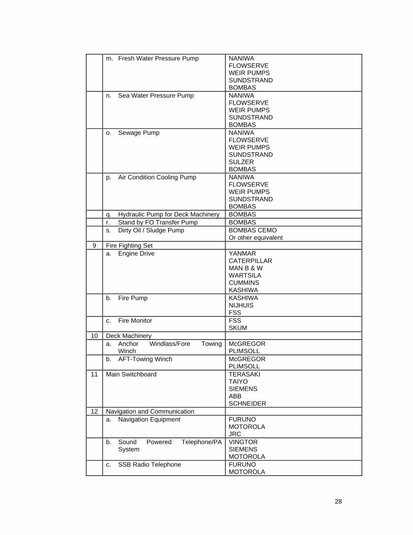
m. Fresh Water Pressure Pump NANIWA FLOWSERVE WEIR PUMPS SUNDSTRAND BOMBAS
n. Sea Water Pressure Pump NANIWA FLOWSERVE WEIR PUMPS SUNDSTRAND BOMBAS
o. Sewage Pump NANIWA FLOWSERVE WEIR PUMPS SUNDSTRAND SULZER BOMBAS
p. Air Condition Cooling Pump NANIWA FLOWSERVE WEIR PUMPS SUNDSTRAND BOMBAS
q. Hydraulic Pump for Deck Machinery BOMBAS r. Stand by FO Transfer Pump BOMBAS s. Dirty Oil / Sludge Pump BOMBAS CEMO
Or other equivalent 9 Fire Fighting Set a. Engine Drive YANMAR
CATERPILLAR MAN B & W WARTSILA CUMMINS KASHIWA
b. Fire Pump KASHIWA NIJHUIS FSS
c. Fire Monitor FSS SKUM
10 Deck Machinery a. Anchor Windlass/Fore Towing
Winch McGREGOR PLIMSOLL
b. AFT-Towing Winch McGREGOR PLIMSOLL
11 Main Switchboard TERASAKI TAIYO SIEMENS ABB SCHNEIDER
12 Navigation and Communication a. Navigation Equipment FURUNO
MOTOROLA JRC
b. Sound Powered Telephone/PA System
VINGTOR SIEMENS MOTOROLA
c. SSB Radio Telephone FURUNO MOTOROLA
29
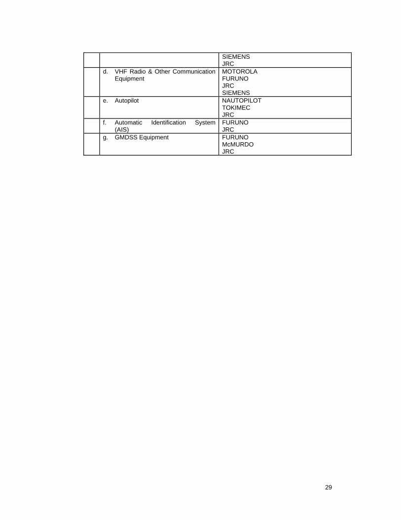
SIEMENS JRC
d. VHF Radio & Other Communication Equipment
MOTOROLA FURUNO JRC SIEMENS
e. Autopilot NAUTOPILOT TOKIMEC JRC
f. Automatic Identification System (AIS)
FURUNO JRC
g. GMDSS Equipment FURUNO McMURDO JRC