as_chap1
TRANSCRIPT

7/28/2019 as_chap1
http://slidepdf.com/reader/full/aschap1 1/10
1
1Engineering Graphics
Sections
• 1.1 The Importance of Engineering Graphics• 1.2 Engineering Graphics• 1.3 CAD• 1.4 Design and CAD• Key Terms
Objectives
• Describe visual thinking• Differentiate perspective, isometric, and orthographic projections• Understand the basis CAD
• Understand the relationship between design and CAD
7/28/2019 as_chap1
http://slidepdf.com/reader/full/aschap1 2/10
2 Chapter 1 Engineering Graphics
Overview
Engineering designs start as images in the mind’s eye of an engineer. Engineering
graphics has evolved to communicate and record these ideas on paper both two- and
three-dimensionally. In the past few decades, the computer has made it possible toautomate the creation of engineering graphics. Today engineering design and engineer-
ing graphics are inextricably connected. Engineering design is communicated visually
using engineering graphics.
1.1 THE IMPORTANCE OF ENGINEERING GRAPHICS
“Visualizing” a picture or image in your mind is a familiar experience. The image can be visualized at many different levels of abstraction. Think about light and you might seethe image of a light bulb in your “mind’s eye.” Alternatively, you might think about light versus dark. Or you might visualize a flashlight or table lamp. Such visual thinking isnecessary in engineering and science. Albert Einstein said that he rarely thought in words. Instead, he laboriously translated his visual images into verbal and mathematicalterms.
Visual thinking is a foundation of engineering. Walter P. Chrysler, founder of theautomobile company, recounted his experience as an apprentice machinist where hebuilt a model locomotive that existed “within my mind so real, so complete, that itseemed to have three dimensions there.” Yet, the complexity of today’s technology rarely permits a single person to build a device from his own visual image. The imagesmust be conveyed to other engineers and designers. In addition, those images must beconstructed in such a way that they are in a readily recognizable, consistent, and read-able format. This assuress that the visual ideas are clearly and unambiguously conveyedto others. Engineering graphics is a highly stylized way of presenting images of parts or
assemblies.A major portion of engineering information is recorded and transmitted usingengineering graphics. In fact, 92 percent of the design process is graphically based. Written and verbal communications along with mathematics account for the remainingeight percent. To demonstrate the effectiveness of engineering graphics compared to a written description try to visualize an ice scraper based on this word description:
An ice scraper is generally in the shape of a 140× 80 × 10 mm rectangular prism.One end is beveled from zero thickness to the maximum thickness in a length of 40 mm to form a sharp edge. The opposite end is semicircular. A 20 mm diameterhole is positioned so the center of the hole is 40 mm from the semicircular endand 40 mm from either side of the scraper.
It is evident immediately that the shape of the ice scraper is much more easily
visualized from the graphical representation shown in Figure 1.1 than from the worddescription. Humans grasp information much more quickly when that information is
presented in a graphical or visual form rather than as a word description.Engineering drawings, whether done using a pencil and paper or a computer, start
with a blank page or screen. The engineer’s mind’s eye image must be transferred to thepaper or computer screen. The creative nature of this activity is similar to that of an art-ist. Perhaps the greatest example of this is Leonardo da Vinci, who had exceptional engi-neering creativity devising items such as parachutes and ball bearings, shown in Figure

7/28/2019 as_chap1
http://slidepdf.com/reader/full/aschap1 3/10
Section 1.1 The Importance of Engineering Graphics 3
1.2, hundreds of years before they were re-invented. He also had exceptional artistic tal-ent, creating some of the most famous pictures ever painted such as Mona Lisa and The Last Supper .
Question 1
Figure 1.1
Figure 1.2 The creative genius of da Vinci is evident in these sketches of a parachute and a ball bearing, bothdevised hundreds of years before they were re-invented. (Parachute used with permission of the Biblioteca-Pina-coteca Ambrosiana, Milan, Italy. Property of the Ambrosian Library. All rights reserved. Reproduction is forbid-den. [The Inventions of Leonardo da Vinci, Charles Gibbs-Smith, Phaidon Press, Oxford, 1978, p. 24.] Ballbearing used with permission of EMB-Service for Publishers, Lucerne, Switzerland. [The Unknown Leonardo,edited by Ladislao Reti, McGraw-Hill, 1974, p. 286])
7/28/2019 as_chap1
http://slidepdf.com/reader/full/aschap1 4/10
4 Chapter 1 Engineering Graphics
1.2 ENGINEERING GRAPHICS
The first authentic record of engineering graphics dates back to 2130 BC, based on astatue now in the Museum of the Louvre, Paris. The statue depicts an engineer and gov-ernor of a small city-state in an area later known as Babylon. At the base of the statueare measuring scales and scribing instruments along with a plan of a fortress engraved
on a stone tablet.
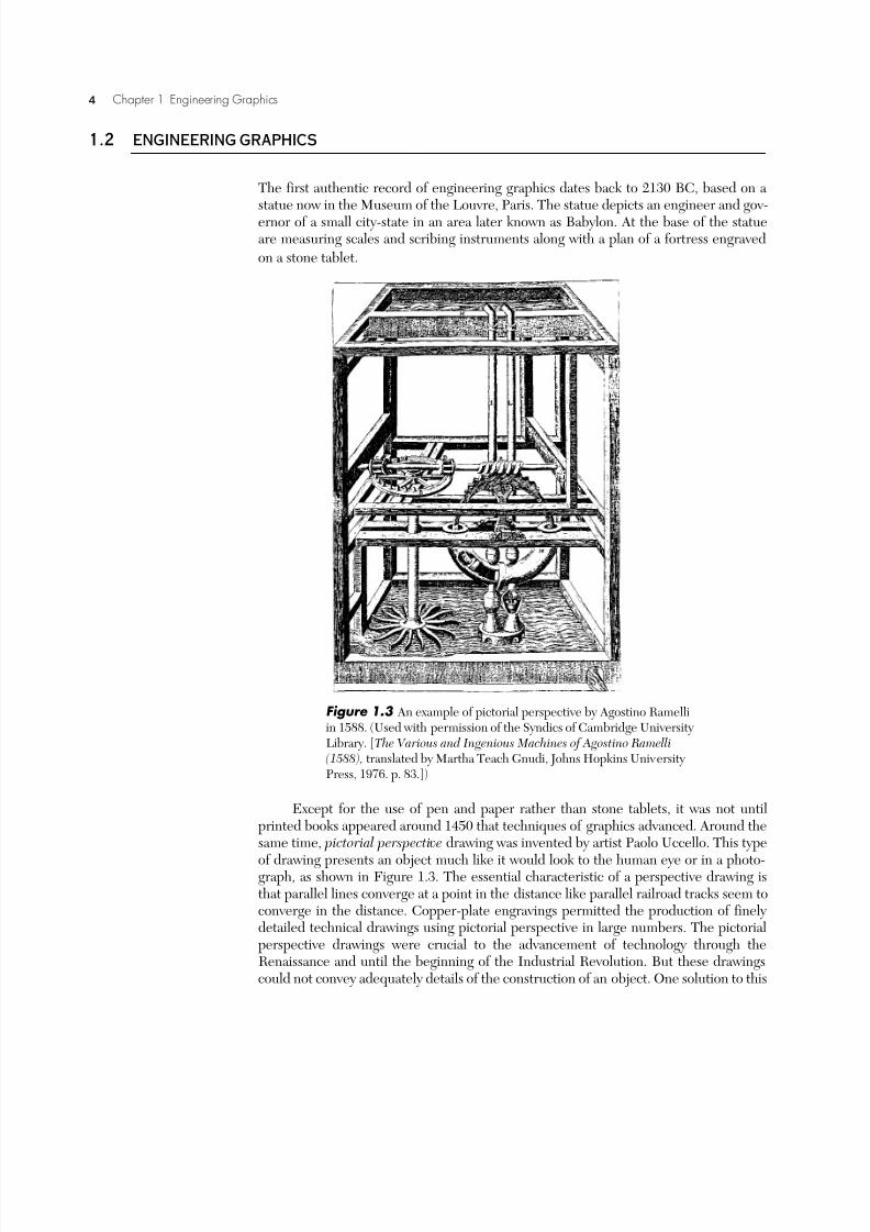
Except for the use of pen and paper rather than stone tablets, it was not untilprinted books appeared around 1450 that techniques of graphics advanced. Around thesame time, pictorial perspective drawing was invented by artist Paolo Uccello. This type
of drawing presents an object much like it would look to the human eye or in a photo-graph, as shown in Figure 1.3. The essential characteristic of a perspective drawing isthat parallel lines converge at a point in the distance like parallel railroad tracks seem toconverge in the distance. Copper-plate engravings permitted the production of finely detailed technical drawings using pictorial perspective in large numbers. The pictorialperspective drawings were crucial to the advancement of technology through theRenaissance and until the beginning of the Industrial Revolution. But these drawingscould not convey adequately details of the construction of an object. One solution to this
Figure 1.3 An example of pictorial perspective by Agostino Ramelliin 1588. (Used with permission of the Syndics of Cambridge University Library. [The Various and Ingenious Machines of Agostino Ramelli(1588), translated by Martha Teach Gnudi, Johns Hopkins University Press, 1976. p. 83.])

7/28/2019 as_chap1
http://slidepdf.com/reader/full/aschap1 5/10
Section 1.2 Engineering Graphics 5
problem was the use of the exploded view developed in the 15th century and perfectedby Leonardo da Vinci. The exploded view of an assembly of individual parts shows theparts spread out along a common axis, as shown for the hoist in Figure 1.4. Theexploded view reveals details of the individual parts along with showing the order in
which they are assembled.
The Industrial Revolution brought with it the need to tie more closely the concept
of a design with the final manufactured product using technical drawing. The perspec-tive drawing of a simple object in Figure 1.5a shows pictorially what the object lookslike. However, it is difficult to represent accurately dimensions and other details in aperspective drawing. Orthographic projections, developed in 1528 by German artistAlbrecht Dürer, accomplish this quite well. An orthographic projection typically showsthree views of an object. Each view shows a different side of the object (say the front,top, and side). An example of an orthographic projection is shown in Figure 1.5b.Orthographic projections are typically easy to draw, and the lengths and angles in ortho-
Figure 1.4 Assembled and exploded view of a hoist by Leonardo da Vinci, circa 1500. (Used with permission of the Biblioteca-Pinacoteca Ambrosiana, Milan, Italy. Property of the Ambrosian Library. All rights reserved. Reproduction is forbidden. [ The Inven-
tions of Leonardo da Vinci, Charles Gibbs-Smith, Phaidon Press, Oxford, 1978, p. 64.])

7/28/2019 as_chap1
http://slidepdf.com/reader/full/aschap1 6/10
6 Chapter 1 Engineering Graphics
graphic projections have little distortion. As a result, orthographic drawings can convey more information than a perspective drawing. But their interpretation takes more effortthan a pictorial perspective, as is evident from Figure 1.5. French philosopher andmathematician René Descartes laid the foundation for the mathematical principles of projections by connecting geometry to algebra in the 17th century. Much later GaspardMonge, a French mathematician, “invented” the mathematical principles of projectionknown as descriptive geometry. These principles form the basis of engineering graphicstoday. But because these principles were thought to be of such strategic importance,they remained military secrets until 1795. By the 19th century, orthographic projections were used almost universally in mechanical drawing, and they are still the basis for engi-
neering drawings today.
The isometric view is used more often today than the pictorial perspective view.Historically, it was used for centuries by engravers. Then in the early 19th century, Will-iam Farish, an English mathematician, formalized the isometric view and introduced itto engineers. The isometric view simplifies the pictorial perspective. In an isometric view, parallel lines remain parallel rather than converging to a point in the distance, asshown in Figure 1.5c. Keeping parallel lines parallel distorts the appearance of the
object slightly. But the distortion in an isometric view is negligible for objects of limiteddepth. For situations in which the depth of the object is large, such as an architectural view down a long hallway, the pictorial perspective is preferable. The advantage of theisometric view, though, is that it is much easier to draw than a pictorial perspective view.Question 1
1.3 CAD
The introduction of the computer revolutionized engineering graphics. Pioneers incomputer-aided engineering graphics envisioned the computer as a tool to replacepaper and pencil drafting with a system that is more automated, efficient, and accurate.The first demonstration of a computer-based drafting tool was a system calledSKETCHPAD developed at the Massachusetts Institute of Technology in 1963 by Ivan
Sutherland. The system used a monochrome monitor with a light pen for input from theuser. The following year IBM commercialized computer-aided drafting.
During the 1970s, computer-aided drafting blossomed as the technology changedfrom scientific endeavor to an economically indispensable industrial tool for design.Commands for geometry generators to create commonly occurring shapes were added.Functions were added to control the viewing of the drawing geometry. Modifiers suchas rotate, delete, and mirror were implemented. Commands could be accessed by typ-
Figure 1.5
7/28/2019 as_chap1
http://slidepdf.com/reader/full/aschap1 7/10
Section 1.4 Design and CAD 7
ing on the keyboard or by using a mouse. Perhaps most importantly, three-dimensionalmodeling techniques became a key part of engineering graphics software.
By the 1980s, computer-aided drafting became fully developed in the marketplaceas a standard tool in industry. In addition, the current technology of solids modelingcame about. Solids models represent objects in the virtual environment of the computer just as they exist in reality, having a volume as well as surfaces and edges. The introduc-tion of Pro/ENGINEER® in 1988 and SolidWorks® in the 1990s revolutionized com-puter-aided design and drafting. Today solids modeling remains the state-of-the-arttechnology.
What we have been referring to as computer-aided drafting is usually termedCAD, an acronym for Computer Aided Design, Computer Aided Drafting, or Com-puter Aided Design and Drafting. Originally the term Computer Aided Designincluded any technique that uses computers in the design process including drafting,stress analysis, and motion analysis. But over the last 35 years CAD has come to refermore specifically to Computer Aided Design and Drafting. Computer Aided Engineer-ing (CAE) is used to refer to the broader range of computer-related design tools.Question 1
1.4 DESIGN AND CAD
Inextricably connected with engineering graphics is the design process in which an engi-neering or design team faces a particular engineering problem and devises a solution tothat problem. Often the design team includes persons responsible for engineering,product design, production system design, manufacturing, marketing, and sales. Theidea is to simultaneously develop the product and the manufacturing process for theproduct. This is known as concurrent engineering or integrated product and processdesign. Key to the success of concurrent engineering is communication of information.Engineering graphics is one of the primary methods used by concurrent engineeringteams to record and transfer information during the design process.
The process of bringing a product to market is shown in Figure 1.6. The process
begins with the identification of a market, or user need. After this, the design process isthe key to bridging the gap between a user need and the manufacture and sales of aproduct. The design process can be broken down into three parts as indicated in Figure1.6. The first part is the specification of the problem. The design specification is a list of requirements that the final product must meet, including size, performance, weight,and so on. The second part of the design process is called ideation or conceptual design.In this phase, the design team devises as many ideas for solutions to the design problemas possible and then narrows them down to the best one based on the specification. Inmany cases, a designer or engineer will quickly sketch ideas to explore or communicatethe design concept to the rest of the design team. These freehand sketches form thebasis for the details of the design that are laid down in the third phase of the design pro-cess. It is in this last phase of the design process, known as detail design, that CAD iscrucial. The conceptual ideas for the product that were seen in a designer’s mind’s eye
or are on paper as rough sketches must then be translated into the visual language of engineering graphics. In this way, the ideas can be understood clearly and accurately by the design team and other designers, engineers, fabricators, suppliers, and machinists.It is in this phase of the design that the nitty gritty details have to be worked out. Shouldthe device be 30 mm long or should it be 35 mm long? How will one part fit withanother? What size hole should be used? What material should be used? What manu-facturing process will be used to make the part? The number of individual decisions that

7/28/2019 as_chap1
http://slidepdf.com/reader/full/aschap1 8/10
8 Chapter 1 Engineering Graphics
need to be made can be very large, even for a relatively simple part. Once the engineer-ing drawings have been created, the product can be manufactured and eventually sold.
The use of CAD has had a great impact on the design process. For example, a partmay be modified several times to meet the design specification or to mate with anotherpart. Before the advent of CAD, these modifications were very tedious, time-consum-ing, and prone to error. However, CAD has made it possible to make these changes rel-atively easily and quickly. The connectivity of computers using local area networks thenmakes the revised electronic drawings available to a team of engineers at an instant.This is crucial as engineering systems become more complex and operational require-ments become more stringent. For example, a modern jet aircraft has several million
individual parts that must all fit together and perform safely for several decades.Although CAD had a great impact on making the design process speedier and
more accurate, the capabilities of the first few generations of CAD were still limited.Early CAD systems only provided a means of automating the drafting process to createorthographic engineering drawings. The designer or engineer would simply generate aline on the computer screen rather than drawing the line on paper. Current computergraphics software such as “paint” or “draw” programs for personal computers work this way. As CAD became more sophisticated, it helped automate the drafting process basedon the “intelligence” of the software. CAD software lacking such intelligence requiredan engineer to draw a pair of parallel lines an exact distance apart by specifying coordi-nates of the endpoints of the lines. More advanced generations of CAD software per-mitted an engineer to draw approximately parallel lines using a mouse. Then theengineer would specify a particular distance between the lines and that the lines shouldbe parallel. The CAD software then automatically placed these lines the specified dis-tance apart and made them parallel. However, the major problem with the early gener-ations of CAD software was that the designer or engineer was simply creating two-dimensional orthographic views of a three-dimensional part using a computer instead of a pencil and paper. From these two-dimensional views, the engineer still needed toreconstruct the mind’s eye view of the three-dimensional image in the same way as if the drawings were created by hand.
Figure 1.6

7/28/2019 as_chap1
http://slidepdf.com/reader/full/aschap1 9/10
Section 1.4 Design and CAD 9
The current generation of CAD software has had a very profound effect on thedesign process, because it is now possible to create a virtual prototype of a part orassembly on a computer. For example, the solids model of a pizza cutter is shown in Fig-ure 1.7. Rather than translating a three-dimensional image from the mind’s eye to atwo-dimensional orthographic projection of the object, current CAD software starts with generating a three-dimensional virtual model of the object directly on the com-puter. This virtual model can be rotated so that it can be viewed from different angles.Several parts can be virtually assembled on the computer to make sure that they fittogether. The assembled parts can be viewed as an assembly or in an exploded view. Allof this is done in a virtual environment on the computer before the two-dimensionalorthographic engineering drawings are even produced. It is still usually necessary toproduce the orthographic engineering drawings. But these drawings only to serve as astandard means of engineering graphics communication, rather than as a tedious, time-consuming task necessary to proceed with the design process.
What Happened to Pencil and Paper Drawings?
CAD drawings have already replaced pencil and paper drawings. Through the 1970s and even intothe 1980s many engineering and design facilities consisted of rows and rows of drafting tables with adesigner or engineer hunched over a drawing on each table. Engineering colleges and universitiesrequired a full-year course in “engineering drafting” or “graphics communication” for all engineer-
ing students. Many of these students purchased a set of drawing instruments along with their firstsemester textbooks. They spent endless hours practicing lettering and drawing perfect circles.
Now nearly all of the drafting tables and drafting courses have been replaced by CAD. Onecan still find a drafting table here and there, but it is not for creating engineering drawings. Mostoften it is used for displaying a large CAD drawing to designers and engineers. They can make noteson the drawing or freehand sketch modifications on the drawing. The pencil is still an ideal meansfor generating ideas and quickly conveying those ideas to others. But eventually, all of the pencilmarkings are used as the basis for modifying the CAD drawing.
Figure 1.7
PROFESSIONAL SUCCESS
7/28/2019 as_chap1
http://slidepdf.com/reader/full/aschap1 10/10
10 Chapter 1 Engineering Graphics
In some companies with traditional products that have not changed for decades (like a spoonor a chair), pencil and paper drawings are gradually being converted into electronic form. In somecases, the original drawing is simply scanned to create an electronic version. The scanned drawingcannot be modified, but the electronic version takes much less storage space than a hard copy. Inother cases, the original pencil and paper drawings are being systematically converted to CADdrawings, so that they can be modified if necessary. In any case, though, the pencil and paper draw-ing is now just a part of the history of engineering.
Question 1
KEY TERMS
Problems
1. Research and report on an important historical figure in engineering graphics such asLeonardo da Vinci, Albrecht Dürer, Gaspard Monge, René Descartes, William Farish, M. C.Escher, Frank Lloyd Wright, Ivan Sutherland, or Paolo Uccello.
2. Using the World Wide Web, search for computer-aided design web sites. Report on the vari-ety of software available for CAD and its capabilities.
3. Trace the early development of CAD and report on your findings. A particularly useful start-ing point is an article by S. H. Clauser in the November 1981 issue of Mechanical Engineer-
ing.
4. Computer hardware and user interface development has had a profound effect on the evolu-
tion of CAD software. Research and report on the impact of the light pen, the graphics tablet,the direct view storage tube, raster graphics technology, the work-station computer, the per-sonal computer, or the mouse on the capability and evolution of CAD. (Many textbooks onengineering graphics discuss these items.)
5. Outline the design process and indicate how the three steps in the design process wouldrelate to:
a. the design of a suspension system for a mountain bike.
b. the design of an infant car seat.
c. the design of headphones for a portable cassette player.
d. the design of a squirrel-proof bird feeder
e. the design of a car-mounted bicycle carrier.
f. the design of children’s playground equipment.
CAD Engineering graphics Orthographic projections
descriptive geometry exploded view pictorial perspective
design process ideation specification
detail design isometric view