asce hec-ras seminar january 25, 2006 session 1b hydraulic data and fundamental behavior affected by...
TRANSCRIPT

ASCE HEC-RAS SeminarJanuary 25, 2006
Session 1BHydraulic Data and
Fundamental Behavior Affected by Uncertainty

Quote
Even if there is only one possible unified theory, it is just a set of rules and equations. What is it that breathes fire into the equations and makes a universe for them to describe?
The usual approach of science of constructing a mathematical model cannot answer the questions of why there should be a universe to describe. Why does the universe go to all the bother of existing?” Stephen Hawking

Topics of Session Review of Steady, Non-Uniform Flow
Flow Profiles Energy Losses
Selection of n-Values Understanding Variation
Effects of Uncertainty in Loss Calcs Uncertainty in Section Geometry Importance of Thresholds of Behavior

Uniform (Normal) Conditions vs Non-Uniform Conditions
In “normal” flow, the water surface is parallel to the bed slope and the EGL. This is not a normal occurrence. All flow profiles only approach normal depth asymptotically, and it can take a great distance for the depth to equal normal.
In non-uniform flow the depth changes so the water surface changes; we need to predict the change.

Specific Energy of Flow
Specific Energy, H is the flow energy measured W.R.T. the channel bottom:
H = d + V2/2gFor a wide channel, V =q/d, and so,
H = d + q2/2gd2
For a given flow then,q2/2g = d2(H-d)
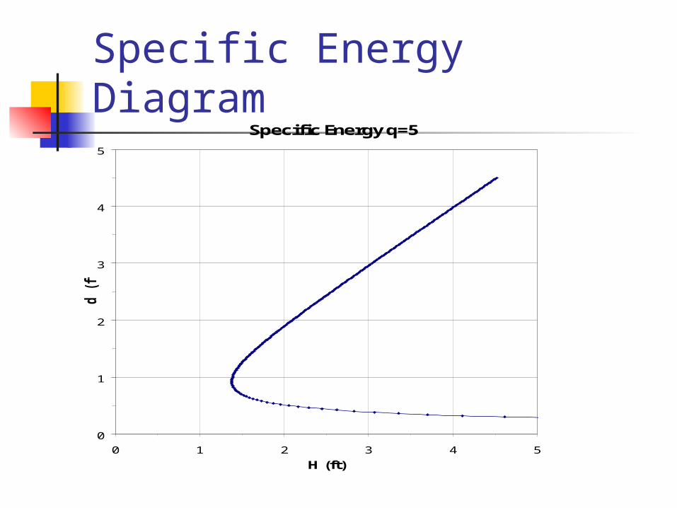
Specific Energy DiagramSpecific Energy q=5
0
1
2
3
4
5
0 1 2 3 4 5
H (ft)
d (
ft)

Specific Energy Diagram
Specific Energy Diagram
00.5
11.5
22.5
33.5
4
0 1 2 3 4 5 6 7
H (ft.)
De
pth
(ft
)
Energy 3cfsfEnergy 5cfsf
Critical Conditions
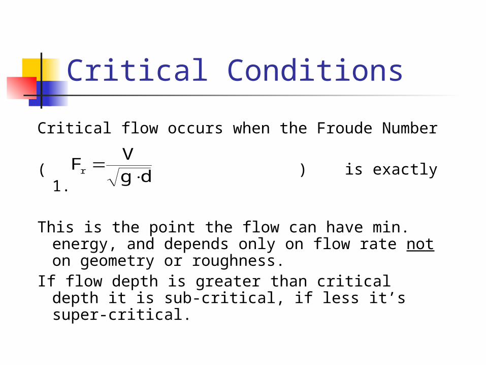
Critical flow occurs when the Froude Number
( ) is exactly 1.
This is the point the flow can have min. energy, and depends only on flow rate not on geometry or roughness.
If flow depth is greater than critical depth it is sub-critical, if less it’s super-critical.
dgV
Fr

Direction of Information Transfer
If flow is sub-critical (Fr < 1) the flow depth is affected upstream.
If the flow is super-critical (Fr > 1) the flow depth is affected downstream.
Toss a rock in the flow, if ripples move upstream against the flow it is sub-critical.
The Flow Regime also affects the changes in depth caused by channel transitions.

Channel Transitions In tranquil flow, a bottom change up
causes a depth reduction, a width decrease also causes a depth reduction.
In rapid flow, a bottom change down causes a small depth decrease and a width increase also causes a depth decease.
THIS BEHAVIOR IS COUNTER INTUITIVE! Make a quick sketch to see if the
behavior is possible

Specific Energy Diagram
Specific Energy q=5
0
1
2
3
4
5
0 1 2 3 4 5
H (ft)
d (
ft)
E1E2
ΔZ

For Channels That are NOT Wide
In any case where the width is less than about 10 times the depth, the use of the depth as the hydraulic radius is less accurate. In those cases use: V=Q/A Depth = A/Top Width ( the hydraulic
depth)
Thus the critical depth is determined from: g
Q
yA 2
h
c3
3
12
c gq
y
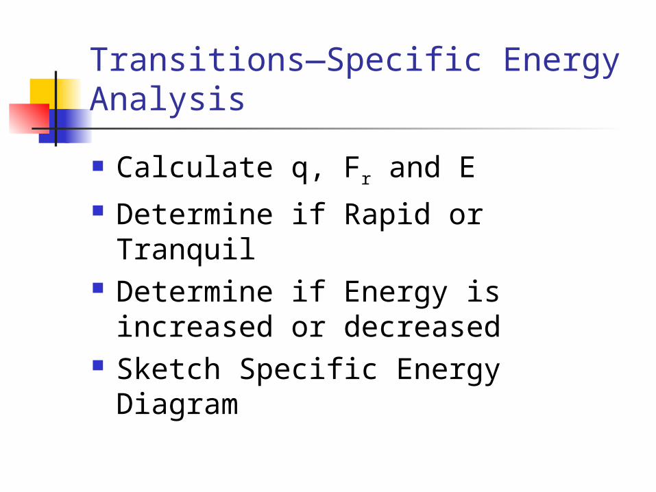
Transitions—Specific Energy Analysis
Calculate q, Fr and E Determine if Rapid or Tranquil Determine if Energy is increased or
decreased Sketch Specific Energy Diagram
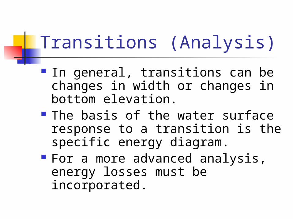
Transitions (Analysis) In general, transitions can be
changes in width or changes in bottom elevation.
The basis of the water surface response to a transition is the specific energy diagram.
For a more advanced analysis, energy losses must be incorporated.

Width ChangeSpecific Energy Diagram
00.5
11.5
22.5
33.5
4
0 1 2 3 4 5 6 7
H (ft.)
De
pth
(ft
)
Energy 3cfsfEnergy 5cfsf
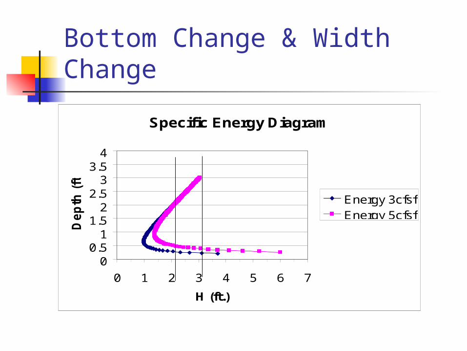
Bottom Change & Width Change
Specific Energy Diagram
00.5
11.5
22.5
33.5
4
0 1 2 3 4 5 6 7
H (ft.)
De
pth
(ft
)
Energy 3cfsfEnergy 5cfsf

Energy Analysis
The energy (for initial analysis) is assumed to be constant (no losses).
The energy equation provides:
222
22
121
21
22
1
1
Y2gY
qY
2gY
q
W
Qq channel wideof use theand
2g
V
2g
V22
YY

Solution in Simple Case
The equation allows calculation of depths, widths, velocities, energies or flow, depending on what is given. The definition of continuity, energy and elevation is often combined with the energy equation to get a solution.

Simple Example
If the flow is 30 cfs in a 10 ft wide channel with a depth of 3 ft and the width changes to 6 ft at the same time as the bottom is raised one ft, what is the depth and change in WSEL?
1YY4.64
253
94.64
92
908.1Y

Hydraulic Jump
The only way flow can cross from super-critical to sub-critical regimes is through a hydraulic jump.
The location of a jump is determined be the relationship of the sequent depth to the incoming flow depth.
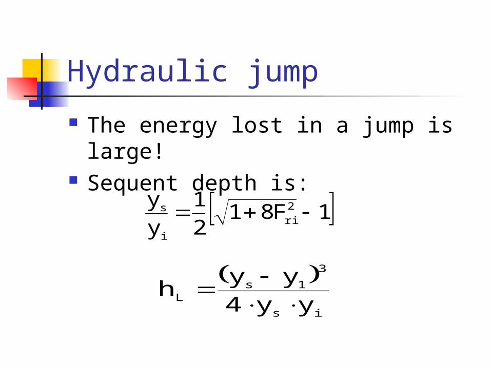
Hydraulic jump
The energy lost in a jump is large! Sequent depth is:
1F8121
y
y 2
ri
i
s
is
3
1sL yy4
yy h

Specific Energy of Jump
Specific Energy q=5
0
1
2
3
4
5
0 1 2 3 4 5H (ft)
d (ft)
#REF!
ys
yi
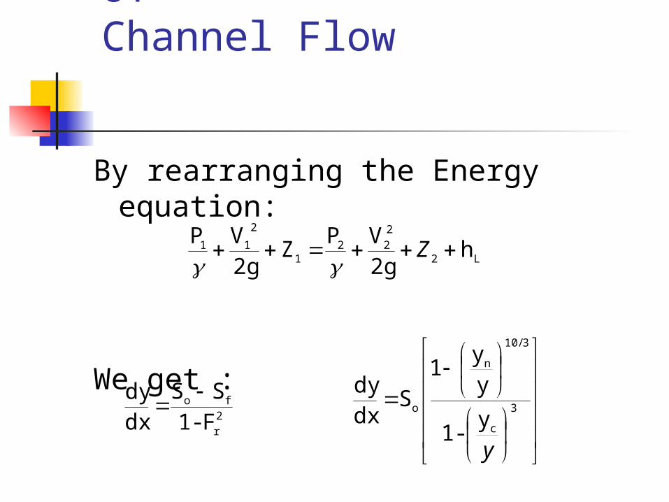
Differential Equation of Channel Flow
By rearranging the Energy equation:
We get :
L2
2
221
2
11 h2gVP
Z2gVP Z
2
r
fo
F-1
SS
dxdy
3
c
3/10
n
oy
-1
yy
1
S dxdy
y

The Gradually Varied Flow Profiles
The profile depends on: The ratio of flow depth to normal depth The ratio of flow depth to critical depth The bed slope
Sustaining Mild Steep Critical
Non-Sustaining Adverse Horizontal

Flow Profiles Draw critical and normal depth on
channel profile, number zones from outer zone
Mild yn > yc M1, M2, M3 Steep yn< yc S1, S2, S3 Critical yn = yc C1, C2, C3
Horizontal no normal H2, H3 Adverse no normal A2, A3

The Differential Equation of Non-Uniform Flow solved by steps:
For channels with regular geometry the profile is calculated by balancing the energy equation for an assumed water depth. Resulting is a calculated distance along the channel to the point where the assumed depth will occur. This is “Direct Step”.

Equations
2
2/3
av
avavf
of
12
2
11
2
22fo
Lf
21o
L
2
222
2
111
R1.49
VnS
SSHH
x
2gV
y2gV
yxSS
xh
S xzz
S
h2gV
yZ2gV
yZ

Conditions Conditions
Rectangular 20 ft. wide channel with Rectangular 20 ft. wide channel with slope of 0.0005 and an n-value of 0.018 slope of 0.0005 and an n-value of 0.018 conveying 800 cfs, ends at an abrupt conveying 800 cfs, ends at an abrupt dropdrop
Yn=8.01
Yc=3.68Y(x)
4yc
.7yc
M2

Calculations
y A R V H dH Rav Vav Sf*k dX X
3.68 73.6 2.68 10.9 5.52 - - - - - 15
4.68 93.6 3.19 8.6 5.82 .3 2.94 9.71 3.27 108 123
5.68 113. 3.62 7.0 6.45 .63 3.41 7.79 1.72 518 641
6.68 133 4.00 6.0 7.24 .79 3.81 6.52 1.04 1449 2090
7.68 153 4.34 5.21 8.10 .86 4.17 5.60 6.82 4750 6840
7.93 158 4.42 5.0 8.32 .23 4.38 5.13 5.36 6212 13052
Numerical Sensitivity?
What id the steps in Water depth were 0.5 ft?
0.01 ft? How close is close enough?

Roughness Estimates
For lined channels the theoretical description of flow behavior is useful. Manning’s n-values, f, C and CH can be used.
There is little advantage to not using n-values but f and C are more fundamentally correct
Roughness
It it essential to recognize that open channel flow has variable flow geometry rather than only variable velocity (as in a pipe). Thus, the relative roughness (ks/D) changes.
As the roughness changes so does the n-value (f and C also).

Roughness Roughness has components that
are considered separately: 2-28 River Engineering
Channel material Vegetation Alignment Channel Irregularity Channel Variation

Roughness Factors
where: no = Base value for straight uniform channels n1 = Additive value due to cross-section irregularity n2 = Additive value due to variations of the channel n3 = Additive value due to obstructions n4 = Additive value due to vegetation m5 = Mulitiplication factor due to sinuosity
543210 )( mnnnnnn

Channel Roughness Catalogs
“Rules of Thumb ” Textural catalogs Photographic Catalogs of measured
roughness values USGS Barnes REMEMBER the boundary
roughness can change from bed-form changes induced by the flow.

Barnes

Barnes 2

Barnes 3

Dealing With Roughness Uncertainty
Some Engineers have told me “n-value you pick doesn’t matter, nobody knows the correct number”… WTF, over??????
I use a range of reasonable values to calculate how the variables you are examining change with roughness changes.
Does your decision change?? What is Sensitivity of your situation to the
uncertainty?

Compound Channels
In most real channels the change of channel area as the depth changes is not a smooth function. There are frequently floodplains where width increases enormously with a small change in depth.
These situations are called compound channels.

Channel Geometry

Analysis

Analysis
Sub-sections of the channel are identified with a zone of equal n-value.
Water-to-water shear is neglected. Energy slope is the same for all
zones. Sum of sub-section discharge is
total discharge.

Alternative Analysis
Would “average” n-value over entire channel be acceptable? When ? Why?
What is influence of neglecting the water-to-water shear??
What is a practical limit to sub-section division?
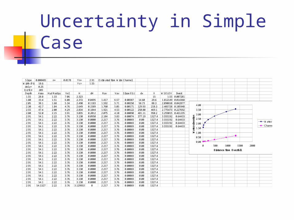
Uncertainty in Simple Case
Slope 0.000485 n= 0.0178 Yn= 2.91 Estimated from Wide ChannelWidth (Ft) 18.6 Yc= 1.55
del y= 0.25Q(cfs)= 203Depth Area Hyd Radius Vel H dH Rav Vav Slope EGL dx X WSELEV Invert1.55 28.8 1.33 7.06 2.323 15 1.55 0.0072811.80 33.4 1.51 6.08 2.372 0.0495 1.417 6.57 0.00387 14.60 29.6 1.812149 0.0143682.05 38.1 1.68 5.34 2.490 0.1183 1.592 5.71 0.00250 58.73 88.3 2.090658 0.0428772.30 42.7 1.84 4.76 2.649 0.1589 1.760 5.05 0.00171 129.93 218.3 2.403728 0.1059482.55 47.4 2.00 4.29 2.834 0.1844 1.921 4.53 0.00122 250.80 469.1 2.775473 0.2276922.80 52.0 2.15 3.91 3.035 0.2012 2.075 4.10 0.00090 481.11 950.2 3.259015 0.4612352.91 54.1 2.22 3.76 3.130 0.0950 2.184 3.83 0.00074 377.19 1327.4 3.555192 0.644332.91 54.1 2.22 3.76 3.130 0.0000 2.217 3.76 0.00069 0.00 1327.4 3.555192 0.644332.91 54.1 2.22 3.76 3.130 0.0000 2.217 3.76 0.00069 0.00 1327.4 3.555192 0.644332.91 54.1 2.22 3.76 3.130 0.0000 2.217 3.76 0.00069 0.00 1327.4 3.555192 0.644332.91 54.1 2.22 3.76 3.130 0.0000 2.217 3.76 0.00069 0.00 1327.42.91 54.1 2.22 3.76 3.130 0.0000 2.217 3.76 0.00069 0.00 1327.42.91 54.1 2.22 3.76 3.130 0.0000 2.217 3.76 0.00069 0.00 1327.42.91 54.1 2.22 3.76 3.130 0.0000 2.217 3.76 0.00069 0.00 1327.42.91 54.1 2.22 3.76 3.130 0.0000 2.217 3.76 0.00069 0.00 1327.42.91 54.1 2.22 3.76 3.130 0.0000 2.217 3.76 0.00069 0.00 1327.42.91 54.1 2.22 3.76 3.130 0.0000 2.217 3.76 0.00069 0.00 1327.42.91 54.1 2.22 3.76 3.130 0.0000 2.217 3.76 0.00069 0.00 1327.42.91 54.1 2.22 3.76 3.130 0.0000 2.217 3.76 0.00069 0.00 1327.42.91 54.1 2.22 3.76 3.130 0.0000 2.217 3.76 0.00069 0.00 1327.42.91 54.1 2.22 3.76 3.130 0.0000 2.217 3.76 0.00069 0.00 1327.42.91 54.1 2.22 3.76 3.130 0.0000 2.217 3.76 0.00069 0.00 1327.42.91 54.1 2.22 3.76 3.130 0.0000 2.217 3.76 0.00069 0.00 1327.42.91 54.1 2.22 3.76 3.130 0.0000 2.217 3.76 0.00069 0.00 1327.42.91 54.1 2.22 3.76 3.130 0.0000 2.217 3.76 0.00069 0.00 1327.42.91 54.1 2.22 3.76 3.130 0.0000 2.217 3.76 0.00069 0.00 1327.42.91 54.1 2.22 3.76 3.130 0.0000 2.217 3.76 0.00069 0.00 1327.42.91 54.1327 2.22 3.76 3.129953 0 2.217 3.76 0.00069 0.00 1327.4
0.00
0.50
1.00
1.50
2.00
2.50
3.00
3.50
4.00
0 500 1000 1500 2000
Distance from Overfall
Wat
er e
leva
tio
n
Water Surface
Channel Invert

For Channels that Are NOT Regular – Standard Step.
For channels that are irregular, the cross-sections are located at given positions. Therefore, a guess is made of the water level at the next section. Based on that guess the energy loss is calculated, the calculated water level is then compared to the guess, and the guess updated until an acceptable ‘closure’ at that section is obtained.

Standard Step Data
Standard Step Calculations All irregular channels require the use of
standard step. Because the calculations of the energy loss is tedious the method is best computerized.
There are many issues to consider in the calculation scheme. TOTAL Head Loss Average Roughness in Each location and
between sections
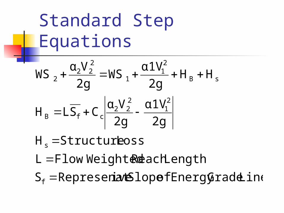
Standard Step Equations
Line GradeEnergy of Slope iveRepresenatS
LengthReach WeightedFlowL
LossStructureH
2g
α1V
2g
VαCSLH
HH2g
α1VWS
2g
VαWS
f
s
21
222
cfB
sB
21
1
222
2

Standard Step Calculation Procedure
Beginning at known conditions, guess Y2, with channel shape calculate V2, then S2, and solve for what Y2 satisfies the original energy equation. If guess and calculated value are the “same”, that is “correct” answer. Otherwise guess again.

The Limitations of Standard Step Method
1. Gradually Varied because hydrostatic Pressure is assumed
2. One-Dimensional3. Steady because no time term is
present4. Small channel Slope (10%-20%)
because y and H are assumed collinear.

Homework
Look at the following publications in the references CD: The origin and Derivation of Ia/S in the
Runoff Curve Number System NEH Part 630 Hydrology and HEH 4 (old) HEC-HMS Documentation Basic Hydraulic Principles River Engineering