asce 41‐13 hands‐on approach analysis provisions part 02-asce_41_analysis... · asce 41‐13...
TRANSCRIPT
ASCE 41‐13 Hands‐On Approach Analysis Provisions
SEAU 5th Annual Education Conference 1
ASCE 41-13 Analysis ProvisionsRobert Pekelnicky, PE, SE
Principal, Degenkolb EngineersChair, ASCE 41 Committee*
*The view expressed represent those of the author, not the standard’s committee as a whole.
Identify the primary and secondary components
Displacement-based analysis provisions
Capacity-based design philosophy
Tie the building together
Three tiers of evaluation and retrofit
ASCE 41-13 Analysis Procedures
2
(not just the tables and equations)
Read the Standard!

ASCE 41‐13 Hands‐On Approach Analysis Provisions
SEAU 5th Annual Education Conference 2
Which elements are primary and which are secondary?
Primary & Secondary Elements
Main lateral force resisting system elements
Must be included in the analysis
Can be new or existing elements
Expected to sustain inelastic deformations (if possible)
Primary Components
Support gravity loads
Do not contribute significantly to the lateral strength and/or stiffness
Typically existing elements
Can yield provided gravity load support not lost
Can be left out of main linear analytical model
Must accommodate structures deformations – commonly using a separate model
Must be included in a nonlinear model
Secondary Components
ASCE 41‐13 Hands‐On Approach Analysis Provisions
SEAU 5th Annual Education Conference 3
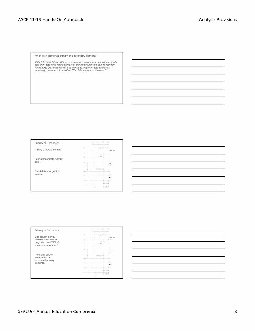
“If the total initial lateral stiffness of secondary components in a building exceeds 25% of the total initial lateral stiffness of primary components, some secondary components shall be reclassified as primary to reduce the total stiffness of secondary components to less than 25% of the primary components.”
When is an element a primary or a secondary element?
Primary or Secondary
7-Story Concrete Building
Perimeter concrete moment frame
Flat-slab interior gravity framing
Primary or Secondary
Slab-column gravity systems resist 54% of longitudinal and 72% of transverse base shear!
Thus, slab-column frames must be considered primary elements.

ASCE 41‐13 Hands‐On Approach Analysis Provisions
SEAU 5th Annual Education Conference 4
Primary or Secondary – Concrete Buildings
Shear walls and associated collectors are primary elements.
Moment frames are typically primary elements.
Gravity moment frames and slab-column frames may be primary or secondary.
Primary or Secondary – Steel Buildings
Braced frames and moment frames, along with associated collectors, are primary elements.
Beam-column gravity framing is secondary.
Primary or Secondary – Wood Buildings
Plywood sheathed walls are primary elements.
Other sheathing material may or may not be primary.

ASCE 41‐13 Hands‐On Approach Analysis Provisions
SEAU 5th Annual Education Conference 5
Shall be considered structural elements if their stiffness exceeds 10% of the total stiffness of the primary system at that story
Precast concrete cladding in steel or concrete moment frame buildings is a common example
Nonstructural as Structural
Pseudo-lateral force displaces structure to an approximation of the maximum displacement envelope.
Displacement-Based Design
F5
F4
F3
F2
F1
VGround Moves
Ω0SaW/(R/I)
Displacement
Elastic Response
Inelastic Structural Response
SaW/(R/I)
For
ce
CdΔeΔe
ASCE 7 Design – Forced Based

ASCE 41‐13 Hands‐On Approach Analysis Provisions
SEAU 5th Annual Education Conference 6
CmSaW
Displacement
C1C2
V = C1C2CmSaWPseudo Lateral Force
Elastic Response
Inelastic Structural Response
Expected Maximum (Target) Displacement (t = C0C1C2Sd)
Yield Capacity, or QCE
For
ce
Sd
ASCE 41 - Displacement Based Design
5
F5
F4
F3
F2
F1
VGround Moves
If the pseudo-lateral force, V, displaces the structure to its maximum envelope, the demand on a deformation controlled action, Qud, predicts the maximum inelastic deformation of that component’s action.
t
V
u
Qud
Qce
y
Displacement / Rotation
For
ce /
Mom
ent
u
Qud
Qce
CP,sy LS,s
CP,pLS,pIO,p/s
CP,s= 0.75CP,s
CP,p= 0.75CP,p
IO,p= 0.67CP,p
mIO= 0.75IO,p/y
mLS,p= 0.75LS,p/y
mCP,p= 0.75CP,p/y
mLS,s= 0.75LS,s/y
mCP,s= 0.75CP,s/y
Displacement Based Design – Element Level

ASCE 41‐13 Hands‐On Approach Analysis Provisions
SEAU 5th Annual Education Conference 7
Secondary elements must be checked at maximum displacement of primary elements in linear procedures for earthquake induced deformations and gravity loads.
Different, larger, m-factors for secondary elements are provided.
Secondary elements MUST be modeled in nonlinear analysis per Section 7.2.3.3.
Mathematical models for use with nonlinear procedures shall include the stiffness and resistance of primary and secondary components. The strength and stiffness degradation of primary and secondary components shall be modeled explicitly.
Deformation Compatibility
Can include secondary elements in model or
Determine displacements of primary elements from main model, then displace secondary elements in a separate model to same displacements
V
F5
F4
F3
F2
F1
Deformation Compatibility
Capacity-Based Design

ASCE 41‐13 Hands‐On Approach Analysis Provisions
SEAU 5th Annual Education Conference 8
Capacity-Based Design – Desired Response
Compression brace buckles
Tension brace yields
Capacity-Based Design – Undesirable Response
Connection fractures
ASCE 41 aims to prevent brittle force-controlled elements from failing before ductile deformational-controlled elements yield.

ASCE 41‐13 Hands‐On Approach Analysis Provisions
SEAU 5th Annual Education Conference 9
Designate specific elements to yield, which are called deformation-controlledelements
Every other element of the structure should not yield, rupture, or otherwise fail, those are called force-controlled elements
Structure dissipates seismic energy through controlled yielding of deformation-controlled elements
No brittle failures in force-controlled elements occur which could lead to instability
Capacity-Based Design
Capacity-Based Design – Example
Column
Collector Beam
Brace
Capacity-Based Design – Example
Columns can be def-cont. or force-cont.
Collectors can be def-cont. or force-cont.
Brace
Connections almost always force-contr.
Foundation elements almost always force-contr.
Soil actions can be def-cont. or force-cont.
Beam supporting “V” or chevron brace force-cont.

ASCE 41‐13 Hands‐On Approach Analysis Provisions
SEAU 5th Annual Education Conference 10
Capacity-Based Design – Example
Connections are almost always force-controlled actions.
Steel moment frame construction and wood frame construction are the main exceptions, where connections are permitted be the yielding mechanism.
Another rare exception is in braced frames if there is explicit modeling and research to support ductile behavior.
Linear Static Procedure (LSP)
Linear Dynamic Procedure (LDP)
Modal response spectrum
Linear response history procedure
Nonlinear Static Procedure (NSP) –aka “pushover”
Nonlinear Dynamic Procedure –aka nonlinear response history
ASCE 41-13 Analysis Provision
Linear Analysis Procedures
V = C1C2CmSaW
Apply the psuedo-lateral force, Fx, to each story to get the earthquake action demand, Qe.
∑V (same as ASCE 7)
ASCE 41‐13 Hands‐On Approach Analysis Provisions
SEAU 5th Annual Education Conference 11
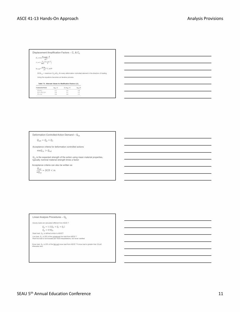
Displacement Amplification Factors – C1 & C2
DCRmax = maximum Qud/κQce for every deformation controlled element in the direction of loading.
Using the equations becomes an iterative process.
Deformation-Controlled Action Demand – Qud
Acceptance criteria for deformation controlled actions
Acceptance criteria can also be written as
Qce is the expected strength of the action using mean material properties, typically nominal material strength times a factor
Linear Analysis Procedures – Qg
Gravity loads are calculated different from ASCE 7.
1.1
Dead load, QD, is defined similar to ASCE7.
0.9
Live load, QL, is 25% of the unreduced live load from ASCE 7.Roof live load is not included per most interpretations, but never clarified.
Snow load, QS, is 20% of the flat roof snow load from ASCE 7 if snow load is greater than 30 psf, otherwise zero.

ASCE 41‐13 Hands‐On Approach Analysis Provisions
SEAU 5th Annual Education Conference 12
Factor to account for uncertainty in collection of as-built information.
κ = 0.75 or 1.0, depending on data collection requirements.
Additional value of κ = 0.90 for minimum data collection with material strengths listed in design documents, if:
Life Safety or lower performance level, and
Linear analysis procedures.
Knowledge Factor - κ
Specific requirements for testing are found in the material chapters for each element.
Material Testing Requirements
Force-Controlled Action Demand – Qf
Demands for force-controlled actions shall be taken as:
1. The maximum action that can be developed in a component based on a limit-state analysis considering expected strengths of the components delivering force or the maximum actions developed in a component as limited by nonlinear response of the building.
2. Alternatively, shall be calculated as
Acceptance criteria for deformation controlled actions
Qcl is the lower-bound of the action using mean material properties, typically nominal material strengths.

ASCE 41‐13 Hands‐On Approach Analysis Provisions
SEAU 5th Annual Education Conference 13
ASCE 41-17 Change – Qf
= 1.3 for Life Safety and greater performance level = 1.0 for Collapse Prevention performance level
Concern that the defined margin of safety provided by the Life Safety performance level was not being met with current procedures, because a there was no difference in force-controlled acceptance criteria led to:
J factor is intended to reduce Qe to the magnitude elements see while the structure is yielding.
Two options to determine J:1. Smallest DCR in the load path delivering force to the force-controlled element
2. Default values: 2.0 for High seismicity, 1.5 for Moderate seismicity, and 1.0 for Low seismicity.
Caveat on item 2 that defaults to J = 1.0 if the load path is elastic.
Linear Analysis Procedures – J factor
IMPORTANT – If load path is elastic or if deformation-controlled elements DCRs or m-factors are less than 2.0, assuming J = 2.0 is UNCONSERVATIVE

ASCE 41‐13 Hands‐On Approach Analysis Provisions
SEAU 5th Annual Education Conference 14
Linear Analysis Procedures – ASCE 7
2 story CBF BuildingW1 = W2 = 2,000k W = 4,000 kSDS = 1.0T = 0.35 s
R = 3.25I = 1.25
V = 1.0*4,000 / (3.25/1.25)V = 1,500 kips
Linear Analysis Procedures – ASCE 41
2 story CBF BuildingW1 = W2 = 2,000k W = 4,000 kSDS = 1.0T = 0.35 s
C1C2 = 1.1 for older braces with m = 4
Cm = 1.0
V =1.1*1.0*1.0*4,000 V = 4,400 kips
ASCE 7 V = 1,500 kips
Linear Analysis Procedures – ASCE 7 vs. ASCE 41
F ASCE 7BraceF = 750kPu = 433k
Brace HSS 9x9x1/2
CompressionϕPn = 443k
DCR = 433/443 = 0.98
TensionϕTn = 633k
DCR = 433/633 = 0.68
ASCE 41BraceF = 2,200kQud = 1,300k
Brace HSS 9x9x1/2
Compression Qce = 1.1*Pn = 541k
DCR = 1,300/541 = 2.4
m = 3.1 > DCR ok
TensionQuf = FyeAg
Quf = 1.1*46*15.3 = 774k
DCR = 1,300/774 = 1.7
m = 3.1 > DCR ok

ASCE 41‐13 Hands‐On Approach Analysis Provisions
SEAU 5th Annual Education Conference 15
Linear Analysis Procedures – ASCE 7 vs. ASCE 41
F ASCE 7CollectorF = 750kPu = Ω0F = 2*750Pu = 1,500 k
ConnectionPu = Capacity of bracePu = RyFyAg
Pu = 1.1*46*15.3 = 774k
Check against ϕPn
ASCE 41CollectorF = 2,200kQuf = Qe/(C1*C2*J)J = DCRmin = 1,300/774 = 1.7(note J = 2 could be used but would be UNCONSERVATIVE)
Quf = 2,200/(1.1*1.7) = 1,170k
ConnectionQuf = Capacity of braceQuf = 774k
OrQuf = Qe/(C1*C2*J)Quf = 1,300/(1.1*1.7)Quf = 700 k
Check against Pn
Less than capacity because of issue with C1*C2 being double counted
No floor on the force level as there is in ASCE 7
No limit on period like in ASCE 7
C1C2 factors should be applied to all analysis results before checking component actions
For LDP Qe = C1C2 times analysis output force or
Response spectra input into model should be multiplied by C1C2
Notes on Modal Analysis - LDP
Not permitted for two defined types of irregularity
Weak Story – Total DCR above less than 125% Total DCR below
Torsion – Total DCR on one side of center of rigidity 150% Total DCR on the other side
Unless all DCR < 3.0 and associated component m-factor
Limitations on Use of Linear Procedures

ASCE 41‐13 Hands‐On Approach Analysis Provisions
SEAU 5th Annual Education Conference 16
Top and middle stories
(2.5*60k+1.5*60k)/120k = 2.0
Bottom Story
(4.0*150k + 2.0*150k)/300k = 3.0
DCRBot > 1.25*DCRMid
If all DCRs had been 50% of what was shown, linear procedures would have been ok
Weak Story
Torsion
Red Dot = Center of Rigidity
North frame DCR = 5.0
South Frame 1 DCR = 1.5
South Frame 2 DCR = 1.5
DCR North / South = 5/1.5 = 3.3
Torsional Irregularity Exists
Linear Static Procedure not permitted when:
T greater than 3.5Ts
Abrupt changes in lateral system dimensions
Soft story condition
Story torsional stiffness irregularity
Nonorthogonal lateral systems
Limitations on Use of Linear Procedures

ASCE 41‐13 Hands‐On Approach Analysis Provisions
SEAU 5th Annual Education Conference 17
MOT = 300*40+200*27+100*14 = 18,800 k-ft
Ms = 3*70*30 = 6,300 k-ft
DCR = 18,800/(0.9*6,300) = 3.3
OT = 0.5*(4+8) = 6 > DCR
300k
200k
100k
70k /floor
Overturning
Strength capacities, not allowable capacities
qc = 3qallow for shallow & 1.5qallow for deep
Bearing capacity and pile plunging are deformation-controlledm factors IO=1.5, LS=3, CP=4 for fixed basem factors vary for flexible base (w/ soil springs)
Physical foundation element (i.e. footing or pile) is force-controlled
Foundation Provisions
Qud = (300*40+200*27+100*14)/30 + 1.1*(3*70+0.25*3*72) = 920 k
6’x6’ footing
qallow = 3,000 psf
qc = 3*3,000 = 9,000 psf
Qce = 6*6*9 = 324 k
DCR = 920 / 320 = 2.9
m = 0.5*(1.5+3) = 2.3 < DCR => NG
Could revise model to include soil springs and get a larger m-factor or retrofit by tying footings together
300k
200k
100k
70k /floor
Foundation Provisions

ASCE 41‐13 Hands‐On Approach Analysis Provisions
SEAU 5th Annual Education Conference 18
Check punching shear
Quf = [(300*40+200*27+100*14)/30]/2.9+ 1.1*(3*70+0.25*3*72) = 506 k
Divided by 2.9 as C1C2J
300k
200k
100k
70k /floor
Foundation Provisions
SSI is a means by which the response spectrum parameters can be reduced because of properties of the foundation and soil affect the seismic response
Foundation Damping
Kinematic Interaction Effects
Base Slab Averaging
Embedment
Soil Structure Interaction
If SSI is used to reduce forces, the following conditions must be met
Horizontal and vertical soil springs are included in model
Foundation is tied together with mat or slab on grade that is not flexible compared to the vertical elements
Site parameters, vs30, are know
Soil Structure Interaction

ASCE 41‐13 Hands‐On Approach Analysis Provisions
SEAU 5th Annual Education Conference 19
If SSI is used to reduce forces, the following conditions must be met
Horizontal and vertical soil springs are included in model
Foundation is tied together with mat or slab on grade that is not flexible compared to the vertical elements
Site parameters, vs30, are know
Soil Structure Interaction
Be wary of reductions that seem too big, i.e. 30% or more
Nonlinear Static Procedure
Displace the structure to the maximum estimated roof displacement
Permit yielding and force redistribution
Evaluate nonlinear deformation of each component versus specified limits
Nonlinear Dynamic Procedure
Use actual or simulated EQ ground motions
Simulates structures response to the earthquake
Evaluate nonlinear deformation of each component versus specified limits
Nonlinear Analysis Procedures
NSP vs. NDP
NSP permitted to be used when μstrength < μmax and higher mode effects are not significant
Deformation-controlled actions must be modeled
Material chapters with modelingparameters and deformation limits
Force-Controlled Actions
Capacity based design (limit state analysis) or maximum force from model
Nonlinear Analysis Procedures

ASCE 41‐13 Hands‐On Approach Analysis Provisions
SEAU 5th Annual Education Conference 20
Nonlinear Static Pushover
Longitudinal Pushover Curve
0
500
1000
1500
2000
2500
3000
3500
4000
0.00 10.00 20.00 30.00 40.00
Displacement [in.]
Bas
e S
he
ar [
kip
s]
Roof Disp. = 1.5"- Both Stair Walls Flex Yield @ Base- All Elev. Core Coupling Beams Yield- Airshafts @ G-Line Flex. Yield @ 2nd Fl.
Roof Disp. = 4"- Elev Cores Flex Yield @ 3rd Fl.- Airshafts @ E-Line Flex Yield.
Roof Disp = 9"- G-Line Col. Flex. Yield Below Roof, 9th, & 8th- Cont Stair Core Pass IO Limit- Discont. Stair Core Pass LS Limit- Interior Beam Flex Yielding
Roof Disp. = 7"- Col. Lap Splice Pass LS Limit
Roof Disp. = 10"- Elev. Cores Pass IO Limit- G-Line Col Flex. Yield Below 7th
BSE-1 Target = 10"
BSE-2 Target = 19"
Roof Disp. = 11.5"- G-Ln. Col. Pass LS Limit Below Roof
Roof Disp. = 16"- G-Line Col. Below 9th Pass LS Limit & Rest Form Flex Hinges.- Cont Stair Pass LS Limit
Roof Disp. 17"- Elev. Cores Pass LS Limit- G-Line Col. Below 8th Pss LS Limit
Roof Disp. = 21.5- Airshafts Pass LS Limit- Rest of G-Line Col. Pass LS Limit
Roof Disp. = 31"- Coupling Beams Pass LS limit 4th - Roof.
Interior Beams & Columns Passing LS Limt in This Region
Roof Disp. = 14"- Col. Lap Splice Pass CP Limit
Roof Disp. = 18"- Discont. Stair Core Passes CP Limit
Roof Disp. 24"- Elev. Core Pass CP Limit- Contin. Stair Passes CP Limit- G-Ln Airshafts Pass CP Limit
Roof Disp. = 26"- E-Ln. Airshafts Pass CP Limit
Nonlinear Static PushoverNonlinear Response History
Screen for potential deficiencies based on checklist of observed deficiencies.
Target the scope of further evaluation.
Tier 1 was not originally intended to be a stand-alone evaluation.
Tier 1 Screening is intentionally conservative.
Tier 1 Screening

ASCE 41‐13 Hands‐On Approach Analysis Provisions
SEAU 5th Annual Education Conference 21
Always read the Checklist item’s corresponding Appendix A statement.
Read the Standard!
Evaluate the potential deficiencies flagged in the Tier 1 Screening.
Limited calculations
Tier 2 may require an analysis of the full building.
Some items can be assumed compliant during the evaluation, even if they are numerically noncompliant.
Requires judgement of how deep to dive when checking things.
Tier 2 Evaluation
Always read the pertinent Chapter 5 statement.
Read the Standard!

ASCE 41‐13 Hands‐On Approach Analysis Provisions
SEAU 5th Annual Education Conference 22
Correct the Tier 2 identified deficiencies using deficiency-based procedures
Does not trigger full systematic evaluation of building
Similar to Tier 2 Evaluation, may require modeling and/or assessment of the entire building
New elements must conform to the full requirements of ASCE 41
All Tier 2 limitations still apply
Only need to evaluate BSE-1E (in 41-13, -2E in 41-17)
Tier 2 Deficiency-Based Retrofit
Tilt-up concrete building
ASCE 41 would permit either T1/T2 or T3
Deficiency-based vs. Systematic Example
Deficiency-based Process
Quick check on wall shear
Check diaphragm aspect ratio and material
Wall anchorage calculation
No cross tie but no subdiaphragmcalculations
Wall aspect ratio check
Tilt-up Example – Evaluation
Systematic Process
Minimum linear static calculation of shear in walls
Calculation on diaphragm
Wall anchorage calculation
Cross tie and subdiaphragmcalculation
Wall out-of-plane calculation
Wall in-plane
Diaphragm
Out-of-plane anchorage
Cross ties
Wall out-of-plane

ASCE 41‐13 Hands‐On Approach Analysis Provisions
SEAU 5th Annual Education Conference 23
Deficiency-based Process
Shear ok
Ok on aspect ratio and sheathing
Wall anchorage no good
Cross ties required
Wall reinforcement ratio ok
Tilt-up Example – Deficiencies
Systematic Process
Wall panels not anchored to each other
Diaphragm nailing not sufficient
Wall anchorage no good
Cross ties required and subdiaphragm nailing augmentation
Wall under reinforced for out-of-plane forces
Wall in-plane
Diaphragm
Out-of-plane anchorage
Cross ties
Wall out-of-plane
Deficiency-based Process
No retrofit
No retrofit
Add wall to roof anchors
Add cross-ties
No retrofit
Tilt-up Example – Retrofit
Systematic Process
Add inter-panel connections
Augment diaphragm nailing
Add wall to roof anchors
Add cross-tie connections to framing and augment nailing for subdiaph.
Add strong backs
Wall in-plane
Diaphragm
Out-of-plane anchorage
Cross ties
Wall out-of-plane
ASCE 41-13 Analysis ProvisionsRobert Pekelnicky, PE, SE
Principal, Degenkolb EngineersChair, ASCE 41 Committee*
*The view expressed represent those of the author, not the standard’s committee as a whole.