as-interface introduction... · 2020-02-13 · as-interface is a single master system. for...
TRANSCRIPT

2/18 Siemens IC 10 · 2018
AS-InterfaceIntroduction
Communication overview
2
■ Overview
AS-Interface is an open, international standard according toEN 50295 and IEC 62026-2 for process and field communica-tion. Leading manufacturers of actuators and sensors all overthe world support the AS-Interface. Interested companies areprovided with the electrical and mechanical specifications bythe AS-Interface Association.
AS-Interface is a single master system. For automation systems from Siemens, there are communications processors (CPs), communications modules (CMs) and routers (links) that control the process or field communication as masters, and actuators and sensors that are activated as AS-Interface slaves.
AS-Interface in the SIMATIC NET communications landscape
■ Benefits
An important characteristic of the AS-Interface technology is the use of a shared two-wire cable for data transmission and distri-bution of auxiliary power to the sensors and actuators. A powersupply unit that meets the requirements of the AS-Interfacetransmission method and has an external data decoupling mod-ule if required is used for the distribution of auxiliary power. TheAS-Interface cable used for the wiring is mechanically codedand hence protected against polarity reversal and can be easilycontacted by the insulation piercing method.
Elaborately wired control cables in the control cabinet and mar-shaling racks can be replaced by AS-Interface.
The AS-Interface cable can be connected to any points thanksto a specially developed cable and connection by the insulation piercing method.
With this concept you become extremely flexible and achievehigh savings.
■ Application
I/O data exchange
The AS-i master automatically transfers the inputs and outputsbetween the controller and the digital and analog AS-Interfaceslaves. Slave diagnostics information is forwarded to the controlsystem when required.
The latest AS-Interface masters according to the AS-InterfaceSpecification V3.0 support integrated analog value processing.This means that data exchange with analog AS-Interface slavesis just as easy as with digital slaves.
Command interface
In addition to I/O data exchange with binary and analogAS-Interface slaves, the AS-Interface masters can provide anumber of other functions through the command interface.
Hence it is possible, for example, for slave addresses to beissued, parameter values transferred or configuration informa-tion read out from user programs.
For more information, seehttps://support.industry.siemens.com/cs/ww/en/view/51678777.
More information
Homepage, see www.siemens.com/as-interface Industry Mall, see www.siemens.com/product?as-interface
PC/PG/IPC
Controller
Controller
Industrial Ethernet
PROFIBUSPROFIBUS PA
Laptop
Motion ControlSystems
Notebook
SINAMICS Drives
Numeric Control
Numeric Control
MobilePanel
SIMOCODE pro
PROFINET
ASM456
PC
Controller
PC/PG/IPC
Controller
Controller
Security
Link
Drives
Link
Wireless Devices
PC/PG
AccessPoint
Mobile Panel
SINEMARemote Connect
Database Server
DP-Slave Motion ControlSystems
ControllerController
AS-Interface
RF180C
AccessPoint
Link
Industrial EthernetSwitches
IWLANRCoax Cable
AccessPoint
ClientModule
IK10
_200
02a
OpenVPN
Visual identification
Control andmonitoring system
Telecontrol and substation control
Remote access, e.g. via teleservice
Control andmonitoring systemField device for
intrinsically safe area
Coupler
Field devices
Code reading systems
RFID system
Telecontrol and substation control
Compactfeeder
Compactfeeder
Compactfeeder
Compactfeeder
Field devices
Field device
Power supply
Power supplySignalling
column
IO-Linkmaster
RFID system
S7-1200 with CP�1242-7
Protection and monitoring devices
IO-Link module
IO-Link module
RFID system
RFID system
Protection and monitoring devices
Slave
SlaveSlave Slave Slave
© Siemens AG 2017

2/19Siemens IC 10 · 2018
AS-InterfaceIntroduction
System components
2
■ Overview
To implement communication, the following components of a system installation are available: • AS-i modules for central control units such as SIMATIC S7,
ET 200M/ET 200SP distributed peripherals, or network transitions from PROFIBUS or PROFINET to AS-Interface
• Power supply unit, if required in combination with a data decoupling module for the power supply to the slaves
• AS-Interface shaped cables
• Network components such as repeaters and extension plugs (cannot be used for AS-i Power24V)
• I/O modules (AS-i slaves) for connection of standard sensors/actuators
• Actuators and sensors with integrated AS-i slave• Safe I/O modules (ASIsafe slaves) for transmitting safety-
related data through AS-Interface• Addressing device for setting slave addresses during
commissioning
Example of a configuration with the system components
Features
24 V DCpower supply
AS-Interfacepower supply
AS-Interfacepower supply
Digital and analog K20, K45, K60 field modules
3RA2 load feeders
SIRIUS M200D motor starters
Load feeders with safe AS-i outputs
Safe EMERGENCY-STOP and field module
Signaling columns
Pushbuttons Indicator lights
Safe and standard control cabinet modules SC17.5F and SC22.5
S7-1200 with CM 1243-2
MSS ASIsafe
MSS Advanced
Safety switch withouttumbler
withtumbler
S7-1200 with CM 1243-2
CM AS-i Master ST and F-CM AS-i Safety ST for SIMATIC ET 200SP
CM AS-i Master ST and F-CM AS-i Safety ST for SIMATIC ET 200SP
Inverters G110M
Inverters G110D
SIMATIC/SIMOTION
PROFINET
AS-Interface
Industrial EthernetPROFIBUS DP
IK10
_200
27n
SINUMERIK
S7-300 CP 343-2(P)DP/AS-i Link Advanced
IE/AS-i Link PN IO
DP/AS-i Link 20E
S7-300 CP 343-2(P)
AS-Interface
MSS Advanced
MSS ASIsafe
Standard EN 50295/IEC 62026-2Topology Line, star or tree structure
(same as electrical wiring)Transmission medium Unshielded twisted pair (2 x 1.5 mm2)
for data and auxiliary powerConnection methods Contacting of the AS-Interface cable by insulation
piercing methodMaximum cable length • 100 m without repeater
• 200 m with extension plug • 300 m with two repeaters in series connection• 600 m with extension plugs and two repeaters
parallel switched Longer cable lengths also possible through parallel switching of more repeaters.
Maximum cycle time • 5 ms in maximum configuration with 31 standard addresses
• 10 ms in maximum configuration with 62 A/B addresses
• Profile-specific for slaves with extended data, e.g. analog slaves
Number of stations per AS-Interface line
• Up to 62 Slaves (A/B technology) • Integrated analog value transmission
Number of binary sensors and actuators
max. 496 DI/496 DQ
Access control • Cyclic polling master/slave procedure• Cyclic data acceptance from host (PLC, PC)
Error safeguard Identification and repetition of faulty message frames
© Siemens AG 2017

2/20 Siemens IC 10 · 2018
AS-InterfaceIntroductionAS-Interface Specification
Specification V3.0
2
■ Overview
Scope of AS-Interface Specification V3.0
Basic data• AS-Interface Specification 3.0 describes a fieldbus system
with an AS-i master and up to 62 AS-i slaves. • The standard slaves continue to occupy one AS-i address
(1...31). • Slaves with extended addressing divide an address into an
A address (1A...31A) and a B address (1B...31B). Up to 62 A/B slaves can be connected accordingly to one AS-Interface network.
• Mixed operation of standard slaves and A/B slaves is possible without difficulty. The AS-i master identifies automatically which type of slave is connected, so no special adjustments are required of the user.
• One digital AS-i slave typically has up to four digital inputs and four digital outputs.
• Transmission of the digital input/output data requires max. 5 ms cycle time for 31 slaves; for further values, see "Communication cycle".
• Integrated analog value transmission permits access to both analog values and digital values without the need for any special function blocks.
Communication cycle
Each address is queried in max. 5 ms cycle time. If two A/B slaves are operated on one basic address (e.g. 12A and 12B), a maximum of 10 ms will be required to update the data of both slaves.
All slave types can be mixed and used on a single AS-Interface network.
For more information, for example, to find out whether an AS-Interface slave is a standard or A/B slave, see "Selection and ordering data" of the relevant slave.
Available masters with the latest AS-Interface specification V3.0• CM AS-i Master ST, F-CM AS-i Safety ST (ET 200SP)• CM 1243-2 (S7-1200)• CP 343-2, CP 343-2P (S7-300/ET 200M)• IE/AS-i Link PN IO• DP/AS-i Link Advanced• DP/AS-Interface Link 20E
■ More information
Maximum number of slaves Number of digital inputs
Number of digital outputs
Digital Analog ASIsafe DI DQ
62 62 31 62 8 = 496 62 8 = 496
Maximum cycle time (digital signals)
• 5 ms with 31 slaves• 10 ms with 62 slaves• Up to 20 ms for A/B slaves with 4DI/4DQ• Up to 40 ms for A/B slaves with 8DI/8DQ
More information
"AS-Interface" System Manual • German
https://support.industry.siemens.com/cs/de/de/view/26250840• English
https://support.industry.siemens.com/cs/ww/en/view/26250840
© Siemens AG 2017

2/21Siemens IC 10 · 2018
AS-InterfaceIntroduction
AS-Interface Specification
AS-i Power24V expansion
2
■ Overview
AS-Interface data decoupling modules for AS-i Power24V Left: S22.5 data decoupling module, Right: DCM 1271 data decoupling module for SIMATIC S7-1200
Parallel wiring frequently dominates, above all, in applications with very few I/Os. As the AS-Interface is also suitable for small applications, the additionally necessary 30 V AS-Interface power pack often also represents a cost barrier.
With the expansion of the AS-Interface to include AS-i Power24V and the associated option of using the existing standard 24 V DC power supply units in AS-i networks, the AS-Interface is now also opened for extremely tightly calculated applications.
Data and power in standard AS-Interface networks up to now
One of the great advantages of AS-Interface is the ability to convey not only data, but also the power needed for the connected slaves and sensors over the same unshielded two-conductor cable. This is owed to the service-proven AS-Interface power supply units which provide integrated data decoupling as well as overload and short-circuit protection and integrated ground-fault monitoring.
The new technology
Through the expansion of AS-Interface with AS-i Power24V it is now also possible to use 24 V standard power supply units in AS-i networks. The communication technology of AS-Interface works at the same high level of quality with an operating voltage of both 30 V DC and 24 V DC.
Requirements for operation of an AS-i Power24V network• When 24 V power supply units are used, the maximum
network range of 50 m must be observed to reach slaves and sensors with a sufficient level of voltage (at least 18 V).
• The power supply units must comply with the PELV (Protective Extra Low Voltage) or SELV (Safety Extra Low Voltage) standard, have a residual ripple of < 250 mVpp, and must limit the output voltage to a maximum of 40 V in the event of a fault. We recommend SITOP power supplies, see page 15/1 onwards.
• When used in conjunction with standard 24 V power supply units, each AS-Interface network requires AS-i Power24V-capable data decoupling with adapted ground-fault detection, see page 2/77.
• For reliable operation of an AS-i network with 24 V voltage, it is important that the masters, slaves and other components are approved for AS-i Power24V. AS-i Power24V-capable AS-i components can also be used without restriction in standard 30 V AS-i networks.
• Use of repeaters or extension plugs in AS-i Power24V networks is not permitted.
■ Benefits
AS-i Power24V networks incur no additional costs for an AS-Interface power supply unit because a pre-existing 24 V power supply unit can be used. This brings the user several benefits:• The level of standardization of very small applications can be
increased further.• The additional advantages of a modern communication
system in terms of commissioning, maintenance and diagnostics can be fully exploited.
■ Application
Configuration of an AS-i Power24V network
Configuration of an AS-i Power24V network with an AS-Interface DCM 1271 data decoupling module and S7-1200 (simple network)
■ More information
Key data of AS-i Power24V
Number of slaves
Up to 62 standard slaves and up to 31 safe slaves
Topology AnyRange Up to 50 mComponents • 24 V power supply unit with low residual ripple and
limitation to max. 40 V• AS-i Power24V-capable data decoupling with integrated
ground-fault detection• AS-i Power24V-capable masters, slaves and
components
More information
For a complete overview of AS-i Power24V-capable devices currently available from Siemens, see https://support.industry.siemens.com/cs/ww/en/view/42806066For details of AS-i Power24V, see "AS-Interface" System Manual, https://support.industry.siemens.com/cs/ww/en/view/26250840
I/O modules
Up to 50 m
S7-1200 with DCM 1271, CM 1243-2and 24 V standard power supply unit
AS-Interface
PROFINET
NS
B0_
0224
5a
© Siemens AG 2017

2/22 Siemens IC 10 · 2018
AS-InterfaceASIsafe
Introduction
2
■ Overview
ASIsafe – Safety is included
ASIsafe enables the integration of safety-related components, such as EMERGENCY-STOP pushbuttons, protective door switches or safety light arrays, in an AS-Interface network. These are fully compatible with the familiar AS-Interface components (masters, slaves, power supplies, repeaters, etc.) in accordance with IEC 62026-2 and are operated in conjunction with them on the yellow AS-Interface cable.
Tested safety
The transmission method for safety-related signals is released for applications up to PL e according to EN ISO 13849-1 and up to SIL 3 (IEC 61508/EN 62061).
Higher-level control
As usual, nodes on the AS-Interface bus are controlled in operation by the standard program of the higher-level SIMATIC (F) CPU or by a SINUMERIK control.
Configuring safety functions
In order to implement safe functions, the information from the safe and standard nodes must be combined logically and further parameters set. The configuration of the safety functions depends on which safety solution is being used:• AS-i safety solution with F-CPU:
In conjunction with the modular safety AS-i master, which is formed by combining the CM AS-i master ST and F-CM AS-i Safety ST modules in an ET 200SP station, all safety functions and combinations are configured via STEP 7 and processed in the controller (F-CPU) by the fail-safe program.
• In the case of the AS-i safety solution with local evaluation by MSS: In conjunction with the Modular Safety System all safety functions and combinations are configured using the MSS ES software and processed in the MSS central unit.
AS-i safety solution with F-CPU
AS-Interface configuration with AS-i Master modules in the ET 200SP
The AS-i communication modules in the ET 200SP facilitate the use of AS-Interface under fail-safe SIMATIC or SINUMERIK controllers.
The allocation of tasks is as follows:• Acquisition of safety-related signals via safe input slaves on
the AS-Interface bus. Further signals can be detected through other F-DI modules of the SIMATIC.
• Evaluation and processing of signals via the fail-safe SIMATIC or SINUMERIK control
• Reacting by means of safety output modules on the AS-Interface bus or other SIMATIC F-DQ modules
Simple combination of the CM AS-i Master ST and F-CM AS-i Safety ST modules in one ET 200SP station results in a powerful, safety-oriented network transition between PROFINET (or PROFIBUS) and AS-Interface, which can be expanded further in a modular fashion with further I/O modules of the ET 200SP.
Using these design methods, it is possible to create configura-tions for virtually any application. Besides the single AS-i master, double, triple or generally multiple masters can be realized with or without fail-safe functionality.
Safety-orientedprocessing
Operationalcontrol
Safety switch with tumbler
Field module
Load feeder with safe AS-i outputs
Digital K45 field module
3RA2 load feeder
Safe EMERGENCY-STOP
AS-Interfacepower supply
AS-Interfacepower supply
AS-Interfacepower supply
Safe controle.g. SIMATIC S7-1500For SIMATIC S7-300For SINUMERIK 840D sl
ET 200SP with CM AS-i Master ST and F-CM AS-i Safety ST
ET 200SP with CM AS-i Master ST and F-CM AS-i Safety ST
IC01
_002
88d
AS-Interface / ASIsafe
PROFINET / PROFIsafe
3
4
5
6
1
2
3 5 61 2 4
AS-Interface / ASIsafe
AS-Interface / ASIsafe
3 5 61 2 4 3 5 61 2 4
© Siemens AG 2017

2/23Siemens IC 10 · 2018
AS-InterfaceASIsafe
Introduction
2
AS-i safety solution with local evaluation by MSS
AS-Interface design with 3RK3 Modular Safety System (MSS)
The local AS-i safety solution uses the 3RK3 Modular Safety System (MSS) for safety-related processing. In this case, one standard controller (i.e. no F-CPU) and one standard AS-i master are sufficient.
The allocation of tasks is as follows:• Acquisition of safety-related signals via safe input slaves on
the AS-Interface bus. Further signals can be acquired via F-DI inputs of the central unit or the expansion modules of the MSS.
• Acquisition and processing of signals via the central unit of the MSS
• Reaction via safe output modules on the AS-Interface bus or via F-DQ outputs of the central unit or expansion modules of the MSS
■ Benefits
• Simple system structure thanks to standardized AS-Interface technique
• Safety-related and standard data on the same bus• Existing systems can be expanded quickly and easily• Optimum integration in TIA (Safety Diagnostics) and Safety
Integrated
• Inclusion of the safety signals in the plant diagnostics, also on existing HMI panels
• Approved to PL e according to EN ISO 13849-1 or SIL 3 according to IEC 61508
• ASIsafe is certified by TÜV (Germany), NRTL (USA) and INRS (France)
■ Application
Integrated safety technology in the AS-Interface system can be used wherever EMERGENCY-STOP buttons, safety gate
interlocks, safety switches, light grids and two-hand operation are installed.
■ More information
Operationalcontrol Controls
e.g. SIMATIC S7-1500or SIMATIC S7-300
Operationalcontrol
Safe position switch with tumbler
Field module
Load feeder with safe AS-i outputs
Digital K45 field module
3RA2 load feeder
Safe EMERGENCY-STOP
Safety-orientedprocessing
Safety-orientedprocessing
Safety-orientedprocessing
SIMATIC S7-1200with CM 1243-2
PROFINETPROFIBUS
IE/AS-i Link PN IO
AS-Interface / ASIsafe
MSS MSS
AS-Interface / ASIsafe
DP/AS-i Link Advanced
MSS
AS-Interface / ASIsafe
IC01
_001
67d
3
4
5
6
1
2
1 2 3 54 6 1 2 3 54 6 1 2 3 54 6
More information
For further information and typical circuit diagrams on safety engineering, see https://support.industry.siemens.com/cs/ww/en/view/83150405.
© Siemens AG 2017

2/24 Siemens IC 10 · 2018
AS-InterfaceASIsafe
SIRIUS 3RK3 Modular Safety System
2
■ Overview
MSS ASIsafe basic (left) and MSS ASIsafe extended with two expansion modules (right)
The Modular Safety System (MSS) is the centerpiece of ASIsafe Solution local. It allows a safety-related response to signals from the ASIsafe nodes connected in the AS-i network, such as safety input modules, EMERGENCY-STOP pushbuttons or safety switches.
The MSS thus supports safety-related applications up to Category 4 according to EN ISO 13849-1 or SIL 3 according to IEC 62061.
Safe disconnection takes place via the local safety outputs of the MSS or via the distributed safe AS-Interface outputs in the AS-Interface network.
The safety functions are configured within the MSS using the SIRIUS Safety ES software. The configuration can be transmit-ted directly in the MSS via the system interface with the aid of a PC cable or memory module. If the DP interface module is used, transmission via PROFIBUS DP is also possible.
The MSS supports a large number of different safety functions. These can be tailored to individual needs in the form of ready-made function blocks.
The safety functions supported include the following:• EMERGENCY-STOP• Safety shutdown mat• Protective door monitoring• Protective door tumbler mechanism• Approval switches• Two-hand operator controls• ESPE monitoring• Muting• Mode selector switches
■ Application
All the MSS that can be used for the AS-Interface bus support the same safety functions. Differences exist in the number of inputs/outputs and expansion modules that can be connected, and hence in the number of independent enabling circuits.
Several MSS can be used on the same AS-Interface bus.
AS-Interface is available in the following versions:
MSS ASIsafe basic• A total of up to ten independent (2-channel) enabling circuits
- Two of these enabling circuits via safety outputs integrated into the central unit
- And another eight enabling circuits via ASIsafe, e.g. with distributed AS-i safety outputs
MSS ASIsafe extended• A total of up to 20 independent (2-channel) enabling circuits
- Two of these enabling circuits via safety outputs integrated into the central unit
- In addition, up to eight enabling circuits via a maximum of two expansion modules
- And another ten enabling circuits via ASIsafe, e.g. with distributed AS-i safety outputs
MSS Advanced• A total of up to 50 independent (2-channel) enabling circuits
- Two of these enabling circuits via safety outputs integrated into the central unit
- In addition, up to 36 enabling circuits via a maximum of nine expansion modules
- and another 12 enabling circuits via ASIsafe, e.g. with distributed AS-i safety outputs
Expandability
All versions above can be expanded by adding a DP interface module and a diagnostics module. In addition, various safety and non-safety expansion modules can be selected for the MSS, and these can be used in any combination, see page 11/39.
Comparison of the three MSS versions
-- Not available
MSS 3RK3 ASIsafe basic ASIsafe extended Advanced
Number of independent (2-channel) enabling circuits
2 ... 10 2 ... 20 2 ... 50
Inputs 2 F-DI and 6 DI 4 F-DI and 4 DI(expandable)
8 F-DI(expandable)
Outputs 1 F-DO and 1 F-RO
1 F-DO and 1 F-RO (expandable)
Number of expansion modules
-- Up to 2 Up to 9
Connection to ASIsafeNumber of safe AS-i outputs
Up to 8 Up to 10 Up to 12
Number of safe AS-i inputs
Up to 31
© Siemens AG 2017
2/25Siemens IC 10 · 2018* You can order this quantity or a multiple thereof.Illustrations are approximate
AS-InterfaceASIsafe
SIRIUS 3RK3 Modular Safety System
2
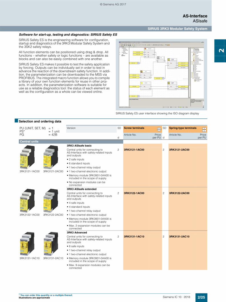
Software for start-up, testing and diagnostics: SIRIUS Safety ES
SIRIUS Safety ES is the engineering software for configuration, startup and diagnostics of the 3RK3 Modular Safety System and the 3SK2 safety relays.
All function elements can be positioned using drag & drop. All functions – whether safety or logic functions – are available as blocks and can also be easily combined with one another.
SIRIUS Safety ES makes it possible to test the safety application by forcing. Outputs can be individually set in order to test in advance the reaction of the downstream safety function. In addi-tion, the parameterization can be downloaded to the MSS via PROFIBUS. The integrated macro function allows you to compile a library of your own function elements for reuse in other proj-ects. In addition, the parameterization software is suitable for use as a reliable diagnostics tool: the status of each element as well as the configuration as a whole can be viewed online.
SIRIUS Safety ES user interface showing the ISO diagram display
■ Selection and ordering data
PU (UNIT, SET, M) = 1PS* = 1 unitPG = 42B
Version SD Screw terminals SD Spring-type terminals
dArticle No. Price
per PU dArticle No. Price
per PUCentral units
3RK3121-1AC00 3RK3121-2AC00
3RK3 ASIsafe basic
Central units for connecting to AS-Interface with safety-related inputs and outputs• 2 safe inputs• 6 standard inputs• 1 two-channel relay output• 1 two-channel electronic output• Memory module 3RK3931-0AA00 is
included in the scope of supply• No expansion modules can be
connected
2 3RK3121-1AC00 2 3RK3121-2AC00
3RK3122-1AC00 3RK3122-2AC00
3RK3 ASIsafe extended
Central units for connecting to AS-Interface with safety-related inputs and outputs• 4 safe inputs• 4 standard inputs• 1 two-channel relay output• 1 two-channel electronic output• Memory module 3RK3931-0AA00 is
included in the scope of supply• Max. 2 expansion modules can be
connected
2 3RK3122-1AC00 2 3RK3122-2AC00
3RK3131-1AC10 3RK3131-2AC10
3RK3 Advanced
Central units for connecting to AS-Interface with safety-related inputs and outputs• 8 safe inputs • 1 two-channel relay output• 1 two-channel electronic output• Memory module 3RK3931-0AA00 is
included in the scope of supply• Max. 9 expansion modules can be
connected
2 3RK3131-1AC10 2 3RK3131-2AC10
© Siemens AG 2017

2/26 Siemens IC 10 · 2018* You can order this quantity or a multiple thereof.
Illustrations are approximate
AS-InterfaceASIsafe
SIRIUS 3RK3 Modular Safety System
2 Expansion modules
3RK3211-1AA10 3RK3211-2AA10
4/8 F-DI
Safety-related input modules• 8 inputs
2 3RK3211-1AA10 2 3RK3211-2AA10
3RK3221-1AA10 3RK3221-2AA10
2/4 F-DI 1/2 F-RO
Safety-related input/output modules• 4 inputs• 2 single-channel relay outputs
2 3RK3221-1AA10 2 3RK3221-2AA10
3RK3231-1AA10 3RK3231-2AA10
2/4 F-DI 2 F-DO
Safety-related input/output modules• 4 inputs• 2 two-channel electronic outputs
2 3RK3231-1AA10 2 3RK3231-2AA10
3RK3251-1AA10 3RK3251-2AA10
4/8 F-RO
Safety-related output modules• 8 single-channel relay outputs
2 3RK3251-1AA10 2 3RK3251-2AA10
3RK3242-1AA10 3RK3242-2AA10
4 F-DO
Safety-related output modules• 4 two-channel electronic outputs
2 3RK3242-1AA10 2 3RK3242-2AA10
3RK3321-1AA10 3RK3321-2AA10
8 DI
Standard input module• 8 inputs
2 3RK3321-1AA10 2 3RK3321-2AA10
3RK3311-1AA10 3RK3311-2AA10
8 DO
Standard output module• 8 solid-state outputs
2 3RK3311-1AA10 2 3RK3311-2AA10
Interface modules
3RK3511-1BA10 3RK3511-2BA10
DP interface
PROFIBUS DP interface, 12 Mbps, RS 485, cyclic and acyclic data exchange
2 3RK3511-1BA10 2 3RK3511-2BA10
PU (UNIT, SET, M) = 1PS* = 1 unitPG = 42B
Version SD Screw terminals SD Spring-type terminals
dArticle No. Price
per PU dArticle No. Price
per PU
© Siemens AG 2017

2/27Siemens IC 10 · 2018* You can order this quantity or a multiple thereof.Illustrations are approximate
AS-InterfaceASIsafe
SIRIUS 3RK3 Modular Safety System
2
■ Accessories
✓ Available-- Not available
Additional accessories for MSS, see page 11/40.
■ More information
Version SD Article No. Priceper PU
PU(UNIT,
SET, M)
PS* PG
dConnection cables (essential accessory)
3UF7932-0AA00-0
For connection of Central units with expan-sion modules or interface module
Diagnostics modules with central unit or interface module
✓ ✓ • Length 0.025 m (flat) } 3UF7930-0AA00-0 1 1 unit 42J-- ✓ • Length 0.1 m (flat) } 3UF7931-0AA00-0 1 1 unit 42J-- ✓ • Length 0.3 m (flat) } 3UF7935-0AA00-0 1 1 unit 42J-- ✓ • Length 0.5 m (flat) } 3UF7932-0AA00-0 1 1 unit 42J-- ✓ • Length 0.5 m (round) } 3UF7932-0BA00-0 1 1 unit 42J-- ✓ • Length 1.0 m (round) } 3UF7937-0BA00-0 1 1 unit 42J-- ✓ • Length 2.5 m (round) } 3UF7933-0BA00-0 1 1 unit 42J
Operating and monitoring modules for 3RK3
3SK2611-3AA00
Diagnostics module 2 3SK2611-3AA00 1 1 unit 41LFor direct display of errors, e.g. of cross-circuits
More information
Modular safety system (MSS), see from page 11/30 onwardsSIRIUS Safety ES software, see from page 14/26 onwards
System Manual "SIRIUS 3RK3 Modular Safety System (MSS)", see https://support.industry.siemens.com/cs/ww/en/view/26493228
© Siemens AG 2017

2/28 Siemens IC 10 · 2018* You can order this quantity or a multiple thereof.
Illustrations are approximate
AS-InterfaceASIsafe
AS-Interface safety monitors
2
■ Selection and ordering data
■ Accessories
Version SD Article No. Priceper PU
PU(UNIT,
SET, M)
PS* PG
d
3RK1105-1BE04-0CA0
Basic safety monitors Version 3With screw terminals, removable terminals, width 45 mm
Screw terminals
• 1 enabling circuit (monitor type 1) 2 3RK1105-1AE04-0CA0 1 1 unit 42C• 2 enabling circuits (monitor type 2) 2 3RK1105-1BE04-0CA0 1 1 unit 42CExpanded safety monitorsVersion 3With screw terminals, removable terminals, width 45 mm• 1 enabling circuit (monitor type 3) 2 3RK1105-1AE04-2CA0 1 1 unit 42C• 2 enabling circuits (monitor type 4) 2 3RK1105-1BE04-2CA0 1 1 unit 42CExpanded safety monitor with integrated safe slaveVersion 3With screw terminals, removable terminals, width 45 mm• 2 enabling circuits including control of a safe AS-i output/
safe coupling (monitor type 6)2 3RK1105-1BE04-4CA0 1 1 unit 42C
Basic safety monitors Version 3With spring-type terminals, removable terminals, width 45 mm
Spring-type terminals
• 1 enabling circuit (monitor type 1) 2 3RK1105-1AG04-0CA0 1 1 unit 42C• 2 enabling circuits (monitor type 2) 2 3RK1105-1BG04-0CA0 1 1 unit 42CExpanded safety monitorsVersion 3With spring-type terminals, removable terminals, width 45 mm• 1 enabling circuit (monitor type 3) 2 3RK1105-1AG04-2CA0 1 1 unit 42C• 2 enabling circuits (monitor type 4) 2 3RK1105-1BG04-2CA0 1 1 unit 42CExpanded safety monitor with integrated safe slaveVersion 3With spring-type terminals, removable terminals, width 45 mm• 2 enabling circuits including control of a safe AS-i output/
safe coupling (monitor type 6)2 3RK1105-1BG04-4CA0 1 1 unit 42C
Version SD Article No. Priceper PU
PU(UNIT,
SET, M)
PS* PG
dASIsafe CD
Included in the scope of supply:2 3RK1802-2FB06-0GA1 1 1 unit 42C
• ASIMON V3 configuration software on CD ROM, for PC with the 32-bit operating systems Windows XP, Windows Vista Business/Ultimate, Windows 7
3RK1901-5AA00
Cable sets
Included in the scope of supply:} 3RK1901-5AA00 1 1 unit 42C
• PC configuration cable for communication between PC (serial interface) and safety monitor, length approx. 1.50 m
• Transfer cable between two safety monitors, length approx. 0.25 m
Sealable coversFor securing against unauthorized configuration of the safety monitor
5 3RP1902 1 5 units 41H
Push-in lugs For screw fixing
5 3RP1903 1 10 units 41H
© Siemens AG 2017

2/29Siemens IC 10 · 2018
AS-InterfaceASIsafe
AS-Interface safety modules
2
■ Overview
AS-Interface safety modules: K45F (left), K20F (center) and SC17.5F (right)
S45F SlimLine module, safe AS-i output
Safety modules for AS-Interface (ASIsafe modules) are available for field use in degree of protection IP67 (K20F and K45F com-pact modules) and for the control cabinet (SC17.5F SlimLine Compact modules) in degree of protection IP20.
A very compact module with an optimum price/performance ratio is thus available for very application.
All modules for the connection of (mechanical) switches and safety sensors with contacts feature crossover monitoring of the connected sensor line. On versions for the connection of electronic switches and safety sensors (e.g. light arrays) the cross-circuit monitoring must be performed by the sensor.
AS-Interface safety modules
The following modules are available for selection:
K20F compact safety modules for operation in the field
Being only 20 mm wide, the K20F module is particularly well suited for applications where modules need to be arranged in the most confined of spaces. The K20F modules are connected to the AS-Interface with a round cable with M12 cable box instead of with the AS-Interface flat cable. This enables extremely compact installation. The flexibility of the round cable means that it can also be used on moving machine parts without any problems. The K20 modules are also ideal for such applica-tions as their non-encapsulated design makes them particularly light in weight.
K45F compact safety modules for use in the field
The platform of the K45F modules covers the following variations:• Connection of ("mechanical") switches/safety sensors
with contacts:- K45F 2F-DI: Two safety-related inputs in operation up to
Category 2 according to EN ISO 13849-1. If Category 4 is required, a two-channel input is available on the module.
- K45F 2F-DI/2DQ: There are also two standard outputs in addition to the safe inputs. Supplied from the yellow AS-i cable
- K45F 2F-DI/2DQ Uaux: same as K45F 2F-DI/2DQ, but supplied from the black 24 V DC cable
- K45F 4F-DI: Four safety-related inputs in operation up to Category 2, two for Category 4. Extremely compact double slave (uses two full AS-i addresses).
• Connection of solid-state switches/safety sensors (non-contact protective devices, BWS):- K45F LS (light sensor): Safe input module for the connection
of electronic safety sensors with testing semiconductor outputs (OSSD) In particular non-contact protective devices such as active, optoelectronic light arrays and light curtains for Type 2 and Type 4 according to IEC 61496.Transmitters as well as receivers are supplied with power from the yellow AS-i cable. Matching sensor cables and optionally a separate transmitter supply module are available as accessories.
SC17.5F SlimLine Compact safety modules with a width of just 17.5 mm for use in control cabinets and local control boxes
With a width of only 17.5 mm, the safe SlimLine Compact modules SC17.5F are ideal for space-saving use in a control cabinet. The modules have more than two safety inputs for connecting signals to ASIsafe networks in the control cabinet. For operation up to Category 2, both inputs can be separately assigned; if Category 4 is required, a two-channel input is available on the module.
There are also two module variants which have two standard outputs in addition to the two safety inputs. The outputs are supplied either from the yellow AS-Interface cable alone, or via auxiliary voltage from the black 24 V DC cable. The supply voltage is set via a slide switch on the rear of the device.
When using several modules, they can be connected simply via the optional device connector. This simplifies the wiring. The yellow AS-i bus cable and the 24 V DC auxiliary voltage Uaux then only need to be connected to one module.
© Siemens AG 2017

2/30 Siemens IC 10 · 2018* You can order this quantity or a multiple thereof.
Illustrations are approximate
AS-InterfaceASIsafe
AS-Interface safety modules
2
S45F SlimLine safety modules with safety outputs for the safedistributed disconnection of actuators
With the S45F SlimLine safety module, the shutdown signal, for example from the Modular Safety System, can be used via ASIsafe for distributed safety-related disconnection.
To this end, the module has a two-channel relay output. As an additional possibility the module offers normal switching of the output using an AS-i standard output bit.
The module has three digital inputs and two digital outputs for the additional connection of sensors and actuators. These can be used, among other things, for the required monitoring of downstream contactors of the feedback circuit.
■ Selection and ordering data
✓ Available or possible-- Not available or not possible1) Module occupies two AS-Interface addresses2) Connection of previous Siemens light curtain FS 400 3RG7843 (type 2)
through socket 1/3.3) Connection of previous Siemens light curtain FS 400 3RG7846 (type 4)
through socket 1/3, other makes through socket 2/3.
The existing SlimLine series of I/O modules for use in the control cabinet and local control boxes is being replaced by the new SlimLine Compact series. We recommend that these new devices are used in future.
For the conversion table, see page 2/73.
Note:
The previous SlimLine devices are still available for use as replacements in existing systems. As a result of the innovation, the new SlimLine Compact devices are not fully compatible in terms of either mechanical dimensions or electrical properties.
Version SD Article No. Priceper PU
PU(UNIT,
SET, M)
PS* PG
d
3RK1205-0BQ30-0AA3
K20F compact safety modules
I/O type Uaux 24 V2F-DI -- 2 3RK1205-0BQ30-0AA3 1 1 unit 42C
3RK1205-0BQ00-0AA3
K45F compact safety modules
Modules supplied without mounting plateI/O type Uaux 24 V2F-DI -- } 3RK1205-0BQ00-0AA3 1 1 unit 42C4F-DI1) -- 2 3RK1205-0CQ00-0AA3 1 1 unit 42C2F-DI/2DQ -- 5 3RK1405-0BQ20-0AA3 1 1 unit 42C2F-DI/2DQ 5 3RK1405-1BQ20-0AA3 1 1 unit 42C2F-DI LS type 22) -- 5 3RK1205-0BQ21-0AA3 1 1 unit 42C2F-DI LS type 43) -- 5 3RK1205-0BQ24-0AA3 1 1 unit 42C
3RK1405-0BE00-2AA2
SC17.5F SlimLine Compact safety modules
(Slave type: Standard)Connection I/O type OutputsScrew 2F-DI -- 2 3RK1205-0BE00-2AA2 1 1 unit 42C
Spring-type(push-in)
2 3RK1205-0BG00-2AA2 1 1 unit 42C
Screw 2F-DI/2Q UASI/Uaux supplyselectable
2 3RK1405-2BE00-2AA2 1 1 unit 42C
Spring-type(push-in)
2 3RK1405-2BG00-2AA2 1 1 unit 42C
3RK1405-1SE15-0AA2
S45F SlimLine safety module
(with safe AS-i output) Connection I/O type Uaux 24 VScrew 1F-RQ/3DI/2DQ 2 3RK1405-1SE15-0AA2 1 1 unit 42C
Spring-type 2 3RK1405-1SG15-0AA2 1 1 unit 42C
© Siemens AG 2017

2/31Siemens IC 10 · 2018* You can order this quantity or a multiple thereof.Illustrations are approximate
AS-InterfaceASIsafe
AS-Interface safety modules
2
■ Accessories
1) PC labeling system for individual inscription of unit labeling plates available from: murrplastik Systemtechnik GmbH (see page 16/15).
■ More information
Version SD Article No. Priceper PU
PU(UNIT,
SET, M)
PS* PG
d
Accessories for compact safety modules
3RK1901-2EA00
K45 mounting platesFor mounting K45F• For wall mounting } 3RK1901-2EA00 1 1 unit 42C• For standard rail mounting } 3RK1901-2DA00 1 1 unit 42C24 V supply modules for K45F LS (light sensor) 5 3RK1901-1NP00 1 1 unit 42C• Optional, for transmitter power supply for large protective field
widths• Max. current carrying capacity 200 mA• Modules supplied without mounting plate
3RK1901-1AA00
Input bridges for K45F
• Black version 2 3RK1901-1AA00 1 1 unit 42C• Red version 30 3RK1901-1AA01 1 1 unit 42C
3RK1901-1KA00
AS-Interface sealing caps M12For free M12 sockets
} 3RK1901-1KA00 100 10 units 42C
3RK1901-1KA01
AS-Interface M12 sealing caps, tamper-proofFor free M12 sockets
2 3RK1901-1KA01 100 10 units 42C
Accessories for SlimLine Compact safety modules
3RK1901-1YA00
3RK1901-1YA01
Device connectors
For the electrical connection of SlimLine Compact modules (connects AS-i bus cable and 24 V DC auxiliary power supply Uaux when using several SlimLine Compact modules)• Width 17.5 mm 2 3RK1901-1YA00 1 1 unit 42C• Width 22.5 mm 2 3RK1901-1YA10 1 1 unit 42CDevice termination connectors
Required for the last module in the network• Width 17.5 mm 2 3RK1901-1YA01 1 1 unit 42C• Width 22.5 mm 2 3RK1901-1YA11 1 1 unit 42C
3ZY1121-2BA00
Removable terminals Screw terminals
• Screw terminals up to 2 x 1.5 mm2 or 1 x 2.5 mm2
- 2-pole 2 3ZY1121-1BA00 1 6 units 41L- 4-pole 2 3ZY1141-1BA00 1 6 units 41L
Spring-type terminals (push-in)
• Push-In terminals up to 2 x 1.5 mm2
- 2-pole 2 3ZY1121-2BA00 1 6 units 41L- 4-pole 2 3ZY1141-2BA00 1 6 units 41L
Push-in lugs for wall mounting
Two lugs are required per device2 3ZY1311-0AA00 1 10 units 41L
Coding pins for removable terminals
For mechanical coding of the terminals2 3ZY1440-1AA00 1 12 units 41L
3RT2900-1SB20
Blank labels
Unit labeling plates1)
• 10 mm x 7 mm, titanium gray 20 3RT2900-1SB10 100 816 units 41B• 20 mm x 7 mm, titanium gray 20 3RT2900-1SB20 100 340 units 41B
3RA2908-1A
Tools for opening spring-type terminals Spring-type terminals (push-in)
Screwdriver for SIRIUS devices with spring-type terminals3.0 mm x 0.5 mm, length approx. 200 mm, titanium gray/black, partially insulated
2 3RA2908-1A 1 1 unit 41B
IC01
_001
81
More information
For the Manual "AS-Interface SlimLine Compact Modules", see https://support.industry.siemens.com/cs/ww/en/view/109481489
© Siemens AG 2017
2/32 Siemens IC 10 · 2018
AS-InterfaceMastersMasters for SIMATIC S7
CM 1243-2
2
■ Overview
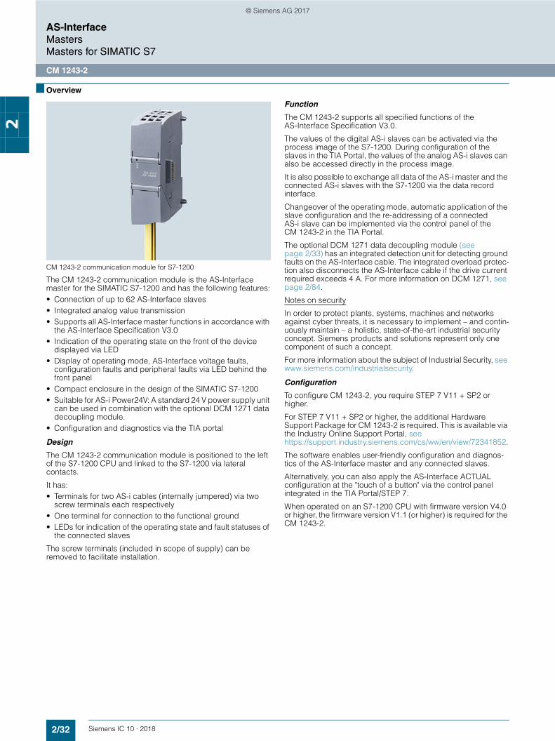
CM 1243-2 communication module for S7-1200
The CM 1243-2 communication module is the AS-Interface master for the SIMATIC S7-1200 and has the following features:• Connection of up to 62 AS-Interface slaves• Integrated analog value transmission• Supports all AS-Interface master functions in accordance with
the AS-Interface Specification V3.0• Indication of the operating state on the front of the device
displayed via LED• Display of operating mode, AS-Interface voltage faults,
configuration faults and peripheral faults via LED behind the front panel
• Compact enclosure in the design of the SIMATIC S7-1200• Suitable for AS-i Power24V: A standard 24 V power supply unit
can be used in combination with the optional DCM 1271 data decoupling module.
• Configuration and diagnostics via the TIA portal
Design
The CM 1243-2 communication module is positioned to the left of the S7-1200 CPU and linked to the S7-1200 via lateral contacts.
It has:• Terminals for two AS-i cables (internally jumpered) via two
screw terminals each respectively• One terminal for connection to the functional ground• LEDs for indication of the operating state and fault statuses of
the connected slaves
The screw terminals (included in scope of supply) can be removed to facilitate installation.
Function
The CM 1243-2 supports all specified functions of the AS-Interface Specification V3.0.
The values of the digital AS-i slaves can be activated via the process image of the S7-1200. During configuration of the slaves in the TIA Portal, the values of the analog AS-i slaves can also be accessed directly in the process image.
It is also possible to exchange all data of the AS-i master and the connected AS-i slaves with the S7-1200 via the data record interface.
Changeover of the operating mode, automatic application of the slave configuration and the re-addressing of a connected AS-i slave can be implemented via the control panel of the CM 1243-2 in the TIA Portal.
The optional DCM 1271 data decoupling module (see page 2/33) has an integrated detection unit for detecting ground faults on the AS-Interface cable. The integrated overload protec-tion also disconnects the AS-Interface cable if the drive current required exceeds 4 A. For more information on DCM 1271, see page 2/84.
Notes on security
In order to protect plants, systems, machines and networks against cyber threats, it is necessary to implement – and contin-uously maintain – a holistic, state-of-the-art industrial security concept. Siemens products and solutions represent only one component of such a concept.
For more information about the subject of Industrial Security, see www.siemens.com/industrialsecurity.
Configuration
To configure CM 1243-2, you require STEP 7 V11 + SP2 or higher.
For STEP 7 V11 + SP2 or higher, the additional Hardware Support Package for CM 1243-2 is required. This is available via the Industry Online Support Portal, see https://support.industry.siemens.com/cs/ww/en/view/72341852.
The software enables user-friendly configuration and diagnos-tics of the AS-Interface master and any connected slaves.
Alternatively, you can also apply the AS-Interface ACTUAL configuration at the "touch of a button" via the control panel integrated in the TIA Portal/STEP 7.
When operated on an S7-1200 CPU with firmware version V4.0 or higher, the firmware version V1.1 (or higher) is required for the CM 1243-2.
© Siemens AG 2017

2/33Siemens IC 10 · 2018* You can order this quantity or a multiple thereof.Illustrations are approximate
AS-InterfaceMasters
Masters for SIMATIC S7
CM 1243-2
2
■ Benefits
• More flexibility and versatility in the use of SIMATIC S7-1200 as the result of a significant increase in the number of digital and analog inputs/outputs available
• Very easy configuration and diagnostics of the AS-Interface via the TIA Portal (STEP 7 V11+SP2 or higher)
• No need for the AS-i power supply unit with AS-i Power24V: the AS-Interface cable is supplied through an existing 24 V DC PELV power supply unit. For decoupling, the AS-i DCM 1271 data decoupling module is required, see "Accessories" and page 2/84.
• LEDs for indication of fault statuses for fast diagnostics• Monitoring of AS-Interface voltage facilitates diagnostics
■ Application
The CM 1243-2 is the AS-Interface master connection for the 12xx CPUs of the SIMATIC S7-1200. Through connection to AS-Interface, the number of digital inputs and outputs available for the S7-1200 is greatly increased (max. 496 DI/496 DQ on the AS-Interface per CM).
The integrated analog value processing also makes the analog values available at the AS-Interface for the S7-1200 (per CM up to 31 standard analog slaves, each with up to four channels, or up to 62 A/B analog slaves, each with up to two channels).
Operating conditions• The CM 1243-2 communication module exchanges data with
the S7-1200 CPU with a cycle time of 10 ms.• The AS-i cycle time depends on the AS-i bus capacity and is
up to 5 ms in the case of 31 standard slaves; for more information, see Manual "AS-i Master CM 1243-2 and AS-i Data Decoupling Unit DCM 1271 for SIMATIC S7-1200", https://support.industry.siemens.com/cs/ww/en/view/57358958.
• For calculation of the maximum switching frequency at inputs/outputs of AS-i slaves, these cycle times and the runtime of the user program must be added up.
■ Selection and ordering data
■ Accessories
■ More information
Version SD Screw terminals PU(UNIT,
SET, M)
PS* PG
dArticle No. Price
per PU
3RK7243-2AA30-0XB0
CM 1243-2 communication module 2 3RK7243-2AA30-0XB0 1 1 unit 42C• AS-Interface masters for SIMATIC S7-1200• Corresponds to AS-Interface Specification V3.0• With screw terminals, removable terminals
(included in the scope of supply)• Dimensions (W H D/mm): 30 100 75
Version SD Screw terminals PU(UNIT,
SET, M)
PS* PG
dArticle No. Price
per PU
3RK7271-1AA30-0AA0
DCM 1271 data decoupling module
• With screw terminals, removable terminals (included in the scope of supply)
• Dimensions (W H D/mm): 30 100 75
2 3RK7271-1AA30-0AA0 1 1 unit 42C
Screw terminals (replacement)
• 5-pin For AS-i master CM 1243-2 and AS-i DCM 1271 data decoupling module
5 3RK1901-3MA00 1 1 unit 42C
• 3-pin For AS-i DCM 1271 data decoupling module for connecting the power supply unit
5 3RK1901-3MB00 1 1 unit 42C
More information
Manuals, see https://support.industry.siemens.com/cs/ww/en/ps/15750/manFor diagnostics during ongoing operation, diagnostics blocks with clearly arranged visualization on the SIMATIC HMI panel are available or can be downloaded free of charge via a web browser, see https://support.industry.siemens.com/cs/ww/en/view/109479103.
© Siemens AG 2017

2/34 Siemens IC 10 · 2018
AS-InterfaceMastersMasters for SIMATIC S7
CP 343-2P / CP 343-2
2
■ Overview
CP 343-2P/CP 343-2
The CP 343-2P communications processor is the AS-Interface master for the SIMATIC S7-300 and the ET 200M distributed I/O station, with user-friendly parameterizing options.
The CP 343-2 is the basic version of the module.
The CP 343-2P/CP 343-2 has the following characteristics:• Connection of up to 62 AS-Interface slaves • Integrated analog value transmission• Support of all AS-Interface master functions in accordance
with the AS-Interface Specification V3.0• Status displays of operating states and indication of the
readiness for operation of connected slaves by means of LEDs in the front panel
• Fault indications (including AS-Interface voltage errors, configuration errors) by means of LEDs on the front plate.
• Compact enclosure in the design of the SIMATIC S7-300• Suitable for AS-i Power24V (from product version 2/firmware
version 3.1) and for standard AS-i with 30 V voltage• Additionally for CP 343-2P: Supports the configuration of the
AS-Interface network with STEP 7 V5.2 and higher
Design
The CP 343-2P/CP 343-2 is connected like an I/O module to the S7-300. It has:• Two terminal connections for connecting the AS-Interface
cable directly.• LEDs in the front panel for indicating the operating state and
the readiness for operation of all connected and activated slaves
• Pushbuttons for switching over the master operating state and for adopting the existing ACTUAL configuration of the AS-i slave as the TARGET configuration
Function
The CP 343-2P/CP 343-2 supports all specified functions of the AS-Interface Specification V3.0.
The CP 343-2P/CP 343-2 each occupy 16 bytes in the I/O address area of the SIMATIC S7-300. The digital I/O data of the standard slaves and A slaves is saved in this area. The digital I/O data of the B slaves and the analog I/O data can be accessed with the S7 system functions for read/write data records.
If required, master calls can be performed with the command interface, e.g. read/write parameters, read/write configuration.
For more information, see https://support.industry.siemens.com/cs/ww/en/view/51678777.
Notes on security
In order to protect plants, systems, machines and networks against cyber threats, it is necessary to implement – and continuously maintain – a holistic, state-of-the-art industrial security concept. Siemens products and solutions represent only one component of such a concept.
For more information about the subject of Industrial Security, see www.siemens.com/industrialsecurity.
Configuration
All connected AS-Interface slaves are configured at the press of a button. No further configuration of the CP is required.
Additionally for CP 343-2P
The CP 343-2P also supports configuring of the AS-Interface network with STEP 7 V5.2 and higher. Specifying the AS-i config-uration in HW-Config facilitates the setting of slave parameters and documentation of the plant. Uploading the ACTUAL config-uration of an already configured AS-Interface network is also supported. The saved configuration cannot be overwritten at the press of a button and is therefore tamper-proof.
■ Benefits
• Shorter start-up times through simple configuration at the press of a button
• Design of flexible machine-related structures using the ET 200M distributed I/O system
• Provides diagnostics of the AS-Interface network• Well suited also for complex applications thanks to connection
options for 62 slaves and integral analog value processing• Reduction of standstill and servicing times in the event of a
fault thanks to the LED indicators: - Status of the AS-Interface network- Slaves connected and their readiness for operation- Monitoring of the AS-Interface voltage
• Lower costs for stock keeping and spare parts inventory because the CP can be used for the SIMATIC S7-300 and also for the ET 200M
• Additionally for CP 343-2P: Improved plant documentation and support for service assignments thanks to a description of the AS-Interface configuration in the STEP 7 project
• No need for the AS-i power supply unit with AS-i Power24V: The AS-Interface cable is supplied through an existing 24 V DC PELV power supply unit. An S22.5 AS-i data decoupling module (e.g. 3RK1901-1DE12-1AA0) is required for decoupling, see page 2/85.
• Operation with IP20 AS-Interface power supply (see page 2/79) also possible without restrictions
© Siemens AG 2017

2/35Siemens IC 10 · 2018* You can order this quantity or a multiple thereof.Illustrations are approximate
AS-InterfaceMasters
Masters for SIMATIC S7
CP 343-2P / CP 343-2
2
■ Application
The CP 343-2P/CP 343-2 is the AS-Interface master connection for the SIMATIC S7-300 and the ET 200M.
Through connection to AS-Interface it is possible to access max. 248 DI/248 DQ per CP, using 62 A/B slaves with 4 DI/4 DQ each.
With the integrated analog value processing, it is easy to transmit analog signals (per CP up to 62 A/B analog slaves with a maximum of 2 channels each or up to 31 standard analog slaves with a maximum of 4 channels each).
The CP 343-2P is the further development of the CP 343-2 and contains its entire functionality. An existing STEP 7 user program for a CP 343-2 can thus be used without restrictions with a CP 343-2P. It is only in STEP 7 HW-Config that the two modules are configured differently, with the CP 343-2P offering additional options. This is why the CP 343-2P is recommended.
■ Selection and ordering data
■ Accessories
■ More information
Version SD Article No. Priceper PU
PU(UNIT,
SET, M)
PS* PG
d
6GK7343-2AH11-0XA0
CP 343-2P communications processors } 6GK7343-2AH11-0XA0 1 1 unit 42C• For connection of SIMATIC S7-300 and ET 200M to
AS-Interface• Configuration of the AS-i network using the SET key or
STEP 7 (V5.2 and higher)• Without front connector• Corresponds to AS-Interface Specification V3.0• Dimensions (W x H x D/mm): 40 x 125 x 120
6GK7343-2AH01-0XA0
CP 343-2 communications processors } 6GK7343-2AH01-0XA0 1 1 unit 42C• Basic version for connection of SIMATIC S7-300 and
ET 200M to AS-Interface• Configuration of the AS-i network using the SET key• Without front connector• Corresponds to AS-Interface Specification V3.0• Dimensions (W x H x D/mm): 40 x 125 x 120
Version SD Article No. Priceper PU
PU(UNIT,
SET, M)
PS* PG
dFront connector, 20-pole
• With screw terminals 1 6ES7392-1AJ00-0AA0 1 1 unit 230
• With spring-type terminals 1 6ES7392-1BJ00-0AA0 1 1 unit 230
More information
For manuals, see https://support.industry.siemens.com/cs/ww/en/ps/15754/man
For diagnostics during ongoing operation, diagnostics blocks with clearly arranged visualization on the SIMATIC HMI panel are available or can be downloaded free of charge via a web browser, see https://support.industry.siemens.com/cs/ww/en/view/61892138.AS-i block library for SIMATIC PCS 7 for easy connection of AS-Interface to PCS 7, see from page 14/23 onwards.
© Siemens AG 2017

2/36 Siemens IC 10 · 2018
AS-InterfaceMastersMasters for SIMATIC ET 200
CM AS-i Master ST for SIMATIC ET 200SP
2
■ Overview
CM AS-i Master ST for SIMATIC ET 200SP
The CM AS-i Master ST communication module is designed for use in the SIMATIC ET 200SP distributed I/O system and has the following features:• Connection of up to 62 AS-Interface slaves• Supports all AS-Interface master functions according to the
AS-Interface Specification V3.0• User-friendly configuration with graphic display of the AS-i line
in TIA Portal V12 or higher, or via GSD in other systems• Supply via AS-Interface cable• Suitable for AS-i Power24V and for AS-Interface with 30 V
voltage• Integrated ground-fault monitoring for the AS-Interface cable• Through connection to AS-Interface, the number of digital
inputs and outputs available for the control system is greatly increased (max. 496 DI/496 DQ on the AS-Interface per CM AS-i Master ST).
• Integrated analog value processing
ET 200SP distributed I/O system
The SIMATIC ET 200SP is a scalable and highly flexible distributed I/O system for connecting the process signals to a central control system via PROFIBUS or PROFINET.
Up to eight CM AS-i Master STs can be plugged into a SIMATIC ET 200SP with the IM 155-6 PN standard interface module.
For more information, see "SIMATIC ET 200SP Distributed I/O system", https://support.industry.siemens.com/cs/ww/en/view/58649293.
DesignThe CM AS-i Master ST module has an ET 200SP module enclosure with a width of 20 mm. A C0 type BaseUnit (BU) is required for use in the ET 200SP. The communication module has LED indicators for diagnostics, operation, AS-i voltage and AS-i slave status and offers informative front-side module inscription for• Plain-text marking of the module type and function class• 2D matrix code (Article No. and serial number)• Circuit diagram• Color coding of the CM module type: Light gray• Hardware and firmware version• Complete article number
FunctionThe CM AS-i Master ST communication module supports all specified functions of the AS-Interface Specification V3.0.The input/output values of the digital AS-i slaves can be activated via the cyclic process image. The values of the analog AS-i slaves are accessible via the cyclic process image (firmware V1.1 or higher) or via data record transfer.If required, master calls can be performed with the command interface, e.g. read/write parameters, read/write configuration.Changeover of the operating mode, automatic application of the slave configuration and the re-addressing of a connected AS-i slave can be implemented via the control panel of the CM AS-i Master ST in STEP 7.
Expansions as from firmware version V1.1
For the implementation of modular machine concepts, the AS-i Slaves can be activated or deactivated via the PLC program (option handling). The configuration of AS-i slaves can be modified while being executed, thus enabling variable machine setups and tool changing with integrated input/output modules during ongoing operation. AS-i input/output modules can be added to the system without deactivating the controller.
An existing AS-i installation can be read into the STEP 7 hardware configuration and adapted and documented in the project. Analog values are transmitted via the cyclic process image, the length of which is adjustable and extendable up to 288 bytes (depending on the interface module (IM) used).
Diagnostic information is accessed via automatic alarm indica-tions, via the process image or data record reading in the user program or in the STEP 7 engineering system in a graphical overview matrix. The transmission quality of the AS-i network can also be read out. To avoid configuration errors, duplicate addresses can be detected on the AS-i network.
The new functions are available with TIA Portal STEP 7 V13 SP1 or with STEP 7 V5.5 with HSP 2092 V3.01). Configuration is possible with SIMATIC CPUs S7-300 up to S7-1500 and with a SINUMERIK 840D sl or other controller.
In the network view, the AS-i slaves' online diagnostics status can be displayed directly on the slaves (for S7-1500 CPUs with firmware version V2.0 or higher, with TIA Portal STEP 7 V14 or higher).
Notes on security
In order to protect plants, systems, machines and networks against cyber threats, it is necessary to implement – and contin-uously maintain – a holistic, state-of-the-art industrial security concept. Siemens products and solutions represent only one component of such a concept.
For more information about the subject of Industrial Security, see www.siemens.com/industrialsecurity.
1) For HSP 2092, see https://support.industry.siemens.com/cs/ww/en/view/23183356.
© Siemens AG 2017

2/37Siemens IC 10 · 2018
AS-InterfaceMasters
Masters for SIMATIC ET 200
CM AS-i Master ST for SIMATIC ET 200SP
2
Configuration
The following software is required for configuration of the CM AS-i Master ST module:• STEP 7 (classic) V5.5 SP3 HF4 or higher with HSP 2092 or
HSP 2092 V3.0 (for firmware V1.1) or• STEP 7 (TIA Portal) V12 or higher or V13 SP1 or higher
(for firmware V1.1) or• the GSD file of the ET 200SP with STEP 7 or another
engineering toolSTEP 7 enables user-friendly configuration and diagnostics of the AS-i master and any connected slaves.
Alternatively, you can also apply the AS-Interface ACTUAL configuration as the DESIRED configuration at the "touch of a button" via the control panel integrated in the TIA Portal or an optional expansion button. Configuration with the GSD file is possible only with the button.
The CM AS-i Master ST module occupies up to 288 input bytes and up to 288 output bytes in the I/O data of the ET 200SP station. The I/O assignment depends on the configuration in STEP 7.
Together with an ET 200SP CPU 1510SP/1512SP (firmware V1.8 or higher) or 1515SP PC, preprocessing of safe AS-i signals di-rectly in the ET 200SP station and setting up of an independent AS-i Safety station without a higher-level CPU are possible (TIA Portal V13 SP1 Update 4 and higher).
Configuration of an AS-Interface network with CM AS-i Master ST via the TIA Portal
■ Benefits
The CM AS-i Master ST for ET 200SP communication module enables modular, simple and high-performance expansion of AS-interface networks via engineering in the TIA Portal.
Up to eight CM AS-i Master ST units can be plugged into one ET 200SP station with IM 155-6 PN Standard. The maximum configuration depends on the interface module used.
Multiple masters as well as single masters can thus be imple-mented in the ET 200SP depending on the number of modules.
Together with the interface module, a scalable PROFINET/AS-i Link or PROFIBUS/AS-i Link can be assembled.
Using STEP 7, the AS-i network is consistently configured and programmed with only one configuration tool.
The PRONETA PC program (for ET 200SP with PROFINET interface module) is available for convenient input/output testing during the commissioning of an AS-i network without a CPU, see www.siemens.com/proneta.
For diagnostics during ongoing operation, diagnostics blocks with clearly arranged visualization on the SIMATIC HMI panel are available or can be downloaded free of charge via a web browser, see https://support.industry.siemens.com/cs/ww/en/view/109479103.
CM AS-i Master ST diagnostics block
© Siemens AG 2017

2/38 Siemens IC 10 · 2018* You can order this quantity or a multiple thereof.
Illustrations are approximate
AS-InterfaceMastersMasters for SIMATIC ET 200
CM AS-i Master ST for SIMATIC ET 200SP
2
■ Application
Configuration examples of AS-Interface networks with CM AS-i Master ST for SIMATIC ET 200SP
Configuration of AS-Interface networks under a SIMATIC ET 200SP
■ Selection and ordering data
Version SD Article No. Priceper PU
PU(UNIT,
SET, M)
PS* PG
d
3RK7137-6SA00-0BC1
CM AS-i Master ST communication module 2 3RK7137-6SA00-0BC1 1 1 unit 42C
• AS-Interface master for SIMATIC ET 200SP, can be plugged onto BaseUnit type C0
• Corresponds to AS-Interface Specification V3.0• Dimensions (W H D/mm): 20 x 73 x 58
1 2 3 4 5 1 2 3 4 5
Controllere.g. SIMATIC S7-1500or SIMATIC S7-300or SINUMERIK 840D sl
SIMATIC ET 200SPwith 2 x CM AS-i Masters ST
SIMATIC ET 200SPwith CM AS-i Master ST
Pushbuttons and indicator lights
Field module
3RA2 load feeder
M200D motor starter
Signal columns
1
2
4
5
3
AS-Interfacepower supply
AS-Interfacepower supply
AS-Interfacepower supply
IC01
_002
37d
PROFINET
AS-InterfaceAS-InterfaceAS-Interface
PROFIBUS
© Siemens AG 2017
2/39Siemens IC 10 · 2018* You can order this quantity or a multiple thereof.Illustrations are approximate
AS-InterfaceMasters
Masters for SIMATIC ET 200
CM AS-i Master ST for SIMATIC ET 200SP
2
■ Accessories
■ More information
Version SD Spring-type terminals PU(UNIT,
SET, M)
PS* PG
dArticle No. Price
per PU
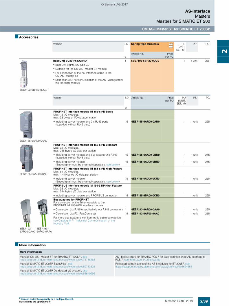
6ES7193-6BP20-0DC0
BaseUnit BU20-P6+A2+4D
• BaseUnit (light), BU type C0• Suitable for the CM AS-i Master ST module • For connection of the AS-Interface cable to the
CM AS-i Master ST• Start of an AS-i network, isolation of the AS-i voltage from
the left-hand module
1 6ES7193-6BP20-0DC0 1 1 unit 255
Version SD Article No. Priceper PU
PU(UNIT,
SET, M)
PS* PG
d
6ES7155-6AR00-0AN0
PROFINET Interface module IM 155-6 PN BasicMax. 12 I/O modules,max. 32 bytes of I/O data per station• Including server module and 2 x RJ45 ports
(supplied without RJ45 plug)15 6ES7155-6AR00-0AN0 1 1 unit 255
6ES7155-6AA00-0BN0
PROFINET Interface module IM 155-6 PN Standard Max. 32 I/O modules, max. 256 bytes I/O data per station• Including server module and bus adapter 2 x RJ45
(supplied without RJ45 plug)15 6ES7155-6AA00-0BN0 1 1 unit 255
• Including server module (BusAdapter must be ordered separately, see below)
15 6ES7155-6AU00-0BN0 1 1 unit 255
PROFINET Interface module IM 155-6 PN High FeatureMax. 64 I/O modules, max. 1 440 bytes I/O data per station• Including server module
(BusAdapter must be ordered separately, see below) 15 6ES7155-6AU00-0CN0 1 1 unit 255
PROFIBUS interface module IM 155-6 DP High Feature Max. 32 I/O modules, max. 244 bytes I/O data per station• Including server module and PROFIBUS connector 15 6ES7155-6BA00-0CN0 1 1 unit 255
6ES7193-6AR00-0AA0
6ES7193-6AF00-0AA0
Bus adapters for PROFINET For connection of the Ethernet cable to the PROFINET IM 155-6 PN interface module• Connection 2 x RJ45 (supplied without RJ45 connector) 1 6ES7193-6AR00-0AA0 1 1 unit 255• Connection 2 x FC (FastConnect) 15 6ES7193-6AF00-0AA0 1 1 unit 255For more bus adapters with fiber optic cable connection, see Catalog IK PI "Industrial Communication" or the Industry Mall.
More information
Manual "CM AS-i Master ST for SIMATIC ET 200SP", see https://support.industry.siemens.com/cs/ww/en/view/71756485Manual "SIMATIC ET 200SP BaseUnits", see https://support.industry.siemens.com/cs/ww/en/view/59753521Manual "SIMATIC ET 200SP Distributed I/O system", see https://support.industry.siemens.com/cs/ww/en/view/58649293
AS-i block library for SIMATIC PCS 7 for easy connection of AS-Interface to PCS 7, see from page 14/23 onwardsReleased combinations of the AS-i modules for ET 200SP, see https://support.industry.siemens.com/cs/ww/en/view/103624653
© Siemens AG 2017

2/40 Siemens IC 10 · 2018
AS-InterfaceMastersMasters for SIMATIC ET 200
F-CM AS-i Safety ST for SIMATIC ET 200SP
2
■ Overview
F-CM AS-i Safety ST for SIMATIC ET 200SP
The F-CM AS-i Safety ST fail-safe communication module supplements an AS-Interface network without additional wiring to produce a safety-related AS-i network.
Important features:• Fail-safe communication module for the ET 200SP
- 31 fail-safe input channels in the process image- 16 fail-safe output channels in the process image- Certified up to SIL 3 (IEC 61508/EN 62061),
PL e (EN ISO 13849-1) - Parameterization conforms with other fail-safe I/O modules
of the ET 200SP• The communication module supports PROFIsafe in
PROFINET and PROFIBUS configurations. Can be used with fail-safe SIMATIC S7-300F/S7-416F CPUs and S7-1500F CPUs and also the fail-safe versions of the ET 200SP station with ET 200SP F-CPU 1510SP F/1512SP F (firmware V1.8 or higher) or 1515SP PC F.
• For reading up to 31 fail-safe AS-i input slaves- Two sensor inputs/signals for each fail-safe AS-i input slave - Adjustable evaluation of sensor signals: 2-channel or
2 x 1-channel- Integrated discrepancy evaluation in the case of 2-channel
signals- Integrated AND operation in the case of 2 x 1-channel
signals- Input delay can be parameterized- Start-up test can be set- Sequence monitoring can be activated
• For control of up to 16 fail-safe AS-i output circuit groups- The output circuit groups are controlled independently of
one another. - One output circuit group can act on one or more actuators
(e.g. to switch drives simultaneously).- An actuator (e.g. a contactor) is interfaced via a fail-safe AS-i
output module (e.g. safe SlimLine module S45F, Article No. 3RK1405-1SE15-0AA2, see page 2/30).
- Simple fault acknowledgment via the process image• Simple module replacement thanks to automatic importing of
the safety parameters from the coding element• Comprehensive diagnostic options• Can be plugged onto type C1 or type C0 BaseUnits (BU)• Informative automatic alarm indications (firmware V1.0.1 or
higher)
• Supply via AS-Interface voltage• Eight LED indicators for diagnostics, operating state, fault
indication and supply voltage• Informative front-side module inscription
- Plain-text marking of the module type and function class- 2D matrix code (Article No. and serial number)- Circuit diagram- Color coding of the CM module type: Light gray- Hardware and firmware version- Complete article number
• Optional labeling accessories- Labeling strips- Reference identification label
Design
The fail-safe F-CM AS-i Safety ST module has an ET 200SP module enclosure with a width of 20 mm.
One AS-i master according to the AS-i Specification V3.0 and safe AS-i input slaves and/or safe AS-i output modules are needed for operation. The CM AS-i Master ST communication module (Article No. 3RK7137-6SA00-0BC1) is recommended as the AS-i master for the ET 200SP, see from page 2/36 onwards.
Simple combination of the CM AS-i Master ST and F-CM AS-i Safety ST modules in one ET 200SP station results in a powerful, safety-oriented network transition between PROFINET (or PROFIBUS) and AS-Interface, which can be expanded further in a modular fashion.
Combination of an ET 200SP interface module, CM AS-i Master ST and F-CM AS-i Safety ST
With the digital and analog I/O modules of the ET 200SP, additional local inputs and outputs can be realized so as to ensure that the modular AS-i router complies precisely with customer requirements. Expansion variants for almost every application are possible thanks to the selection of standard and fail-safe I/O modules.
Besides the single AS-i master, double, triple or generally multiple masters can be realized with or without fail-safe functionality.
Supported BaseUnits
With the combination of the CM AS-i Master ST and F-CM AS-i Safety ST modules, the CM module is plugged onto a light type C0 BaseUnit and, immediately to the right of it, the F-CM module is plugged onto a dark type C1 BaseUnit. The AS-i cable is connected only on the light BaseUnit of the CM module.
© Siemens AG 2017
2/41Siemens IC 10 · 2018
AS-InterfaceMasters
Masters for SIMATIC ET 200
F-CM AS-i Safety ST for SIMATIC ET 200SP
2
Notes on security
In order to protect plants, systems, machines and networks against cyber threats, it is necessary to implement – and contin-uously maintain – a holistic, state-of-the-art industrial security concept. Siemens products and solutions represent only one component of such a concept.
For more information about the subject of Industrial Security, see www.siemens.com/industrialsecurity.
Configuration
The following software is required for configuration of the F-CM AS-i Safety ST module:• STEP 7 (classic), V5.5 SP3 HF4 or higher with HSP 20931) and
Distributed Safety V5.4 SP5 or F-Configuration Pack SP11
or• STEP 7 (TIA Portal) V13 and higher with HSP 00702) and
Safety Advanced V13. STEP 7 V13 SP1 is required for connection to the S7-1500F. When configuring with STEP 7 V13 SP1, the latest version of HSP 0070 V2.0 (or higher) is an essential prerequisite.STEP 7 Safety V13 SP1 Update 4 and the new version of HSP 0070 V3.0 (or higher) are needed for configuration of the F-CM AS-i Safety ST module in an ET 200SP station with ET 200SP F-CPU (firmware V1.8 or higher).
Configuration and programming are done entirely in the STEP 7 user interface. No additional configuration software is needed for commissioning.
Data management – together with all other configuration data of the SIMATIC – is realized completely in the S7 project.
The input and output channels are assigned to the process image automatically and manual linking via configuration function blocks is not necessary.
If the F-CM AS-i Safety ST module is replaced, all necessary settings are automatically imported into the new module.
The F-CM AS-i Safety ST module occupies 16 input bytes and 8 output bytes in the I/O data of the ET 200SP station.
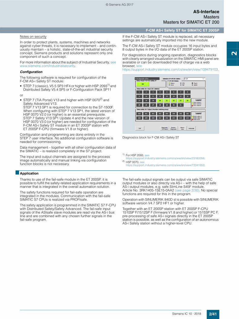
For diagnostics during ongoing operation, diagnostics blocks with clearly arranged visualization on the SIMATIC HMI panel are available or can be downloaded free of charge via a web browser, see https://support.industry.siemens.com/cs/ww/en/view/109479103.
Diagnostics block for F-CM AS-i Safety ST
1) For HSP 2093, see https://support.industry.siemens.com/cs/ww/en/view/23183356.
2) HSP 0070, see https://support.industry.siemens.com/cs/ww/en/view/72341852.
■ Application
Thanks to use of the fail-safe module in the ET 200SP, it is possible to fulfill the safety-related application requirements in a manner that is integrated in the overall automation solution.
The safety functions required for fail-safe operation are integrated in the modules. Communication with the fail-safe SIMATIC S7 CPUs is realized via PROFIsafe.
The safety application is programmed in the SIMATIC S7 F-CPU with Distributed Safety/Safety Advanced. The fail-safe input signals of the ASIsafe slave modules are read via the AS-i bus line and are combined with any chosen further signals in the fail-safe program.
The fail-safe output signals can be output via safe SIMATIC output modules or also directly via AS-i – with the help of safe AS-i output modules, e.g. safe SlimLine S45F module, Article No. 3RK1405-1SE15-0AA2 (see page 2/30). No special functions are required for this in the program.
Operation with SINUMERIK 840D sl is possible with SINUMERIK software version V4.7 SP2 HF1 or higher.
Together with an ET 200SP station with ET 200SP F-CPU 1510SP F/1512SP F (firmware V1.8 and higher) or 1515SP PC F, pre-processing of safe AS-i signals directly in the ET 200SP station is possible, as well as the configuration of an autonomous AS-i Safety station without a higher-level CPU.
© Siemens AG 2017

2/42 Siemens IC 10 · 2018
AS-InterfaceMastersMasters for SIMATIC ET 200
F-CM AS-i Safety ST for SIMATIC ET 200SP
2
Configuration examples of AS-Interface networks with CM AS-i Master ST and F-CM AS-i Safety ST for SIMATIC ET 200SP
AS-Interface configuration comprising an ET 200SP station with CM AS-i Master ST and F-CM AS-i Safety ST modules
Safety-orientedprocessing
Operationalcontrol
Safety switch with tumbler
Field module
Load feeder with safe AS-i outputs
Digital K45 field module
3RA2 load feeder
Safe EMERGENCY-STOP
AS-Interfacepower supply
AS-Interfacepower supply
AS-Interfacepower supply
Safe controle.g. SIMATIC S7-1500For SIMATIC S7-300For SINUMERIK 840D sl
ET 200SP with CM AS-i Master ST and F-CM AS-i Safety ST
ET 200SP with CM AS-i Master ST and F-CM AS-i Safety ST
IC01
_002
88d
AS-Interface / ASIsafe
PROFINET / PROFIsafe
3
4
5
6
1
2
3 5 61 2 4
AS-Interface / ASIsafe
AS-Interface / ASIsafe
3 5 61 2 4 3 5 61 2 4
© Siemens AG 2017

2/43Siemens IC 10 · 2018* You can order this quantity or a multiple thereof.Illustrations are approximate
AS-InterfaceMasters
Masters for SIMATIC ET 200
F-CM AS-i Safety ST for SIMATIC ET 200SP
2
■ Selection and ordering data
■ Accessories
More accessories, see page 2/39.
■ More information
Version SD Article No. Priceper PU
PU(UNIT,
SET, M)
PS* PG
d
3RK7136-6SC00-0BC1
F-CM AS-i Safety ST communication module 2 3RK7136-6SC00-0BC1 1 1 unit 42C• Fail-safe module for SIMATIC ET 200SP, can be plugged
onto BaseUnit type C1 (alternatively type C0)• Operation requires an AS-i master, e.g.
CM AS-i Master ST (see page 2/38)• Can be used up to SIL 3 (IEC 62061/IEC 61508), PL e
(EN ISO 13849-1)• Coding element type H (included in scope of supply)• Dimensions (W H D/mm): 20 x 73 x 58
Version SD Spring-type terminals PU(UNIT,
SET, M)
PS* PG
dArticle No. Price
per PU
6ES7193-6BP20-0BC1
BaseUnit BU20-P6+A2+4B
• BaseUnit (dark), BU type C1• Suitable for the F-CM AS-i Safety ST fail-safe
communication module• Continuation of an AS-i network, connection with the
AS-i voltage of the left-hand module
1 6ES7193-6BP20-0BC1 1 1 unit 255
Coding element type H (spare part)
• For the ET 200SP modules F-CM AS-i Safety ST and CM 4xIO-Link
• Packing unit 5 items
1 6ES7193-6EH00-1AA0 1 5 units 256
More information
Manual "F-CM AS-i Safety ST Module for SIMATIC ET 200SP", see https://support.industry.siemens.com/cs/ww/en/view/90265988Manual "SIMATIC ET 200SP BaseUnits", see https://support.industry.siemens.com/cs/ww/en/view/59753521Manual "SIMATIC ET 200SP Distributed I/O system", see https://support.industry.siemens.com/cs/ww/en/view/58649293
Released combinations of the AS-i modules for ET 200SP, see https://support.industry.siemens.com/cs/ww/en/view/103624653
© Siemens AG 2017

2/44 Siemens IC 10 · 2018
AS-InterfaceRouters
DP/AS-i Link Advanced
2
■ Overview
DP/AS-i Link Advanced
The DP/AS-i LINK Advanced is a compact router between PROFIBUS (DP slave) and AS-Interface, with the following features:• Single and double AS-Interface master (according to
AS-Interface Specification V3.0) for connection of 62 AS-Interface slaves or 124 AS-Interface slaves (with a double master)
• Integrated analog value transmission• Integrated ground-fault monitoring for the AS-Interface cable• User-friendly local diagnostics and startup by means of a full
graphic display and control keys or through a web interface with a standard browser on the PC screen
• Vertical integration (standard web interface) through Industrial Ethernet
• Supply voltage from the AS-Interface shaped cable or alternatively with 24 V DC (optional)
• Suitable for AS-i Power24V (from product version 4/firmware version 2.2) and for standard AS-i with 30 V voltage
• Module exchange without entering the connection parameters (e.g. PROFIBUS address) using C-PLUG (optional)
Design• Compact plastic enclosure in degree of protection IP20 for
standard rail mounting• COMBICON plug-in screw terminals• Compact design:
- Pixel graphics display in the front panel for detailed display of the operating state and readiness for operation of all connected AS-Interface slaves
- 6 pushbuttons for starting up and testing the AS-Interface line directly on the DP/AS-i LINK Advanced
- LED indication of the operating state of PROFIBUS DP and AS-Interface
- Integrated Ethernet port (RJ45 socket) for user-friendly start-up, diagnostics and testing of DP/AS-i LINK Advanced through a web interface using a standard browser
• Small mounting depth thanks to recessed plug mounting• Operation without fans and batteries
Functionality
Communications
The DP/AS-i LINK Advanced enables a PROFIBUS DP master to cyclically access the I/O data of all the slaves of a lower-level AS-Interface segment.
The DP/AS-i LINK Advanced occupies the following address space:• As a single master: 32 bytes of input data and 32 bytes of
output data in which the I/O data of the connected AS-Interface slaves (standard and A/B slaves) of an AS-i line is stored.
• As double master, double the number of bytes• Optional additional I/O bytes for data from analog slaves
The size of the input/output image can be compressed so that only the actually required I/O address area is occupied in the system of the DP master. The integrated evaluation of analog signals is just as easy as access to digital values because the analog process data also lie directly in the I/O address area of the CPU.
PROFIBUS DP-V1 Masters also provide the option of triggering AS-Interface master calls over the acyclic PROFIBUS services (e.g. write parameters, amend addresses, read diagnostic val-ues). Using an operating display in AS-i Link it is possible to fully commission the lower-level AS-Interface line even without a CPU.
DP/AS-i LINK Advanced is equipped with an additional Ethernet port, which enables use of the integrated web server. The web server can be called up with any standard web browser (e.g. Internet Explorer) without additional software. It allows all diagnostics information to be shown on the PC and the bus configuration and, if applicable, any adjustments, to be displayed. Firmware updates are also possible using this port.
The optional C-PLUG supports module exchange without entering the connection parameters (PROFIBUS address etc.), keeping downtimes to a minimum in the event of a fault.
IK10
_101
95a
AS-i MDP-SDP-MPN
© Siemens AG 2017

2/45Siemens IC 10 · 2018
AS-InterfaceRouters
DP/AS-i Link Advanced
2
Diagnostics
The following diagnostics is possible using LEDs, the display and control keys, web interface or STEP 7:• Operating state of the DP/AS-i LINK Advanced • Status of the link as a PROFIBUS DP slave• Diagnostics of the AS-Interface network• Message frame statistics• Standard diagnostics pages in the web interface for fast
diagnostics access through Ethernet using a standard browser
• For the use of the web interfaces no network settings are necessary on the PC (Zeroconf procedure)
• The reporting of diagnostic events is optionally possible via email or SNMP Trap. The integrated diagnostic buffer saves the events including time stamp.
Notes on security
In order to protect plants, systems, machines and networks against cyber threats, it is necessary to implement – and continuously maintain – a holistic, state-of-the-art industrial security concept. Siemens products and solutions represent only one component of such a concept.
For more information about the subject of Industrial Security, see www.siemens.com/industrialsecurity.
Configuration
The DP/AS-i LINK Advanced can be configured as follows:• With STEP 7 (classic) V5.4 or higher, or STEP 7 (TIA Portal)
V12 or higher: In the case of STEP 7 configuration, the AS-Interface configuration can be uploaded in STEP 7. Furthermore, AS-Interface slaves can also be conveniently configured in HW-Config (slave selection dialog)
• By adopting the ACTUAL configuration of the AS-Interface on the display
• Alternatively DP/AS-i Link Advanced can be integrated into the engineering tool using the PROFIBUS GSD file (e.g. STEP 7 versions earlier than V5.4 or engineering tools from third-party suppliers)
■ Benefits
• Short start-up times through simple configuration at the press of a button and testing of the AS-Interface line using the display or web interface
• Reduction of standstill and servicing times in the event of a slave failure thanks to user-friendly diagnostics using the display or web interface and through simple module ex-change with the help of the C-PLUG exchange medium
• Reduced amount of engineering work thanks to user-friendly configuration of Siemens slaves using the slave catalog in HW-Config (STEP 7)
• Costs saved by the double AS-Interface master when large volumes of project data are involved
• No need for an AS-i power supply with AS-i Power24V:The AS-Interface cable is fed through an existing 24 V DC PELV power supply unit. For decoupling, an AS-i data decoupling module is required; see page 2/85
• Standard mode with AS-Interface power supply (see page 2/79) possible without restrictions, whereby no further operational voltage is required
• For diagnostics during ongoing operation, diagnostics blocks with clearly arranged visualization on the SIMATIC HMI panel are available or can be downloaded free of charge via a web browser; see https://support.industry.siemens.com/cs/ww/en/view/61892138
© Siemens AG 2017

2/46 Siemens IC 10 · 2018
AS-InterfaceRouters
DP/AS-i Link Advanced
2
■ Application
The DP/AS-i LINK Advanced is a PROFIBUS DP-V1 slave (according to IEC 61158/IEC 61784) and an AS-Interface master (based on AS-Interface Specification V3.0 according to IEC 62026-2). It enables transparent data access to AS-Interface from PROFIBUS DP.
Exchanging data with the PROFIBUS DP master
PROFIBUS DP masters (DP-V0) can exchange I/O data cyclically with the AS-Interface. DP masters with acyclic services (DP-V1) are additionally able to initiate AS-Interface master calls (e.g. reading/writing the AS-i configuration during normal operation). As such, the DP/AS-i LINK Advanced is particularly well-suited for a distributed construction and for connection of a lower-level AS-Interface network.
Single master
For applications with typical volumes of project data, it is sufficient to use the DP/AS-i LINK Advanced in its version as an AS-Interface single master. The single master can operate up to 248 DI/248 DQ, using 62 A/B slaves with 4 DI/4 DQ each.
Double master
The AS-Interface double master version of DP/AS-i LINK Advanced is suitable for applications with large volumes of data. In this case, twice the volume of project data can be used on two AS-Interface lines running independently of each other. The double master can operate up to 496 DI/496 DQ, using two AS-i networks each with 62 A/B slaves with 4 DI/4 DQ each.
Integration of AS-Interface on PROFIBUS through DP/AS-i LINK Advanced as single/double master
When DP/AS-i Link Advanced is usedas double master
PG, e.g.with CP 5621
Safe slave with EMERGENCY-STOP
S7-400with CP 443-5 Extended
Power supply
Power supply
Safeslave with EMERGENCY- STOP
Laserscanner
3RA2 load feeders
Slave
Slave
PROFIBUS
AS-InterfaceAS-Interface
ET 200SP
ET 200pro
DP/AS-iLinkAdvanced
IK10
_400
18eMSS
ASIsafeMSS ASIsafe
SIMATIC HMI
S7-300S7-1500
© Siemens AG 2017

2/47Siemens IC 10 · 2018* You can order this quantity or a multiple thereof.Illustrations are approximate
AS-InterfaceRouters
DP/AS-i Link Advanced
2
■ Selection and ordering data
■ Accessories
■ More information
Version SD Article No. Priceper PU
PU(UNIT,
SET, M)
PS* PG
d
DP/AS-i Link Advanced
DP/AS-i Link Advanced
Router between PROFIBUS DP and AS-Interface; degree of protection IP20; including COMBICON plug-in screw terminals for connection of an AS-Interface cable (two AS-Interface cables for double masters) and the optional 24 V supply;corresponds to AS-Interface specification V3.0;dimensions (W x H x D/mm): 90 x 132 x 88.5
COMBICON connection
• Single master with display } 6GK1415-2BA10 1 1 unit 42C• Double master with display } 6GK1415-2BA20 1 1 unit 42C
Version SD Article No. Priceper PU
PU(UNIT,
SET, M)
PS* PG
dC-PLUG 1 6GK1900-0AB00 1 1 unit 5N3Exchange medium for the simple exchange of devices in the event of a fault; for accommodating configuration and application data; can be used in SIMATIC NET products with a C-PLUG slotPROFIBUS FastConnect standard cable GP 1 6XV1830-0EH10 1 1 M 5K1FastConnect standard type with special designfor fast installation, 2-core, shieldedPROFIBUS FastConnectRS 485 bus connector with diagonal cable outlet (35°)
With insulation displacement connection, the max. transmission rate is 12 Mbit/s, activatable terminating resistor is integrated• Without PG connection socket 1 6ES7972-0BA61-0XA0 1 1 unit 250
• With PG connection socket 1 6ES7972-0BB61-0XA0 1 1 unit 250
PROFIBUS FastConnect stripping tool 1 6GK1905-6AA00 1 1 unit 5K2
Preset stripping tool for speedy stripping of PROFIBUS FastConnect bus cablesIE FC RJ45 Plug 90
RJ45 plug-in connector for Industrial Ethernet, with robust metal enclosure and integrated insulation displacement contacts for connection of Industrial Ethernet FC installa-tion cables; with 90° cable feeder• 1 pack = 1 unit 1 6GK1901-1BB20-2AA0 1 1 unit 5K1
• 1 pack = 10 units 1 6GK1901-1BB20-2AB0 1 10 units 5K1
• 1 pack = 50 units 1 6GK1901-1BB20-2AE0 1 50 units 5K1
More information
AS-i block library for SIMATIC PCS 7 for easy connection of AS-Interface to PCS 7, see from page 14/23 onwards
Manuals, see https://support.industry.siemens.com/cs/ww/en/ps/24507/man
© Siemens AG 2017

2/48 Siemens IC 10 · 2018
AS-InterfaceRouters
DP/AS-Interface Link 20E
2
■ Overview
DP/AS-Interface Link 20E manual
DP/AS-Interface Link 20E connects PROFIBUS DP to AS-Interface and has the following features:• PROFIBUS DP slave and AS-Interface master• Up to 62 AS-Interface slaves, each with four digital inputs and
four digital outputs as well as analog slaves can be connected• Integrated analog value transmission• Supports all AS-Interface master functions according to the
AS-Interface Specification V3.0• Supply from AS-Interface cable; hence no additional power
supply required• Suitable for AS-i Power24V (from product version 2/firmware
version 3.1) and for standard AS-i with 30 V voltage• Supports uploading of the AS-Interface configuration in
STEP 7 V5.2 and higher
Design• Compact plastic enclosure in degree of protection IP20 for
standard rail mounting• LEDs in the front panel for indicating the operating state and
functional readiness of all connected slaves• Setting of PROFIBUS DP address is possible by pressing a
button• LED indication of the PROFIBUS DP slave address,
PROFIBUS DP bus faults and diagnostics• Two pushbuttons for switching over the operating state and for
adopting the existing ACTUAL configuration as the TARGET configuration
Functionality
Communications
The DP/AS-Interface Link 20E enables a DP master to access all the slaves of an AS-Interface network.
The DP/AS-Interface Link 20E occupies a standard 32 bytes of input data and 32 bytes of output data in which the digital I/O data of the connected AS-Interface slaves (standard and A/B slaves) of an AS-i line is stored.
The size of the input/output image can be compressed so that only the actually required I/O address area is occupied in the system of the PROFIBUS DP master.
The analog I/O data can be accessed with the S7 system functions for read/write data records.
Configuration
The DP/AS-Interface Link 20E is configured as follows:• With STEP 7 (classic) V5.1 SP2 or higher or STEP 7
(TIA Portal) V12 or higher:In the case of STEP 7 configuration, the AS-Interface configu-ration can be uploaded in STEP 7 V5.2 or higher. Furthermore, AS-Interface slaves from Siemens can also be conveniently configured in HW Config (slave selection dialog).
• By adopting the ACTUAL configuration of the AS-Interface by using the SET pushbutton on the front panel.
• Alternatively, DP/AS-Interface Link 20E can be integrated by means of the PROFIBUS GSD file in the engineering tool (e.g. for STEP 7 V5.1 and lower or for non-Siemens engineering tools).
■ Benefits
• Reduction of installation costs because the power is supplied entirely via the AS-Interface cable, which means that no additional power supply is required
• Short startup times thanks to easy configuration at the touch of a button
• The LED indicators help reduce downtime and service times if a slave fails
• Quick and easy commissioning by reading the AS-Interface configuration
• For diagnostics during ongoing operation, diagnostics blocks with clearly arranged visualization on the SIMATIC HMI panel are available or can be downloaded free of charge via a web browser, see https://support.industry.siemens.com/cs/ww/en/view/61892138.
IK10
_101
95a
AS-i MDP-SDP-MPN
© Siemens AG 2017

2/49Siemens IC 10 · 2018* You can order this quantity or a multiple thereof.Illustrations are approximate
AS-InterfaceRouters
DP/AS-Interface Link 20E
2
■ Application
The DP/AS-Interface Link 20E is a PROFIBUS DP slave (according to IEC 61158/IEC 61784) and an AS-Interface master (according to IEC 62026-2). It enables the AS-Interface to be operated on PROFIBUS DP.
Up to 248 DI/248 DQ can be operated via the DP/AS-Interface Link 20E using 62 A/B slaves with 4 DI/4 DQ each.
PROFIBUS DP masters (DP-V0) can exchange digital I/O data cyclically with the AS-Interface.
PROFIBUS DP masters with acyclic services (DP-V1) are additionally able to exchange analog I/O data and initiate AS-Interface master calls (e.g. reading/writing the AS-i configuration during normal operation).
Transition from PROFIBUS DP to AS-Interface using DP/AS-Interface Link 20E
■ Selection and ordering data
Version SD Article No. Priceper PU
PU(UNIT,
SET, M)
PS* PG
d
DP/AS-Interface Link 20E
6GK1415-2AA10
Router between PROFIBUS DP and AS-Interface in degree of protection IP20;including screw terminals for connection of the AS-Interface cable;corresponds to AS-Interface Specification V3.0;dimensions (W x H x D/mm): 90 x 80 x 60 (dimensions without fixing lugs)
Screw terminals
} 6GK1415-2AA10 1 1 unit 42C
S7-400e.g. withCP 443-5 ExtendedPC/IPC
with CP 5621 S7-300 with DP-Master
Power supply
Digital/analog slavesSafeslave with EMERGENCY- STOP
Laser scanners
3RA2 load feeders
Slave
IK10
_400
08a
PROFIBUS
AS-Interface
DP/AS-InterfaceLink 20E
MSS ASIsafe
S7-1500
© Siemens AG 2017

2/50 Siemens IC 10 · 2018* You can order this quantity or a multiple thereof.
Illustrations are approximate
AS-InterfaceRouters
DP/AS-Interface Link 20E
2
■ Accessories
■ More information
Version SD Article No. Priceper PU
PU(UNIT,
SET, M)
PS* PG
dPROFIBUS FC Standard Cable GP 1 6XV1830-0EH10 1 1 M 5K1FastConnect standard type with special designfor fast installation, 2-core, shieldedPROFIBUS FastConnect bus connectorsWith insulation displacement connection, max. transmission rate 12 Mbit/s, activatable terminating resistor integrated• RS 485 bus connector with 90° cable feeder
- Without PG connection socket 1 6ES7972-0BA52-0XA0 1 1 unit 250- With PG connection socket 1 6ES7972-0BB52-0XA0 1 1 unit 250
• RS 485 bus connector with diagonal cable outlet (35°)- Without PG connection socket 1 6ES7972-0BA61-0XA0 1 1 unit 250- With PG connection socket 1 6ES7972-0BB61-0XA0 1 1 unit 250
PROFIBUS FastConnect Stripping Tool 1 6GK1905-6AA00 1 1 unit 5K2Preset stripping tool for speedy stripping of PROFIBUS FastConnect bus cables
More information
Manual "DP/AS-Interface Link 20E", see https://support.industry.siemens.com/cs/ww/en/view/5281638
© Siemens AG 2017
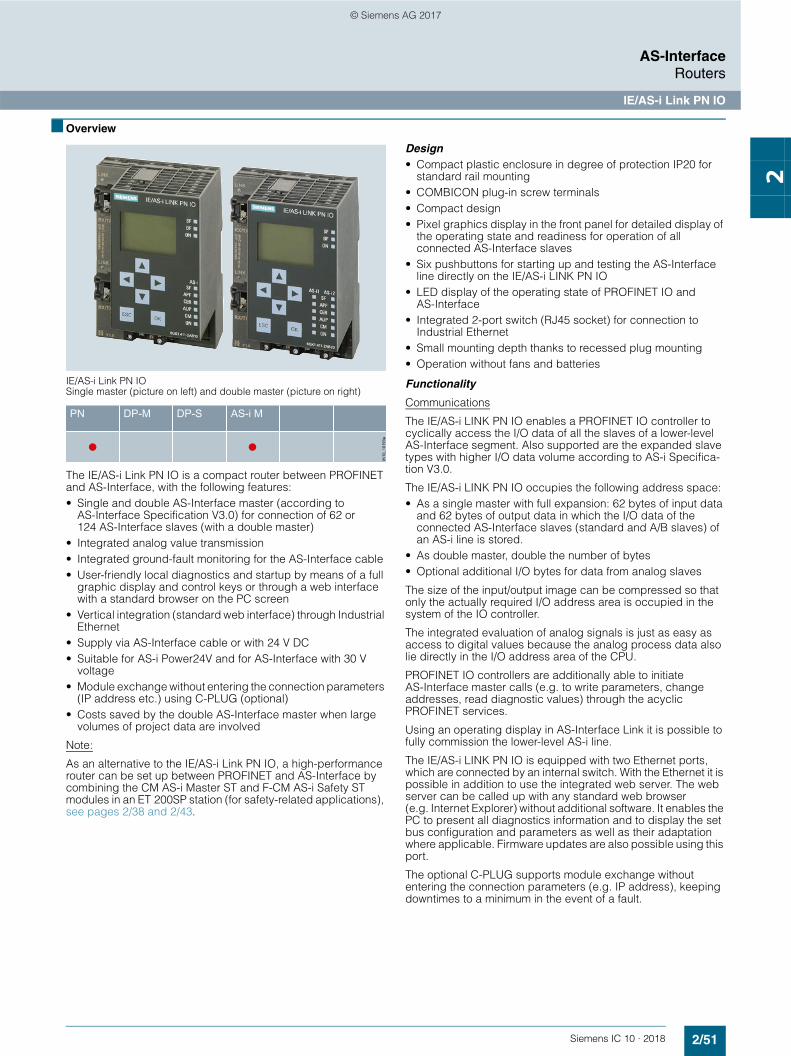
2/51Siemens IC 10 · 2018
AS-InterfaceRouters
IE/AS-i Link PN IO
2
■ Overview
IE/AS-i Link PN IO Single master (picture on left) and double master (picture on right)
The IE/AS-i Link PN IO is a compact router between PROFINET and AS-Interface, with the following features:• Single and double AS-Interface master (according to
AS-Interface Specification V3.0) for connection of 62 or 124 AS-Interface slaves (with a double master)
• Integrated analog value transmission• Integrated ground-fault monitoring for the AS-Interface cable• User-friendly local diagnostics and startup by means of a full
graphic display and control keys or through a web interface with a standard browser on the PC screen
• Vertical integration (standard web interface) through Industrial Ethernet
• Supply via AS-Interface cable or with 24 V DC• Suitable for AS-i Power24V and for AS-Interface with 30 V
voltage• Module exchange without entering the connection parameters
(IP address etc.) using C-PLUG (optional)• Costs saved by the double AS-Interface master when large
volumes of project data are involved
Note:
As an alternative to the IE/AS-i Link PN IO, a high-performance router can be set up between PROFINET and AS-Interface by combining the CM AS-i Master ST and F-CM AS-i Safety ST modules in an ET 200SP station (for safety-related applications), see pages 2/38 and 2/43.
Design• Compact plastic enclosure in degree of protection IP20 for
standard rail mounting• COMBICON plug-in screw terminals• Compact design• Pixel graphics display in the front panel for detailed display of
the operating state and readiness for operation of all connected AS-Interface slaves
• Six pushbuttons for starting up and testing the AS-Interface line directly on the IE/AS-i LINK PN IO
• LED display of the operating state of PROFINET IO and AS-Interface
• Integrated 2-port switch (RJ45 socket) for connection to Industrial Ethernet
• Small mounting depth thanks to recessed plug mounting• Operation without fans and batteries
Functionality
Communications
The IE/AS-i LINK PN IO enables a PROFINET IO controller to cyclically access the I/O data of all the slaves of a lower-level AS-Interface segment. Also supported are the expanded slave types with higher I/O data volume according to AS-i Specifica-tion V3.0.
The IE/AS-i LINK PN IO occupies the following address space:• As a single master with full expansion: 62 bytes of input data
and 62 bytes of output data in which the I/O data of the connected AS-Interface slaves (standard and A/B slaves) of an AS-i line is stored.
• As double master, double the number of bytes • Optional additional I/O bytes for data from analog slaves
The size of the input/output image can be compressed so that only the actually required I/O address area is occupied in the system of the IO controller.
The integrated evaluation of analog signals is just as easy as access to digital values because the analog process data also lie directly in the I/O address area of the CPU.
PROFINET IO controllers are additionally able to initiate AS-Interface master calls (e.g. to write parameters, change addresses, read diagnostic values) through the acyclic PROFINET services.
Using an operating display in AS-Interface Link it is possible to fully commission the lower-level AS-i line.
The IE/AS-i LINK PN IO is equipped with two Ethernet ports, which are connected by an internal switch. With the Ethernet it is possible in addition to use the integrated web server. The web server can be called up with any standard web browser (e.g. Internet Explorer) without additional software. It enables the PC to present all diagnostics information and to display the set bus configuration and parameters as well as their adaptation where applicable. Firmware updates are also possible using this port.
The optional C-PLUG supports module exchange without entering the connection parameters (e.g. IP address), keeping downtimes to a minimum in the event of a fault.
IK10
_101
93a
AS-i MDP-SDP-MPN
© Siemens AG 2017
2/52 Siemens IC 10 · 2018
AS-InterfaceRouters
IE/AS-i Link PN IO
2
Diagnostics
The following diagnostics is possible using the display and control keys, web interface or STEP 7:• Operating state of the IE/AS-i LINK PN IO• State of the link as a PROFINET IO device• Diagnostics of the AS-Interface network• Message frame statistics• Standard diagnostics pages in the web interface for fast
diagnostics access through Ethernet using a standard browser
• Reporting of diagnostic events is optionally possible via e-mail or SNMP trap. The integrated diagnostic buffer saves the events including time stamp
Notes on security
In order to protect plants, systems, machines and networks against cyber threats, it is necessary to implement – and contin-uously maintain – a holistic, state-of-the-art industrial security concept. Siemens products and solutions represent only one component of such a concept.
For more information about the subject of Industrial Security, see www.siemens.com/industrialsecurity.
Configuration
The IE/AS-i LINK PN IO is configured as follows:• With STEP 7 (classic) V5.4 or higher: When configuring in
STEP 7, the AS-Interface configuration can be uploaded in STEP 7 V5.4 SP2 and higher. Furthermore, AS-Interface slaves from Siemens can also be conveniently configured in HW Config (slave selection dialog).
• Alternatively, IE/AS-i LINK PN IO can be integrated by means of the PROFINET GSD file in the engineering tool (e.g. for TIA Portal, for STEP 7 versions V5.4 SP2 and lower, or for non-Siemens engineering tools).
Please observe the configuration notes in the TIA Portal, see https://support.industry.siemens.com/cs/ww/en/view/109483764.
■ Benefits
• Short startup times through simple configuration at the press of a button and testing of the AS-Interface line using the display or web interface
• Reduction of standstill and servicing times in the event of a slave failure thanks to user-friendly diagnostics using the display or web interface
• Costs saved by the double AS-Interface master when large volumes of project data are involved
• No need for an AS-i power supply with AS-i Power24V:The AS-Interface cable is fed through an existing 24 V DC PELV power supply unit. For decoupling, an AS-i data decoupling module is required; see page 2/85
• Standard mode with AS-Interface power supply (see page 2/79) possible without restrictions, whereby no further operational voltage is required
• For diagnostics during ongoing operation, diagnostics blocks with clearly arranged visualization on the SIMATIC HMI panel are available or can be downloaded free of charge via a web browser, see https://support.industry.siemens.com/cs/ww/en/view/61892138
© Siemens AG 2017

2/53Siemens IC 10 · 2018
AS-InterfaceRouters
IE/AS-i Link PN IO
2
■ Application
The DP/AS-i Link PN IO is a PROFINET IO device (according to IEC 61158/IEC 61784) and an AS-Interface master (based on AS-Interface Specification V3.0 according to IEC 62026-2). It enables transparent data access to AS-Interface from PROFINET.
Exchanging data with PROFINET IO controllers
PROFINET IO controllers can exchange I/O data with AS-Interface in cyclic mode and can perform AS-i master calls in addition with acyclic services (e.g. reading/writing the AS-i configuration during normal operation). The IE/AS-i LINK PN IO is therefore suitable for distributed configurations and for integrating a lower-level AS-Interface network.
Single master
The AS-i single master version of IE/AS-i i LINK PN IO is suitable for applications with typical volumes of data. The single master can operate up to 248 DI/248 DO, using 62 A/B slaves with 4 DI/4 DO each.
Double master
The AS-i double master version of IE/AS-i LINK PN IO is suitable for applications with large volumes of data. In this case, twice the volume of project data can be used on two AS-i lines running independently of each other. The double master can operate up to 496 DI/496 DQ, using two AS-i networks each with 62 A/B slaves with 4 DI/4 DQ each.
Integration of AS-Interface on PROFINET through IE/AS-i LINK PN IO as single/double master
Power supply
Power supply
When IE/AS-i Link PN IO is usedas double master
SlaveSlave
Safeslave with EMERGENCY- STOP
Safeslave with EMERGENCY- STOP
Laserscanner
3RA2 load feeders
IE/AS-i Link PN IO
ET 200pro
ET 200SP
IK10
_400
17c
SCALANCEXC208
Industrial Ethernet
PROFINET
AS-Interface AS-Interface
MSS ASIsafe
MSS ASIsafe
SIMATICSoftware Controller
SIMATIC HMI
SIMATIC/SIMOTION
© Siemens AG 2017

2/54 Siemens IC 10 · 2018* You can order this quantity or a multiple thereof.
Illustrations are approximate
AS-InterfaceRouters
IE/AS-i Link PN IO
2
Wireless communication
Using an upstream IWLAN client module, e.g. SCALANCE W748-1 RJ45, an AS-Interface line can be integrated in the PROFINET world by wireless means.
Sample uses are applications which up to now have been performed with fault-prone tow chain or collector wire technology. Maintenance costs are thus reduced.
Wireless communication between Industrial Ethernet and AS-Interface components
■ Selection and ordering data
■ Accessories
■ More information
Version SD Article No. Priceper PU
PU(UNIT,
SET, M)
PS* PG
d
IE/AS-i Link PN IO
IE/AS-i Link PN IO
Router between PROFINET and AS-Interface in degree of protection IP20; including COMBICON plug-in screw terminals for connecting an AS-Interface cable (two AS-Interface cables for a double master) and the optional 24 V supply; complies with AS-Interface Specification V3.0; dimensions (W x H x D/mm): 90 x 132 x 88.5
COMBICON connection
• Single master with display } 6GK1411-2AB10 1 1 unit 42C• Double master with display } 6GK1411-2AB20 1 1 unit 42C
Version SD Article No. Priceper PU
PU(UNIT,
SET, M)
PS* PG
dC-PLUG 1 6GK1900-0AB00 1 1 unit 5N3Exchange medium for simple exchange of devices in the event of a fault; for accommodating configuration and application data; can be used in SIMATIC NET products with a C-PLUG slotIE FC RJ45 Plug 90
RJ45 plug-in connector for Industrial Ethernet, with robust metal enclosure and integrated insulation displacement contacts for connection of Industrial Ethernet FC installation cables; with 90° cable feeder• 1 pack = 1 unit 1 6GK1901-1BB20-2AA0 1 1 unit 5K1• 1 pack = 10 units 1 6GK1901-1BB20-2AB0 1 10 units 5K1• 1 pack = 50 units 1 6GK1901-1BB20-2AE0 1 50 units 5K1
More information
Manuals, see https://support.industry.siemens.com/cs/ww/en/ps/15762/man AS-i block library for SIMATIC PCS 7 for easy connection of AS-Interface to PCS 7, see from page 14/23 onwards
IE/AS-iLinkPN IO
AS-Interface
IE/AS-iLinkPN IO
AS-Interface
IE/AS-iLinkPN IO
AS-Interface
Radio cell 1
Driverless transportation system (AGVS)
Radio cell 2 S7-400 with CP 443-1
Industrial Ethernet
PROFINET
SIMATIC HMI
Field PG
Access PointSCALANCEW788-2 M12
Access PointSCALANCEW788-2 M12
Client ModuleSCALANCEW748-1 RJ45
Client ModuleSCALANCEW748-1 RJ45
Client ModuleSCALANCEW748-1 RJ45
IK10
_301
43d
S7-1500
© Siemens AG 2017

2/55Siemens IC 10 · 2018
AS-InterfaceSlaves
I/O Modules for Use in the Field, High Degree of Protection
Digital I/O modules, IP67 – Introduction
2
■ Overview
K60
K45
K20
Three coordinated series of AS-Interface compact modules with digital and analog compact modules and a high degree of protection are available for use in the field:• Series K60 (digital and analog)• Series K45 (digital)• Series K20 (digital)
All compact modules are characterized by particularly simple handling. The K60 and K45 modules are mounted with a mounting plate. The mounting plate is used to mount the AS-Interface flat cables and enables mounting on a wall or standard mounting rail.
The particularly narrow K20 modules are directly mounted without a mounting plate and connected to the AS-Interface using a round cable.
Connection types
For flexible connection of different sensors and actuators, the following PIN assignments are available on the I/O modules with M12 sockets:
Standard assignment
With the standard assignment, one sensor/actuator is connected per M12 socket. In this case the signal for the outputs is acquired at PIN4 while the signal for the inputs is acquired at PIN4 and PIN2. As the result, sensors can be connected directly to PIN2 and PIN4.
Y assignment
With the Y assignment, two sensors or two actuators can be connected to one M12 socket. In this case, both PIN4 and PIN2 are provided for one sensor signal and one actuator signal on each M12 socket.
Y-II assignment
The Y-II assignment offers the following options:• Individual connection of a sensor/actuator to one M12 socket• Connection of two sensors/actuators to one M12 socket as
follows:- The signal of the first sensor/actuator is connected to PIN4 of
the first socket.- The signal of the second sensor/actuator is connected to
PIN2 of the first socket and to PIN4 of the second socket. In this case, the second socket is not required and is closed with a sealing cap.
Overview of digital compact modules
The following table provides an overview of the important features of the digital compact modules..
✓ Available-- Not available
Version K60 K45 K20
8 inputs/2 outputs ✓ -- --8 inputs ✓ ✓ --4 inputs/4 outputs ✓ ✓ ✓
4 inputs/3 outputs ✓ -- --4 inputs/2 outputs ✓ -- --4 inputs ✓ ✓ ✓
2 inputs/2 outputs -- ✓ ✓
4 outputs ✓ ✓ ✓
3 outputs -- ✓ --AS-Interface connection Flat cable/
round cableFlat cable Round cable
I/O connection method M12 M12/M8 M12/M8Pin assignment Standard/Y-II/Y Standard/Y Standard/YDegree of protection IP65/IP67/IP68/IP69K IP65/IP67 IP65/IP67ATEX 3D (Zone 22) ✓ -- --Extended address mode
✓ ✓ ✓
© Siemens AG 2017

2/56 Siemens IC 10 · 2018
AS-InterfaceSlavesI/O Modules for Use in the Field, High Degree of Protection
Digital I/O modules, IP67 – K60
2
■ Overview
K60
The K60 digital AS-Interface compact modules are character-ized by optimized handling characteristics and user-friendli-ness. They permit the mounting times and startup times of AS-Interface to be reduced by up to 40 %.
Mounting and connection of the AS-Interface shaped cables
Assembly of the K60 modules is performed with a mounting plate which accommodates the AS-Interface shaped cables. Two different mounting plates are offered for• Wall mounting• Standard rail mounting
The mounting plate and the compact module are joined together by means of a screw, with simultaneous contacting of the AS-Interface cable by the service-proven insulation piercing method.
Addressing and connection of the sensors/actuators
Addressing of the K60 modules is performed using an addressing socket integrated in the compact module. The addresses can also be assigned after installation.
K60 modules with a maximum of four digital inputs and outputs
These compact modules contain the M12 standard connections for inputs and outputs. Using M12 standard connectors, a maximum of four sensors and four actuators can be connected to the compact module.
K60 compact modules with a maximum of eight digital inputs
These modules have eight digital inputs for connection through M12 plugs.
The module requires two AS-Interface addresses for processing all eight inputs. The addressing can thus be performed through a double addressing socket integrated in the module.
K60 compact modules with four digital inputs and outputs according to AS-Interface Specification 3.0
The AS-Interface Specification V3.0 extended address mode (A/B addresses) enables connection of up to 62 slaves on one AS-Interface network. With the extended address mode, four outputs are now possible even with A/B slaves (instead of only three outputs possible up to now with Specification V2.1). Hence with full expansion of an AS-Interface network, there are now 248 inputs as well as 248 outputs available on one AS-i network.
Points to bear in mind: • These modules can be used only with a master according to
AS-i Specification V3.0. • The cycle times for the outputs may be up to 20 ms.
K60 data couplers
An AS-Interface data coupler has been added to the K60 compact module range. Integrated in this module are two AS-i slaves which are connected to two different AS-i networks. Each of the two integrated slaves has four virtual inputs and four virtual outputs. The bidirectional data transmission of four data bits between two AS-i networks is thus possible in a simple and cost-effective manner. The data coupler needs its own address in each AS-i network.
Each AS-i network works with a different cycle time depending on the number of stations. Hence two AS-i networks are not necessarily synchronous. For this reason, the AS-i data coupler can be used to transmit only standard data and no safety data.
K60 compact modules for use in hazardous areas (ATEX)
Two versions of the K60 modules are available for operation in Zone 22 hazardous areas according to Classification II 3D (dusty atmosphere, non-conductive dust). The version with four inputs and four outputs has the designation (Ex) II 3D Ex tD A22 IP65X T75°C and the version with four inputs has the designation (Ex) II 3D Ex tD A22 IP65X T60°C.
Special conditions have to be observed for the safe operation of these devices. In particular the module must be protected by suitable measures from mechanical damage.
© Siemens AG 2017

2/57Siemens IC 10 · 2018* You can order this quantity or a multiple thereof.Illustrations are approximate
AS-InterfaceSlaves
I/O Modules for Use in the Field, High Degree of Protection
Digital I/O modules, IP67 – K60
2
■ Selection and ordering data
1) Module occupies two AS-Interface addresses
Version SD Article No. Priceper PU
PU(UNIT,
SET, M)
PS* PG
d
3RK1400-1DQ00-0AA3
Digital I/O modules, IP67 – K60
• PNP transistor• Width 60 mm• Connection method: M12• Modules supplied without mounting plateType Current
carrying capacity of outputs
Slave type Pin assign-ment
Sensor power supply via
8 inputs/2 outputs1)
2 A A/B Special AS-i 2 3RK2400-1HQ00-0AA3 1 1 unit 42C
8 inputs1) -- Standard Y-II AS-i } 3RK1200-0DQ00-0AA3 1 1 unit 42C-- A/B Y-II AS-i } 3RK2200-0DQ00-0AA3 1 1 unit 42C-- A/B Y-II Uaux 5 3RK2200-1DQ00-1AA3 1 1 unit 42C
4 inputs/4 outputs
2 A Standard Y-II AS-i } 3RK1400-1DQ00-0AA3 1 1 unit 42C2 A Standard Standard AS-i } 3RK1400-1CQ00-0AA3 1 1 unit 42C1 A Standard Y-II AS-i 2 3RK1400-1DQ01-0AA3 1 1 unit 42C1 A Standard Standard AS-i } 3RK1400-1DQ03-0AA3 1 1 unit 42C2 A A/B (Spec. V3.0) Y-II AS-i 2 3RK2400-1DQ00-0AA3 1 1 unit 42C2 A A/B (Spec. V3.0) Y-II Uaux 2 3RK2400-1DQ00-1AA3 1 1 unit 42C
4 inputs/3 outputs
2 A A/B Y-II AS-i } 3RK2400-1FQ03-0AA3 1 1 unit 42C
4 inputs/2 outputs
2 A Standard Y-II AS-i } 3RK1400-1MQ00-0AA3 1 1 unit 42C
4 inputs -- Standard Y-II AS-i } 3RK1200-0CQ00-0AA3 1 1 unit 42C-- A/B Y-II AS-i 2 3RK2200-0CQ00-0AA3 1 1 unit 42C
2 x 2 inputs/ 2 x 2 outputs
1 A Standard Y AS-i 15 3RK1400-1DQ02-0AA3 1 1 unit 42C
4 outputs 2 A Standard Y-II -- } 3RK1100-1CQ00-0AA3 1 1 unit 42C2 A A/B (Spec. V3.0) Y-II -- 2 3RK2100-1CQ00-0AA3 1 1 unit 42C
Digital I/O modules IP67 – K60, version ATEX (Ex) II 3D Ex tD A22 IP65X T70 °C/60 °C
• PNP transistor • Width 60 mm• Current carrying capacity of the inputs: 200 mA • Connection method: M12 • Modules supplied without mounting plateType Current carrying capacity
of outputsSlave type
Pin assignment
4 inputs/4 outputs
2 A Standard Y-II 5 3RK1400-1DQ05-0AA3 1 1 unit 42C
4 inputs -- Standard Y-II 10 3RK1200-0CQ05-0AA3 1 1 unit 42CDigital I/O modules IP67 – K60 data couplers• Modules supplied without mounting plateType Current carrying capacity
of outputsSlave type
Pin assignment
Data coupler 4 inputs/4 outputs (virtual)
-- Standard -- 10 3RK1408-8SQ00-0AA3 1 1 unit 42C
© Siemens AG 2017

2/58 Siemens IC 10 · 2018* You can order this quantity or a multiple thereof.
Illustrations are approximate
AS-InterfaceSlavesI/O Modules for Use in the Field, High Degree of Protection
Digital I/O modules, IP67 – K60
2
■ Accessories
Version SD Article No. Priceper PU
PU(UNIT,
SET, M)
PS* PG
d
3RK1901-0CA00
K60 mounting platesSuitable for all K60 compact modules• Wall mounting } 3RK1901-0CA00 1 1 unit 42C• Standard rail mounting } 3RK1901-0CB01 1 1 unit 42C
3RK1901-1KA00
AS-Interface sealing caps M12For free M12 sockets
} 3RK1901-1KA00 100 10 units 42C
3RK1902-0AR00
Sealing sets
• For K60 mounting plate and standard distributor• Cannot be used for K45 mounting plate• One set contains one straight and one shaped seal
2 3RK1902-0AR00 100 5 units 42D
© Siemens AG 2017
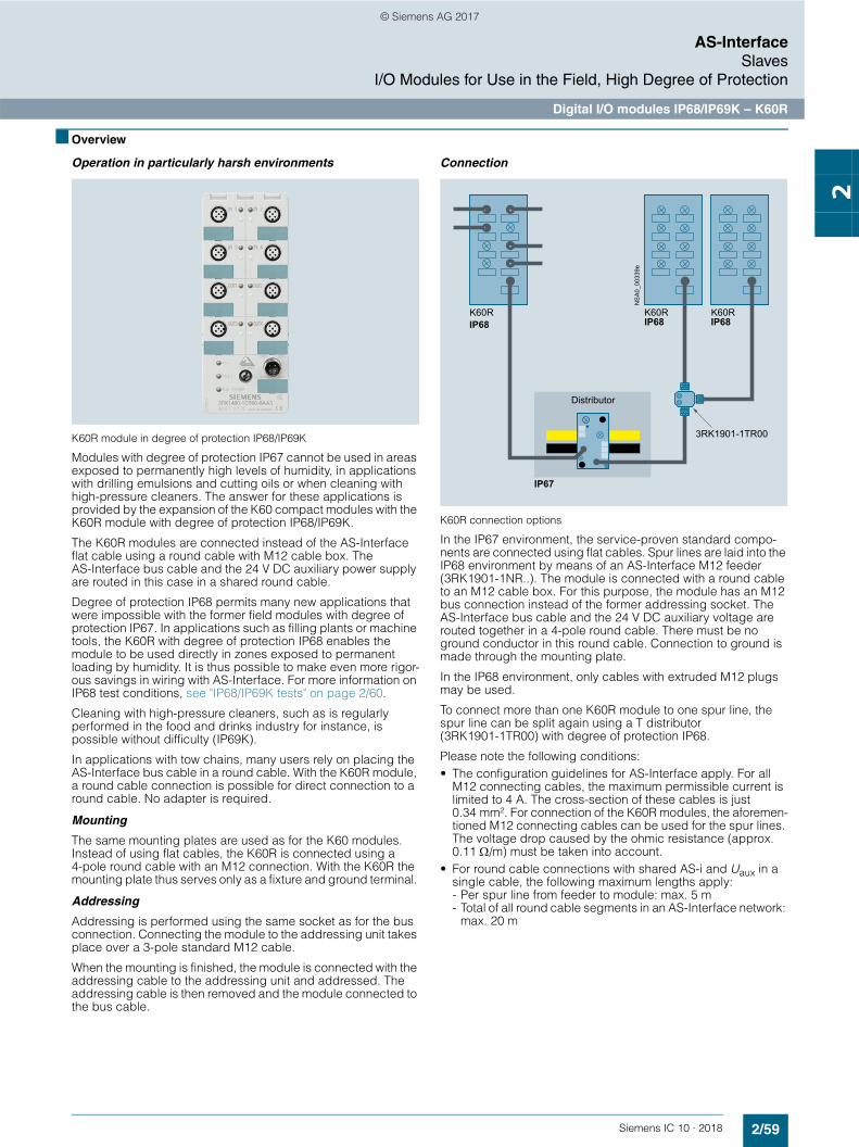
2/59Siemens IC 10 · 2018
AS-InterfaceSlaves
I/O Modules for Use in the Field, High Degree of Protection
Digital I/O modules IP68/IP69K – K60R
2
■ Overview
Operation in particularly harsh environments
K60R module in degree of protection IP68/IP69K
Modules with degree of protection IP67 cannot be used in areas exposed to permanently high levels of humidity, in applications with drilling emulsions and cutting oils or when cleaning with high-pressure cleaners. The answer for these applications is provided by the expansion of the K60 compact modules with the K60R module with degree of protection IP68/IP69K.
The K60R modules are connected instead of the AS-Interface flat cable using a round cable with M12 cable box. The AS-Interface bus cable and the 24 V DC auxiliary power supply are routed in this case in a shared round cable.
Degree of protection IP68 permits many new applications that were impossible with the former field modules with degree of protection IP67. In applications such as filling plants or machine tools, the K60R with degree of protection IP68 enables the module to be used directly in zones exposed to permanent loading by humidity. It is thus possible to make even more rigor-ous savings in wiring with AS-Interface. For more information on IP68 test conditions, see "IP68/IP69K tests" on page 2/60.
Cleaning with high-pressure cleaners, such as is regularly performed in the food and drinks industry for instance, is possible without difficulty (IP69K).
In applications with tow chains, many users rely on placing the AS-Interface bus cable in a round cable. With the K60R module, a round cable connection is possible for direct connection to a round cable. No adapter is required.
Mounting
The same mounting plates are used as for the K60 modules. Instead of using flat cables, the K60R is connected using a 4-pole round cable with an M12 connection. With the K60R the mounting plate thus serves only as a fixture and ground terminal.
Addressing
Addressing is performed using the same socket as for the bus connection. Connecting the module to the addressing unit takes place over a 3-pole standard M12 cable.
When the mounting is finished, the module is connected with the addressing cable to the addressing unit and addressed. The addressing cable is then removed and the module connected to the bus cable.
Connection
K60R connection options
In the IP67 environment, the service-proven standard compo-nents are connected using flat cables. Spur lines are laid into the IP68 environment by means of an AS-Interface M12 feeder (3RK1901-1NR..). The module is connected with a round cable to an M12 cable box. For this purpose, the module has an M12 bus connection instead of the former addressing socket. The AS-Interface bus cable and the 24 V DC auxiliary voltage are routed together in a 4-pole round cable. There must be no ground conductor in this round cable. Connection to ground is made through the mounting plate.
In the IP68 environment, only cables with extruded M12 plugs may be used.
To connect more than one K60R module to one spur line, the spur line can be split again using a T distributor (3RK1901-1TR00) with degree of protection IP68.
Please note the following conditions: • The configuration guidelines for AS-Interface apply. For all
M12 connecting cables, the maximum permissible current is limited to 4 A. The cross-section of these cables is just 0.34 mm². For connection of the K60R modules, the aforemen-tioned M12 connecting cables can be used for the spur lines. The voltage drop caused by the ohmic resistance (approx. 0.11 /m) must be taken into account.
• For round cable connections with shared AS-i and Uaux in a single cable, the following maximum lengths apply:- Per spur line from feeder to module: max. 5 m- Total of all round cable segments in an AS-Interface network:
max. 20 m
Distributor
IP68 IP68 IP68
NS
A0_
0033
9e
K60R K60RK60R
IP67
3RK1901-1TR00
© Siemens AG 2017

2/60 Siemens IC 10 · 2018* You can order this quantity or a multiple thereof.
Illustrations are approximate
AS-InterfaceSlavesI/O Modules for Use in the Field, High Degree of Protection
Digital I/O modules IP68/IP69K – K60R
2
IP68/IP69K tests
K60R modules were tested with the following tests:• Stricter test than IP67: 90 min at 1.8 m depth of water
(IP67: 30 min at 1 m depth of water)• Salt water test: Five months in salt water, 20 cm deep, at room
temperature• Test with particularly creepable oil: Five months completely
under oil at room temperature• Test with drilling emulsion: Five months at room temperature
(components of the drilling emulsion: Anionic and non-ionic emulsifiers, paraffinic low-aromatic mineral oil, boric acid alkanolamines, corrosion inhibitors, oil content 40 %)
• Test in oil bath (Excellence 416 oil) with alternating oil bath temperature: 130 cycles of 15 to 55 °C, two months
• Cleaning with a high-pressure cleaner according to IP69K: 80 to 100 bar, 10 to 15 cm distance, time per side > 30 s, water temperature 80 °C
To simulate requirements as realistically as possible, the modules were artificially aged prior to the tests by 15 temperature cycles of -25/+85 °C. During the test, the modules were connected to 3RX1 connecting cables. Unassigned connections were closed with 3RK1901-1KA00 sealing caps.
Note:
Sealing caps and M12 connections must be tightened with the correct torque.
■ Selection and ordering data
Version SD Article No. Priceper PU
PU(UNIT,
SET, M)
PS* PG
d
3RK1400-1CR00-0AA3
Digital I/O modules IP68/IP69K – K60R
• 4 inputs/4 outputs• Width 60 mm• IP68/IP69K• Standard assignment• Current carrying capacity
- 200 mA (inputs)- 2 A (outputs)
• Standard slave• Modules supplied without mounting plate
2 3RK1400-1CR00-0AA3 1 1 unit 42C
© Siemens AG 2017

2/61Siemens IC 10 · 2018* You can order this quantity or a multiple thereof.Illustrations are approximate
AS-InterfaceSlaves
I/O Modules for Use in the Field, High Degree of Protection
Digital I/O modules IP68/IP69K – K60R
2
■ Accessories
Version SD Article No. Priceper PU
PU(UNIT,
SET, M)
PS* PG
d
3RK1901-0CA00
K60 mounting platesSuitable for all K60 and K60R compact modules• Wall mounting } 3RK1901-0CA00 1 1 unit 42C• Standard rail mounting } 3RK1901-0CB01 1 1 unit 42C
3RK1901-1KA00
AS-Interface sealing caps M12
For free M12 sockets} 3RK1901-1KA00 100 10 units 42C
3RK1901-1NR21
AS-Interface M12 feeders, current carrying capacity up to 4 A
For flat cable For Cable length
Cable end in feeder
AS-i/Uaux M12 socket -- Not available 2 3RK1901-1NR20 1 1 unit 42CAS-i/Uaux M12 cable box
M12 cable box1 m Not available 2 3RK1901-1NR21 1 1 unit 42C
AS-i/Uaux 2 m Not available 2 3RK1901-1NR22 1 1 unit 42C
3RK1901-1NR04
AS-Interface M12 feeders, 4-fold, current carrying capacity up to 4 A
For flat cable For Cable length
Cable end in feeder
AS-i/Uaux 4-fold M12 socket, delivery includes mounting plate (for wall and standard rail mounting)
-- Not available 2 3RK1901-1NR04 1 1 unit 42C
3RK1901-1TR00
M12 T distributors
• IP68• 1 x M12 plug• 2 x M12 box
10 3RK1901-1TR00 1 1 unit 42C
3RK1902-4PB15-3AA0
M12 connecting cables
• 3-pole• For addressing AS-i slaves with M12 bus connection• Cable length 1.5 m
10 3RK1902-4PB15-3AA0 1 1 unit 42D
© Siemens AG 2017

2/62 Siemens IC 10 · 2018
AS-InterfaceSlavesI/O Modules for Use in the Field, High Degree of Protection
Digital I/O modules, IP67 – K45
2
■ Overview
Compact modules K45
The K45 series of compact modules supplements the large K60 compact modules which have a proven track record in industry. They are the logical consequence for rounding off the bottom end of the existing product range.
The acclaimed advantages of the existing K60 compact mod-ules are fully emulated by the K45 modules. The K45 modules have a substantially smaller basic area and installation depth, however.
Yet in spite of these small dimensions all the modules have large labels and an integrated addressing socket.
Two mounting plates are offered for the K45 compact modules:• Mounting plate for wall mounting
This has a hole pattern that is identical to that of the K60 com-pact modules. This means that K60 compact modules can be mounted together with K45 modules in an aligned arrange-ment. The shaped cables can be inserted in the recesses of the mounting plates where they cause no hindrance.
• Mounting plate for standard rail mounting
Connection of the AS-Interface shaped cables
The mounting plate and the compact module are joined together by means of a screw, with simultaneous contacting of the AS-Interface cable by the service-proven insulation piercing method.
Now, mounting the AS-Interface shaped cables is in fact easier than ever. The yellow and black AS-Interface shaped cable can be inserted into the mounting plates from the left or right regard-less of the position of the coding lug. The correct polarity of the applied voltages is thus guaranteed.
Addressing and connection of the sensors/actuators
Addressing of the K45 compact modules is performed using an addressing socket integrated in the module. The addresses can be assigned even when mounted.
K45 modules with a maximum of four digital inputs and outputs
These compact modules contain up to four M12 standard connections or M8 standard connections for inputs and outputs. Using M12 or M8 standard connectors, a maximum of four sensors and four actuators can be connected to the compact module. Depending on the module, the sockets can be assigned in duplicate. Pin assignment: Y i.e. via a socket, two sensors or one sensor/one actuator are connected.
K45 modules with a maximum of eight digital inputs
These modules have eight digital inputs for connection through M12 plugs. The sockets have duplicate assignments. Pin assignment: Y i.e. via a socket, two sensors or one sensor/one actuator are connected.
The module requires two AS-Interface addresses for processing all eight inputs. The addresses can be assigned through a double addressing socket integrated in the module.
K45 modules in compliance with AS-i Specification V3.0 with four digital inputs and outputs/four digital outputs
The extended address mode (A/B addresses) according to AS-Interface Specification V3.0 enables connection of up to 62 slaves on one AS-i network. With this extended address mode, four outputs are now possible even with A/B slaves (instead of only three outputs possible up to now with Specification V2.1). Hence with full expansion of an AS-Interface network, there are now 248 inputs as well as 248 outputs available on one AS-Interface system.
Points to bear in mind: • These modules can be used only with a master according to
AS-i Specification V3.0. • The cycle times for the outputs may be up to 20 ms.
Depending on the module, the sockets can be assigned in duplicate.Pin assignment: Y i.e. via a socket, two sensors or one sensor/one actuator are connected.
© Siemens AG 2017

2/63Siemens IC 10 · 2018* You can order this quantity or a multiple thereof.Illustrations are approximate
AS-InterfaceSlaves
I/O Modules for Use in the Field, High Degree of Protection
Digital I/O modules, IP67 – K45
2
■ Selection and ordering data
✓ Available
-- Not available
1) Module occupies two AS-Interface addresses2) The typical current carrying capacity per output increases with version
"E12" from 1.5 to 2 A (available since approx. 07/2003).
■ Accessories
Version SD Article No. Priceper PU
PU(UNIT,
SET, M)
PS* PG
d
3RK1400-0GQ20-0AA3
Digital I/O modules, IP67 – K45
• PNP transistor• Width 45 mm• Current carrying capacity of the inputs: 200 mA• Modules supplied without mounting plateType Current
carry-ing capac-ity of outputs
Slave type Pin assign-ment
Uaux 24 V
Connec-tion methods
8 inputs1) -- A/B Y -- M12 2 3RK2200-0DQ20-0AA3 1 1 unit 42C4 inputs -- Standard Standard -- M12 } 3RK1200-0CQ20-0AA3 1 1 unit 42C
-- Standard Standard -- M8 2 3RK1200-0CT20-0AA3 1 1 unit 42C-- A/B Standard -- M12 } 3RK2200-0CQ20-0AA3 1 1 unit 42C-- A/B Standard -- M8 5 3RK2200-0CT20-0AA3 1 1 unit 42C
2 x 2 inputs -- A/B Y -- M12 2 3RK2200-0CQ22-0AA3 1 1 unit 42C2 inputs/2 outputs
2 A2) Standard Standard ✓ M12 } 3RK1400-1BQ20-0AA3 1 1 unit 42C
2 x (1 input/1 output)
0.2 A Standard Y -- M12 2 3RK1400-0GQ20-0AA3 1 1 unit 42C
4 x (1 input/1 output)
0.2 A A/B (Spec. V3.0)
Y -- M12 5 3RK2400-0GQ20-0AA3 1 1 unit 42C
0.5 A A/B (Spec. V3.0)
Y ✓ M12 5 3RK2400-1GQ20-1AA3 1 1 unit 42C
4 outputs 1 A A/B (Spec. V3.0)
Standard ✓ M12 2 3RK2100-1CQ20-0AA3 1 1 unit 42C
3 outputs 1 A A/B Standard ✓ M12 } 3RK2100-1EQ20-0AA3 1 1 unit 42C4 outputs 1 A Standard Standard ✓ M12 } 3RK1100-1CQ20-0AA3 1 1 unit 42C2 outputs/2 inputs
2 A A/B Standard ✓ M12 2 3RK2400-1BQ20-0AA3 1 1 unit 42C
Version SD Article No. Priceper PU
PU(UNIT,
SET, M)
PS* PG
d
3RK1901-2EA00
K45 mounting plates
• For wall mounting } 3RK1901-2EA00 1 1 unit 42C• For standard rail mounting } 3RK1901-2DA00 1 1 unit 42C
3RK1901-1MN00
Cable termination pieces
For sealing of open cable ends (shaped AS-Interface cable) in IP67
} 3RK1901-1MN00 1 10 units 42C
3RK1901-1KA00
3RK1901-1PN00
AS-Interface sealing caps
• For free M12 sockets } 3RK1901-1KA00 100 10 units 42C• For free M8 sockets 2 3RK1901-1PN00 100 10 units 42C
© Siemens AG 2017
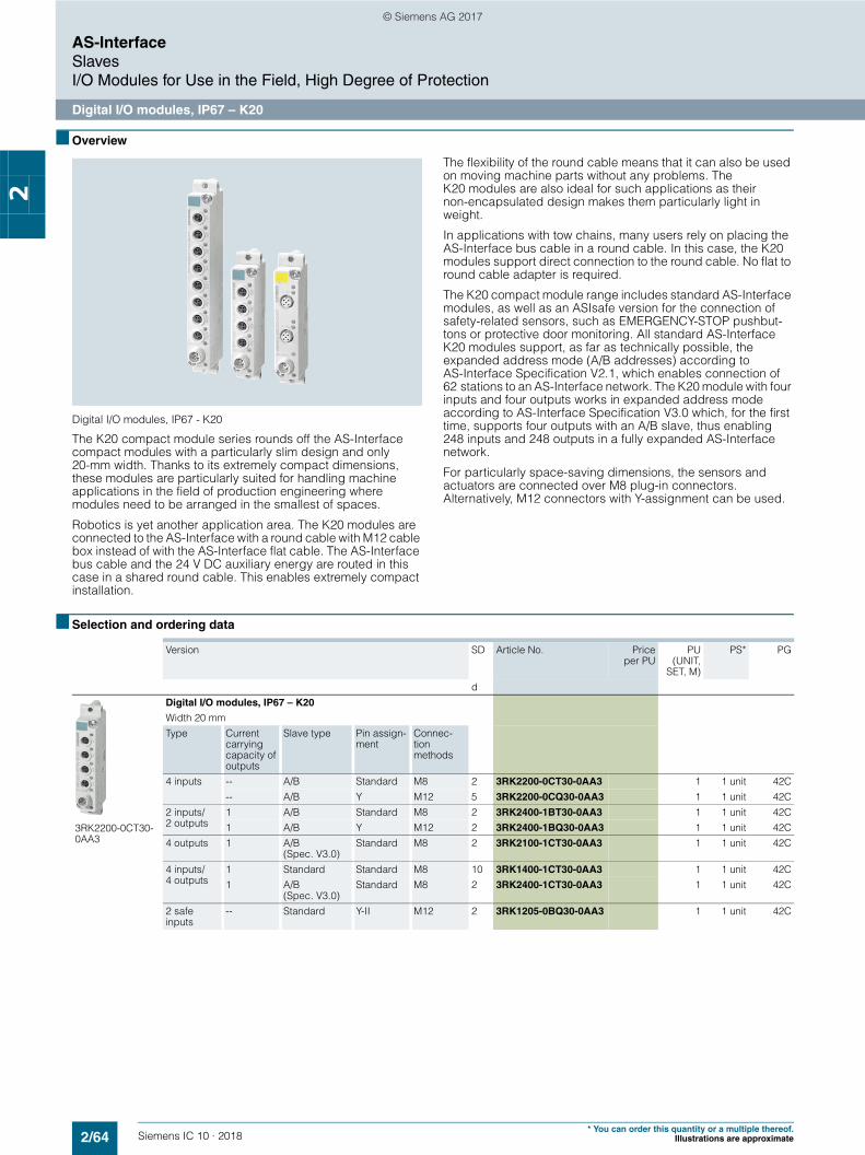
2/64 Siemens IC 10 · 2018* You can order this quantity or a multiple thereof.
Illustrations are approximate
AS-InterfaceSlavesI/O Modules for Use in the Field, High Degree of Protection
Digital I/O modules, IP67 – K20
2
■ Overview
Digital I/O modules, IP67 - K20
The K20 compact module series rounds off the AS-Interface compact modules with a particularly slim design and only 20-mm width. Thanks to its extremely compact dimensions, these modules are particularly suited for handling machine applications in the field of production engineering where modules need to be arranged in the smallest of spaces.
Robotics is yet another application area. The K20 modules are connected to the AS-Interface with a round cable with M12 cable box instead of with the AS-Interface flat cable. The AS-Interface bus cable and the 24 V DC auxiliary energy are routed in this case in a shared round cable. This enables extremely compact installation.
The flexibility of the round cable means that it can also be used on moving machine parts without any problems. The K20 modules are also ideal for such applications as their non-encapsulated design makes them particularly light in weight.
In applications with tow chains, many users rely on placing the AS-Interface bus cable in a round cable. In this case, the K20 modules support direct connection to the round cable. No flat to round cable adapter is required.
The K20 compact module range includes standard AS-Interface modules, as well as an ASIsafe version for the connection of safety-related sensors, such as EMERGENCY-STOP pushbut-tons or protective door monitoring. All standard AS-Interface K20 modules support, as far as technically possible, the expanded address mode (A/B addresses) according to AS-Interface Specification V2.1, which enables connection of 62 stations to an AS-Interface network. The K20 module with four inputs and four outputs works in expanded address mode according to AS-Interface Specification V3.0 which, for the first time, supports four outputs with an A/B slave, thus enabling 248 inputs and 248 outputs in a fully expanded AS-Interface network.
For particularly space-saving dimensions, the sensors and actuators are connected over M8 plug-in connectors. Alternatively, M12 connectors with Y-assignment can be used.
■ Selection and ordering data
Version SD Article No. Priceper PU
PU(UNIT,
SET, M)
PS* PG
d
3RK2200-0CT30-0AA3
Digital I/O modules, IP67 – K20
Width 20 mmType Current
carrying capacity of outputs
Slave type Pin assign-ment
Connec-tion methods
4 inputs -- A/B Standard M8 2 3RK2200-0CT30-0AA3 1 1 unit 42C-- A/B Y M12 5 3RK2200-0CQ30-0AA3 1 1 unit 42C
2 inputs/2 outputs
1 A/B Standard M8 2 3RK2400-1BT30-0AA3 1 1 unit 42C1 A/B Y M12 2 3RK2400-1BQ30-0AA3 1 1 unit 42C
4 outputs 1 A/B (Spec. V3.0)
Standard M8 2 3RK2100-1CT30-0AA3 1 1 unit 42C
4 inputs/ 4 outputs
1 Standard Standard M8 10 3RK1400-1CT30-0AA3 1 1 unit 42C1 A/B
(Spec. V3.0)Standard M8 2 3RK2400-1CT30-0AA3 1 1 unit 42C
2 safe inputs
-- Standard Y-II M12 2 3RK1205-0BQ30-0AA3 1 1 unit 42C
© Siemens AG 2017

2/65Siemens IC 10 · 2018* You can order this quantity or a multiple thereof.Illustrations are approximate
AS-InterfaceSlaves
I/O Modules for Use in the Field, High Degree of Protection
Digital I/O modules, IP67 – K20
2
■ Accessories
Version SD Article No. Priceper PU
PU(UNIT,
SET, M)
PS* PG
d
3RK1901-1KA00
3RK1901-1PN00
AS-Interface sealing caps
• For free M12 sockets } 3RK1901-1KA00 100 10 units 42C• For free M8 sockets 2 3RK1901-1PN00 100 10 units 42C
3RK1901-1NN10
AS-Interface compact distributors, for AS-Interface flat cable
Current carrying capacity up to 8 A
2 3RK1901-1NN10 1 1 unit 42C
3RX9801-0AA00
AS-Interface M12 feeders
• Degree of protection IP67• Current carrying capacity up to 2 AFor flat cable For Cable
lengthCable end in feeder
AS-i M12 socket -- Available } 3RX9801-0AA00 1 1 unit 42C
3RK1901-1NR10
3RK1901-1NR11
AS-Interface M12 feeders
• Degree of protection IP67/IP68/IP69K• Current carrying capacity up to 4 AFor flat cable For Cable
lengthCable end in feeder
AS-i M12 socket -- Not available 2 3RK1901-1NR10 1 1 unit 42CAS-i M12 cable box 1 m Not available 2 3RK1901-1NR11 1 1 unit 42CAS-i M12 cable box 2 m Not available 2 3RK1901-1NR12 1 1 unit 42CAS-i/Uaux M12 socket -- Not available 2 3RK1901-1NR20 1 1 unit 42CAS-i/Uaux M12 cable box 1 m Not available 2 3RK1901-1NR21 1 1 unit 42CAS-i/Uaux M12 cable box 2 m Not available 2 3RK1901-1NR22 1 1 unit 42C
3RK1901-1NR04
AS-Interface M12 feeders, 4-fold
Current carrying capacity up to 4 AFor flat cable For Cable
lengthCable end in feeder
AS-i/Uaux 4-fold M12 socket, delivery includes mount-ing plate (for wall and standard rail mounting)
-- Not available 2 3RK1901-1NR04 1 1 unit 42C
3RK1901-1TR00
M12 T distributors
• IP68• 1 x M12 plug• 2 x M12 box
10 3RK1901-1TR00 1 1 unit 42C
6ES7194-1KA01-0XA0
M12 Y-shaped coupler plugs
For connection of two sensors to one M12 socket with Y-assignment
1 6ES7194-1KA01-0XA0 1 1 unit 250
3RK1902-4PB15-3AA0
M12 connecting cables
• 3-pole• For addressing AS-i slaves with M12 bus connection• Cable length 1.5 m
10 3RK1902-4PB15-3AA0 1 1 unit 42D
© Siemens AG 2017
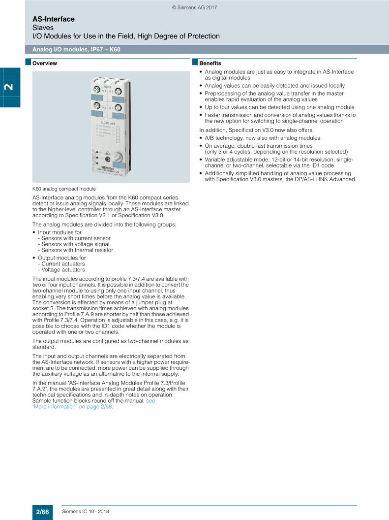
2/66 Siemens IC 10 · 2018
AS-InterfaceSlavesI/O Modules for Use in the Field, High Degree of Protection
Analog I/O modules, IP67 – K60
2
■ Overview
K60 analog compact module
AS-Interface analog modules from the K60 compact series detect or issue analog signals locally. These modules are linked to the higher-level controller through an AS-Interface master according to Specification V2.1 or Specification V3.0.
The analog modules are divided into the following groups:• Input modules for
- Sensors with current sensor- Sensors with voltage signal- Sensors with thermal resistor
• Output modules for- Current actuators- Voltage actuators
The input modules according to profile 7.3/7.4 are available with two or four input channels. It is possible in addition to convert the two-channel module to using only one input channel, thus enabling very short times before the analog value is available. The conversion is effected by means of a jumper plug at socket 3. The transmission times achieved with analog modules according to Profile 7.A.9 are shorter by half than those achieved with Profile 7.3/7.4. Operation is adjustable in this case, e.g. it is possible to choose with the ID1 code whether the module is operated with one or two channels.
The output modules are configured as two-channel modules as standard.
The input and output channels are electrically separated from the AS-Interface network. If sensors with a higher power require-ment are to be connected, more power can be supplied through the auxiliary voltage as an alternative to the internal supply.
In the manual "AS-Interface Analog Modules Profile 7.3/Profile 7.A.9", the modules are presented in great detail along with their technical specifications and in-depth notes on operation. Sample function blocks round off the manual, see "More information" on page 2/68.
■ Benefits
• Analog modules are just as easy to integrate in AS-Interface as digital modules
• Analog values can be easily detected and issued locally• Preprocessing of the analog value transfer in the master
enables rapid evaluation of the analog values• Up to four values can be detected using one analog module• Faster transmission and conversion of analog values thanks to
the new option for switching to single-channel operation
In addition, Specification V3.0 now also offers:• A/B technology, now also with analog modules• On average, double fast transmission times
(only 3 or 4 cycles, depending on the resolution selected)• Variable adjustable mode: 12-bit or 14-bit resolution, single-
channel or two-channel, selectable via the ID1 code• Additionally simplified handling of analog value processing
with Specification V3.0 masters, the DP/AS-i LINK Advanced
© Siemens AG 2017

2/67Siemens IC 10 · 2018* You can order this quantity or a multiple thereof.Illustrations are approximate
AS-InterfaceSlaves
I/O Modules for Use in the Field, High Degree of Protection
Analog I/O modules, IP67 – K60
2
■ Selection and ordering data
1) Some modules are available in the extended temperature range (from -25 to 70 °C) and for use in difficult environmental conditions (coated according to environment standard IEC 60721).
For more information, see www.siemens.com/siplus-extreme.
Version SD Article No. Priceper PU
PU(UNIT,
SET, M)
PS* PG
d
3RK1207-1BQ44-0AA3
Analog I/O modules IP67 – K60, analog profile 7.3
• Slave type: Standard• Width 60 mm• Modules supplied without mounting plateInputs Type Measuring range1 or 2 inputs (selectable using jumper plug at socket 3)
Current 4 ... 20 mA or 20 mA (selectable)1)
2 3RK1207-1BQ40-0AA3 1 1 unit 42C
Voltage 10 V or 1 ... 5 V(selectable)
2 3RK1207-2BQ40-0AA3 1 1 unit 42C
Thermal resistance Pt100 orNi100 or0 ... 600 (selectable)1)
2 3RK1207-3BQ40-0AA3 1 1 unit 42C
4 inputs Current 4 ... 20 mA or 20 mA (selectable)
2 3RK1207-1BQ44-0AA3 1 1 unit 42C
Voltage 10 V or 1 ... 5 V (selectable)
10 3RK1207-2BQ44-0AA3 1 1 unit 42C
Thermal resistance Pt100 orNi100 or0 ... 600 (selectable)
2 3RK1207-3BQ44-0AA3 1 1 unit 42C
Outputs Type Output range2 outputs Current
for 2-wire actuators
4 ... 20 mA or 20 mA or 0 ... 20 mA (selectable)1)
2 3RK1107-1BQ40-0AA3 1 1 unit 42C
Voltage for 2-wire actuators
10 V or 0 ... 10 V or 1 ... 5 V (selectable)
2 3RK1107-2BQ40-0AA3 1 1 unit 42C
3RK2207-2BQ50-0AA3
Analog I/O modules IP67 – K60, analog profile 7.A.9
• Slave type: A/B (Spec. V3.0)• Width 60 mm• Modules supplied without mounting plateInputs Type Measuring range1 or 2 inputs (vari-ably adjustable)
Current 4 ... 20 mA or 20 mA (selectable)
2 3RK2207-1BQ50-0AA3 1 1 unit 42C
Voltage 10 V or 1 ... 5 V (selectable)
2 3RK2207-2BQ50-0AA3 1 1 unit 42C
Description SIPLUS article number Corresponds to module
SIPLUS AS-Interface 2AA, IP67 6AG1107-1BQ40-7AA3 3RK1107-1BQ40-0AA3SIPLUS AS-Interface 2AI, IP67 6AG1207-1BQ40-7AA3 3RK1207-1BQ40-0AA3SIPLUS AS-Interface 2AI, IP67 6AG1207-3BQ40-7AA3 3RK1207-3BQ40-0AA3
© Siemens AG 2017

2/68 Siemens IC 10 · 2018* You can order this quantity or a multiple thereof.
Illustrations are approximate
AS-InterfaceSlavesI/O Modules for Use in the Field, High Degree of Protection
Analog I/O modules, IP67 – K60
2
■ Accessories
■ More information
Version SD Article No. Priceper PU
PU(UNIT,
SET, M)
PS* PG
d
3RK1901-0CA00
K60 mounting plates
• Wall mounting } 3RK1901-0CA00 1 1 unit 42C• Standard rail mounting } 3RK1901-0CB01 1 1 unit 42C
3RK1901-1KA00
M12 sealing caps } 3RK1901-1KA00 100 10 units 42C
3RK1902-0AR00
Sealing sets
• For K60 mounting plate and distributor• Cannot be used for K45 mounting plate• One set contains one straight and one shaped seal
2 3RK1902-0AR00 100 5 units 42D
3RK1901-1AA00
Jumper plugsFor changing over the 2-channel input modules
2 3RK1901-1AA00 1 1 unit 42C
More information
For the Manual "AS-Interface Analog Modules Profile 7.3/Profile 7.A.9", see https://support.industry.siemens.com/cs/ww/en/view/7643815
© Siemens AG 2017

2/69Siemens IC 10 · 2018
AS-InterfaceSlaves
I/O Modules for Use in the Control Cabinet
Introduction
2
■ Overview
SC17.5F, SC17.5 and SC22.5 SlimLine Compact modules
F90 module
Flat module
For AS-Interface applications inside control cabinets, there are various module series for the most diverse requirements:• SlimLine Compact – particularly slim design ideal for
space-saving use in the control cabinet• F90 module – particularly flat design for flat control boxes• Flat module – special design for integration into customer-
specific solutions
The existing SlimLine series of modules S22.5 and S45 are being replaced by the innovative new devices in the SlimLine Compact SC17.5, SC17.5F and SC22.5 series. The previous SlimLine modules are still available as replacements for existing systems.
Available versions
The following table provides an overview of the key features of the different series of control cabinet modules.
✓ Available-- Not available
Feature SlimLine Compact F90 module
Flat module
Digital I/O ✓ ✓ ✓
Analog I/O ✓ -- --Safe inputs ✓ -- --Relay outputs ✓ -- --A/B slave ✓ -- --Mounting onto TH 35 standard mounting rail according to IEC 60715
✓ ✓ --
Wall mounting using push-in lugs
✓ -- --
Integrated lugs for screw fixing
-- -- ✓
Width in mm 17.5 or 22.5 90 80
© Siemens AG 2017

2/70 Siemens IC 10 · 2018
AS-InterfaceSlavesI/O Modules for Use in the Control Cabinet
SlimLine Compact
2
■ Overview
SlimLine Compact modules
SC17.5 and SC22.5 SlimLine Compact modules with screw terminals SlimLine Compact module SC22.5 with connector with screw terminals
The AS-Interface module series for the control cabinet SlimLine Compact with degree of protection IP20 creates space in the cabinet and in distributed local control boxes. A width of just 17.5 mm or 22.5 mm ensures considerable space savings in the control cabinet.
The SlimLine Compact module series comprises not only digital and analog I/O modules but also ASIsafe modules with safe inputs. Digital outputs are available as solid-state and relay outputs.
Sensors and actuators, as well as the AS-Interface bus cable, are connected by means of removable screw or push-in spring-type terminals. Device connectors available as accessories offer the possibility of looping through the AS-Interface bus cable and the 24 V DC power supply Uaux from one module to additional modules. This significantly simplifies the wiring, as the AS-Interface bus cable and Uaux only have to be connected to one device.
All devices for the connection of 3-wire sensors offer the option of supplying the sensors either from the AS-Interface bus cable or alternatively from the 24 V DC voltage supply Uaux depending on the requirements of the particular application. A slide switch is used to make the selection. If supply via Uaux is selected, the wiring of the sensor terminals remains unchanged. This means that no external supply is required for the sensors.
All modules have LEDs on the front that provide diagnostic information and indicate the status of the module inputs and outputs. An addressing socket integrated at the front enables the module to be addressed also when it is installed. Integrated adapters permit mounting onto a standard mounting rail either directly for the module or for the device connector. Alternatively, the modules can also be screw-mounted using push-in lugs (accessories). These lugs for screw fastening must be ordered separately.
© Siemens AG 2017
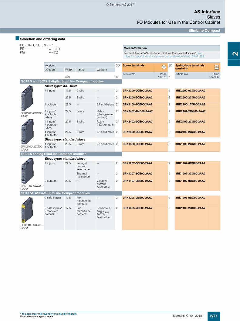
2/71Siemens IC 10 · 2018* You can order this quantity or a multiple thereof.Illustrations are approximate
AS-InterfaceSlaves
I/O Modules for Use in the Control Cabinet
SlimLine Compact
2
■ Selection and ordering data
PU (UNIT, SET, M) = 1 PS* = 1 unit PG = 42C
More information
For the Manual "AS-Interface SlimLine Compact Modules", see https://support.industry.siemens.com/cs/ww/en/view/109481489
Version SD Screw terminals SD Spring-type terminals (push-in)I/O type Width Inputs Outputs
mm dArticle No. Price
per PU dArticle No. Price
per PU
SC17.5 and SC22.5 digital SlimLine Compact modules
3RK2200-0CG00-2AA2
3RK2400-2CG00-2AA2
Slave type: A/B slave4 inputs 17.5 2-wire -- 2 3RK2200-0CE00-2AA2 2 3RK2200-0CG00-2AA2
22.5 3-wire -- 2 3RK2200-2CE00-2AA2 2 3RK2200-2CG00-2AA2
4 outputs 22.5 -- 2A solid-state 2 3RK2100-1CE00-2AA2 2 3RK2100-1CG00-2AA2
4 inputs/2 outputs, relays
22.5 3-wire Relay (change-over contact)
2 3RK2402-2ME00-2AA2 2 3RK2402-2MG00-2AA2
4 inputs/4 outputs, relays
22.5 3-wire Relay (NO contacts)
2 3RK2402-2CE00-2AA2 2 3RK2402-2CG00-2AA2
4 inputs/4 outputs
22.5 3-wire 2A solid-state 2 3RK2400-2CE00-2AA2 2 3RK2400-2CG00-2AA2
Slave type: standard slave4 inputs/4 outputs
22.5 3-wire 2A solid-state 2 3RK1400-2CE00-2AA2 2 3RK1400-2CG00-2AA2
SC22.5 analog SlimLine Compact modules
3RK1207-0CG00-2AA2
Slave type: standard slave4 inputs 22.5 Voltage/
current selectable
-- 2 3RK1207-0CE00-2AA2 2 3RK1207-0CG00-2AA2
Thermal resistance
-- 2 3RK1207-3CE00-2AA2 2 3RK1207-3CG00-2AA2
2 outputs 22.5 -- Voltage/current selectable
2 3RK1107-0BE00-2AA2 2 3RK1107-0BG00-2AA2
SC17.5F ASIsafe SlimLine Compact modules
3RK1405-0BG00-2AA2
2 safe inputs 17.5 For mechanical contacts
-- 2 3RK1205-0BE00-2AA2 2 3RK1205-0BG00-2AA2
2 safe inputs/2 standard outputs
17.5 For mechanical contacts
Solid-state, UASI/Uaux supply selectable
2 3RK1405-2BE00-2AA2 2 3RK1405-2BG00-2AA2
© Siemens AG 2017

2/72 Siemens IC 10 · 2018* You can order this quantity or a multiple thereof.
Illustrations are approximate
AS-InterfaceSlavesI/O Modules for Use in the Control Cabinet
SlimLine Compact
2
■ Accessories
1) PC labeling system for individual inscription of unit labeling plates available from: murrplastik Systemtechnik GmbH (see page 16/15).
Version SD Article No. Priceper PU
PU(UNIT,
SET, M)
PS* PG
d
3RK1901-1YA00
3RK1901-1YA10
Device connectors
For electrical connection of SlimLine Compact modules (connects AS-i bus cable and 24 V DC auxiliary power supply Uaux when using several SlimLine Compact modules)• Width 17.5 mm 2 3RK1901-1YA00 1 1 unit 42C• Width 22.5 mm 2 3RK1901-1YA10 1 1 unit 42C
3RK1901-1YA01
3RK1901-1YA11
Device termination connectors
Required for the last module in the network• Width 17.5 mm 2 3RK1901-1YA01 1 1 unit 42C• Width 22.5 mm 2 3RK1901-1YA11 1 1 unit 42C
3ZY1121-2BA00
Removable terminals Screw terminals
• Screw terminals up to 2 x 1.5 mm2 or 1 x 2.5 mm2
- 2-pole 2 3ZY1121-1BA00 1 6 units 41L- 4-pole 2 3ZY1141-1BA00 1 6 units 41L
Spring-type terminals (push-in)
• Push-In terminals up to 2 x 1.5 mm2
- 2-pole 2 3ZY1121-2BA00 1 6 units 41L- 4-pole 2 3ZY1141-2BA00 1 6 units 41L
3ZY1311-0AA00
Push-in lugs for wall mounting
Two lugs are required per device2 3ZY1311-0AA00 1 10 units 41L
3ZY1440-1AA00
Coding pins for removable terminals
For mechanical coding of the terminals2 3ZY1440-1AA00 1 12 units 41L
3RT2900-1SB20
Blank labels
Unit labeling plates1)
• 10 mm x 7 mm, titanium gray 20 3RT2900-1SB10 100 816 units 41B• 20 mm x 7 mm, titanium gray 20 3RT2900-1SB20 100 340 units 41B
3RA2908-1A
Tools for opening spring-type terminals Spring-type terminals
Screwdriver for SIRIUS devices with spring-type terminals3.0 mm x 0.5 mm, length approx. 200 mm, titanium gray/black, partially insulated
2 3RA2908-1A 1 1 unit 41B
IC01
_001
81
© Siemens AG 2017

2/73Siemens IC 10 · 2018
AS-InterfaceSlaves
I/O Modules for Use in the Control Cabinet
SlimLine Compact
2
■ More information
SlimLine modules S45 (picture on left) and S22.5 module (picture on right) with spring-type terminals
The existing SlimLine series of I/O modules for use in the control cabinet is being replaced by the new, innovative SlimLine Compact series. We recommend that these new devices are used in future.
The code conversion table indicates the best options for replacing the existing SlimLine devices with SlimLine Compact devices.
Note:
The previous SlimLine devices are still available for use as replacements in existing systems. As a result of the innovation, the new SlimLine Compact devices are not fully compatible in terms of either mechanical dimensions or electrical properties.
The code conversion table below links the existing SlimLine S22.5, S22.5F and S45 modules with the new SlimLine Compact SC17.5, SC17.5F and SC22.5 devices.
Code conversion table
S22.5, S22.5F and S45 SlimLine Comparison type: SC17.5, SC17.5F and SC22.5 SlimLine Compact
Screw terminals Spring-type terminals Version Screw terminals Spring-type terminals Version3RK1200-0CE00-0AA2 3RK1200-0CG00-0AA2 4DI, 2-wire, standard slave 3RK2200-0CE00-2AA2 3RK2200-0CG00-2AA2 4DI, 2-wire, A/B slave3RK2200-0CE02-0AA2 3RK2200-0CG02-0AA2 4DI, A/B slave 3RK2200-2CE00-2AA2 3RK2200-2CG00-2AA2 4DI, A/B slave3RK1200-0CE02-0AA2 3RK1200-0CG02-0AA2 4DI, standard slave3RK1400-0BE00-0AA2 3RK1400-0BG00-0AA2 2DI/2DQ, standard slave 3RK1400-2CE00-2AA2 3RK1400-2CG00-2AA2 4DI/4DQ, standard slave3RK1402-0BE00-0AA2 3RK1402-0BG00-0AA2 2DI/2DQ relay, standard slave 3RK2402-2ME00-2AA2 3RK2402-2MG00-2AA2 4DI/2DQ relay, A/B slave3RK1100-1CE00-0AA2 3RK1100-1CG00-0AA2 4DQ, standard slave 3RK2100-1CE00-2AA2 3RK2100-1CG00-2AA2 4DQ, A/B slave3RK2400-1CE01-0AA2 3RK2400-1CG01-0AA2 4DI/4DQ A/B slave 3RK2400-2CE00-2AA2 3RK2400-2CG00-2AA2 4DI/4DQ, A/B slave3RK2400-1FE00-0AA2 3RK2400-1FG00-0AA2 4DI/3DQ, A/B slave3RK1400-1CE00-0AA2 3RK1400-1CG00-0AA2 4DI/4DQ, 1 A solid-state,
standard slave3RK1400-2CE00-2AA2 3RK1400-2CG00-2AA2 4DI/4DQ, 2 A solid-state,
standard slave3RK1400-1CE01-0AA2 3RK1400-1CG01-0AA2 4DI/4DQ, 2 A solid-state,
standard slave3RK1402-3CE01-0AA2 3RK1402-3CG01-0AA2 4DI/4DQ
(sensor supply from Uaux), standard slave
3RK1402-3CE00-0AA2 3RK1402-3CG00-0AA2 4DI/4DQ, relay, standard slave 3RK2402-2CE00-2AA2 3RK2402-2CG00-2AA2 4DI/4DQ, relay, A/B slave3RK1205-0BE00-0AA2 3RK1205-0BG00-0AA2 2F-DI 3RK1205-0BE00-2AA2 3RK1205-0BG00-2AA2 2F-DI 3RK1405-0BE00-0AA2 3RK1405-0BG00-0AA2 2F-DI/2DQ
(outputs supplied from UASI)3RK1405-2BE00-2AA2 3RK1405-2BG00-2AA2 2F-DI/2DQ
(supply UASI/Uaux selectable)3RK1405-1BE00-0AA2 3RK1405-1BG00-0AA2 2F-DI/2DQ
(outputs supplied from Uaux)
© Siemens AG 2017
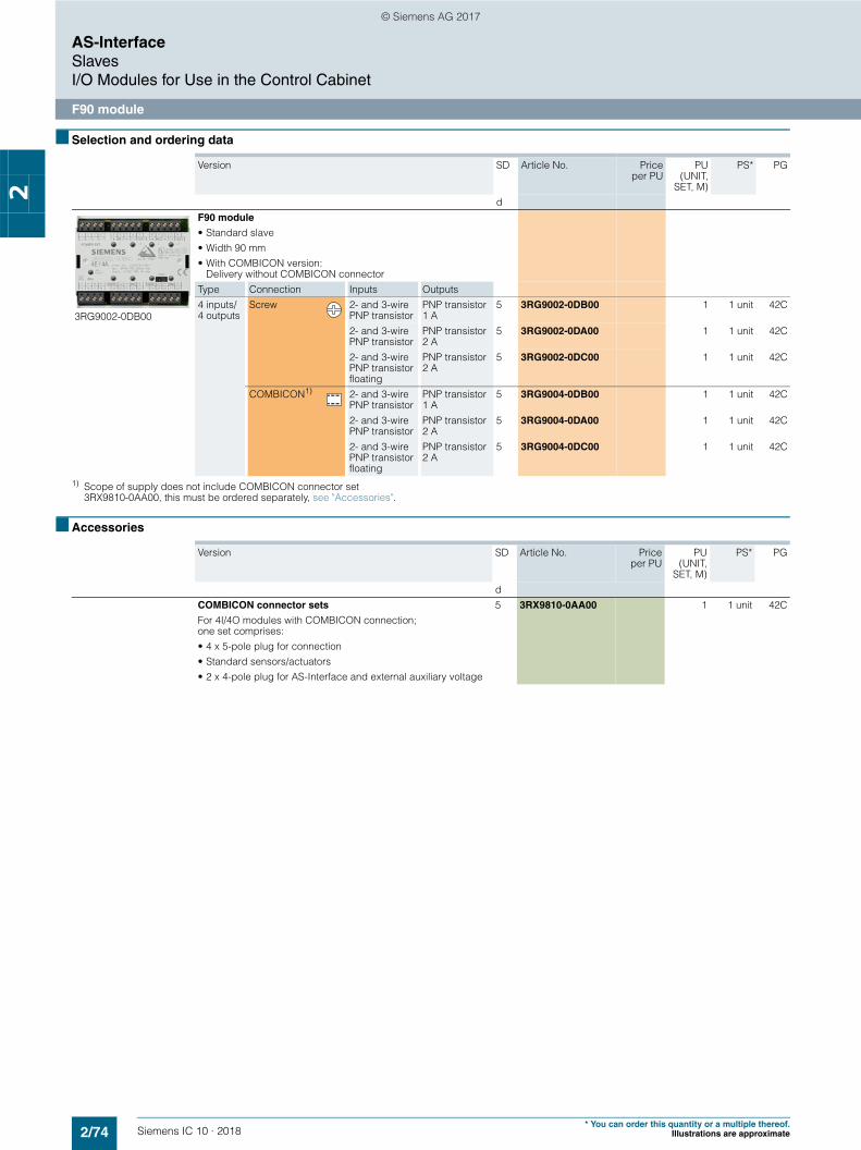
2/74 Siemens IC 10 · 2018* You can order this quantity or a multiple thereof.
Illustrations are approximate
AS-InterfaceSlavesI/O Modules for Use in the Control Cabinet
F90 module
2
■ Selection and ordering data
1) Scope of supply does not include COMBICON connector set 3RX9810-0AA00, this must be ordered separately, see "Accessories".
■ Accessories
Version SD Article No. Priceper PU
PU(UNIT,
SET, M)
PS* PG
d
3RG9002-0DB00
F90 module
• Standard slave• Width 90 mm• With COMBICON version:
Delivery without COMBICON connectorType Connection Inputs Outputs4 inputs/ 4 outputs
Screw 2- and 3-wire PNP transistor
PNP transistor 1 A
5 3RG9002-0DB00 1 1 unit 42C
2- and 3-wire PNP transistor
PNP transistor 2 A
5 3RG9002-0DA00 1 1 unit 42C
2- and 3-wire PNP transistor floating
PNP transistor 2 A
5 3RG9002-0DC00 1 1 unit 42C
COMBICON1) 2- and 3-wire PNP transistor
PNP transistor 1 A
5 3RG9004-0DB00 1 1 unit 42C
2- and 3-wire PNP transistor
PNP transistor 2 A
5 3RG9004-0DA00 1 1 unit 42C
2- and 3-wire PNP transistor floating
PNP transistor 2 A
5 3RG9004-0DC00 1 1 unit 42C
Version SD Article No. Priceper PU
PU(UNIT,
SET, M)
PS* PG
dCOMBICON connector sets
For 4I/4O modules with COMBICON connection; one set comprises:• 4 x 5-pole plug for connection• Standard sensors/actuators• 2 x 4-pole plug for AS-Interface and external auxiliary voltage
5 3RX9810-0AA00 1 1 unit 42C
© Siemens AG 2017

2/75Siemens IC 10 · 2018* You can order this quantity or a multiple thereof.Illustrations are approximate
AS-InterfaceSlaves
I/O Modules for Use in the Control Cabinet
Flat modules
2
■ Overview
Flat module 4I/4O
The flat module for the control cabinet in degree of protection IP20 has four inputs and four outputs.
The module is fitted at the front with an LED which indicates the module's status.
With the integrated lugs, the modules can be screwed on.
An integrated addressing socket enables the module to be addressed when it is installed.
Standard sensors/actuators and the AS-Interface cable can be connected using screw terminals.
■ Selection and ordering data
Version SD Screw terminals PU(UNIT,
SET, M)
PS* PG
dArticle No. Price
per PU
3RK1400-0CE00-0AA3
Flat module 4I/4O
• 4 inputs/4 outputs• 200 mA for all I/Os
2 3RK1400-0CE00-0AA3 1 1 unit 42C
© Siemens AG 2017

2/76 Siemens IC 10 · 2018* You can order this quantity or a multiple thereof.
Illustrations are approximate
AS-InterfaceSlavesModules with Special Functions
Counter modules
2
■ Overview
Counter module with spring-type terminals
The counter module is used to send hexadecimally coded count values (LSB=D0, MSB=D3) to a higher-level controller. The count value is increased by 1 for each valid count pulse at terminal 8. Beginning at 0, the module counts up to 15 and then begins again at 0. The controller adopts the current value and determines the number of pulses between two host invocations through subtraction from the previous value. The total number of count pulses is determined by adding these differences.
For the values sent to be unambiguous, no more than 15 count values are allowed between two host invocations or AS-Interface master invocations at terminal 8. The maximum permissible transmission frequency is calculated from these times:
fTRmax = 15 / Tmax
Tmax: max. possible transmission time from the slave to the host
A further condition for the maximum frequency is the required pulse shape. For the counter to accept a pulse as valid, a Low must have been applied at the input for at least 300 µs and a High for at least 1 ms.
This results in a maximum frequency of fZmax = 1 / 1.3 ms = 769 Hz independently of the control system (see figure below).
Maximum frequency for the counter module
If the time criterion stipulated in the figure is violated, the count value is rejected.
The counter is active only for the reset parameter P2 (default). The counter is deleted when P2 is set, and the incoming count pulses are not registered until after P2 is reset again.
Note:
A customized function block is necessary or must be programmed.
Counter module connection options
■ Selection and ordering data
UIN1
≥ 1 ms ≥ 300 s t
NSA0_00084
Terminal 9: Sensor supply -Terminal 8: Counter inputTerminal 7: Sensor supply +
Terminal 6: UnusedTerminal 5: Bus connection ASi -Terminal 4: Bus connection ASi +
+ -IN1
ASi-ASi+
ADDR
ASi
IN1
NS
A0_
0008
5
Version SD Article No. Priceper PU
PU(UNIT,
SET, M)
PS* PG
d
3RK1200-0CE03-0AA2
3RK1200-0CG03-0AA2
Counter modules
Width 22.5 mm• With screw terminals 10 3RK1200-0CE03-0AA2 1 1 unit 42C
• With spring-type terminals 10 3RK1200-0CG03-0AA2 1 1 unit 42C
© Siemens AG 2017

2/77Siemens IC 10 · 2018* You can order this quantity or a multiple thereof.Illustrations are approximate
AS-InterfaceSlaves
Modules with Special Functions
Ground-fault detection modules
2
■ Overview
Ground-fault detection module
"Ground faults in any control circuit must not lead to unintentional starting or potentially hazardous movements or prevent the machine from stopping." (IEC 60204-1/VDE 0113-1).
The AS-Interface ground-fault detection module is used to meet these requirements. Using this module from the SlimLine series, ground faults in AS-Interface systems can be reliably detected and reported.
The following ground faults are detected:• Ground fault from AS-i "+"• Ground fault from AS-i "-"• Ground fault from sensors and actuators that are supplied
from the AS-Interface voltage.
Note:
Not suitable for AS-i Power24V.
■ Selection and ordering data
Version SD Article No. Priceper PU
PU(UNIT,
SET, M)
PS* PG
d
3RK1408-8KE00-0AA2
Ground-fault detection modules
Width 22.5 mm• With screw terminals 5 3RK1408-8KE00-0AA2 1 1 unit 42C
• With spring-type terminals 5 3RK1408-8KG00-0AA2 1 1 unit 42C
© Siemens AG 2017

2/78 Siemens IC 10 · 2018* You can order this quantity or a multiple thereof.
Illustrations are approximate
AS-InterfaceSlavesModules with Special Functions
Overvoltage protection module
2
■ Overview
AS-Interface overvoltage protection module
The AS-Interface overvoltage protection module (protection module) protects downstream AS-Interface devices or individual sections in AS-i networks from conducted overvoltages which can be caused by switching operations and remote lightning strikes. The location of the protection module forms the transition from zone 1 to 2/3 within the lightning protection zone concept. Direct lightning strikes must be coped with using additional protective measures at the transitions from lightning protection zone 0A to 1.
With the AS-Interface overvoltage protection module, it is now also possible to integrate AS-Interface in the overall overvoltage protection concept of a plant or machine.
The module has the same design and degree of protection (IP67) as the AS-Interface K45 compact modules. It is a passive module and as such does not need its own address on the AS-Interface network. The module can be used to protect the AS-Interface cable and the cable for the auxiliary voltage from overvoltage. Overvoltages are discharged through a ground cable with a green/yellow oil-proof outer sheath. This cable is fixed in the module and must be connected with low resistance to the system's ground.
Rated discharge current Isn
The rated discharge current is the peak value of a surge current of the form 8/20 s (microseconds), for which the protection module is designed in accordance with a specified test program. With an 8/20 waveform, 100 % of the value is achieved after 8 s and 50 % after 20 s.
Protection level Up
The protection level of a protection module is the highest momentary value of the voltage at the terminals, established in individual tests and characterizes the capability of a protection module to limit overvoltages to a residual level.
Configuration guidelines
The grounding of protection modules and the units to be protected must be effected through a shared grounding point.
If insulated devices are protected, their mounts must be included in the grounding points.
Sample application
■ Selection and ordering data
AS-Inter-face
AS-Inter-face
NSA0_00093a
OVP = Overvoltage protection
Mounting plate
Application
Device withground terminal
Device without ground terminal→ Grounding of the mounting plateApplication
OVP
Version SD Article No. Priceper PU
PU(UNIT,
SET, M)
PS* PG
dAS-Interface overvoltage protection module 5 3RK1901-1GA01 1 1 unit 42CDelivery includes mounting plate (for wall and standard rail mounting)
NSA0_00092b
AS-Inter-faceA B
AS-Inter-face
AS-Inter-face
AS-Inter-face
OVP = Overvoltage protection
OVPOVP
Protected range
Zone 1 Zone 1Zone 2
Protection approx. 5 m to the right
Equipotential bonding(system earth)Protection approx. 0.5 m to the left
© Siemens AG 2017

2/79Siemens IC 10 · 2018
AS-InterfacePower Supply Units and Data Decoupling Modules
AS-Interface power supply units
2
* You can order this quantity or a multiple thereof.Illustrations are approximate
■ Overview
AS-Interface power supply unit for 3 A
AS-Interface power supply units feed 30 V DC into the AS-Interface cable and supply the AS-Interface components. They include power-optimized data decoupling for the separa-tion of communication signals and control supply voltage. As the result, AS-Interface is able to convey both data and power along a single line. The power supply units are resistant to overload and short circuits.
Dimensions
AS-Interface power supply units have compact dimensions in widths of 50/70/120 mm. No distances from other devices need to be observed when mounting the power supply units.
Features• Higher rating: The power supply units deliver currents of
2.6 to 8 A.• Integrated data decoupling: As the result, AS-Interface is able
to convey both data and power along a single line.• Integrated ground-fault detection: The power supply units
perform the reliable detection and signaling of ground faults according to IEC 60204-1. The AS-Interface voltage can be disconnected automatically in the event of a ground fault.
• Integrated overload detection: An output overload is detected and reported over a diagnostics LED.
• Diagnostics memory: Any ground faults or overloads on the output side are stored in a diagnostics memory until the device is RESET.
• Remote RESET and remote signaling: Using relay contacts, a ground fault can be signaled and evaluated by a central controller and/or indicator light.
• Diagnostics LEDs: Three different LEDs indicate the status of the AS-Interface power supply locally at the power supply unit.
• Ultra-wide input range/two-phase connection: The ultra-wide input range of 120 to 500 V of the 8 A version means that the supply units can be used in virtually any network worldwide. In addition, this version dispenses with the need for an N conductor as the device can be connected directly between 2 phases of a network.
• Operation with 24 V DC: The 3 A power supply unit is also available as a version with a 24 V DC input. This power supply unit is suitable for use in battery-powered systems or in systems with UPS (uninterruptible power supply).
• Removable terminal blocks with spring-type connections: For easy exchanging of devices, each power supply unit has three removable terminal blocks: for the input side, for the output side and for Signal/RESET connections.
■ Benefits
• Complete solution for supplying AS-Interface networks while making full use of the maximum possible cable length per AS-i segment
• Only AS-i masters and AS-i slaves need to be connected to the AS-Interface cable in order to operate AS-Interface
• Compact, space-saving dimensions• Reliable power supply even for large numbers of AS-Interface
modules with a high power requirement• Integrated ground-fault and overload detection saves the
need for additional components and enhances safety• Fast fault detection and reduced downtimes thanks to
diagnostics memory, remote signaling and remote RESET
• Reduced downtimes as the result of removable terminal blocks which enable the fast exchanging of devices
• Ultra-wide input range of the 8 A version permits single-phase and two-phase operation and removes the need for an N conductor
• Can be used world-wide thanks to, for example, UL/CSA approval (UL 508)
• With the 2.6 A version, the output power is restricted to max. 100 W for use in Class 2 circuits in accordance with NEC (National Electrical Code)
■ Selection and ordering data
Version SD Spring-type terminals PU (UNIT,SET, M)
PS* PG
dArticle No. Price
per PU
3RX9501-0BA00
3RX9503-0BA00
AS-Interface power supply units, IP20
• AS-i single output 30 V DC• With integrated ground-fault detection• 2.6 A version with output power restricted to max. 100 W
(for Class 2 circuits in accordance with NEC)• Dimensions:
Width: 50 mm (2.6 A/3 A), 70 mm (5 A), 120 mm (8 A); Height: 125 mm; Depth: 125 mm
Output current Input voltage2.6 A/max. 100 W 120/230 V AC (selectable) } 3RX9501-2BA00 1 1 unit 42C3 A 120/230 V AC (selectable) } 3RX9501-0BA00 1 1 unit 42C3 A 24 V DC } 3RX9501-1BA00 1 1 unit 42C5 A 120/230 V AC (selectable) } 3RX9502-0BA00 1 1 unit 42C8 A 120/230 ... 500 V AC
(selectable)} 3RX9503-0BA00 1 1 unit 42C
© Siemens AG 2017

2/80 Siemens IC 10 · 2018
AS-InterfacePower Supply Units and Data Decoupling Modules
30 V power supply units
2
■ Overview
PSN130S 30 V power supply units for 3 A, 4 A and 8 A
The PSN130S 30 V power supplies feed 30 V DC into the AS-Interface cable and supply the AS-Interface components, but do not include data decoupling. Data decoupling modules are needed in addition therefore to separate communication signals and control supply voltage, see page 2/82 or 2/84.
The power supply units are resistant to overload and short circuits.
Dimensions
The 30 V power supply units have compact dimensions with widths of 50 and 70 mm. No distances from other devices need to be observed when mounting the power supply units.
Features• Primary clocked power supply units for connection to a single-
phase AC network• Power for currents of 3 A, 4 A and 8 A• The output voltage is floating, and resistant to short-circuits
and no-load operation. If there is an overload, the output voltage is reduced or cut-off. After a short-circuit or overload, the devices start up again automatically.
• In the event of a device fault, the output voltage will be limited to max. 37 V.
• Modular installation devices in degree of protection IP20 and safety class I
• Diagnostics: With an output voltage > 26.5 V DC, the green LED (30V O.K.) is lit and the signaling contact 13-14 is closed.
■ Benefits
• Low-cost alternative solution for supplying AS-Interface networks while making full use of the maximum possible cable length per AS-i segment
• Cost advantage particularly for multiple networks• Compact, space-saving dimensions
• Reliable power supply even for large numbers of AS-Interface modules with a high power requirement
• Can be used world-wide thanks to, for example, UL/CSA approval (UL 508)
■ Application
Configuration examples of AS-Interface networks with a 30 V power supply unit
Configuration of AS-Interface multiple networks with one PSN130S 30 V power supply unit (examples with schematic representation): Left: Double network based on the S22.5 double data decoupling module and IE/AS-i Link PN IO double master Right: Triple network based on the SIMATIC S7-1200 with DCM 1271 data decoupling modules and CM 1243-2 communication processors
S7-1200 and CM 1243-2 multiple AS-i master with DCM 1271 data decoupling module
PSN130S30 V power supply unit
AS-Interface
AS-Interface
AS-Interface
IC01
_002
22
IE/AS-i Link PN IO double master and double data decoupling module
PSN130S30 V power supply unit AS-Interface
PROFINET
AS-Interface
IC01
_002
21b
© Siemens AG 2017

2/81Siemens IC 10 · 2018
AS-InterfacePower Supply Units and Data Decoupling Modules
30 V power supply units
2
* You can order this quantity or a multiple thereof.Illustrations are approximate
■ Technical specifications
■ Selection and ordering data
■ More information
Version 3 A 4 A 8 A
Input data
• Input voltage, rated value Ue V AC 120/230 V, single-phase, automatic selection
• Range of input voltage V AC 85 ... 132/174 ... 264• Mains frequency Hz 50/60 • Power consumption at full load, typ. W 103 139 270Output data
• Output voltage, rated value Ua V DC 30• Residual ripple mVpp < 150 • Output current, rated value
at -20 ... +60 °CA 3 4 8
• Max. output current at +60 ... +70 °C
A 3 3 4
Degree of efficiency in rated conditions
• Degree of efficiency % 87 88 90• Power loss, typ. W 12 17 25Protection and monitoring
• Output overvoltage protection V < 37• Current limit, typ. A 4 5.5 11Safety
• Primary/secondary electrical isolation
Output voltage PELV/SELV according to IEC 60950 and EN 50178
• Protection class I• Degree of protection IP20
Approvals
• UL UL 508/CSA 22.2• Pollution degree IEC 60950• Overvoltage category and
electrical separation EN 50178 and IEC 61558
EMC
• Emitted interference (class B) IEC 61000-6-3• Line harmonics limit IEC 61000-3-2• Interference immunity IEC 61000-6-2Operating data
Ambient temperature• Operation °C -20 ... +70• Transport/storage °C -40 ... +85Pollution degree 2Humidity class Climate class according to
DIN 50010, relative air humid-ity max. 100%, without condensation
Dimensions and weight
• Width mm 50 50 70• Height x depth mm 125 x 126.5• Weight kg 0.4 0.4 0.7
Version 3 A 4 A 8 A
Version SD Screw terminals PU(UNIT,
SET, M)
PS* PG
dArticle No. Price
per PU
3RX9511-0AA00
3RX9512-0AA00
3RX9513-0AA00
PSN130S 30 V DC power supply unit (without AS-i data decoupling)
• Output voltage 30 V DC• Dimensions:
Width: 50 mm (3 A/4 A); 70 mm (8 A); Height: 125 mm; Depth: 126.5 mm
Output current Input voltage3 A 120/230 V AC
(automatic selection)} 3RX9511-0AA00 1 1 unit 42C
4 A 120/230 V AC (automatic selection)
} 3RX9512-0AA00 1 1 unit 42C
8 A 120/230 V AC (automatic selection)
} 3RX9513-0AA00 1 1 unit 42C
More information
For operating instructions and other technical information, see https://support.industry.siemens.com/cs/ww/en/view/64364000
© Siemens AG 2017

2/82 Siemens IC 10 · 2018
AS-InterfacePower Supply Units and Data Decoupling Modules
S22.5 data decoupling modules
2
■ Overview
AS-Interface S22.5 double data decoupling module: Screw terminal version (picture left), Spring-type terminal version (picture right)
With the aid of the S22.5 data decoupling module, the AS-Interface network can also be supplied with 24 V DC or 30 V DC from a standard power supply unit and the transmission of data and power can be realized along one cable.
The combination of data decoupling modules and standard power supply units is therefore a cost-efficient alternative to the service-proven AS-Interface power supply units.
The quality of the data signals and the reliable operation of the AS-i network are not negatively affected as the result.
Features of the S22.5 data decoupling unit• Degree of protection IP20• Narrow design: 22.5 mm wide• Version with screw or spring-type terminals• Versions for single and double data decoupling• Supply of several AS-i networks with a single power supply
unit• Operation with 24 V DC or 30 V DC, grounded or
non-grounded• Adjustable current limiting up to 2 x 4 A• Integrated ground-fault detection with fault storage• Diagnostics LEDs and signaling contacts• RESET by button or remote RESET
Ground-fault detection
The integrated ground-fault detection works with a grounded and non-grounded supply: The connection of negative pole and ground (upstream from the data decoupling module) customary with 24 V DC power supplies is permitted. A ground fault to the negative or positive pole on the AS-Interface network (down-stream from the data decoupling module) is detected and stored as a fault and will be signaled using LEDs and a relay contact.
■ Benefits
• Compatible expansion of the AS-Interface system• An existing standard power supply unit with 24 V DC or
30 V DC can be used for supplying AS-i networks• The AS-Interface system can also be used in tightly budgeted
applications because no AS-Interface power supply unit needs to be purchased
• Applications benefit in addition from the advantages of a mod-ern bus system: - High level of standardization- Additional diagnostics and maintenance information- Faster commissioning
• Easy and cost-efficient design of single and multiple networks is possible
■ Application
The AS-Interface data decoupling module is designed for AS-Interface networks with 30 V or 24 V supply (AS-i Power24V).
Operation of an AS-i network with the data decoupling module and a 30 V standard power supply unit is technically equivalent to the use of an AS-Interface power supply unit and offers the service-proven features of AS-Interface for all applications.
AS-Interface Power24V uses a 24 V power supply unit in conjunction with a data decoupling module and is particularly suitable for: • Compact machines using AS-Interface input/output modules • Applications in the control cabinet for AS-Interface integration
of SIRIUS 3RT2 contactors using 3RA27 function modules
When using the double data decoupling module or other data decoupling units, several AS-Interface networks can be oper-ated with a single power supply unit. This results in an additional cost advantage.
Note:
The power supply units must comply with the PELV (Protective Extra Low Voltage) or SELV (Safety Extra Low Voltage) stan-dards, have a residual ripple of < 250 mVpp, and in the event of a fault must limit the output voltage to a maximum of 40 V. We recommend SITOP power supplies (see page 15/1 onwards) or PSN130S 30 V power supplies (see page 2/80).
Note on AS-i Power24V:
The length of an AS-i Power24V network is restricted to 50 m in order to limit the voltage drop along the cable.
AS-i masters, AS-i slaves and the sensors and actuators sup-plied through the AS-i cable must be designed for the reduced voltage. Sensors and actuators for the standard voltage range of 10 to 30 V can be supplied with sufficient voltage.
Please also observe the requirements specified in "Extension of AS-i Power24V" for implementation of AS-i Power24V, see page 2/21.
For more information on AS-i Power24V, see System Manual "AS-Interface", https://support.industry.siemens.com/cs/ww/en/view/26250840.
© Siemens AG 2017

2/83Siemens IC 10 · 2018
AS-InterfacePower Supply Units and Data Decoupling Modules
S22.5 data decoupling modules
2
* You can order this quantity or a multiple thereof.Illustrations are approximate
Construction of an AS-i Power24V network with an AS-Interface S22.5 data decoupling module
Left: single network, right: Multiple network
■ Selection and ordering data
Version SD Article No. Priceper PU
PU(UNIT,
SET, M)
PS* PG
d
3RK1901-1DE12-1AA0
S22.5 data decoupling modules
With screw terminals, removable terminals, width 22.5 mm, height 101 mm, depth 115 mm
Screw terminals
• Single data decoupling module, 1 x 4 A } 3RK1901-1DE12-1AA0 1 1 unit 42C• Double data decoupling module, 2 x 4 A } 3RK1901-1DE22-1AA0 1 1 unit 42C
3RK1901-1DG12-1AA0
S22.5 data decoupling modules
With spring-type terminals, removable terminals, width 22.5 mm, height 105 mm, depth 115 mm
Spring-type terminals
• Single data decoupling module, 1 x 4 A } 3RK1901-1DG12-1AA0 1 1 unit 42C• Double data decoupling module, 2 x 4 A } 3RK1901-1DG22-1AA0 1 1 unit 42C
I/O modules
I/O modules
Up to 50 mDouble data
decoupling module
S7-300 with CP 343-2 / CP 343-2Pand 24 V standard power supply unit
AS-Interface
AS-Interface
PROFINET
NS
B0_
0219
2a
I/O modules
Up to 50 mSingledata
decou-pling unit
S7-300 with CP 343-2 / CP 343-2Pand 24 V standard power supply unit
AS-Interface
PROFINET
NS
B0_
0219
1a
© Siemens AG 2017

2/84 Siemens IC 10 · 2018
AS-InterfacePower Supply Units and Data Decoupling ModulesData Decoupling Modules for S7-1200
DCM 1271 data decoupling module
2
■ Overview
DCM 1271 data decoupling module for SIMATIC S7-1200
With the aid of the DCM 1271 data decoupling module, the AS-Interface network can also be supplied with 24 V DC or 30 V DC from a standard power supply unit and the transmission of data and power can be realized along one cable.
The DCM 1271 data decoupling module has the same enclosure design as the S7-1200 module and is therefore ideal for combining with the CM 1243-2 AS-i master.
The DCM 1271 data decoupling module has no connection to the backplane bus of the SIMATIC S7-1200 and is not counted as a communication module when calculating the maximum configuration.
Features of the DCM 1271 data decoupling module• Design: S7-1200, 30 mm wide, degree of protection IP20• Detachable terminals (scope of supply)• Single data decoupling• Supply of several AS-i networks with a single power supply
unit• Operation with 24 V DC or 30 V DC, grounded or
non-grounded• Current limiting at 4 A• Integrated ground-fault detection • Diagnostics LEDs for ground faults and overloads• Signaling contacts for ground-fault detection
Ground-fault detection
The integrated ground-fault detection works with a grounded and non-grounded supply: The connection of negative pole and ground (upstream from the data decoupling module) customary with 24 V DC power supplies is permitted. A ground fault to the negative or positive pole on the AS-Interface network (behind the data decoupling module) is identified and signaled via LED and a transistor output.
■ Benefits
• An existing standard power supply unit with 24 V DC or 30 V DC can be used for supplying AS-i networks
• The AS-Interface system can also be used in tightly budgeted applications because no AS-Interface power supply unit needs to be purchased
• Applications benefit in addition from the advantages of a modern bus system:- High level of standardization- Additional diagnostics and maintenance information- Faster commissioning
■ Application
The AS-Interface data decoupling module is designed for AS-Interface networks with 30 V or 24 V supply (AS-i Power24V).
Operation of an AS-i network with the data decoupling module and a 30 V standard power supply unit is technically equivalent to the use of an AS-Interface power supply unit and offers the service-proven features of AS-Interface for all applications.
AS-i Power24V uses a 24 V power supply unit in conjunction with a data decoupling module and is particularly suitable for• Compact machines using AS-Interface input/output modules• Applications in the control cabinet for AS-Interface integration
of SIRIUS 3RT2 contactors using 3RA27 function modules
Note:
The power supply units must comply with the PELV (Protective Extra Low Voltage) or SELV (Safety Extra Low Voltage) standards, have a residual ripple of < 250 mVpp, and in the event of a fault must limit the output voltage to a maximum of 40 V. We recommend SITOP power supplies (see page 15/1 onwards) or PSN130S 30 V power supplies (see page 2/80).
Note on AS-i Power24V:
The length of an AS-i Power24V network is restricted to 50 m in order to limit the voltage drop along the cable.
AS-i masters, AS-i slaves and the sensors and actuators supplied through the AS-i cable must be designed for the reduced voltage. Sensors and actuators for the standard voltage range of 10 to 30 V can be supplied with sufficient voltage.
Please also observe the requirements specified in "Extension of AS-i Power24V" for implementation of AS-i Power24V, see page 2/21.
For more information on AS-i Power24V, see System Manual "AS-Interface", https://support.industry.siemens.com/cs/ww/en/view/26250840.
Configuration of an AS-i Power24V network with DCM 1271 AS-Interface data decoupling unit
I/O modules
Up to 50 m
S7-1200 with DCM 1271, CM 1243-2and 24 V standard power supply unit
AS-Interface
PROFINET
NS
B0_
0224
5a
© Siemens AG 2017

2/85Siemens IC 10 · 2018
AS-InterfacePower Supply Units and Data Decoupling Modules
Data Decoupling Modules for S7-1200
DCM 1271 data decoupling module
2
* You can order this quantity or a multiple thereof.Illustrations are approximate
■ Selection and ordering data
■ Accessories
■ More information
Version SD Screw terminals PU(UNIT,
SET, M)
PS* PG
dArticle No. Price
per PU
3RK7271-1AA30-0AA0
DCM 1271 data decoupling module
• With screw terminals, removable terminals (included in the scope of supply)
• Dimensions (W H D/mm): 30 100 75
2 3RK7271-1AA30-0AA0 1 1 unit 42C
Version SD Screw terminals PU(UNIT,
SET, M)
PS* PG
dArticle No. Price
per PUScrew terminals (replacement)
• 5-pin for AS-i master CM 1243-2 and AS-i DCM 1271 data decoupling module
5 3RK1901-3MA00 1 1 unit 42C
• 3-pin for AS-i DCM 1271 data decoupling module for connecting the power supply unit
5 3RK1901-3MB00 1 1 unit 42C
3RK7243-2AA30-0XB0
CM 1243-2 communication module 2 3RK7243-2AA30-0XB0 1 1 unit 42C• AS-Interface masters for SIMATIC S7-1200• Corresponds to AS-Interface Specification V3.0• With screw terminals, removable terminals
(included in the scope of supply)• Dimensions (W H D/mm): 30 100 75see also from page 2/32 onwards
More information
More information on AS-i Power24V, see System Manual "AS-Interface", https://support.industry.siemens.com/cs/ww/en/view/26250840
Manual "AS-i Master CM 1234-2 and AS-i Data Decoupling Unit DCM 1271 for SIMATIC S7-1200", seehttps://support.industry.siemens.com/cs/ww/en/view/57358958
© Siemens AG 2017

2/86 Siemens IC 10 · 2018* You can order this quantity or a multiple thereof.
Illustrations are approximate
AS-InterfaceTransmission Media
AS-Interface shaped cable
2
■ Overview
AS-Interface shaped cable
The actuator-sensor interface – the networking system used for the lowest field area – is characterized by very easy mounting and installation. A new connection method was developed specially for AS-Interface.
The stations are connected using the AS-Interface cable. This two-wire AS-Interface shaped cable has a trapezoidal shape, thus ruling out polarity reversal.
Connection is effected by the insulation piercing method. In other words, male contacts pierce the shaped AS-Interface cable and make reliable contact with the two wires. Cutting to length and stripping are superfluous. Consequently, AS-Interface stations (e.g. I/O modules, intelligent devices) can be connected in the shortest possible time and exchanging devices is quick.
To enable use in the most varied ambient conditions (e.g. in an oily environment), the AS-Interface cable is available in different materials (rubber, TPE, PUR).
For special applications it is also possible to use an unshielded standard round cable H05VV-F 2 x 1.5 mm² according to AS-i Specification. With AS-Interface, data and energy for the sensors (e.g. proximity switches) and actuators (e.g. indicator lights) are transmitted over the yellow AS-Interface cable.
The black AS-Interface cable must be used for actuators with a 24 V DC supply (e.g. solenoid valves) and a high power requirement.
Suitable for operation in tow chains
The use of the AS-Interface shaped cables with TPE and PUR outer sheath was checked in a tow chain test with the following conditions:
After termination of the 10 million cycles only slight wear was visible due to the lugs of the tow chain. No damage to the cores and core insulation could be detected.
Note:
When using a tow chain, the cables must be installed in such a way that they are not subject to tensile forces. On no account may the cables be twisted, but they must be routed flat through the tow chain.
■ Selection and ordering data
Chain length m 6Travel m 10Bending radius mm 75Travel speed m/s 4Acceleration m/s2 4Number of cycles 10 millionDuration of test approx. 3 years
(11 000 cycles per day)
Version SD Article No. Priceper PU
PU(UNIT,
SET, M)
PS* PG
d
3RX90..-0AA00
AS-Interface shaped cables
Material Color QuantityRubber Yellow (AS-Interface) 100 m roll 2 3RX9010-0AA00 1 1 unit 42C
Yellow (AS-Interface) 1 km drum 5 3RX9012-0AA00 1 1 unit 42CBlack (24 V DC) 100 m roll 2 3RX9020-0AA00 1 1 unit 42CBlack (24 V DC) 1 km drum 5 3RX9022-0AA00 1 1 unit 42C
TPE Yellow (AS-Interface) 100 m roll 2 3RX9013-0AA00 1 1 unit 42CYellow (AS-Interface) 1 km drum 5 3RX9014-0AA00 1 1 unit 42CBlack (24 V DC) 100 m roll 2 3RX9023-0AA00 1 1 unit 42CBlack (24 V DC) 1 km drum 5 3RX9024-0AA00 1 1 unit 42C
TPE special version according to UL Class 2
Yellow (AS-Interface) 100 m roll 5 3RX9017-0AA00 1 1 unit 42CBlack (24 V DC) 100 m roll 5 3RX9027-0AA00 1 1 unit 42C
PUR Yellow (AS-Interface) 100 m roll 2 3RX9015-0AA00 1 1 unit 42CYellow (AS-Interface) 1 km drum 5 3RX9016-0AA00 1 1 unit 42CBlack (24 V DC) 100 m roll 2 3RX9025-0AA00 1 1 unit 42CBlack (24 V DC) 1 km drum 5 3RX9026-0AA00 1 1 unit 42C
© Siemens AG 2017

2/87Siemens IC 10 · 2018
AS-InterfaceSystem Components and Accessories
Repeaters
2
* You can order this quantity or a multiple thereof.Illustrations are approximate
■ Overview
AS-Interface repeater
The AS-Interface repeater is used to extend the AS-Interface cable.
• In its basic version, an AS-i network comprises one segment with a maximum cable length of 100 m. An extension plug (see page 2/88) can be used to increase the cable length for a segment to a maximum of 200 m
• If this is insufficient, however, you can use one or more repeaters
• A repeater adds an extra segment to an existing segment. The extra segment can have a cable length of up to 100 m (without extension plug) or up to 200 m (with an extension plug in the extra segment)
• Each segment requires a separate AS-i power supply unit• Electrical separation of the two AS-Interface shaped cable
lines• Slaves can be used on both sides of the repeater• The additional power supply can increase the current infeed
for slaves/sensors and lower the voltage drop on the AS-i cable
• Separate display of the correct AS-Interface voltage for each segment
• Installed in K45 module enclosure IP67 with mounting plate• Easy mounting
■ Benefits
• More possibilities of use and greater freedom for plant planning through extension of the AS-Interface network
• Reduced downtime and servicing times in the event of a fault thanks to separate display of the correct AS-Interface voltage for each side
Design of an AS-Interface network with repeaters• Parallel switching of several repeaters possible
(star configuration)• Combination of series and parallel switching possible
The following conditions apply: • When used without an extension plug no more than two
repeaters are permitted between AS-i master and slave (repeaters connected in series)
• When used with an extension plug no more than one repeater is permitted between AS-i master and slave
In safety-related applications the following also applies: • When used without an extension plug, no more than two
repeaters are permitted between evaluation unit (e.g. MSS ASIsafe Modular Safety System, F-CM AS-i Safety ST for ET 200SP) and ASIsafe input slave or safe output module.
• When used with an extension plug, no more than one repeater is permitted between the evaluation unit (e.g. MSS ASIsafe Modular Safety System, F-CM AS-i Safety ST for ET 200SP) and ASIsafe input slave or safe output module.
Design of an example AS-Interface network with repeaters (without extension plug)
Note:
The AS-Interface repeater is not suitable for AS-i Power24V networks. It is recommended for use in AS-Interface networks with AS-Interface power supply units (e.g. 3RX9501-0BA00).
■ Application
The repeater is used to extend the AS-Interface network. In this case there are AS-Interface slave and one AS-Interface power supply unit on each side of the repeater.
In the case of a line topology with two repeaters and three extension plugs, the maximum possible size of the AS-Interface network is 600 m, see example configuration with extension plug on page 2/88.
■ Selection and ordering data
Power supply Power supply
Power supply
Power supply
Repeater
Repeater Repeater
S
S S S S
S
M
Master
SlaveS
M
AS-Interface
100 m 100 m 100 m
G_I
K10
_XX
_200
11a
Version SD Article No. Priceper PU
PU(UNIT,
SET, M)
PS* PG
d
6GK1210-0SA01
Repeaters for AS-Interface 5 6GK1210-0SA01 1 1 unit 42CFor cable extension, scope of supply includes mounting plate (for wall and standard rail mounting)
© Siemens AG 2017

2/88 Siemens IC 10 · 2018* You can order this quantity or a multiple thereof.
Illustrations are approximate
AS-InterfaceSystem Components and Accessories
Extension plugs
2
■ Overview
AS-Interface extension plugs compact
With the extension plug it is possible to double the cable length possible in an AS-Interface segment from 100 to 200 m.
Only one power supply unit is needed to supply power to the slaves on the up to 200 m long segment.
The extension plug compact can be installed directly onto an AS-i shaped cable. A separate M12 feeder, as was required for earlier extension plug versions, is no longer required with extension plug compact.
Design of an AS-Interface segment with an extension plug
To construct an AS-Interface segment with a cable length of more than 100 m and up to a maximum of 200 m, the extension plug is installed in a radius of around ± 10 m at the point of the network that is furthest from the power supply unit. The extension plug is not allowed to be used in AS-Interface networks smaller than 100 m. As with all AS-Interface networks, any network structure (line, tree, star) is possible when using the extension plug. Only one extension plug is required per 200 m segment even with a tree or star structure.
Note:
The AS-i bus cable must not terminate in the extension plug compact. The AS-Interface shaped cable can be terminated by means of a cable terminating piece to provide degree of protection IP67 where required, see"Miscellaneous accessories" on page 2/96.
The AS-Interface extension plug is not suitable for AS-i Power24V networks.
Maximum network size with repeaters and extension plug (master at center of network)
■ Selection and ordering data
■ Accessories
Version SD Article No. Priceper PU
PU(UNIT,
SET, M)
PS* PG
d
3RK1901-1MX02
AS-Interface Extension Plug Compact
• Doubling of the cable length to 200 m per AS-Interface segment
• With direct connection to AS-Interface shaped cable
2 3RK1901-1MX02 1 1 unit 42C
Version SD Article No. Priceper PU
PU(UNIT,
SET, M)
PS* PG
d
3RK1901-1MN00
Cable terminating piece
For sealing of open cable ends (shaped AS-Interface cable) in IP67
} 3RK1901-1MN00 1 10 units 42C
200 m
600 m
200 m 200 m
Repeater
Master
Slave
Powersupply
Slave Slave Slave Slave Slave
Powersupply
Powersupply
RepeaterExtensionPlug
ExtensionPlug
ExtensionPlug
NS
A0_
0037
1d
AS-Interface
© Siemens AG 2017

2/89Siemens IC 10 · 2018
AS-InterfaceSystem Components and Accessories
Addressing units
2
* You can order this quantity or a multiple thereof.Illustrations are approximate
■ Overview
The innovated addressing unit for AS-Interface of the AS-i Specification V3.0
The addressing unit is used to assign an address during commissioning to each AS-Interface slave. The device detects a connected slave module or a complete AS-i network and displays the found module in the LCD display. Each address can be individually set using the Up/Down keys. By turning the rotary switch, further commissioning functions are selected intuitively. The innovative device has been adapted to the current AS-i Specification V3.0 and can now also handle the I/O data of the latest slaves.
Functionality• Reading out and adjusting the slave address 0 to 31 or
1A to 31A, 1B to 31B, with automatic addressing aid and prevention of double addresses
• Reading out the slave profile (IO, ID, ID2)• Reading out and adjusting the ID1 code• Input/output test when commissioning the slaves: Read input
signals and write outputs with all digital and analog slaves according to AS-Interface Specification V3.0, including safe input slaves and complex CTT2 slaves
• Measuring the voltage on the AS-Interface cable (measuring range from 2 to 35 V)
• Display of the operational current in case of direct connection of an AS-i slave (measuring range from 0 to 150 mA)
• Storage of complete network configurations (profiles of all slaves) to simplify the addressing
• Adjusting the slave parameters for commissioning• Reading out the identification and diagnostics of CTT2 slaves• Reading out the code table of safe input slaves (ASIsafe)
Note:
For operation of the addressing unit on an AS-Interface cable with connected power supply unit, the following applies: The AS-Interface addressing unit is suitable for standard AS-i networks and AS-i Power24V networks (min. operational voltage on the AS-Interface cable 19 V).
■ Benefits
• Increased power supply to the slaves to 150 mA• Better utilization of the battery capacity thanks to improved
circuitry• Support for the current AS-i Specification V3.0• Expanded display for simultaneously displaying input and
output states• Clearly recognizable display of status of digital inputs/outputs
in binary format (0/1), optionally also available as hexadecimal values
• Intuitive display of analog data either as decimal, hexadecimal or as a percentage (e.g. 100% corresponds to input/output value 20 mA)
• I/O data of complex slaves (CTT2 profile) can be displayed• Decoded display of the input data of safe input slaves,
including code table• Simplification of the operating steps when setting the slave
address with automatic read back of the set address• Addressing cable, ready for operation even without screwing
in tight into the M12 socket, thus faster availability of the addressing unit
• Proven compact housing with smooth keys and rotary switch• Connection of standard AS-i networks possible with 30 V as
well as Power24V networks• Complex slaves with high operating currents can be
addressed without external supply• Longer operating time by automatic shutdown after approx.
5 minutes (or approx. 1 minute when data exchange is active) after last operation
• Can be used with all types of digital and analog slaves • Comprehensive and fast input/output test of plants, even for
A/B modules with 4DI/4DQ and current analog modules with an A/B address
• Faster and more reliable commissioning of the AS-Interface modules
• One-hand operation possible, with unique selection of the functions
• Connection via M12 socket (pin 1: ASI+; Pin 3: ASI-; pins 2, 4, 5: not used)
• Universal applicability for all AS-i networks
■ Selection and ordering data
Version SD Article No. Priceper PU
PU(UNIT,
SET, M)
PS* PG
d
3RK1904-2AB02
AS-Interface addressing unit V3.0• For AS-Interface modules and sensors and actuators with
integrated AS-Interface according to AS-i Specification V3.0• For setting the AS-i address of standard slaves, and slaves with
extended addressing mode (A/B slaves)• With input/output test function and many other commissioning
functions• Battery operation with four type AA batteries
(IEC LR6, NEDA 15)• Degree of protection IP40• Dimensions (W x H x D) mm: 84 x 195 x 35• Scope of supply:
- Addressing unit with 4 batteries- Addressing cable, with M12 plug to addressing plug
(hollow plug), length 1.5 m
2 3RK1904-2AB02 1 1 unit 42C
© Siemens AG 2017

2/90 Siemens IC 10 · 2018* You can order this quantity or a multiple thereof.
Illustrations are approximate
AS-InterfaceSystem Components and Accessories
Addressing units
2
■ Accessories
1) Not included in scope of supply of the 3RK1904-2AB02 addressing unit.2) For connecting the addressing unit to an AS-i network via AS-Interface
M12 feeder, a connecting cable (M12 plug to M12 connector) must be produced and requires the following wiring:- M12 cable plug: Pin 1/core brown M12 plug: Pin 1- M12 cable plug: Pin 3/core blue M12 plug: Pin 3- Pin 2, 4, 5 not connected.
3) Can only be ordered from GMC-I Messtechnik GmbH, see "External partners", page 16/15.
Version SD Article No. Priceper PU
PU(UNIT,
SET, M)
PS* PG
d
3RK1902-4PB15-3AA0
Addressing cable, with M12 plug to M12 socket1) • For addressing slaves with M12 connection,
e.g. K20 or K60R modules or light curtains• Length 1.5 m, 3-pole, 3 x 0.34 mm2
10 3RK1902-4PB15-3AA0 1 1 unit 42D
3RX9801-0AA00
AS-Interface M12 3RX feeder• Transition of AS-Interface cable to a standard round cable• Insulation piercing method for connection of AS-Interface
cable• M12 socket for connection of standard round cable• Current carrying capacity up to 2 A
} 3RX9801-0AA00 1 1 unit 42C
3RK1901-1NR10
AS-Interface M12 3RK feeder• AS-Interface cable transition without Uaux, with M12 socket • Insulation piercing method for connection of AS-Interface
cable• M12 socket for connection of standard round cable
2 3RK1901-1NR10 1 1 unit 42C
3RK1902-4HB50-5AA0
M12 cable plug2)
• Extruded M12 plug (angled cable feeder 90°), other cable end open
• Length: 5 m, 5-pole, color: Black
10 3RK1902-4HB50-5AA0 1 1 unit 42D
3RK1902-4BA00-5AA0
M12 plug straight2)
• For screw fixing, 5-pole screw terminal, max. 0.75 mm2
• A-coded, max. 4 A
10 3RK1902-4BA00-5AA0 1 1 unit 42D
Addressing cable, with M12 plug to addressing plug (hollow plug)3) • Included in the scope of supply of the addressing unit• Length 1.5 m
Z236A
© Siemens AG 2017

2/91Siemens IC 10 · 2018
AS-InterfaceSystem Components and Accessories
Analyzer
2
■ Overview
AS-Interface analyzer
The AS-Interface analyzer is used to test AS-Interface networks.
Installation errors, e.g. loose contacts or EMC interference under extreme loads, can be revealed by this device.
Thanks to the easy-to-use software the user can assess the quality of complete networks even if he lacks detailed specialist knowledge of AS-Interface. In addition it is an easy matter with the AS-Interface analyzer to create test logs from the records produced, thus providing documentation for start-ups and service assignments.
For advanced AS-Interface users there are trigger functions for detailed diagnostics.
Connection
Connection of AS-Interface analyzer to PC and AS-Interface network
The AS-Interface analyzer follows the communication on the AS-Interface network as a passive station. The unit is supplied simultaneously from the AS-Interface cable.
This analyzer interprets the physical signals on the AS-Interface network and records the communication.
The data thus obtained is transferred through an RS 232 inter-face to a PC such as a notebook, for evaluation with the supplied diagnostics software.
■ Benefits
• Simple and user-friendly operation enables diagnostics of AS-Interface networks without help from specialists
• Speedy troubleshooting thanks to intuitive display in statistics mode
• Test logs provide verification of the state and quality of the installation for service and approval
• Recorded logs facilitate remote diagnostics by technical assistance
• Comprehensive trigger functions enable exact analysis• Process data can be monitored online
NS
A0_
0035
9c
PC
M12 feederMaster
AS-Interface Analyzer
Slave Slave Slave Slave
© Siemens AG 2017

2/92 Siemens IC 10 · 2018
AS-InterfaceSystem Components and Accessories
Analyzer
2
■ Application
Online statistics
Online statistics, overview
Online statistics, details, e.g. here a fault on slave 5
This mode provides a quick overview of the existing AS-Interface system. The error rates are displayed per slave in a traffic-light function (green, yellow, red).
The bus configuration and the currently transmitted data of the slaves are shown in a well arranged presentation.
With the expanded statistics function, it is possible to determine the error rates as the number of transmitted or faulty bus mes-sage frames.
The bundle error overview shows in steps how many multiple repetitions of message frames occurred in order to enable a selective and look-ahead assessment of the transmission quality.
Data mode
Presentation of the I/O data: Safety data
Presentation of the I/O data: Analog values
In this mode, the analyzer shows not only the digital input/output values but also the current analog values and the input status of the safety slaves.
© Siemens AG 2017

2/93Siemens IC 10 · 2018
AS-InterfaceSystem Components and Accessories
Analyzer
2
* You can order this quantity or a multiple thereof.Illustrations are approximate
Trace mode
Presentation of message frames in trace mode
The presentation of message frames in the style of a classic fieldbus analyzer is indispensable for complex troubleshooting. Extensive trigger functions and recording and viewing filters are available for this purpose. An external trigger input and trigger output round off the scope of functions in order to find even the most difficult errors.
For troubleshooting in connection with ASIsafe applications, changes of status in the code tables of safety slaves are identi-fied and assessed.
The AS-i analyzer can be used with an AS-i master in accordance with AS-Interface specification V3.0 or a predecessor version.
The analyzer does not automatically decode the process values for type CTT2 - CTT5 AS-i slaves. As for other slave types, the message frames are recorded and evaluated in the statistics. If required, decoding can also be performed by the user manually.
Further information, see https://support.industry.siemens.com/cs/ww/en/view/109746763.
Test log
Example of a test log
The recorded data of the online statistics are easy to output and document using a test log. Verification of the state of the plant can thus be provided for approvals or service assignments.
The integrated measurement assistant records the bus signals for a variable duration, thereby triggering creation of an automatic test log. A standardized quality test of AS-i plants is thus possible.
Note:
The AS-Interface analyzer is suitable for standard AS-i networks and AS-i Power24V networks (min. operating voltage 20 V).
■ Selection and ordering data
Version SD Article No. Priceper PU
PU(UNIT,
SET, M)
PS* PG
d
3RK1904-3AB01
AS-Interface analyzer
• For testing AS-Interface systems• For troubleshooting and service assignments in
installations and networks with AS-Interface systems• Dimensions (W x H x D): 145 x 30 x 92 mm• Scope of supply:
- AS-Interface analyzer- RS 232 cable for connecting to a PC- USB-to-serial/RS 232 adapter- Screwdriver- Magnetic adhesive tape for fastening the analyzer to
metal surfaces- Service case with foam insert,
dimensions (W x H x D/mm): approx. 260 x 70 x 200- Diagnostic software (CD-ROM) for PC:
Windows 7 Professional/Ultimate, Windows 8/8.1, Windows 10 (from software V1.3.7.0 onwards)
2 3RK1904-3AB01 1 1 unit 42C
© Siemens AG 2017

2/94 Siemens IC 10 · 2018* You can order this quantity or a multiple thereof.
Illustrations are approximate
AS-InterfaceSystem Components and Accessories
Analyzer
2
■ Accessories
Version SD Article No. Priceper PU
PU(UNIT,
SET, M)
PS* PG
d
3RX9801-0AA00
AS-Interface M12 3RX feeder
• Transition of shaped AS-Interface cable to a standard round cable
• Insulation piercing method for connection of AS-Interface cable
• M12 socket for connection of standard round cable• Current carrying capacity up to 2 A• Degree of protection IP67
} 3RX9801-0AA00 1 1 unit 42C
3RK1901-1NR10
AS-Interface M12 3RK feeder
• AS-Interface cable transition without Uaux, with M12 socket
• Insulation piercing method for connection of AS-Interface cable
• M12 socket for connection of standard round cable • Max. 4 A• Degree of protection IP67/IP68/IP69K
2 3RK1901-1NR10 1 1 unit 42C
3RK1902-4HB50-5AA0
M12 cable plugs
• PUR cable, 5-pole• Length 5 m• Color black• Extruded M12 plug (angled cable feeder 90°),
other cable end open
10 3RK1902-4HB50-5AA0 1 1 unit 42D
© Siemens AG 2017
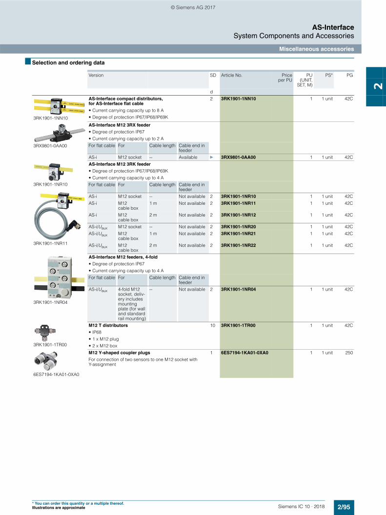
2/95Siemens IC 10 · 2018
AS-InterfaceSystem Components and Accessories
Miscellaneous accessories
2
* You can order this quantity or a multiple thereof.Illustrations are approximate
■ Selection and ordering data
Version SD Article No. Priceper PU
PU(UNIT,
SET, M)
PS* PG
d
3RK1901-1NN10
AS-Interface compact distributors, for AS-Interface flat cable
• Current carrying capacity up to 8 A• Degree of protection IP67/IP68/IP69K
2 3RK1901-1NN10 1 1 unit 42C
3RX9801-0AA00
AS-Interface M12 3RX feeder
• Degree of protection IP67• Current carrying capacity up to 2 AFor flat cable For Cable length Cable end in
feederAS-i M12 socket -- Available } 3RX9801-0AA00 1 1 unit 42C
3RK1901-1NR10
3RK1901-1NR11
AS-Interface M12 3RK feeder
• Degree of protection IP67/IP68/IP69K• Current carrying capacity up to 4 AFor flat cable For Cable length Cable end in
feederAS-i M12 socket -- Not available 2 3RK1901-1NR10 1 1 unit 42CAS-i M12
cable box1 m Not available 2 3RK1901-1NR11 1 1 unit 42C
AS-i M12 cable box
2 m Not available 2 3RK1901-1NR12 1 1 unit 42C
AS-i/Uaux M12 socket -- Not available 2 3RK1901-1NR20 1 1 unit 42CAS-i/Uaux M12
cable box1 m Not available 2 3RK1901-1NR21 1 1 unit 42C
AS-i/Uaux M12 cable box
2 m Not available 2 3RK1901-1NR22 1 1 unit 42C
3RK1901-1NR04
AS-Interface M12 feeders, 4-fold
• Degree of protection IP67• Current carrying capacity up to 4 AFor flat cable For Cable length Cable end in
feederAS-i/Uaux 4-fold M12
socket, deliv-ery includes mounting plate (for wall and standard rail mounting)
-- Not available 2 3RK1901-1NR04 1 1 unit 42C
3RK1901-1TR00
M12 T distributors
• IP68• 1 x M12 plug• 2 x M12 box
10 3RK1901-1TR00 1 1 unit 42C
6ES7194-1KA01-0XA0
M12 Y-shaped coupler plugs
For connection of two sensors to one M12 socket with Y-assignment
1 6ES7194-1KA01-0XA0 1 1 unit 250
© Siemens AG 2017

2/96 Siemens IC 10 · 2018* You can order this quantity or a multiple thereof.
Illustrations are approximate
AS-InterfaceSystem Components and Accessories
Miscellaneous accessories
2
Version SD Article No. Priceper PU
PU(UNIT,
SET, M)
PS* PG
d
3RK1901-1KA00
3RK1901-1KA01
3RK1901-1PN00
AS-Interface sealing caps
For free M12 sockets• M12 } 3RK1901-1KA00 100 10 units 42C
- Tamper proof 2 3RK1901-1KA01 100 10 units 42C• M 8 2 3RK1901-1PN00 100 10 units 42C
3RK1901-1MD00
AS-Interface M20 seals
• For AS-Interface cable, shaped• For insertion in M20 glands
2 3RK1901-1MD00 100 10 units 42C
3RK1901-3QM00
Cable adapters for flat cables
Connection of AS-Interface cable to metric gland with insulation piercing method• Continuation using standard cable
- For M16 gland 5 3RK1901-3QM00 1 1 unit 42C- For M20 gland 5 3RK1901-3QM10 1 1 unit 42C
• Continuation using pins- For M16 gland 10 3RK1901-3QM01 1 1 unit 42C- For M20 gland 5 3RK1901-3QM11 1 1 unit 42C
3RK1901-3QA00
Cable clips for cable adapters 5 3RK1901-3QA00 100 10 units 42C
3RK1901-1MN00
Cable terminating piece
For sealing of open cable ends (shaped AS-Interface cable) in IP67
} 3RK1901-1MN00 1 10 units 42C
3RK1901-2EA00
3RK1901-0CA00
Mounting plates
• K45- For wall mounting } 3RK1901-2EA00 1 1 unit 42C- For standard rail mounting } 3RK1901-2DA00 1 1 unit 42C
• K60, suitable for all K60 compact modules- For wall mounting } 3RK1901-0CA00 1 1 unit 42C- For standard rail mounting } 3RK1901-0CB01 1 1 unit 42C
© Siemens AG 2017

2/97Siemens IC 10 · 2018
AS-InterfaceSystem Components and Accessories
Miscellaneous accessories
2
* You can order this quantity or a multiple thereof.Illustrations are approximate
■ More information
3RK1902-0AR00
Sealing sets
• For K60 mounting plate and standard distributor• Cannot be used for K45 mounting plate• One set contains one straight and one shaped seal
2 3RK1902-0AR00 100 5 units 42D
Inscription labels
• For K45 and K60 compact modules• 20 x 9 mm, pastel turquoise• 19 frames with 20 labels each
15 3RT1900-1SB50 100 380 units 41B
3RK1902-4GB50-4AA0
Control cable, assembled at one end
Angular M12 socket for screw fixing, 4-pole, 4 x 0.34 mm2, A-coded, black PUR sheath, max. 4 A• Cable length 5 m 10 3RK1902-4GB50-4AA0 1 1 unit 42D
3RK1902-4CA00-4AA0
M12 socket, angled
For screw mounting, 4-pole screw terminals, max. 0.75 mm2, A-coded, max. 4 A
10 3RK1902-4CA00-4AA0 1 1 unit 42D
3RK1902-4BA00-5AA0
3RK1902-4DA00-5AA0
M12 connector
For screw mounting, 5-pin screw terminals, max. 0.75 mm2, A-coded, max. 4 A• Straight 10 3RK1902-4BA00-5AA0 1 1 unit 42D• Angled 10 3RK1902-4DA00-5AA0 1 1 unit 42D
3RK1902-4H...-5AA0
Control cable, assembled at one end
Angular M12 socket for screw fixing, 5-pole, 5 x 0.34 mm2, A-coded, black PUR sheath, max. 4 A• Cable length 1.5 m 10 3RK1902-4HB15-5AA0 1 1 unit 42D• Cable length 5 m 10 3RK1902-4HB50-5AA0 1 1 unit 42D• Cable length 10 m 10 3RK1902-4HC01-5AA0 1 1 unit 42D
3RK1902-4PB15-3AA0
Control cable, assembled at both ends
Straight M12 plug, straight M12 socket, for screw fixing, 3-pole, 3 x 0.34 mm2,A-coded, black PUR sheath, max. 4 A• Cable length 1.5 m• Also for addressing AS-i slaves with
M12 bus connection (e.g. K20, K60R compact modules, M200D motor starters)
10 3RK1902-4PB15-3AA0 1 1 unit 42D
Version SD Article No. Priceper PU
PU(UNIT,
SET, M)
PS* PG
d
More information
System Manual "AS-Interface"• German
https://support.industry.siemens.com/cs/de/de/view/26250840• English
https://support.industry.siemens.com/cs/ww/en/view/26250840
© Siemens AG 2017