arxiv:chao-dyn/9502010 v1 01 feb 95 - weizmann institute of … · 2016-08-08 ·...
TRANSCRIPT

arX
iv:c
hao-
dyn/
9502
010
v1
01 F
eb 9
5
LECTURE NOTES OF THE LES HOUCHES 1994 SUMMER SCHOOL
Exact Resummations in the Theory of Hydrodynamic Turbulence:
0. Line-Resummed Diagrammatic Perturbation Approach
Victor L’vov∗ and Itamar Procaccia†
Departments of ∗ Physics of Complex Systems and † Chemical Physics,
The Weizmann Institute of Science, Rehovot 76100, Israel,
∗Institute of Automation and Electrometry, Ac. Sci. of Russia, 630090, Novosibirsk, Russia
Abstract
The lectures presented by one of us (IP) at the Les Houches summer school dealt
with the scaling properties of high Reynolds number turbulence in fluid flows.
The results presented are available in the literature and there is no real need to
reproduce them here. Quite on the contrary, some of the basic tools of the field
and theoretical techniques are not available in a pedagogical format, and it seems
worthwhile to present them here for the benefit of the interested student. We
begin with a detailed exposition of the naive perturbation theory for the ensemble
averages of hydrodynamic observables (the mean velocity, the response functions
and the correlation functions). The effective expansion parameter in such a theory
is the Reynolds number (Re); one needs therefore to perform infinite resummations
to change the effective expansion parameter. We present in detail the Dyson-Wyld
line resummation which allows one to dress the propagators, and to change the
effective expansion parameter from Re to O(1). Next we develop the “dressed
vertex” representation of the diagrammatic series. Lastly we discuss in full detail
the path-integral formulation of the statistical theory of turbulence, and show
that it is equivalent order by order to the Dyson-Wyld theory. On the basis of the
material presented here one can proceed smoothly to read the recent developments
in this field.
Typeset using REVTEX
0
1. INTRODUCTION
The exact description of fluid flows is provided by the specification of the velocity field
u(r, t) as a function of space and time. Such a description is natural for “laminar” flows of
fluids whose velocity field is not strongly fluctuating in space and time. On the other hand,
for “turbulent” flows, which are states of fluids whose velocity field u(r, t) appears highly
erratic as a function of r and t, it is more sensible to consider a statistical description.
The statistical description is particularly useful in situations where the flow is driven by
stationary external agents. Examples of such stationary driving mechanisms are found in
shear turbulence, grid turbulence, convective turbulence, etc. It is believed that in such
flows it makes sense to consider long time averages of functions of the velocity field u(r, t).
For example, if the driving is arranged such that the fluid as a whole is confined in some
volume V , the mean velocity must vanish:
〈u(r, t)〉 ≡ 1
V
∫dr lim
T→∞1
2T
∫ T
−Tu(r, t)dt = 0 . (1.1)
The pointed brackets indicate here an average with respect to space and time. Likewise,
correlation functions can be defined:
〈u(r + r′, t+ τ )u(r, t)〉 (1.2)
≡ 1
V
∫dr lim
T→∞1
2T
∫ T
−Tu(r + r′, t+ τ )u(r, t)dt .
If the state of the fluid is statistically homogenous in space and time, the averaging process
(1.2) results in a function of r′ and τ only.
One of the most important open problems of statistical physics is whether the statistical
description of turbulence displays universal characteristics. Many important concepts were
developed in the attempt to answer this question. It was recognized by Richardson [1,2] in
the ‘20’s that quantities which depend on one space point have no chance to claim univer-
sality. The velocity field u(r, t) and all its functions are fatally sensitive to the large scale
components which are introduced by the external driving agents. In this picture the driving
acts on the large scales, leading to maximally large velocity fluctuations on the macroscale L,
which is known as the “outer” scale of turbulence. The typical scale of the velocity fluctua-
tions is denoted as UL. The order of magnitude of u(r, t) at every r is about UL. Richardson
suggested that the quantities that may have universal aspects are the velocity differences
δu(r + R, r, t) ≡ u(r + R, t)− u(r, t). In taking differences one eliminates the contribution
of the large scale motion, and may hope to see universal properties that are independent of
1

the driving mechanism. It was one of the main suggestions of Kolmogorov that for R that
is much smaller than L and much larger than a “dissipative” scale η, statistical averages of
functions of δu(r + R, r, t) may show universality. The dissipative scale η depends on the
kinematic viscosity of the fluid ν, and on the single most important dimensionless number
in the theory of turbulence, i.e. the Reynolds number Re. This number is defined as [3]
Re =ULL
ν, (1.3)
and in the Kolmogorov approach it is asserted that η/L ∼ Re−3/4. In other words, as
Re→∞ there is a larger and larger range of scales R for which functions of δu(r + R, r) are
expected to show universal properties.
In most experimental applications it is customary to consider the longitudinal component
of δu(r + R, r, t) only:
δu(r + R, r, t) ≡ δu(r + R, r, t) · RR. (1.4)
The essence of the Kolmogorov approach to the issue of universality in turbulence, which
was suggested in 1941 [4] (K41) is that it is possible to construct a local theory with one
universal scaling exponent. This universal exponent was ascribed to δu(r + R, r), stating
that
δu(r + R, r) ∼ R1/3 . (1.5)
It was asserted that δu(r + R, r) is the only scaling field that has to be considered, in the
sense that the structure functions Sn(R) which can be formed from δu(r + R, r, t) satisfy
the scaling laws
Sn(R) ≡ 〈〈[δu(r + R, r, t)]n〉〉∼ (εR)
nζn ∼ (εR)n/3 (1.6)
for values of R in the “inertial range” L � R � η. In (1.6) ε is the mean (really in the
double bracketed sense of (1.1) but defined by an overbar to save notation) of the dissipation
field ε(r, t),
ε(r, t) ≡ ν
2[∂αuβ(r, t) + ∂βuα(r, t)]2 . (1.7)
This suggestion of Kolmogorov was immediately attacked both by theorists (e.g. Landau)
and experimentalists (for a recent review see e.g. [5]). Indeed, it is rather astonishing
2

that a problem like fluid turbulence, which suffers from very large fluctuations and strong
correlations, should be amenable to such a simple description; even Kolmogorov himself
revised his thinking and changed (1.6) to a more complicated form (which fell under attack
as well). Indeed, one measurement that raised a lot of objections to the K41 approach is
the measurement of the correlation function of the dissipation field Kεε(r)
Kεε(R) = 〈ε(r + R, t)ε(r, t)〉 ∼ R−µ . (1.8)
where ε(r, t) = ε(r, t)− ε. It was found in experiments that Kεε(R) decays very slowly in
the inertial range, with µ having a numerical value in the range 0.20-0.25 [6]. It was claimed
that the K41 theory required µ to vanish. According ly, there have been many attempts to
construct models of turbulence to take (1.8) into account and to explain how the measured
deviations (ζn − 1/3) in the exponents of the structure functions were related to µ.
Our aim is to present a Navier-Stokes based theory of turbulence. This theory attempts
to study the universality of of turbulence on scales belonging to the bulk of the inertial
range using the equations of fluid mechanics. We are not going to review the variety of
phenomenological ad hoc models which have proliferated in recent years. It is our belief
that recent progress in the analytic theory brings us a long way towards understanding the
scaling properties of turbulence, and it is important at this point to examine carefully what
is known, to separate false starts from genuine progress, and to delineate the domain of firm
results. In doing so we will also attempt to carefully assess the main open problems that
await further research.
The equations of fluid mechanics are partial differential equations, and it is natural to
consider them as a classical field theory, and to attempt to apply techniques of perturbation
theory and renormalization that found spectacular success in the context of quantum field
theory. Indeed, such attempts were made with the help of various closure procedures like
Kraichnan’s Direct Interaction Approximation [7] and many others (for review of different
closure schemes see, e.g. [8]). A more systematic approach was suggested to be found
within diagrammatic perturbation approaches for non-equilibrium processes like the Wyld
diagrammatic technique [9] for the Navier-Stokes equation. Generalizations of the Wyld
diagrammatic technique were suggested by Martin, Siggia, Rose [10] and by Zakharov and
L’vov [11].
In performing such calculations one faces several serious difficulties. Firstly, turbulence
has no small parameter. The naive perturbation expansion of the Navier-Stokes equations
results in increasing powers of the Reynolds number, and this is rather inconvenient in a
situation where one is interested in the limit Re� 1. Wyld [9] found a way to overcome this
3

difficulty; by performing line renormalization like Dyson’s quantum field analog one finds a
perturbative theory in which the coupling parameter is of O(1). This is an important step,
but it does not save Wyld’s theory from severe problems. The main problem of the Wyld
theory is that it is written in terms of the correlation functions of the field u(r, t) itself.
As mentioned above, such quantities are not universal, and they are dominated by large
scale contributions. In addition, functions of u(r, t) itself are not Galilean invariant. Wyld
attempted therefore to work in terms of Fourier transforms of these quantities. Indeed,
the correlation functions in k, ω representation are expected to be universal in the regime
1/η � k � 1/L. Unfortunately, the theory in k, ω representation involves integrals over the
whole k, ω range, and the theory picks up infra-red divergences that cannot be eliminated
easily.
Kraichnan has suggested that a theory that does not suffer from the problems of Wyld’s
expansion can be formulated in Lagrangian coordinates [12,13]. From the point of view of
developing the theory in terms of universal quantities this suggestion was correct. Unfortu-
nately the perturbation theory which is based on the Lagrangian representation is not of the
diagrammatic type, and higher order terms with its coefficients cannot be found simply on
the basis of topological features of the diagrams. We shall not be interested here in theories
that contain arbitrary truncations. Such theories are uncontrolled, and it is our hope that
one can achieve a fully controlled theory of turbulence. We seek therefore a formulation that
lends itself to a diagrammatic description and which comes as close as possible to using as
building blocks functions of δu(r + R, r). A theory that has all the right ingredients was
formulated by Belinicher and L’vov [14] (see also [15]). This theory went under the name
“quasi-Lagrangian”; this name turned out to be unfortunate, since it left the impression of
an approximate theory. Recently [16] we revisited this theory and reiterated that it is not
an approximate theory, but rather an exact renormalization scheme that differs from the
Wyld technique.
The aim of these notes is to review the basic tools of the field theoretic diagrammatic
approach to the Navier-Stokes problem. There are essentially no new developments in these
notes, but they are meant to bring the student to a level of expertise that would allow a
smooth entry into the latest developments. We develop in full detail the naive perturbation
theory (sec.2) for the Green’s function and the 2-point correlation function. This theory
is badly diverging in powers of Re. In sec.3 we discuss the line resummation which results
in the Dyson equation for the Green’s function and the Wyld equation for the correlator.
In these equations, which are also presented as infinite diagrammatic series expansions, the
4

effective coupling constant is of O(1). We discuss briefly 3-point and higher order correlation
functions, and in Sect. 4 we turn to the functional integral formulation of the renormalized
perturbation theory. We show in detail that the diagrammatic expansion obtained in this
formulation is identical, order by order, with the Wyld formulation, and that either one
can be used at will [10,17,18]. The interested student is invited then to continue reading
Refs. [16,19,20] in which the Belinicher-L’vov renormalization scheme is used to develop a
consistent theory of normal and anomalous scaling in turbulence.
2. NAIVE PERTURBATION THEORY
A. Introduction
As was mentioned in section 1, we are mostly interested in the calculation of averages
and correlation functions, which are obtained in the long time limit of the forced Navier-
Stokes equations. Since the equations contain a viscous damping, it is assumed that the
balance between forcing and damping leads after a time to stationary statistics which are
independent of the initial conditions. Roughly speaking the picture is of a nonlinear problem
that generates its own ergodic measure, and the forcing is chosen such that the ergodic
measure (at least as far as the calculated quantities are concerned) is a property of the
Navier-Stokes equations and not of the forcing. In other words, the solution roams forever
on a strange attractor, and the forcing is used mainly to keep the system away from the
(stable) zero solution, but without ruining too much the measure on the attractor.
In our formal scheme we will expand ergodic averages for the nonlinear problem in terms
of averages of solutions of the linear problem (i.e with the nonlinearity discarded). Not
surprisingly, since the measure of the nonlinear problem is very different from the measure of
the linear problem, we will see that our expansion has very miserable convergence properties.
Actually the naive expansion is diverges, and it cannot be truncated at any order. Its
has meaning only for the series as a whole. Nevertheless, one can perform infinite partial
resummations of this series to achieve a new series that has somewhat better properties,
i.e. the terms remain all of the same order. We stress right at the beginning that many of
our steps have dubious mathematical validity, and the fact that they are common practice
in many field theories cannot be really taken as an excuse. At least we will not hide the
difficulties.
The Eulerian velocity field is denoted in our discussion as u(r, t). In later notation we
5

shall sometimes use the 4-vector notation u(x), where x ≡ (r, t). In the mathematical
literature it is customary to write the Navier-Stokes equations as an initial value problem
without any type of forcing:
∂u
∂t+ (u ·∇)u − ν∇2u−∇p = 0 , ∇ · u = 0 . (2.1)
For the physicist the equations of fluid mechanics are a projection onto a set of slow variables
of the many-body microscopic dynamics. In such a projection, when successful, the host
of irrelevant degrees of freedom remain in the form of a “noise” term in the equation of
motion of the slow variables. The basic assertion is that the irrelevant degrees of freedom
are much faster, and reach local equilibrium on a short time scale which is irrelevant for the
hydrodynamic description. Thus, the physicist writes Eq. (2.1) in the form
∂u/∂t+ (u ·∇)u− ν∇2u−∇p = f , (2.2)
where the fluctutation dissipation theorem dictates that the two-point correlation function
of the “random” force f is related to the viscosity and the temperature of the fluid:
fα(r, t)fβ(r′, t′) = 2νTδ(r− r′)δ(t− t′)δαβ . (2.3)
An overbar denotes an average with respect to the thermodynamic equilibrium ensemble
with temperature T .
In natural conditions turbulence arises either due to the instabilitiy of laminar flows (like
in channel flow) or due to time dependent stirring (such as in a glass of water stirred by
a spoon). For the sake of theoretical simplicity we will model all these situations with a
stirring force φ(r, t). The properties of the turbulent flow may depend on the nature of the
stirring force φ(r, t). Since in experimental situations one finds that the statistics of the
turbulent velocity field on the large scales are close to that of a Gaussian random ensemble,
it is customary to take f(r, t) to be a Gaussian random force with spectral support in the
small wave vectors and small frequencies. The properties of the correlation function of
φ(r, t) are best stated in k, ω space: it is concentrated in the small k, ω region, i.e. k ≤ 1/L,
ω ≤ UL
where UL
is the characteristic magnitude of turbulent velocity fluctuations. In order
to model properly the generic properties of turbulent fluids one needs to assume that the
correlation decays sufficently quickly to zero for k � 1/L, ω � UL/L. In r, t space it means
that D(R, τ ),
Dαβ(R, τ ) = 〈〈φα(r + R, t+ τ )φβ(r, t)〉〉 (2.4)
6

is constant for r � L, τ � L/U and for higher values of R and τ it decays quickly.
One of the important questions that the theory should address is whether the properties of
turbulence on scales much smaller than L are independent of the precise choice of D(R, τ ).
Also, the possible effect of non-Gaussianity of the forcing should be understood.
Adding the stirring force to the equation of motion we write
∂u/∂t+ (u ·∇)u− ν∇2u−∇p = f + φ . (2.5)
The combination f + φ will be referred to, when convenient, as f .
In this work we deal with incompressible turbulence only, in which ∇ · u = 0. We shall
therefore project out from Eq. (2.5) any longitudinal components. This is done with the
help of the projection operator↔P which is formally written as
↔P ≡ −∇−2∇×∇×. In tensor
notation this operator is Pαβ = δαβ −∇−2∇α∇β. Because of the inverse Laplace operator
which is nonlocal in space, the application of↔P to any given vector field a(r) is non local:
[↔Pa(r)]α =
∫dr′Pαβ(r− r′)aβ(r′) , (2.6)
where Pαβ(r− r′) is the inverse Fourier transform of Pαβ(k)
Pαβ(r− r′) =∫
dk
(2π)3exp[−i(r− r′) · k]Pαβ(k). (2.7)
The tensor Pαβ(k) in k-representation is
Pαβ(k) = δαβ −1
k2kαkβ (2.8)
and in r-representation
Pαβ(r− r′) =δαβ|r− r′|3 − 3
(rα − r′α)(rβ − r′β)
|r− r′|5 . (2.9)
The operator↔P has the following properties: (i)∇ ·
↔P =
↔P ·∇ = 0. (ii) For any divergence-
free vector b,↔Pb = b. Applying
↔P to Eq. (2.5) we find
(∂/∂t− ν∇2)u +↔P(u ·∇)u =
↔Pf . (2.10)
Introduce the bare Green’s operator G0 via the relationship
↔G0 ≡
i
∂/∂t− ν∇2
↔P . (2.11)
Using↔G0 we can rewrite Eq. (2.10) in the form:
7

u(r, t) = u0(r, t)− i↔G0(u ·∇)u , (2.12)
where
u0(r, t) ≡ −i↔G0f . (2.13)
The meaning of the application of↔G0 to any vector field c(r, t) is understood by
↔G0c(r, t) = G0
αβ(r− r′, t− t′) ∗ c(r′, t) (2.14)
≡∫dr′dt′G0
αβ(r− r′, t− t′)cβ(r′, t′) ,
where the kernel G0αβ(r − r′, t− t′) is the Green’s function of the linear part of Eq. (2.10),
and we have introduced the * operation according to the RHS of Eq. (2.14). The explicit
representaion of G0αβ(r− r′, t− t′) is given as the inverse transform in k and ω
G0αβ(r− r′, t− t′) (2.15)
=∫dkdω
(2π)4exp i[k · (r− r′) + ω(t− t′)]G0
αβ(k, ω) .
The function G0αβ(k, ω) is
G0αβ(k, ω) =
Pαβ(k)
ω + iνk2. (2.16)
The convention chosen is that G0αβ(k, ω) is analytic in the upper half of the plane of complex
ω. Correspondingly G0αβ(r− r′, t− t′) is zero for t′ < t. This property is known as causality,
and it stems from the phyiscal constraint that a response cannot come before its cause.
It is obvious that the solution (2.12) involves integrals over all space in r, t representation
because of the inverse operators in↔G0 which is a factor function in k, ω space. The solution
involves integrals also in k, ω space due to the nonlinear term which is a local operator in
r, t space. Thus there is no formal advantage to either representation, and we shall write
Eq. (2.12) in the representation invariant form
u = u0 +1
2G0 ∗ Γ·u·u . (2.17)
The * and the · operations depend on the representation. In r, t representation the
* operation was defined by Eq. (2.14), and Γ·u·u means 2(u ·∇)u. For later applications we
need to consider the operation Γ·u·u in which different fields u and u are involved. We will
interpret Γ·u·u in a symmetric fashion, i.e.
Γ·u·u = −i[(u ·∇)u + (u ·∇)u] . (2.18)
8

In Fourier representation we write
u(k, ω) ≡∫drdt exp[−i(r · k + ωt)]u(r, t) , (2.19)
[G0 ∗ c
]α
= G0αβ(k, ω)cβ(k, ω) , (2.20)
and
[Γ·u·u]α(k, ω) =∫
dk′
(2π)3
dk′′
(2π)3
dω′
2π
dω′′
2π
× Γαβγ(q, q′, q′′)u∗β(k′, ω′)u∗γ(k
′′, ω′′) (2.21)
where
Γαβγ(q, q′, q′′) = (2π)4(kβδαγ + kγδαβ)
× δ(k + k′ + k′′)δ(ω + ω′ + ω′′) . (2.22)
In these equations and below we introduced the four dimensional vector q ≡ {k, ω}. The
symmetry of (2.21) with respect to exchanging u and u is inherited from (2.22).
B. Naive Perturbation Theory for the velocity field
It is natural to seek solutions of Eq. (2.17) in the form
u(r, t) =∞∑
n=0
un, un ∝ Γn . (2.23)
Substituting this in the Navier-Stokes equation in the form (2.17), and collecting terms with
the same power in Γ we have a set of recurrence relations starting with
u1 =1
2G0 ∗ Γ·u0
·u0, (2.24)
u2 =1
2G0 ∗ Γ·u1
·u0+
1
2G0 ∗ Γ·u0
·u1= G0 ∗ Γ·u1
·u0. (2.25)
The last equality follows from the symmetry of Γ which was discussed in the previous
section. In fact, we are making full use here of the fact that we study a classical system. In
the corresponding quantum mechanical theory the two terms in Eq. (2.25) are distinct due
to the non-commutativity of u1 and u0 which become operators.
The next orders have the form
u3 = G0 ∗ Γ·u2·u0
+1
2G0 ∗ Γ·u1
·u1, (2.26)
u4 = G0 ∗ Γ·u3·u0
+ G0 ∗ Γ·u2·u1, (2.27)
9

etc. In general,
un =n/2−1∑
m=0
G0 ∗ Γ·un−m+1·um (n even) , (2.28)
un =(n−3)/2∑
m=0
G0 ∗ Γ·un−m+1·um
+1
2G0 ∗ Γ
·u(n−1)/2·u(n−1)/2 (n odd) . (2.29)
At this point one may substitute lower order um in (2.28) and (2.29) to achieve eventually
a solution in terms of u0 and G0. For example u2 can be written as
u2 = G0 ∗ Γ·(1/2)Γ
·u0·u0·u0 (2.30)
10

FIGURES
U , u o ,
* :
F , ,F o
G , G o .
Γ
~ ~
~~~
~ ~FIG. 1. Graphical notation for the perturabtion expansion. The symbol used are the following:
short wavy lines stand for the fluid velocity (think about waves). A thin wavy line stands for u0,
whereas a bold wavy line represents the full solution u(r, t). A straight line stands for the field
p(r, t) that is only introduced in Chapter III. The Green’s function, which is the response in the
velocity to some force is made of a short wavy line and a short straight line representing the force.
Again this symbol appears in thin and bold variants. The former stands for the bare Green’s
function (2.11), and the bold for the dressed Green’s function (3.5). The vertex (2.18) is a fat dot
with three tails. One straight tail belongs to the Green’s function, and two wavy tails stand for
velocities. A long wavy line will represent correlation functions of velocities. Again, the thin and
bold variants are bare and dressed correlators respectively.
For higher values of n this substitution becomes increasingly more cumbersome in ana-
lytic form, and it is very helpful to represent it graphically. The notation used is shown in
Fig. 1. In Fig. 2a we display the diagrammatic representation of the equation of motion, and
in Fig. 2b and Fig. 2c we show the diagrammatic form of Eqs. (2.24) and (2.30). Examining
the other graphs in Fig. 2 we see the great advantage of the diagrammatic representation.
It is very easy to write the n’th order diagrams without going through the cumbersome
analytic substitutions. The rules for drawing the diagrams are very simple: for the n’th
order term we draw all the topologically distinct binary trees with n vertices, such that all
the trunks are made of Green’s functions and all the end branches are made of u0’s. Every
portion of the tree that continues in a symmetric fashion gets a factor of 1/2. That is all.
The existence of these simple rules for finding the n’th order term, which are independent of
n, reflects the internal sturcture of this perturabtion theory, and it will allow us to perform
resummations in a straightforward way.
It should be understood that the perturbation theory described in this section is not
expected to converge. Consider for example the ratio of u1 over u0. “Dividing” Eq. (2.24)
11

by u0 leaves us with the order of magnitude estimate
u1/u0 ∼G0 ∗ Γ·u0· ∼∇u0/ν∇2 ∼ u0L/ν = Re . (2.31)
We see that we are effectively expanding in Reynolds number, and for high Re this is a
terribly divergent series. The main problem in this expansion is the appearance of the
molecular viscosity ν in the denominator in (2.31). It is expected that in a turbulent fluid
the viscosity is strongly renormalized because of the interaction, yielding the so called “eddy-
viscosity”. We need to reformulate the theory such that the eddy-viscosity appears in the
effective expansion parameter to make it of order 1. This is achieved in Sect.2.
1
(a)
(c)(b)
1
2 A
u 2 = u 1 = 1 A
3 4
(e)
1
2
3
4 5
u 4 =
+
4 A 4 C
u = = +
(d)
+
1 2 3 4
1
2
3 B 3 A
2 3
12
12
12
12
12
12
12
12
12
12 1
2
= u 3
12
+
4 B
2
1/2
1/2
1/2
1/2 1/2
1/2
1/2
1/21/2
1/2
1/2
1/2
1/2
12

FIG. 2. Graphic representation of the equation of motion [Panel (a)] and the naive perturba-
tion theory. The diagrams in Panels (b)-(d) are all the contributions appearing in u1 − u4. Note
that all the topologically distinct trees appear. These trees have a trunk that begins with the wavy
line of a bare Green’s function, and continues all the way via bare Green’s functions. The branches
are made of wavy lines of u0. The bifurcations carry a vertex Γ. The factors of 1/2 appear in all
the bifurcations that have symmetry above them. The total factor in front of a tree is the product
of these numbers. Every tree has been denoted with a letter and a superscript. The latter stands
for the order in Γn. For future purposes we have numbered the branches of the trees 2A,3A,3B
and 4A.
C. Naive perturbation theory for statistical quantities
1. Statistics
As explained in the Introduction, our aim is to formulate a theory for ergodic averages.
In the naive perturbation theory we can compute such averages by using the expansion (2.23)
for u(r, t), and averaging products of u0(r, t) at different points and times with respect to
different realizations of the random forcing f . In doing so we shall make full use of the fact
that f is assumed to be Gaussian. On the one hand, this leads to a great simplification of the
naive perturbation theory. On the other hand it seems theoretically dangerous. The physics
that we are trying to describe is surely non-Gaussian. Are we not throwing away important
aspects of the physics by using from the start a Gaussian forcing? The answer will be NO.
We shall see later that the structure of the theory in its final resummed formualtion does
not depend on this way of constructing the naive expansion. The physics is dominated by
strong interactions via the nonlinearity, and a Gaussian forcing is sufficient to excite all the
possible responses which the dynamics amplifies and redistributes to allow us to observe the
full statistical structure. In fact, at the end of the calculation we are going to explore the
limit in which the random forcing becomes vanishingly small. We shall show that this limit
exists, and that in that limit the statistics of velocity fluctuations becomes independent of
the statistics of the random force. Notwithstanding, it should be said here that it is not
at all obvious that the procedure followed here is the most efficient one. It is possible that
one can get a better converging theory by forcing the system with a force that is closer in
13
character to the statistics of the dressed system. We do not know how to do that, and this
is one of the open problems that needs to be studied in the future. We shall return to this
issue in Sec. 3 after the formal apparatus needed for its full appreciation is already at hand.
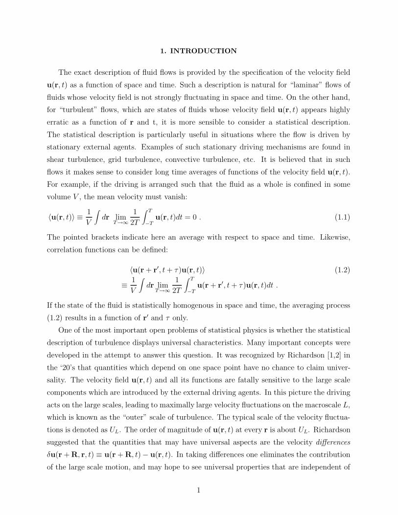
We will denote averages with respect to the realization of the random force with single
pointed brackets, in contrast with the double pointed brackets of Eq. (1.1). The Gaussianity
of the random force means that
〈f (x)〉 = 0 ,
〈f(x1)f(x2)〉 = D12 ,
〈f (x1)f(x2)f(x3)〉 = 0 (2.32)
〈f (x1)f (x2)f(x3)f(x4)〉 = D12D34 +D13D24 +D13D23 ,
etc. All higher order correlations with odd number f vanish, and the correlations involving
2n factors of f have (2n − 1)!! contirbutions corresponding to all the possible pairings of f .
(b)
(a)
< u > = 1
+ + + 3 A 1
3 A 23 B 1
3 B 2
12
12
12
121
2
12
1/2
1/2 1/2
1/2
1/2
1/2
1/2
< u > = 3
14

FIG. 3. The diagrams representing the mean velocity. Panel (a) represents the first order
contribution in Γ, and is obtained from the simple gluing of the two branches of the tree 1A in
Fig. 2b. It carries the factor of 1/2 which originates from the symmetry of 1A. Clearly, averaging
either 2A of Fig. 2c or any tree in Fig 2e results in a zero contribution due to the odd number of
branches which carry a random force: 〈u2〉 = 〈u4〉 = 0. Panel (b) represents the result of averaging
of the trees 3A and 3B in Fig. 2d. The diagran 3A1 originates from gluing of the branches 1 with 2
and 3 with 4 in 3A. Diagram 3A2 comes from gluing either 2 with 3 and 1 with 4 or 1 with 3 and
2 with 4 in 3A. Correspondngly we gain a factor of 2 with 3A2 leading to a coefficient 1/4 instead
of 1/8 in 3A. The tree 3B1 originates from 3B after gluing 1 with 3 and 2 with 4 or 1 with 4 and
2 with 3. A factor of 2 is gained. Lastly, diagram 3B2 results from gluing 1 with 2 and 3 with
4 in 3B. There is only one way of doing it, and the factor 1/2 remains. The general rule for the
overall factor in front of a diagram is obtained as follows: count the number of vertices such that
that exchanging the two branches emanating from them leaves the diagram invariant. Denote the
numebr of distinct pairs of such branches by N . The overall factor in front of the diagram is 1/2N .
2. The mean velocity
Of the sought statistical quantities, the easiest to obtain is the mean velocity, averaged
over all the possible realizations of the random force. Since this random force is Gaussian,
we have well defined statistics for the averaging process. We can apply the rules (2.32) to
the average of the diagrammatic representation of u(r, t). We pair the u0 branches in all the
possible ways, and glue the ends together, see Fig. 3. Every diagram with an odd number
of u0 branches gives no contribution. Every diagram with 2n u0 branches gives (2n- 1)!!
contributions which are obtained from all the possible binary pairings of random forces. The
process is shown in Fig. 3. The diagrams nAm and nBm for 〈un〉 in Fig. 3 result from the
diagrams nA and nB for un in Fig. 2. Note that in systems which are homogeneous and
isotropic the mean velocity vanishes. Consequently, the sum of all the diagrams obtained
in this fashion has to vanish. This will be used in our later developments. In a turbulent
system with a space dependent mean velocity profile this set of diagrams will not vanish, and
it will contribute also in other statitsitcal averages that we consider below. These diagrams
will describe the interaction of the mean profile with the velocity fluctuations.
15

3. The Green’s function
Next we discuss the Green’s function, which is the response of the velocity field to an
external perturbation. The Green’s function is defined as
Gαβ(x, x′) = i⟨δuα(x)/δfβ(x′)
⟩(2.33)
where the notation δ(·)/δ(·) stands for the functional derivative. The meaning of this func-
tional derivative is the following: solve the Navier-Stokes equations once with a forcing f
and once with a forcing f + εδ(x− x′). Then take the ratio [u(x, ε)−u(x, 0)]/ε in the limit
ε → 0, and average over the ralizations of the random force. The principle of causality
means that G(x, x′) is zero for t′ < t. This property will be used a lot in the sequel.
The calculation of the functional derivative using the diagrams in Fig. 2 is straightfor-
ward. Every diagram having n branches of u0 contains a product of n f ’s. The calculation
of the derivative with respect to δ f(x′) means via the chain rule that we get n contributions
to δu(x)/δf(x′). Every such contribution is obtained by dropping one of the branches of u0,
and replacing it by branch of G0. An example of how this procedure is done for diagrams2A and 4A in Fig. 2 is shown in Fig. 4a and Fig. 4b respectively.
The second step is obtained by averaging the diagrams for δu(x)/δ f(x′) over realizations
of f(x′). We can apply the rules (2.32) to the averages of the diagram of δu(x)/δ f(x′) in a
graphical sense. This procedure is done in Fig. 5. Fig. 5a contains the two contributions to
G2, and Figs. 5b and 5c show all the 19 diagrams for G4. The diagram denoted nAmp are
obtained from the diagrams nAm in Fig. 4. The diagrams denoted nBmp and nCmp originate
from diagrams nB and nC in Fig. 2. Notice that every diagram has an “entry” which is the
root of the tree in Fig. 2, and an “exit” which is the branch G0 which replaced a branch of
u0. There is a unique path between entry and exit which is composed of a chain of G0 ’s.
We shall call this path the “principal path” of the diagram. Notice that the entry always
begins with a wavy line, whereas the exit ends with a straight line. In fact, all the diagrams
appearing here can be drawn without reference to the explicit derivation described here
using simple topological rules. However, since the diagrams described here are not in their
final form we defer the discussion of the appropriate rules for a later moment.
16

Fig 4b
+
1
2
3
22A 2
2A
5
+
4
+3
1 2
43A
3 4
5 +
1 2
44A
4 5
(a)
(b)
12
32
1
12
3
1
2
4 5
+4
2A
3
2
1
12
12
41A
1/2
1/2
1/2
1/2
+
FIG. 4. Typical contribution to the diagrammatic representation of δu(x)/δf which originates
from the trees 2A and 4A in Fig. 2c and 2e. In panel (a) we show the diagrams originating from 2A
and in panel (b) those originating from 4A. The diagram 2A2 is obtained by differentiating with
respect to f(x′) at position 2 or 3 in 2A. A factor of 2 is gained. The diagram 2A1 comes from
differentiating with respct to f(x′) at position 1. The diagram 4A4 is obtained by differentiating
with respect to f(x′) at position 4 or 5 in 4A. A factor of 2 is gained. The diagrams 4A3 ,4A2 and
4A1 come from differentiating with respect to f(x′) at positions 3, 2 and 1 respectively. Again the
factor 1/2 remains at vertices that have symmetry above them.
17

+
+
G2 =
(b)
+
(a)
41A4
+G4 =
+
4A11
+ ++
++
+
+
12
+
4A 12
12
A211A2
211
2
A442 43
4A
4A 22
12
4A 21
1/2
1/2
1/2
1/2
4A 31 324A
+
+
+
+
+
B431 B4
32
C412
C422
+
+
+
C411
C421
( c )
12
12
12
12
12
12
12
12
12
+
B4211
21
2
+
B4221
2
1/2
1/2 1/21/2
1/2
1/2
1/2
1/2
1/2
1/2
1/2
1/2
B411
4B 12
FIG. 5. Diagrams for the Green’s function. Panel (a): The contributions to G2 originate
from the trees shown in Fig. 4a by gluing two u0 branches in the only possible way. Panel (b):
The contributions to G4 originating from the trees 4A1 −4 A4 shown in Fig. 4b. The diagrams
4A41 −4 A43 come from 4A4 by gluing 1 - 3 and 2 - 4; 1 - 4 and 2 - 3 ; 1 - 2 and 3 - 4 repsectively.
The diagrams 4A31 come from 4A3 by gluing 1 - 4 and 2 - 5 or 1 - 5 and 2 - 4. A factor of 2 is
gained. 4A32 is obtained by gluing 4A3 at positions 1 - 2 and 4 - 5. The diagram 4A21 comes from
4A2 by gluing 1-3 and 4-5. 4A22 is obtained by gluing 1-4 and 3-5 or 1-5 and 3-4, gaining a factor
of 2. Finally 4A11 comes from 4A1 by gluing 2-4 and 3-5 or 2-5 and 3-4. 4A12 obtains from 4A1 by
gluing 2-3 and 4-5. (c) Diagrams for G4 originating from 4B and 4C in Fig. 2e. Note that again
all the numerical factors follow the same rules as observed in Fig. 4.
18

4. The 2-point velocity correlation function
The 2-point velocity correlation function F(x, x′) is defined as
Fαβ(x, x′) = 〈uα(x)uβ(x′)〉 . (2.34)
The calculation of this quantity is again based on the diagrammatic expansion shown in
Fig. 2. To obtain Fm+p of order Γm+p we need first to take a contribution um and a
contribution up and mutiply them together. The n-th order Fn is obtained as a sum of
all Fm+p such that m + p = n. In the second step we average over the realizations of f .
As before all odd order contributions vanish because they contain an odd power of f . For
example,
F0(x, x′) = F0+0(x, x′),
F1(x, x′) = F1+0(x, x′) + F0+1(x, x′) = 0 , (2.35)
F2(x, x′) = F2+0(x, x′) + F1+1(x, x′) + F2+0(x, x′) ,
where
Fm+p(x, x′) = 〈um(x)up(x
′)〉 . (2.36)
To obtain the diagrammatic representation of this procedure we take one tree for um(x)
and one tree for up(x′) from Fig. 2, and average the product of these trees according to the
rules (2.32). In other words we need to pair the branches of u0 in all the possible ways, and
to glue them as discussed before in computing 〈u〉 and the Green’s function. The procedure
is shown in Fig. 6. Note that every diagran has a uniquely defined ”principal cross section”
which arises from the gluing of the two trees um(x) and up(x). We denote it in the diagrams
as a vertical broken line, and we draw the reader’s attention to the fact that the principal
cross section cuts through correlators only, and not through Green’s functions. This fact is
used later in the process of resummation.
This is the end of the naive perturbation theory. As we saw, it is an expansion in powers
of Re, and we are going to partly resum this expansion to develop a reformulation with a
better expansion parameter. We reiterate here that the procedure at this point seems very
dependent on the properties of the noise, since we used the rules (2.32) time and again. We
defer further discussion of this issue until after the resummations of various sorts, when we
can take the limit f → 0 with impunity.
19

3. RESUMMATIONS
In this chapter we discuss the resummation of the naive perturbation theory that was
developed in Chapter 2. We begin with the mean velocity and its role in the resummation
of the Green’s function and the correlator.
(a)
(c)
3 4
+F1+1
> =
x x' x x' x x'
( )
x x x'
(b)
+F0+2
= < > =x x' x'
1
2
3 4
34
F4 =x
21
1
x'
+
+
3
6
+ +
5
+ +
12
12
12
12
12
12
4
12
21
2
1 2
= <1
21/2 1/2 1/2 1/21/2 1/2
1/2
1/2
1/2
1/2
20

FIG. 6. Diagrammatic representation of the 2-point velocity correlation function. Panel (a):
F1+1 is obtained from the the trees u1(x) and u1(x′). Diagram 1 is obtained by gluing 1-2 and
3-4, and diagram 2 by gluing 1-3 and 2-4 or 1-4 and 2-3, gaining a factor of 2. Panel (b): F0+2 is
obtained from the trees for u(x) and u2(x′). Diagram 1 is obtained by gluing 1-2 and 3-4, while
the diagram 2 comes from gluing 1-3 and 2-4 or 1-4 and 2-3, gaining a factor of 2. Panel (c): Some
typical diagrams contributing to F4. Note that all the diagrams have a “principal cross section”
that separates trunks belonging to the left and to the right trees. This cross section runs through
2-point correlators, never through Green’s functions. In contrast with the diagrams for the Green’s
function that have wavy entries and straight exits, here we have wavy entries on both sides. The
rules for the numerical factors of the diagrams remain the same.
A. The resummation of the mean velocity
In Section 2B we discussed the diagrammatic series for 〈u〉 (see Fig. 3) , and commented
that it has to sum up to zero when 〈u〉 = 0. In discussing the diagrams for the Green’s
fucntion Fig. 5 and for the correlator Fig. 6 we encounter again the same type of diagrams
that appear in 〈u〉. For example in Fig. 5 the diagrams 2A11,4A32,
4A21,4A11,
4B21,4B31,
and 4C11 all have a fragment which is the diagram for 〈u1〉 in Fig. 3a. In addition, the
diagram 4A11 has a fragment which is identical to 3B1 in Fig. 3. The diagram 4A12 has a
fragment like 3B2. The diagram 4C21 has a fragment like 3A2, and lastly 4C22 exhibits a
fragment like 3A1.
All these diagrams that contain fragments belonging to 〈u〉 have a common feature. To
see this denote the part of any diagram that contains the principal path between entry and
exit as the “body” of the diagram. Any fragment that can be disconnected from the body
by cutting one Green’s function is called a “weakly linked” fragment. All the diagrams that
we discussed in the previous paragraph have weakly linked fragments. Consider now all the
diagrams in Fig. 5 that have two Green’s functions in their principal path. These are the
diagrams 2A11,4A11,
4A12,4C21 and 4C22. The sum of the weakly linked fragments of these
diagrams is exactly 〈u1〉 + 〈u3〉 as can be seen in Fig. 3. If we consider all the higher order
diagrams for G which have two Green’s functions in the principal path, we find that their
weakly connected fragments furnish all the remaining diagrams in the series for 〈u〉. The
coefficients in front of all these fragments is the same as the coefficient in the series for 〈u〉
21

since it is determined uniquely by the local topology of the fragment, independently of the
position that the fragment occupies in the mother diagram. Accordingly all these diagrams
with two Green’s functions in the principal path sum up to zero. The same story repeats
for all the diagrams that contain a weakly linked fragment. For example the diagram 4A21
in Fig 5b is the first in the series that exhibits a weakly linked fragment that eventually
will be resummed together with diagrams that have the same body, but higher order weakly
linked contributions that sum up to zero. The general conclusion is that all the diagrams
that have at least one weakly linked fragment sum up to zero and need not be considered
further in the resummed theory.
Next we discuss the appearance of 〈u〉 in the series for the 2-point correlation fucntion.
In this series we find a new type of diagram, like diagram 1 in Fig. 6a. These are unlinked
diagrams which are obtained from averaging the left and the right tree separately. Such
diagrams contain no correlators that cross the principal cross section. Obviously such dia-
grams will resum to 〈u〉2 which is zero. In addition we have diagrams with weakly connected
fragments. In the context of the diagrams for the 2-point correlator we define the body of
the diagram as the part that contains the two entries (the roots of the original trees), which
are denoted by “x” and “x′” in all the diagrams in Fig. 6. A weakly linked fragment is a
fragment that can be disconnected from the body of the diagram by cutting off one Green’s
function. An example of such a diagram is diagram 1 in Fig. 6b. As in the case of the
Green’s function, the infinite sets of weakly linked fragments with the same body resums to
〈u〉 = 0. From this point on we therefore discard all the diagrams that have at least one
weakly connected fragment.
B. The Dyson resummation for the Green’s function
In this section we discuss the Dyson line resummation of the series for the Green’s
function. To this aim we classify the diagrams into three classes. The first class consists of
diagrams with weakly linked fragments which are all discarded. The other two classes are
designated as follows:
I. Principal path reducible diagrams. These are diagrams that can be split into two
disjoint pieces which contain more than one Green’s function, by cutting one bare Green’s
function that belongs to the principal path. An example of such a diagram is 4A43 in Fig. 5b.
This diagram fall into two parts by cutting G0(x2, x3).
II. Principal path irreducible diagrams. These are the diagrams that cannot be split as
22

described in I. All the other diagrams in Fig. 5 that do not have weakly linked fragments
are principal path irreducible.
All the principal path irreducible diagrams, except G0(x, x′) itself, share the property
that they start with a bare G0(x, x1), they end up with a bare G0(x2, x′), and in between
they have a principal path irreducible structure, say S(x1, x2). The sum of all these ir-
reducible structures is defined as the Σ operator, which will be shown to contain all the
information about the turbulent eddy viscosity. Using the diagrams in Fig. 5 we develop the
diagrammatic expansion for Σ(x, x1) which is shown in Fig. 7. With the help of Σ(x1, x2)
we can say that the sum of all the principal path irreducible diagrams is
Sum of all irreducibles (3.1)
= G0(x, x′) + G0(x, x1) ∗ Σ(x1, x2) ·G0(x2, x′)
where the star “∗” and dot “·” products are as defined in the vertex Eq. (2.17). The operator
Σ(x1, x2) starts and ends with a vertex, and it therefore connects with “∗” to the preceding
G0(x, x1), and with a “·” to the following G0(x, x1). Further summation of this series will
be discussed soon.
The principal path reducible diagrams, of which we have only one representative in
Fig. 5, can be also resummed using the operator Σ(x1, x2). Note that the reducible diagram4A43 has a structure such that that between x1 and x2 there exists the first contribution to
Σ(x1, x2), and after the point x2 we see a fragment that is identical to 2A21, which is the
first nonlinear contribution to the Green’s function. The main observation, which is due to
Dyson, is that higher order reducible diagrams will have between x1 and x2 all the higher
order terms in Σ(x1, x2), and than after x2 we will have all the other nonlinear contributions
to the Green’s function G(x2, x′). Therefore, we can write
Sum of all reducibles (3.2)
= G0(x, x1) ∗Σ(x1, x2) · [G(x2, x′)−G0(x2, x
′)]
Again we made use of the fact that all topologically possible diagrams appear in the series,
and that the numerical weight of each fragment is only determined by its local symmetry,
independent of its position in the mother diagram.
23

(a)
(b)
Σ ( X , X ) =1 2
B422
+
+
+
+
+
+
+
+
(1)+φ ( X , X ) =1 2
(2)+
+++
+
+
+ +
+
(3) (4)
(5) (6)
(8) (9)
A221 A4
41
4A 31A442
12
12
12
B432
B432
+
(7)
B4 12
A422 1/2
1/2
1/2
1/2 1/2
FIG. 7. Panel (a): Diagrammatic series for the Σ(x1, x2) operator. All the diagrams to order
Γ4 are shown. Every diagram is denoted by the same notation of the diagram it derives from in
Fig. 5. Panel (b): Diagrammatic series for the Φ(x1, x2) operator. All the diagrams to order Γ4
are shown. The numbering of the diagrams is referred to in the section on line resummation.
Adding together (3.1) and (3.2) we get the Dyson equation for the Green’s function
G(x, x′) = G0(x, x′) + G0(x, x1) ∗ Σ(x1, x2) ·G(x2, x
′) (3.3)
The formal solution of this equation in operator form is
↔G = [1−
↔G0 ∗
↔Σ]−1
↔G0 (3.4)
or, more explicitly
↔G = [
↔G−1
0 −↔Σ]−1 =
[i↔P
∂/∂t− ν∇2 −↔P↔Σ
](3.5)
24

where we insert the definition of↔G0 from the Eq. 2.11) has been used. We see now that the
↔Σ operator serves as a renormalization of the viscosity. The full appreciation of this fact
will become clear in subsection D.
C. The Wyld resummation for the 2-point correlation function
In this section we discuss the Wyld line resummation of the series of the 2-point correla-
tion function. We need again to classify the diagrams in order to see clearly how to proceed.
Firstly, all the diagrams that are unlinked or have weakly linked fragments can be discarded.
Next we consider all the diagrams that have only one wavy line that crosses the principal
cross section. The diagram 2 in Fig. 6b and the diagram 3 in Fig. 6c are such diagrams. In
Fig. 8 we show a typical 8th order diagram of this type.
(a)
x'x
B412 A4
43
x1
x2
= f f
(b)
FIG. 8. Panel (a). One of the diagrams that have one wavy line at the principal cross section
which appears in the series for the 2-point correlation function. Panel (b). The representation of
the lowest order contribution to the 2-point correlator
Recall now that the wavy line, which is a correlation function of two u0’s, 〈u0(x)u0(x′)〉,
can be interpreted as G0(x, x1) ∗ 〈f (x1)f(x2)〉 ∗G0(x2, x′) (see Fig. 8b). Thus, on the two
sides of the 〈f(x1)f(x2)〉 we have two typical contributions to the diagrammatic series of
G that was discussed in the last section. On both sides of the principal cross section we
get, excluding 〈f (x1)f(x2)〉, portions of diagrams that have an entry and an exit like all the
25

diagrams in Fig. 5. Thus the diagrams 2 in Fig. 6b and 3 in Fig. 6c have fragments which
are identical to 2A21 in Fig. 5a. In the example of Fig. 8 the two fragments are identical with
diagrams 4B12 and 4A43 in Fig. 5. All the other diagrams with only one wavy line across
the principal cross sections will have all the other contributions to the series of G on both
sides of the 〈f(x1)f(x2)〉 correlation. Thus we conclude that
Sum of all diagrams with one
wavy line at the cross section
= G(x, x1) ∗ 〈f(x1)f(x2)〉 ∗G(x2, x′) . (3.6)
Next we consider the diagrams with two or more wavy lines crossing the principal cross
section. Examples are diagram 2 in Fig. 6a, and diagrams 1,2,4, 5 and 6 in Fig. 6c. Of these
diagrams consider first all those that cannot be split into two parts (containing more than
a single Green’s function) by cutting off one Green’s function. All these diagrams have two
entries via straight lines on the right and the left, and a structure, say φ(x1, x2) in between.
The sum of all these φ(x1, x2) contributions is defined as the Φ(x1, x2) operator. In Fig. 7b
all the contributions of Φ(x1, x2) up to 4th order are exhibited.
All the rest of the diagrams that have two or more wavy lines crossing the principal
cross section are analyzed as follows: start from the principal cross section, and move left
until you meet for the first time a Green’s function that can be cut such that the diagram
splits into two disjoint parts. Denote the coordinate of the vertex at the exit of this Green’s
function as x1. Start again from the the principal cross section and move the right until
you meet another Green’s function that can be cut such that the diagram splits into two
parts. Denote the coordinate at the vertex at the exit by x2. This notation is shown in all
the relevant diagrams of Fig. 6. The fragment to the left of x1 and to the right of x2 is a
typical fragment that appears in the series for G. For example in diagram 2 Fig. 6a we have
a G0(x, x1) on the left of x1 and G0(x2, x′) on the right of x2. In diagram 1 in Fig. 6c we
have a fragment 2A21 (Fig. 5) to the left of x1 and again G0 to right of x2. In the diagram
2 in Fig. 6c we have the inverted situation. Obviously, in the higher order diagrams we will
find all the remaining contributions to G. We thus conclude that all these diagrams which
have two or more wavy lines crossing the principal crosss section may be resummed to
Sum of all diagrams with 2 and more
wavy lines crossing the cross section (3.7)
= G(x, x1) ∗ Φ(x1, x2) ∗G(x2, x′) .
26

Summing up Eqs.(3.6) and (3.7) we recover the Wyld equation
F(x, x′) (3.8)
= G(x, x1) ∗ [〈f(x1)f(x2)〉 + Φ(x1, x2)] ∗G(x2, x′) .
This equation, after the resummation of the series for Φ, will allow us to discuss the limit
f → 0.
D. Line resummation
Up to now our perturbation series is in orders of the Re number, as explained in Sect.2.
The Green’s function and the 2-point correlators which appear in the diagrams for Φ and
Σ are the bare ones. In this section we perform the so called “line resummation” which
results in diagrams in which all the propagators are dressed ones, and at the same time the
perturbation parameter becomes of the order of 1.
To accomplish this resummation we introduce a few notions. First is the notion of the
“end points” of a diagram. The end points are defined as the entry and exit in the case of the
dagrams for Σ, and the two exits in the case of diagrams for Φ. Next we define “one eddy
reducible” diagrams and “one-eddy irreducible” diagrams. These types of diagrams play
a topologically similar role to the “one-particle reducible and irreducible” diagrams in the
standard Feynman diagrams. The definition is as follows: Name as a “one-eddy reducible”
fragment any fragment that can be completely disjoined from the part of a diagram that
contains the end points by cutting any two lines, be whether Green’s fucntions or correlators.
The part that contains the two end points will be called the bulk of the diagram, which may
or may not be the same as the body of the diagram as defined in Section3 A. The convention
will be that the fragment contains the two lines that have been cut. In other words, we cut
lines near the vertex that belongs to the rest of the diagram. It follows from this convention
that one-eddy reducible diagrams are at least of order Γ2. Define now
I. One-eddy reducible diagrams: diagrams that contain at least one one-eddy reducible
fragment.
II. One-eddy irreducible diagrams: diagrams that contain no one-eddy reducible frag-
ment.
Examples for one-eddy reducible diagrams are diagrams 4A42,4A22,
4B22 and 4B32 in
Fig. 7a for Σ, and diagrams 5, 6 and 7 in Fig. 7b for Φ. The rest of the diagrams in Fig. 7
are one-eddy irreducible.
27

We can classify one-eddy reducible fragments into two classes, called as class F and class
G. Class F has two wavy ends (like the fragment of 4A22) and class G has one wavy and
one straight end (like the fragment of 4A42). An observation of principal significance is
that the sum of all the possible fragments of class F is precisely the nonlinear correction
to the 2-point correlator F, whereas the sum of all the possible fragments of class G is the
nonlinear correction to the Green’s function G. As an example the fragment of 2A42 is the
first nonlinear correction to G which is 2A21 in Fig. 5a. The fragments of 4B22 in the series
for Σ, Fig. 7a and the fragment of diagram 5 in the series for Φ, Fig. 7b are the same, and
are the nonlinear correction 2 for F in Fig. 6a. The fragment of the diagram 4A22 is the
diagram 2 in Fig. 6b.
Consider now the irreducible diagram 2A21 in Fig. 7a. By summing it together with the
one-eddy reducible diagrams whose bulk part contains either one bare correlator or one bare
Green’s function we obtain the diagram 1 in Fig. 9a. Similarly, every irreducible diagram
in the series for Σ and Φ acts as the beginning of an infinite series of one-eddy reducible
diagrams that renormalize all bare propagators to dressed ones. In Fig. 9 we show all the
contributions up to 4’th order of the resulting series. This (very important) step in the
theory is available due to two facts: the first is that all the topologically allowed diagrams
are present, and the second is that the weight of each fragment is determined locally by its
symmetry properties.
We note that at this point one can state the following rules of how to draw any diagram
in the renormalized series for Σ and Φ:
I. Only diagrams with an even number of vertices appear.
II. The series for Σ and Φ contains all the topologically allowed diagrams made of 2n
vertices with one straight and two wavy legs. The difference is that the diagrams for Σ must
have an entry with wavy line and an exit with a straight line, whereas diagrams for Φ have
two exits with straight lines.
III. One needs to exclude all the one-eddy reducible diagrams, and also all diagrams
that include closed loops of Green’s functions. The latter are zero by causality. They never
appear in the method of derivation discussed above, but they do appear in the path integral
formulation that is discussed in Section 4. They vanish also there, of course. From these
properties it follows that the diagrams for Σ have a unique principal path, and that the
diagrams for Φ have a principal cross section.
IV. The coefficient in front of a diagram is determined by the symmetry properties.
Every flip of legs that leaves the diagram invariant contributes a factor of 1/2. However, the
28

one-eddy irreducible diagrams for Σ cannot have any element of symmetry, and therefore
all their weights are unity. The irreducible diagrams for F can have at most one element of
symmetry, and they will have a weight of 1/2. Examples are diagrams 1,5 and 6 in Fig. 9b.
We can show now that the effective coupling constant is of the order of unity. First we
discuss how many correlators, propagators and vertices appear in a 2n’th order diagram for
Σ and Φ. In a symbolic fashion we can write that
Σ2n ∼ Σ2Λn−1 , Σ2 ∼ (Γ2GF ) ; (3.9)
Φ2n ∼ Φ2Λn−1 , Φ2 ∼ Γ2F 2 (3.10)
where the new expansion parameter Λ is of the order of
Λ ∼ Γ2G2F . (3.11)
To estimate the order of magnitude of Λ we notice that G, according to the Dyson equation
(3.4), is of the order of Σ−1. Using this in (3.11) we get
Λ ∼ Γ2GF
Σ∼ Γ2GF
Γ2GF∼ 1 . (3.12)
where Eq. (3.9) has been used. We see that the line-renormalization has shifted our expan-
sion parameter from the order of Re to the order of 1.
At this point one usually considers the possibility of vertex renormalization. In our
context this can be achieved by looking at the 2-eddy reducible fragments that can be cut
from the bulk by severing three legs. It will turn out that our perturbation series has the
deeply non-trivial property that that this step is not needed in the final presentation of the
theory. This important issue is discussed further in [21].
We thus end with the Wyld equation which can be rewritten as
F(x, x′) = G(x, x1) ∗[〈f(x1)f(x2)〉 (3.13)
+〈φ(x1)φ(x2)〉+ Φ(x1, x2)]∗G(x2, x
′)
where we have made use of the fact that the thermal noise f is uncorrelated with the stirring
force φ. We are going to seek a solution of (3.13) for which the energy of the turbulent
motion per mode is much larger than the order of kBT . For such solutions the effect of
the thermal noise on the observed statisitcs of the velocity fluctuations will be negligible,
and we can omit 〈f(x1)f(x2)〉 from (3.13) with impunity. On the other hand, the role of the
stirring force 〈φ(x1)φ(x2)〉 can be very important. In general the observed statistics depends
on how the fluid is stirred. The choice of stirring that models the boundary condition of
experimental turbuelence is discussed in [16] after performing some of the analysis on the
operators Σ and Φ.
29

E. Intuitive meaning of the Dyson and Wyld equations
The physical significance of the Dyson equation (3.3) is that the dressed response, which
is a function of r, r′ and t− t′, is determined by hydrodynamic interactions involving inter-
mediate points. For example, the response to forcing at r′ has one direct contribution at
r, which is G0(x, x′). However, for any finite time the response to forcing at r′ is mediated
by interactions at points r1 which via Σ appear at point r. In the one loop approximation,
which is diagram 1 in Fig. 9, Σ itself has a Green’s function that mediates directly between
r1 and r. In higher order contributions to Σ there are sequential contributions due to forc-
ing at r′ that are mediated by responses at r1, r2 ... until r is reached. Σ represents the
dressed response which is the sum of all these sequential responses at multiple intermediate
sets of points. The Green’s functions that mediate intermediate points are weighted by the
correlators of velocity differences between these points; if these correlators are small, the
contribution of the Green’s fucntion to the total response is also small.
(a)
(b)
+
++ +
(1) (2)
(3) (4) (5)
(1)+
(2)+
+++
(3) (4)
(6)
12
Σ ( X ,X ) =1 2
1/2
+ +
(5)1
21/2 1/2
φ ( X ,X ) =1 2
FIG. 9. Diagramatic representation of of the operators Σ and Φ in the line-renormalized theory.
The symbols for the Green’s function and the 2-point correlators are bold; they are renormalized
to all orders.
30

The intuitive understanding of the Wyld equation is also straightforward. From the
equation of motion (2.10), written schematically as
u =1
[∂/∂t− ν∇2]{−[u ·∇]u + f} , (3.14)
we see that the nonlinear term [u ·∇] u can be understood as an “additional noise” in the
equation of motion. It is natural to expect that the double correlator of the forcing will have
a nonlinear contribution of the type
〈f (r1, t1)f(r2, t2)〉NL(3.15)
∼ 〈[u(r1, t1) ·∇1]u(r1, t1)[u(r2, t2) ·∇2u](r2, t2)〉 .
Indeed, the mass operator Φαβ(r, r′, t− t′) can be written exactly as
Φαβ(r, r′, t− t′) (3.16)
=∂
∂rγ
∂
∂r′δFαγβδ(r, r, r
′, r′, t, t, t′, t′) ,
where Fαγβδ is the fourth order correlation of u. Thus Eq.(3.8) can be understood as the
result of squaring Eq.(3.14) and averaging, up to the dressing of the Green’s functions. The
content of the Wyld diagrammatics is the dressing of the bare Green’s function that appears
in Eq.(3.14), and the representation of the fourth order Fαγβδ in terms of second order Fαβ.
The dressing of the Green’s function appears from the cross terms between [u ·∇]u and f
in (3.14). Note that the analytic form of the Φαβ in the 1-loop order, diagram 1 in Fig. 9b,
follows directly from the Gaussian deomposition of Fαγβδ.
31

< v v v > =1 2 3 A
( )
)
1
3
B B B
CC
+
+
(+
+ +
++C
2
B + + +=
A + + +=
2
3
1
C + +=
2
3
1
2
3
1
+
FIG. 10. Diagrammatic representation of the 3-point velocity correlator. Panel (a): There are
3 types of dressed vertices. Panel (b): The diagrammatic expansion for the three vertices appearing
in (a). The expansion is in terms of dressed propagators and bare vertices, and we show all the
diagrams up to fifth order in the bare vertex.
F. 3-point and higer order velocity correlation functions
To calculate the n-point velocity correlation function we need to take n trees from Fig. 2
and average their product. Diagrammatically it means that we pair branches in all the
possible ways, and glue. Next we need to resum all the unlinked diagrams (that sum up to
zero), and all the weakly linked diagrams (with the body defined as the structure having
n entries) which also give zero contribution. Next we perform a line-renormalization. The
procedure is identical to the one described above, and we leave the details to the interested
reader. The final result for the 3-point correlation function is shown in Fig. 10. There
appear three types of vertices that we denote as A,B and C. Their diagrammatic series is
32

shown in Fig. 10b. The series in 10b is in terms of bare vertices, since, as we said before
there is no need to renormalize the vertices in this theory (see [21]).
+C
B
B
A + + C
1/2
1/2
φ =
=
Σ =
=
1/2
FIG. 11. The condensed representation of the operators Σ and Φ in terms of the dressed
vertices defined in Fig. 10b.
It should be noted that the objects A, B and C can be used to condense the series for
the operators Σ and Φ. This is shown in Fig. 11. The formal elegance of this condensed
presentation is of no known use in the analysis.
4. FUNCTIONAL INTEGRAL FORMULATION
A. Introduction
In this chapter we discuss the path integral formulation of the statistical theory of Navier-
Stokes turbulence. The path integral formulation does not lead to different diagrammatics
than the one described and discussed in the last chapter. Its main advantage is two-fold.
On one hand it allows a very compact representation, and on the other hand it offers the
ability to effect an infinite partial resummation by changing variables in the path integral.
This latter property is the one that will turn out to be very useful for us, allowing us to
explore new renormalizations of the diagrammatic series which are different from the Wyld
and Dyson resummations, see [21]
B. Setting up the generating functional
The starting point for the statistical description of turbulence in the functional approach
is the same equation of motion used in the Wyld direct diagrammatic expansion:
33

∂u/∂t+ (u ·∇)u− ν∇2u−∇p = f , (4.1)
with the same properties of the random force f . As before, we need to find the statistical
quantities by averaging over all the realizations of the random force f .
Introduce the Navier Stokes functional of u, N{u(x)} as
N{u(x)} ≡ ∂u/∂t+ (u ·∇)u− ν∇2u−∇p . (4.2)
Given any functional of u, say M{u(x)}, we can calculate its value for a given realization
of u which in turn is determined by some realization of the random force f . This is done
using the formal solution of Eqs. (4.1)–(4.2)
u(x) = N−1{f(x)} (4.3)
according to
M{u(x)} =M{N−1{f(x)}} . (4.4)
The RHS of this equation can be rewritten in the equivalent form
M{N−1{f(x)}} (4.5)
=∫M{u(x)}δ
[u(x)−N−1{f (x)}
]Du(x) .
Here the functional integration is interpreted as the continuum limit
∫Du(x) = lim
m→∞
M∏
i=1
∫d3u(xi)δ[∇ · u(xi)] , (4.6)
where {xi} = {ri, ti} and i runs over a discrete space-time grid and M is the total number
of points in the 4-dimensional grid. The delta function δ[∇ ·u(xi)] limits the integration to
divergenceless contributions. The delta functional in (4.5) is defined as the continuum limit
δ[u(x)−N−1{f(x)}
](4.7)
= limM→∞
M∏
i=1
∫δ[u(xi)−N−1{f (xi)}
].
Note that Eq. (4.5) is but a cumbersome generalization to the continuum of the obvious
equation
f(x) =∫f(y)δ(x− y)dy . (4.8)
Remembering that
34

δ[g−1(y)− x] = (dg/dx)δ[g(x)− y] , (4.9)
one may generalize to the continuum limit according to
δ[u(x)−N−1{f(x)}] = J{u}δ[N{u(x)} − f(x)], (4.10)
where the Jacobian J{u} is given by
J{u} = det
∣∣∣∣∣δNα{u(x)}δuβ(y)
∣∣∣∣∣ . (4.11)
On the grid this Jacobian is the determinant of the 3M × 3M matrix
δNα{u(xi)}δuβ(xj)
(4.12)
={δαβ
[ ∂∂t
+ (u ·∇)− ν∇2]
+ ∂βuα}δ(xi − xj) .
In the Appendix we demonstrate that this determinant is unity. Thus Eq.(4.4) for M at a
given realization of f can be rewritten as
M{u(x)|f(x)} =∫M{u′(x)}δ[N{u′(x)} − f(x)]Du′(x) . (4.13)
Next we need to consider the average of M with respect to the realizations of u, (which in
turn are determined by the realizations of f). As in the Wyld approach, it will be assumed
here that f has Gaussian statistics. The average of any functional P{f} can be written as
the Gaussian functional integral
〈P{f}〉 =1
Z1
∫Df (x)P{f} (4.14)
× exp[− 1
2
∫fα(x)D−1
αβ (x− y)fβ(y)dxdy].
The covariance matrix Dαβ is determined by the condition that for the case P{f} =
fα(x)fα(y) Eq.(4.14) would lead to the equation
〈fα(x)fα(y)〉 = Dαβ(x− y) . (4.15)
The partition sum Z1 is
Z1 =∫Df (x) exp
[− 1
2
∫fα(x)D−1
αβ (x− y)fβ(y)dxdy]. (4.16)
In perfoming this average for the functional M{u(x)|f(x)} of (4.13) it is convenient to
rewrite the delta functional first in an exponential form such that all the f factors appear
in the exponential. We use the representation of the 1-dimensional delta function
35

δ(z) =∫ ∞
−∞
dp
2πexp(−ipz) (4.17)
at every point of the grid. Thus
δ[N{u(x)} − f(x)
]= lim
M→∞1
(2π)M
∫ [ M∏
i=1
dpα(xi)]
exp{iM∑
i=1
pα(xi)[Nα{u(xi)} − fα(xi)
]}(4.18)
We average now Eq.(4.13) using the general Gaussian recipe (4.14), representing the
delta function as the continuum limit of (4.17). The result reads
〈M{u(x)}〉 =1
Z2
∫Df (x)Du′(x)DpM{u′(x)}
× exp{i∫dxp(x) ·
[N{u′(x)} − f(x)
]}(4.19)
× exp{−1
2
∫fα(x)D−1
αβ (x− y)fβ(y)dxdy)}.
We remind the reader that our path integrals are limited to divergenceless contributions, cf.
(4.6). In Eq. (4.19) Z2 is the partition sum which is the RHS of (4.19) without M{u(x)}.Note that it serves to cancel the formally divergent factor (2π)M . Also note that p appears
only in scalar products with divergenceless fields, and any projection onto vector fields that
are not divergenceless cancels from Dp with the same Dp that appears in Z2. It will be
convenient to take p to be divergenceless from the start, by defining Dp similarly to Du in
Eq.(4.6).
We can perform now the Gaussian integration over Df . One way of doing it is to change
the f variables using a similarity transformation that diagonalizes the matrix D, then to
perform the Gaussian integral at each space-time point independently, and lastly to rotate
back with the similarity transformation. The final result is
〈M{u(x)}〉 =1
Z
∫Du′(x)DpM{u′(x)} (4.20)
× exp{i∫pα(x)Nα{u′(x)}dx
− 1
2
∫pα(x)Dαβ(x− y)pβ(y)dxdy
}.
It is quite evident that (4.20) furnishes a starting point for the calculation of any correlation
function 〈u(x1)u(x2)···u(xn)〉. We recall however that the theory calls also for the calculation
of the response or the Green’s function. We show now that this calculation is also available
from Eq.(4.20). To see this imagine that we add to the force f some external deterministic
36

component h(x) that makes 〈u(x1)〉 non-zero. The addition of this component changes
Nα{u(x)} in the exponent in (4.20) to Nα{u(x)} − h(x). Consider now the response (2.33)
which in this case can be represented as
Gαβ(x1, x2) = iδ〈uα(x1)〉δhβ(x2)
∣∣∣∣∣h→0
. (4.21)
For a finite h
〈uα(x1)〉 =1
Z
∫Du(x)Dpuα(x1) exp
{i∫pβ[Nβ{u(x)}
− hβ(x)]dx− 1
2
∫pα(x)Dαβ(x− y)pβ(y)dxdy
}. (4.22)
Using this we can compute (4.21):
Gαβ(x1, x2) =1
Z
∫Du(x)Dpuα(x1)pβ(x2) (4.23)
× exp{i∫
pβ(x)[Nβ{u(x)}]dx
− 1
2
∫pα(x)Dαβ(x− y)pβ(y)dxdy} = 〈uα(x1)pβ(x2)〉 .
In the same way one can compute non-linear response functions like
GNL
(x1, x2, x3) (4.24)
≡ − δ2〈uα(x1)〉δhβ(x2)δhγ(x2)
∣∣∣h→0
= 〈uα(x1)pβ(x2)pγ(x3)〉
etc. It is obvious that every additional functional derivative will appear as another factor
of p in the correlator. In general it is useful to introduce the generating functional
Z(l,m) ≡⟨
exp∫dx[u(x) · l(x) + p(x) ·m(x)]
⟩. (4.25)
All the needed statistical averages can be obtained as a functional derivative of Z(l,m),
taken at l = m = 0, for example
〈uα(x1)uβ(x2)〉 =δ2Z(l,m)
δlα(x2)δlβ(x2)(4.26)
〈uα(x1)uβ(x2)uγ(x3)〉 =δ3Z(l,m)
δlα(x2)δlβ(x2)δlγ(x3), (4.27)
etc. Similarly one can compute any kind of Green’s function. For example,
Gαβ(x1, x2) =δ2Z(l,m)
δlα(x2)δmβ(x2), (4.28)
GNL
(x1, x2, x3) =δ3Z(l,m)
δlα(x2)δlβ(x2)δmγ(x3), (4.29)
iδ〈uα(x1)uβ(x2)〉
δhγ(x3)=
δ3Z(l,m)
δlα(x2)δlβ(x2)δmγ(x3), (4.30)
37

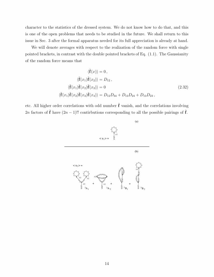
etc. Finally we express the generating functional Z(l,m), with the help of Eq.(4.20), in the
form of a functional integral:
Z(l,m) =1
Z
∫Du(x)Dp(x) (4.31)
× exp{iI +
∫dx[u(x) · l(x) + p(x) ·m(x)]
}.
The quantity I is referred to as the effective action, and for future work it is useful to divide
into two parts, the one quadratic and the other triadic in the field p and u:
I = I0 + Iint , (4.32)
I0 =∫dx[pα∂uα∂t− ν pα∇2uα
]
+i
2
∫pα(x)Dαβ(x− y)pβ(y)dxdy , (4.33)
Iint = −i∫dx pα(x)uβ(x)∂βuα(x) (4.34)
=1
2
∫dq1dq2dq3
(2π)12pαΓαβγ(q, q1, q2)uβ(q2)uγ(q3)
The last line follows from the definition of the vertex in the q representation, see Eq. (2.22).
Note that we did not display a transverse projector in the expression of Iint. The reason is
that the definition (4.6) restricts anyway the integration to divergenceless fields.
Finally, we introduce also the bare generating functional which is (4.31) when I = I0,
Z0(l,m) =1
Z0
∫Du(x)Dp (4.35)
× exp{iI0 +
∫dx[u(x) · I(x) + p(x) ·m(x)]
}
This bare generating functional is used in the formulation of the perturbative expansion.
We will first use it to evaluate the bare propagators.
C. The evaluation of the bare propagators
It is convenient to change the variables in I0 from p(x) and u(x) to p(k, ω) and u(k, ω),
which are defined according to Eq. (2.19). The Jacobian of the transformation (which is
formally a divergent constant) cancels with the partition sum:
I0 =∫
dq
(2π)4pα(q)[−iω + νk2]uα(−q)
+1
2
∫ dq
(2π)4pα(q)Dαβ(q)pβ(−q) (4.36)
38

where we remind the reader that q ≡ (k, ω).
The bare propagators are computed from Z0(l,m) which in this presentation is written
as
Z0(l,m) =1
Z0
∫Du(q)Dp(q) (4.37)
× exp{iI0 +
∫dq
(2π)4[u(q) · l(−q) + p(q) ·m(−q)]
}.
This functional integral can be computed explicitly. Since we have no mixture of different
q’s in the exponent, the exponential can be computed (on the grid) as the product of
exponentials. The functional integration is represented as a product of integrals, each one
for one discrete q and −q:∫Du(q) =
∏
q>0
∫du(q)du(−q) .
Computing the resulting Gaussian integrals, and using the expression of the bare Green’s
function (2.16), we end up with
Z0(l,m) (4.38)
= exp{ ∫ dq
(2π)4
[12lα(−q)G0
αβ(q)Dβγ(q)G0∗γδ(q)lδ(−q)
+ G0αβ(q)lα(−q)mβ(−q)
]}.
We can check that this zeroth order generating functional gives the same results as the
zeroth order quantities defined in the direct perturbation theory. In computing the statistical
quantities from (4.38) we use the general property of functional differentiation
δlα(q)
δlβ(q′)= (2π)4δ(q − q′)δαβ . (4.39)
and the symmetry of the bare Green’s function G0αβ(q) = −G0∗
αβ(−q) [cf. Eq.(2.16)]. For
example, defining the velocity correlation function in q-representation, Fαβ(q), according to
〈uα(q)uβ(q′)〉 = (2π)4δ(q + q′)Fαβ(q) , (4.40)
we compute its bare value 〈uα(q)uβ(q′)〉0 as
〈uα(q)uβ(q′)〉0 =δ2Z0(l,m)
δlα(−q)δlβ(−q′). (4.41)
In other words, we find
39

F 0αβ(q) = G0
αγ(q)Dγδ(q)G∗δβ(q) . (4.42)
Similarly, defining the Green’s function in q-representation as
(2π)4δ(q + q′)Gαβ(q)
= iδ〈uα(q)〉δhβ(q′)
∣∣∣∣∣h→0
= 〈uα(q)pβ(q′)〉 . (4.43)
Since
〈uα(q)pβ(q′)〉0 =δ2Z0(l,m)
δmα(−q)δlβ(−q′), (4.44)
we get trivially that
〈uα(q)pβ(q′)〉0 = (2π)4δ(q + q′)G0αβ(q) .
We see that this theory generates the same zeroth order propagators as the direct per-
turbation expansion of Section II. Note however that there exists an apparent additional
propagator here which is absent in II, which is 〈pα(q)pβ(q′)〉. However, the zeroth order
〈pα(q)pβ(q′)〉0 is zero. This follows from the fact that Z0(l,m) does not have a term quadratic
in m in the exponent. We shall show later that it is zero to all orders.
Next we show that the statistics inherited from Z0(l,m) are Gaussian statistics. The
exponent contained in Z0(l,m) can be expanded as
Z0(l,m) = 1 +∫
dq
(2π)4
[12lα(−q)F 0
αβ(q)lβ(q)lβ(−q)
+lα(−q)G0αβ(q)mβ(−q)
](4.45)
+1
2
{ ∫ dq
(2π)4
[12lα(−q)F 0
αβ(q)lβ(−q)
+ lα(−q)G0αβ(q)mβ(−q)
]}2
+ . . .
+1
n!
{ ∫dq
(2π)4
[12lα(−q)F 0
αβ(q)lβ(−q)
+ lα(−q)G0αβ(q)mβ(−q)
]}n+ . . .
Clearly, if we take an odd number of derivatives with respect to lα, and then send l and m
to zero, the result vanishes. On the other hand, if we take 2n derivatives, and then send l
and m to zero, only the contributions coming from the n-th power of the integral survive.
The answer will be proportional to [F 0]n with n delta functions. The number of terms will
be 2n!/[n!2n] which is precisely the (2n − 1)!! number of terms expected in the Gaussian
statistics (cf. Sect. II C). Note that we have Gaussian statistics also for the field p.
40

Instead of looking at the correlation functions, one can study the cumulants. These of
course need to vanish beyond the lowest order. An immediate way to obtain the cumulants
is to take functional derivatives of ln Z0(l,m) instead of Z0(l,m) itself. Obviously,
lnZ0(l,m) =∫
dq
(2π)4(4.46)
×[12lα(−q)F 0
αβ(q)lβ(−q) + lα(−q)G0αβ(q)mβ(−q)] .
Only the second derivative with respect to l survives here, giving us only the bare 2-point
propagators F 0αβ and G0
αβ as the non-vanishing cumulants, as is required for Gaussian statis-
tics.
1/2G = + < +x x'
x<
12
12
x x1 2
12
12
12
12
x'
(a)
x 1 x 2 x 3 x 4
x1 x2
x x'A
x x'B
(b)
+
12
12 1
2
x1
x3 x4
x x' x x'C D
12
x1 x2+
x3 x4
x 4x 3
x x x x'1 2
E
+
+
(c)
+ 4!1
>
>
G =∆ 2x2
x2
1/2 1/2
1/21/21/21/2
1/2
1/2 1/2
1/2
G =∆ 4
FIG. 12. The graphic representation of Eq.(4.50). Panel (a): The bare, the second order and
the fourth order terms. Panel (b): All the diagrams up to order Γ2 and (c) representative diagrams
of order Γ4 that did not appear in the Wyld diagrammatic series in Fig. 5. All these new diagrams
vanish.
41
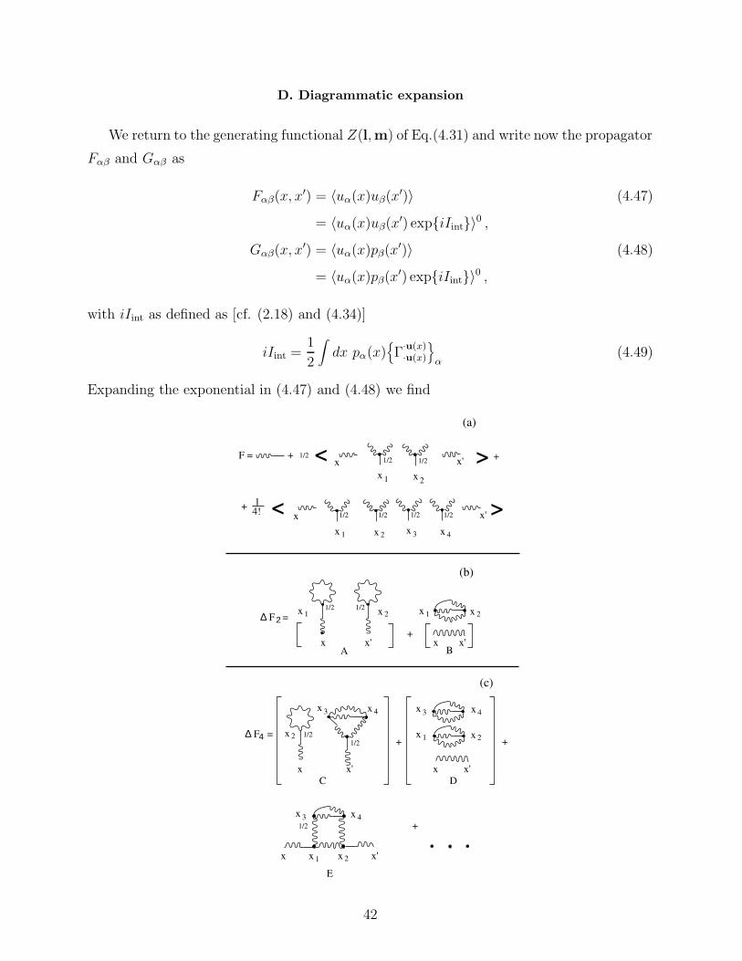
D. Diagrammatic expansion
We return to the generating functional Z(l,m) of Eq.(4.31) and write now the propagator
Fαβ and Gαβ as
Fαβ(x, x′) = 〈uα(x)uβ(x′)〉 (4.47)
= 〈uα(x)uβ(x′) exp{iIint}〉0 ,Gαβ(x, x′) = 〈uα(x)pβ(x′)〉 (4.48)
= 〈uα(x)pβ(x′) exp{iIint}〉0 ,
with iIint as defined as [cf. (2.18) and (4.34)]
iIint =1
2
∫dx pα(x)
{Γ·u(x)·u(x)
}α
(4.49)
Expanding the exponential in (4.47) and (4.48) we find
F = + < +x x'
x<
x x1 2
>
>x'
(a)
x x'A
x x'B
(b)
+
x x' x x'C D
+
x x'
E
+
+
(c)
>
>
x 1 x 2
x 2x 1x 1 x 2
x 3 x 4
x 3 x 4
x 1 x 2
x 3 x 4
x 2
x 3 x 4
x 1 x 2
1/21/2 1/2
1/21/21/21/2
1/2 1/2
1/21/2
1/2
F =∆ 2
F =∆ 4
+ 4!1
42

FIG. 13. The graphic representation of Eq.(4.51). Panel (a): The bare, the second order and
the fourth order terms. Panel (b): All the diagrams up to order Γ2 and representative diagrams of
order Γ4 that did not appear in the Wyld diagrammatic series in Fig. 6. All these new diagrams
vanish.
Gαβ(x, x′) =∑
n
1
n!
⟨uα(x)pβ(x′)
×{1
2
∫dx pα(x)
[Γ·u(x)·u(x)
]α
}n⟩0, (4.50)
Fαβ(x, x) =∑
n
1
n!
⟨uα(x)pβ(x)
×{1
2
∫dx pα(x)
[Γ·u(x)·u(x)
]α
}n⟩0, (4.51)
Such an expansion contains products of the fields u and p averaged over the Gaussian en-
semble. As explained above, only products of 〈uα(x)pβ(x′)〉0 and 〈uα(x)uβ(x′)〉0 can appear
in such a series. (Remember that 〈pα(x)pβ(x′)〉0 = 0). As done in chapter II, the procedure
of computing the averages can be represented diagrammatically by pairing all the allowed
pairs of fields and gluing. The needed graphic notation is the same as the one shown in
Fig. 1. The field u is represented by a short wavy line, the field p by a short straight line,
and now it is obvious why the double correlator is represented by a twice long wavy line.
Also, the notation for the Green’s function becomes natural now, being a correlator of u
and p. In addition, the notation for the vertex as a dot connecting one straight and two
wavy tails becomes apparent in Eqs.(4.50) and (4.51).
The diagrams that are obtained from Eqs.(4.50) and (4.51) are shown in Figs. 12a and
13a respectively. Upon pairing all the possible pairs and gluing, we get exactly the diagrams
appearing in Figs. 5a and 6a respectively, and in addition we get the diagrams appearing
in panels b and c of Figs. 12 and 13. These additional diagrams, that are denoted here
as ∆G2, ∆G4, ∆F2 and ∆F4 respectively, do not appear in the diagrammatic expansion
leading to Figs. 5 and 6. However, it is easy to see that they are all zero. The diagram
A in 12b contains one term which is a diagram for 〈u〉 and another one which represents
a contribution to 〈p〉. The latter contains a frequency integral over G0, which is −i/2.
However the vertex Γ in front of this contains a factor of k which is odd in the k-integration.
Therefore the diagram vanishes. The diagrams B, C, D and E in 12b,c contain closed loops
of Green’s functions. Such loops vanish because of causality: in t-representation only t = 0
is allowed for the Green’s function in a closed loop, and thus the integral over time has a
contribution only from a single point, and it vanishes.
43

Next we argue that this phenomenon is general: all the diagrams that do not appear
in Wyld’s expansion are zero. These diagrams are either unlinked (like all the diagrams in
Fig. 12 except for E) or linked to the body via wavy lines (like E). All these diagrams must
have a closed loop of Green’s functions. Consider a diagram from the n-th order, in which
m vertices, m ≤ n, form a fragment that is unlinked to the body. Glue the straight line of
the first vertex to the wavy line of another. Then either we close the straight line of the
second vertex on the wavy line, or we connect it to a wavy line of a third vertex. The first
possibility leads to zero due to the argument of diagram A in 12b. In the second possibility
we again need to repeat the same option, or to closed with the first vertex. The production
of a close loop of Green’s functions is inevitable, and these vanish due to causality. Diagrams
that are connected only via wavy lines also must have a closed loop of Green’s functions for
the same reasons.
We thus conclude that the path integral formulation leads to exactly the same diagrams
as the Wyld direct perturbative expansion. This fact is not widely recognized. One reason
for this is that in Ref. [9] the three types of vertices which appear in this theory were not
explictly discussed. They were first dealt with properly in [10] in which it was stated that
the results agree with [9] only to order Γ3. We have shown above that the two techniques
generate exactly the same (non-zero) diagrams on the naive level, and these can be resummed
in exactly the same way. For example, Fig. 6 of Ref [21] was claimed to differ from the Wyld
technique, but in fact is identical to the present Fig. 10b which was obtained entirely within
the Wyld expansion.
5. SUGGESTIONS FOR FURTHER READING
The material presented in these notes should be sufficient to prepare the student for
reading the research papers on the subject of renormalized perturbation theory of turbulence.
For the convenience of the interested student we present in this section a brief guided tour
through the latest publications of our own group. The next paper to read is [16] in which the
Belinicher-L’vov renormalization scheme is used to prove that the theory for the correlation
functions and the Green’s functions is finite. In other words, it is shown (order by order)
that for Re→ ∞, after the appropriate resummations, all the diagrams converge both in
the IR and the UV limits. This fact tells us that there is no length scale available to
form dimensionless corrections to the K41 scaling. In [19] the issue of anomalous scaling is
discussed. It is shown that there exist anomalous exponents in turbulence, but they appear
44

in gradient fields and their correlations. Thus for example the dissipation field is anomalous,
and its correlation function is strongly renormalized compared with the Gaussian limit. The
issue of the effect of the anomalous fields on the structure functions was discussed in [20]. It is
argued there that the anomalous fields are subcritical, and that they influence the structure
functions only on the level of corrections to scaling. The latter corrections are large, and
they disappear only at very large values of Re. We attributed the observed deviations in
experiments to these “subciritcal” corrections. Two more papers that may be considered
are [22] and [23] in which further relations to experiments are discussed. In [23] we discuss
which length scale should be used as the renormalization scale in turbulence, i.e the inner
scale η or the outer scale L. In [22] one can find an experimental test of some aspects of the
new theory, especially some unusual correlation functions between velocity differences and
the dissipation field.
ACKNOWLEDGMENTS
We thank Adrienne Fairhall and Volodia Lebedev for their comments on the manuscript.
This work has been supported in part by the German-Israeli Foundation and the N. Bronicki
fund.
6. APPENDIX: THE JACOBIAN
In this appendix we explain the known fact [17,18] that the Jacobian that appears in
Eq.(4.10) is unity. From the definition of the delta function it is obvious that
∫Du(x)δ[u(x)−N−1{f(x)}] = 1 . (6.1)
This means that also the functional integral over the RHS of Eq.(4.10) is unity. What we
want to prove now is that also the functional integral on the RHS of (4.10) without J{u} is
unity:
∫Du(x)δ[N{u(x)} − f (x)] = 1 . (6.2)
This will be the first indication that the Jacobian J{u} = 1. To accomplish this we will
only use the fact that the Navier-Stokes equations are first order in the time derivative:
N{u(x)} =∂u(x)
∂t+ NL{u(x)} . (6.3)
45

The time derivative on the time grid may be represented in the retarded convention
∂un(r)
∂tn= [un(r)− un−1(r)]/τ . (6.4)
Using this representation we rewrite (6.2) on the time grid as
∫ ∏
n
Dun(r)δ[un(r) + NL{un−1(r)}] . (6.5)
We have collected everything except un itself into an operator that was denoted as NL. It
is obvious now that every Dun(r) integration yields unity due to the delta function, and
finally the result is unity. Next one should prove that the functional integrals (6.1) and
(6.2) but with any arbitrary weight functional of u are also the same. Repeating the same
considerations on the time grid furnishes this demonstration with essentially the same ease.
46

REFERENCES
∗ L’vov’s e-mail: [email protected].
† Procaccia’s e-mail: [email protected].
[1] L.F. Richardson. Weather Prediction by Numeric Process. Cambridge Univ. Press, Cam-
bridge, 1922.
[2] Lewis F. Richardson. Atmospheric diffusion shown on a distance neighbor graph. Proc.
R. Soc. Lond. A, 110:709–737, 1926.
[3] A. S. Monin and A. M. Yaglom. Statistical Fluid Mechanics: Mechanics of Turbulence,
volume II. The MIT Press, Cambridge, Mass., 1973.
[4] A. N. Kolmogoroff. uber das logarithmisch normale Verteilungsgesetz dd Dimensionen
der Teilchen bei Zerztckelungg. C. R. (Doklady) Acad. Sc. URSS, 31:99–101, 1941.
[5] Uriel Frisch. Turbulence: The Legacy of A.N. Kolmogorov. Cambridge University Press,
Cambridge, 1995. In press.
[6] K.R. Sreenivasan and P. Kailasnath. An update on the intermittency exponent in tur-
bulence. Phys. Fluids A, 5(2):512–514, 1993.
[7] R.H. Kraichnan. The structure of isotropic turbulence at very high Reynolds numbers.
J. Fluid Mech., 5:497–543, 1959.
[8] S. A. Orszag. Analytical theories of turbulence. J. Fluid Mech., 41:363–386, 1970.
[9] H. W. Wyld. Formulation of the theory of turbulence in an incompressible fluid.
Ann. Phys., 14:143–165, 1961.
[10] P. C. Martin, E. D. Siggia, and H. A. Rose. Statistical dynamics of classical systems.
Phys. Rev. A, 8(1):423–437, July 1973.
[11] V. E. Zakharov and V. S. L’vov. On statistical description of the nonlinear wave fields.
Quan. Electronics, 18(10):1084–1097, 1975.
[12] R. H. Kraichnan. Lagrangian-history closure approximation for turbulence. Phys. Fluids,
8:575–598, 1965.
[13] R.H. Kraichnan. Isotropic turbulence and inertial-range structure. Phys. Fluids, 9:1728–
1752.
47

[14] V. I. Belinicher and V. S. L’vov. A scale-invariant theory of fully developed hydrody-
namic turbulence. Sov. Phys. JETP, 66:303–313, 1987.
[15] V. S. L’vov. Scale invariant theory of fully developed turbulence. Hamiltonian approach.
Phys. Rep., 207(1):1–47, August 1991.
[16] V. S. L’vov and I. Procaccia. Exact resummations in the theory of hydrodynamic tur-
bulence. I. The ball of locality and normal scaling. Phys. Rev. E, 1995. Submitted.
[17] C. DeDominics. J. Physique (Paris), 37:C1–247, 1976.
[18] H.K. Jansen. Z. Phys. B, 23:377, 1976.
[19] V. S. L’vov and I. Procaccia. Exact resummations in the theory of hydrodynamic tur-
bulence. II. A ladder to anomalous scaling. Phys. Rev. E, 1995. Submitted.
[20] V. S. L’vov and I. Procaccia. “Intermittency” in turbulence as intermediate asymptotics
to Kolmogorov’41 scaling. Phys. Rev. Lett., 1995. Submitted, E-print in Los-Alamos e-
board No 9410002 (1994) [email protected] .
[21] V. S. L’vov and V. V. Lebedev. Exact relations in the theory of fully developed hydro-
dynamic turbulence. Phys. Rev. E, 47(4):1794–1802, 1993.
[22] V. S. L’vov and I. Procaccia. Correlator of velocity differences and energy dissipation as
element in the subcritical scenario for nonKolmogorov scaling in turbulence. Europhys.
Lett., 1995. In press.
[23] V.S. L’vov and I. Procaccia. Is the fundamental length scale in developed turbulence
the inner or the outer scale ? Phys. Rev. E, 1995. Submitted
48