articulated robot -ra620 c08ue001-1803 3. warnings 3.1 common safety issues all operating procedures...
TRANSCRIPT

www.hiwin.tw
User Manual
Articulated Robot -RA620

INDUSTRIE 4.0 Best Partner
Multi Axis RobotPick-and-place / Assembly / Array and packaging / Semiconductor / Electro-Optical industry / Automotive industry / Food industry• Articulated Robot• Delta Robot• SCARA Robot• Wafer Robot• Electric Gripper • Integrated Electric Gripper• Rotary Joint
Single Axis RobotPrecision / Semiconductor /Medical / FPD• KK, SK• KS, KA • KU, KE, KC
Direct Drive Rotary TableAerospace / Medical / Automotive industry / Machine tools / Machinery industry• RAB Series• RAS Series• RCV Series• RCH Series
BallscrewPrecision Ground / Rolled• Super S series• Super T series• Mini Roller• Ecological & Economical
lubrication Module E2• Rotating Nut (R1)• Energy-Saving & Thermal-
Controlling (C1)• Heavy Load Series (RD) • Ball Spline
Linear GuidewayAutomation / Semiconductor / Medical• Ball Type--HG, EG, WE, MG, CG• Quiet Type--QH, QE, QW, QR• Other--RG, E2, PG, SE, RC
Medical EquipmentHospital / Rehabilitation centers /Nursing homes• Robotic Gait Training System• Hygiene System• Robotic Endoscope Holder
BearingMachine tools / Robot• Crossed Roller Bearings • Ball Screw Bearings • Linear Bearing• Support Unit
AC Servo Motor & DriveSemiconductor / Packaging machine /SMT / Food industry / LCD• Drives-D1, D1-N, D2 • Motors-50W~2000W
Driven Tool HoldersAll kinds of turret • VDI Systems
Radial Series, Axial Series, MT • BMT Systems
DS, NM, GW, FO, MT, OM, MS
Linear MotorAutomated transport / AOI application / Precision / Semiconductor• Iron-core Linear Motor• Coreless Linear Motor • Linear Turbo Motor LMT • Planar Servo Motor • Air Bearing Platform• X-Y Stage • Gantry Systems
Torque Motor (Direct Drive Motor)Inspection / Testing equipment / Machine tools / Robot• Rotary Tables-TMS,TMY,TMN• TMRW Series• TMRI Series
1
C08UE001-1803
Safety Precautions
1. Safety Information
Safety Responsibility & Effect
This chapter explains how to use the robot safely. Be sure to read this
chapter carefully before using the robot.
The user of the HIWIN industrial robot has responsibility to design and
install the safety device meeting the industrial safety regulations in order
to ensure personal safety.
2. Description Related to Safety
I. Safety Symbols
Carefully read the instructions in the user manual prior to robot use. The
safety symbols used by this user manual are listed as follows.
Symbol Description
Failure to follow instructions with this symbol may result
in serious hazard or personal injury. Please be sure to
comply with these instructions.
Failure to follow instructions with this symbol may result
in personal injury or product damage. Please be sure to
comply with these instructions.
Failure to follow instructions with this symbol may result
in poor product performance. Please be sure to comply
with these instructions.
II. Working Person
The personnel can be classified as follows
Operator:
Turns robot controller power ON/OFF
Starts robot program from operator`s panel
Programmer or teaching operator:
Operates the robot
Teaches robot inside the safety fence
Maintenance engineer:
Operates the robot
Teaches robot inside the safety fence
Maintenance, adjustment, replacement
Programmer and the maintenance engineer must be trained on proper
robot operation

2
C08UE001-1803
3. Warnings
3.1 Common Safety Issues
All operating procedures should be established
by professional assessment and in compliance
with related industrial safety regulations.
When operating robot, operator needs to wear
safety equipment, such as smock for working
environment, safety shoes and helmets.
When encountering danger or other emergency or
abnormal situation, please press the emergency
stop button immediately and move the arm away
with lower speed in manual mode.
When considering the safety of the robot, the
robot and the system must be considered together.
Be sure to install safety fence or other safety
equipment, the operator must be outside the safety
fence to operate the robot.
A safety zone should be established around the
robot with an appropriate safety device to limit
access of unauthorized personnel.
Ensure the workpiece weight does not exceed the
rated load or the tolerable torque. Exceeding
these values could lead to the driver alarms or
arm malfunction.
Personnel operating robot should be trained and
licensed.
To ensure personal safety, robot installation must
comply with this manual and related industrial
safety regulations.
The control cabinet should not be placed near
high voltage or machines that generate
electromagnetic fields to prevent interference
that could cause the robot to deviate or
malfunction.
Use of non-OEM repair parts may cause robot
damage or malfunction.
Beware high temperature generated by the
controller and servo motor.
3
C08UE001-1803
Do not over bend the cable to avoid poor
circuit contact.
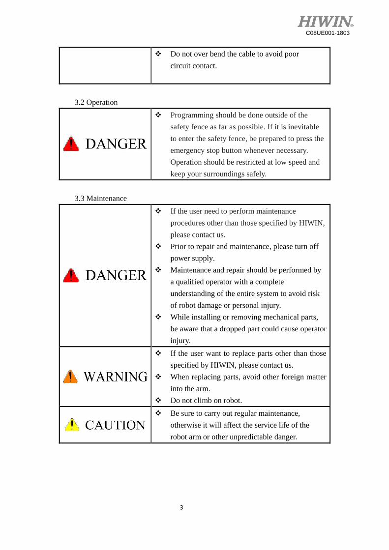
3.2 Operation
Programming should be done outside of the
safety fence as far as possible. If it is inevitable
to enter the safety fence, be prepared to press the
emergency stop button whenever necessary.
Operation should be restricted at low speed and
keep your surroundings safely.
3.3 Maintenance
If the user need to perform maintenance
procedures other than those specified by HIWIN,
please contact us.
Prior to repair and maintenance, please turn off
power supply.
Maintenance and repair should be performed by
a qualified operator with a complete
understanding of the entire system to avoid risk
of robot damage or personal injury.
While installing or removing mechanical parts,
be aware that a dropped part could cause operator
injury.
If the user want to replace parts other than those
specified by HIWIN, please contact us.
When replacing parts, avoid other foreign matter
into the arm.
Do not climb on robot.
Be sure to carry out regular maintenance,
otherwise it will affect the service life of the
robot arm or other unpredictable danger.
4
C08UE001-1803
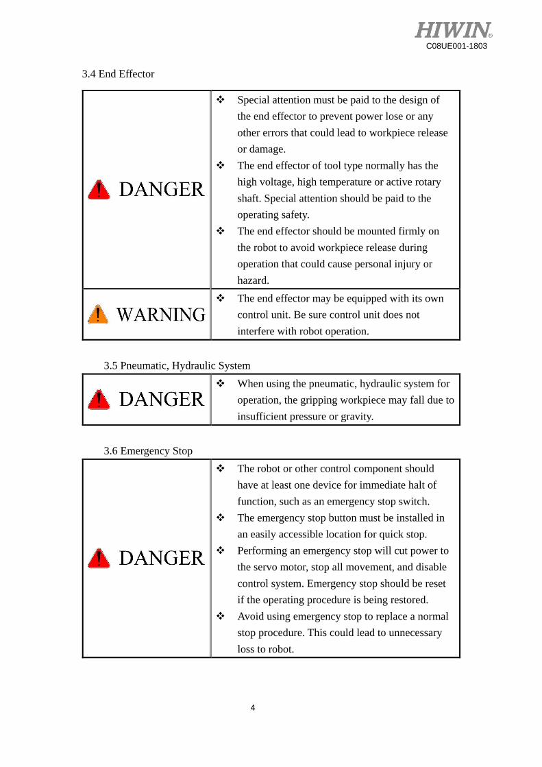
3.4 End Effector
Special attention must be paid to the design of
the end effector to prevent power lose or any
other errors that could lead to workpiece release
or damage.
The end effector of tool type normally has the
high voltage, high temperature or active rotary
shaft. Special attention should be paid to the
operating safety.
The end effector should be mounted firmly on
the robot to avoid workpiece release during
operation that could cause personal injury or
hazard.
The end effector may be equipped with its own
control unit. Be sure control unit does not
interfere with robot operation.
3.5 Pneumatic, Hydraulic System
When using the pneumatic, hydraulic system for
operation, the gripping workpiece may fall due to
insufficient pressure or gravity.
3.6 Emergency Stop
The robot or other control component should
have at least one device for immediate halt of
function, such as an emergency stop switch.
The emergency stop button must be installed in
an easily accessible location for quick stop.
Performing an emergency stop will cut power to
the servo motor, stop all movement, and disable
control system. Emergency stop should be reset
if the operating procedure is being restored.
Avoid using emergency stop to replace a normal
stop procedure. This could lead to unnecessary
loss to robot.

5
C08UE001-1803
Table of Contents
1. Transport and Installation………………………………………………….. 7
1.1 Transport .................................................................................................... 7
1.2 Installation.................................................................................................. 9
1.3 Connection with the Controller ................................................................ 11
1.4 Grounding ................................................................................................ 13
1.5 Operating Ambient Conditions ................................................................ 13
1.6 Standard and Optional Equipment List .................................................... 14
2. Basic Specifications……………………………………………………….15
2.1 Description of Serial Number .................................................................. 15
2.2 Labels ....................................................................................................... 16
2.3 Robot Specifications ................................................................................ 17
2.4 Outer Dimensions and Motion Range...................................................... 19
2.5 Wrist Load conditions .............................................................................. 21
3. Equipment Mounting Surface and Interface ……………………………..23
3.1 Mounting surface for end effector ........................................................... 23
3.2 Mounting Surface on the robot arm ......................................................... 23
3.3 Interface for Air supply ............................................................................ 25
3.4 I/O Interface ............................................................................................. 26
4. Calibration…………………………………………………………………30
4.1 Resetting Zero Position ............................................................................ 30
5. Maintenance and Check …………………………………………………..35
5.1 Periodic Inspection Items ......................................................................... 35
5.2 Maintenance ............................................................................................. 38
6
C08UE001-1803
5.2.1 Backup Batteries Replacement ........................................................... 38
5.2.2 Timing Belt Replacement ................................................................... 39
5.2.3 Grease Replenishment ........................................................................ 44
Edition Date Model Remark
C08UC001-1711 2017.11.14 RA620 First edition

7
C08UE001-1803
1. Transport and Installation
1.1 Transport
The transportation of the robot can use lifting tackle or forklift truck. The transportation
procedure is as follows:
Step1. The angle of each joint is shown in the table of Figure 1-2 and 1-3.
Step2. Attach the suspension frame to the robot, as shown in Figure 1-1. When carrying the
robot with lifting tackle, four M8×1.25P eye bolt, M8 nuts and M8 washers should be
mounted on the suspension frame.
Step3. Move the robot to the desired position by lifting tackle or forklift truck.
Step4. Remove the suspension frame.
Transport by forklift truck Transport by forklift tackle
Figure 1-1 Transportation
Before carrying the robot, be sure to remove the end
effector. That will cause center of gravity changes.
Please always stay in stable condition and avoid
excessive vibration or shock during transportation.
Placing the robot be sure to avoid the robot and the
installation surface collision.
After removing the suspension frame, please maintain
it properly for re-transportation.
Before operation, remove the suspension frame to
avoid damage to the robot.

8
C08UE001-1803
Figure 1-2 Transport position(RA620-1621)
Figure 1-3Transport position(RA620-1739)
Transport position
J1 0°
J2 35°
J3 -70°
J4 0°
J5 -55°
J6 0°
Transport position
J1 0°
J2 35°
J3 -70°
J4 0°
J5 -55°
J6 0°
Center of gravity Center of gravity
Weight of the robot: 226 kg
Center of gravity Center of gravity
Weight of robot: 230 kg

9
C08UE001-1803
1.2 Installation
Figure 1-4 shows the installation dimensions of the robot. According to the dimensions, fix
the robot with installation bolt (M16 Grade 12.9) on the installation surface. Figure 1-5 and
Table 1-1 show the forces and moments acting on the installation surface. The installation
surface must have sufficient strength to withstand the dynamic movement of the robot when
operating at maximum speed.
Figure1-4 Installation dimension
Figure 1-5 Forces and moments acting on the installation surface

10
C08UE001-1803
Table 1-1 Value of forces and moments acting on the installation surface
Ensure the installation surface has been leveled. It is
recommended the roughness on this surface be 6.3a or
less. If the installation surface is rough, the robot could
produce the position shift during the operation.
Ensure the position of the installation surface for the
robot will not shift owing to the movement.
Ensure the strength of the installation surface for the
robot will not damage owing to the movement.
Vertical moment
MV (Nm)
Vertical force
FV (N)
Horizontal
moment
MH (Nm)
Horizontal force
FH (N)
Stop 1550 2352 0 0
Acceleration
/Deceleration 5114 5718 2735 4148

11
C08UE001-1803
1.3 Connection with the Controller
Figure 1-6 shows the structure drawing of the robot. Figure 1-7 shows overview of the robot
system. A robot system comprises the robot, the controller, CN2 connecting cable, and the teach
pendant. The connection for the motor and air in/out are located at the rear of the J1 base, as
shown in Figure 1-8. The pin assignment of the connection for the motor is shown in Table 1-2.
Figure 1-6 structure drawing of the robot
Figure 1-7 Illustration of robot and controller installation
Teach pendant
Controller
Robot
Main power

12
C08UE001-1803
Figure 1-8 Interface at the rear of J1 base
Table 1-2 Pin assignment of the CN2
When connecting the cable, be sure to turn off power
supply first.
13
C08UE001-1803
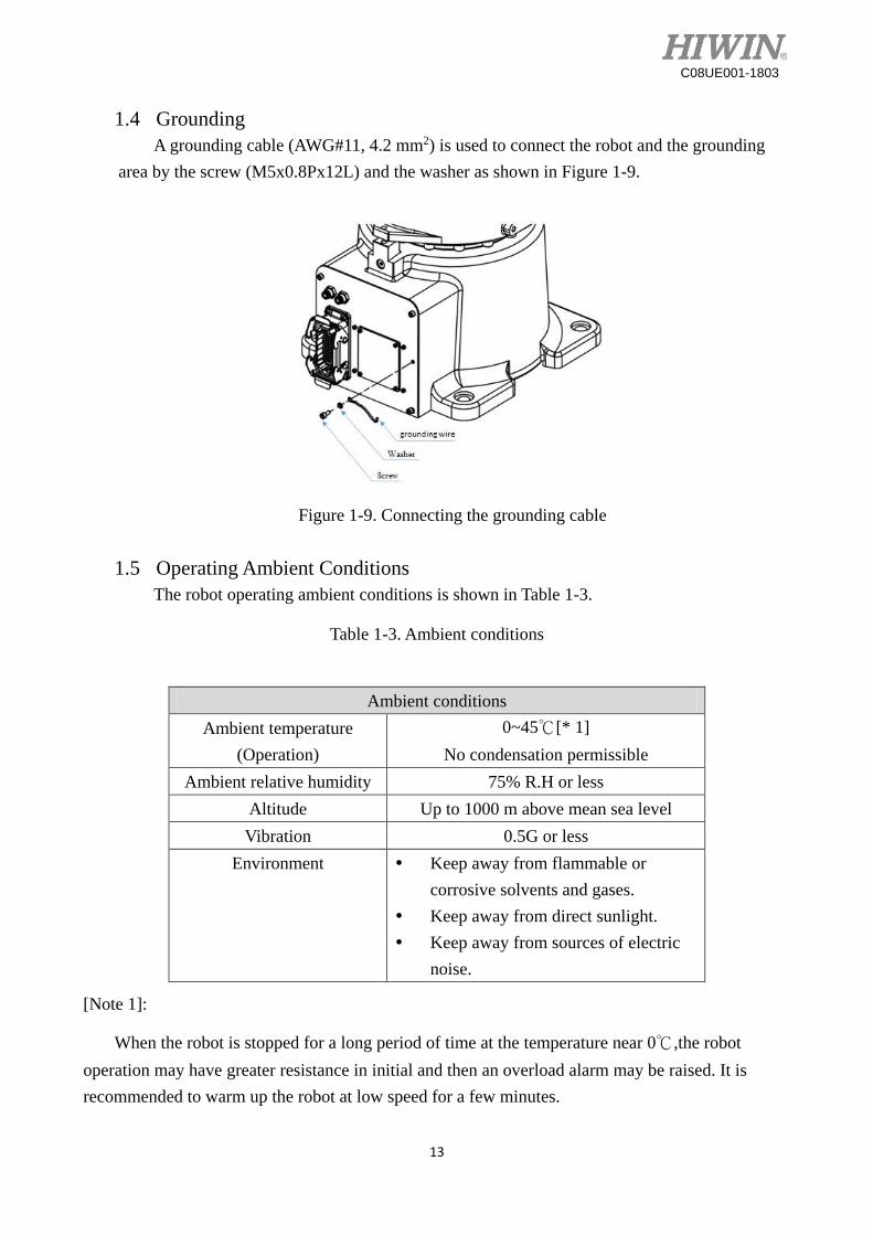
1.4 Grounding
A grounding cable (AWG#11, 4.2 mm2) is used to connect the robot and the grounding
area by the screw (M5x0.8Px12L) and the washer as shown in Figure 1-9.
Figure 1-9. Connecting the grounding cable
1.5 Operating Ambient Conditions
The robot operating ambient conditions is shown in Table 1-3.
Table 1-3. Ambient conditions
[Note 1]:
When the robot is stopped for a long period of time at the temperature near 0℃,the robot
operation may have greater resistance in initial and then an overload alarm may be raised. It is
recommended to warm up the robot at low speed for a few minutes.
Ambient conditions
Ambient temperature
(Operation)
0~45℃[* 1]
No condensation permissible
Ambient relative humidity 75% R.H or less
Altitude Up to 1000 m above mean sea level
Vibration 0.5G or less
Environment Keep away from flammable or
corrosive solvents and gases.
Keep away from direct sunlight.
Keep away from sources of electric
noise.

14
C08UE001-1803
1.6 Standard and Optional Equipment List
Standard and optional equipment list is shown in Table 1-4 and 1-5.
Table 1-4 Standard equipment list
Table 1-5 Optional equipment list
Item Part No. Remarks
Lithium battery 462600LN Refer to section 5.2.1
Timing belt
505-5GT-9 453100SR
Refer to section 5.2.2
(RA620-1739)
Timing belt
540-5GT-9 4531012N
Refer to section 5.2.2
(RA620-1621)
End effector straight
connector with 1.5m cable 4C7015J1
End effector right angle
connector with 1.5m cable 4C7015K1
J1~J4 Lubrication grease 47110042 Refer to section 5.2.3
J5~J6 Lubrication grease 47110035 Refer to section 5.2.3
Item Part No. Remark
RA620 Calibration tool set 4C201K01 Refer to section 4.1
Suspension frame set 4C200WS3 Refer to section 1.1
End effector I/O connector 4CA30008 Refer to section 3.4

15
C08UE001-1803
2. Basic Specifications
2.1 Description of Serial Number
The robot have a serial number on the rear of J1 base, and the explanation of serial
number is shown in Figure 2-1.
Figure 2-1 Description of serial number

16
C08UE001-1803
2.2 Labels
The labels on the robot arm is shown in Table 2-1.
Table 2-1 Labels description
Labels Name Description
Collision
Keep safety distance from robot system,
and prevent colliding to operator during
operation.
Grounding
Make sure grounding is completed, or it
will cause electric shock.
Transport
Be aware of transport position when
transporting robot, please refer to section 1-
1 for detailed information.
Specificati
on
Robot specification and serial number
Air in
The connection port of air tube for air input.
Air out
The connection port of air tube for air out.
Grease in
The hole for grease in.
Grease out
The hole for grease out.

17
C08UE001-1803
2.3 Robot Specifications
The robot specifications are as shown in Table 2-2
Table 2-2 The robot specifications
Item Specification
Model No. RA620-1739 RA620-1621
Degrees of Freedom 6
Installation Floor
(wall mounting, ceiling mounting) [*1]
Load capacity 20kg [*2] 30kg[*2]
Maximum reach radius 1739 mm 1621mm
Cycle time 0.9 s [*3]
Position Repeatability ±0.06 mm
Motion range
J1 ±180°
J2 +100°~-135°
J3 +190°~-80°
J4 ±200°
J5 ±130°
J6 ±360°
Maximum speed
J1 231°/ s
J2 210°/ s
J3 205°/ s
J4 360°/ s
J5 420°/ s 210°/ s
J6 720°/ s 360°/ s
Allowable load
moment at wrist
J4 34.2 N-m 65.5 N-m
J5 34.2 N-m 65.5 N-m
J6 22.3 N-m 34 N-m
Allowable load
inertia at wrist
J4 1.35 kg- m2 4.71 kg- m2
J5 1.35 kg- m2 4.71 kg- m2
J6 0.6 kg- m2 1.49 kg- m2
Weight 230 kg 226 kg
Protection rating Wrist(J5~J6) :IP65, Arm(J1~J4): IP54
Acoustic noise level Less than 75 dBA [*4]

18
C08UE001-1803
[Note 1]:The robot arm motion range shall be defined when used by mounting on the wall.
So that the end effector does not interfere with the rear side of robot arm when mounting on
the wall.
[Note 2]:When installing the end effector, please refer to section 2.5.
[Note 3]:The cycle time is the time that the robot is loaded at 20kg to forward and backward
move in the vertical height 25mm and the horizontal distance 30mm, as shown in Figure 2-2.
Figure 2-2 Moving path for cycle time
[Note 4]:This is measured at maximum speed and maximum load according to
ISO11201:2010.

19
C08UE001-1803
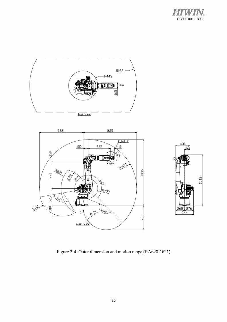
2.4 Outer Dimensions and Motion Range
The outer dimensions and motion range are shown in Figure 2-3 and 2-4.
Figure 2-3. Outer dimension and motion range (RA620-1739)
20
C08UE001-1803
Figure 2-4. Outer dimension and motion range (RA620-1621)

21
C08UE001-1803
2.5 Wrist Load conditions
The rated load of the robot end is not only limited by the weight but also limited by
the position of the center of gravity of the load, where Figure 2-5 and 2-6 show the
allowed position of the center of gravity.
Figure 2-5. Wrist load diagram (RA620-1739)

22
C08UE001-1803
Figure 2-6. Wrist load diagram (RA620-1621)

23
C08UE001-1803
3. Equipment Mounting Surface and Interface
3.1 Mounting surface for end effector
The mounting surface for end effector on the wrist end is shown in Figure 3-1.
Figure 3-1. Mounting surface for end effector (RA620-1739 and RA620-1621)
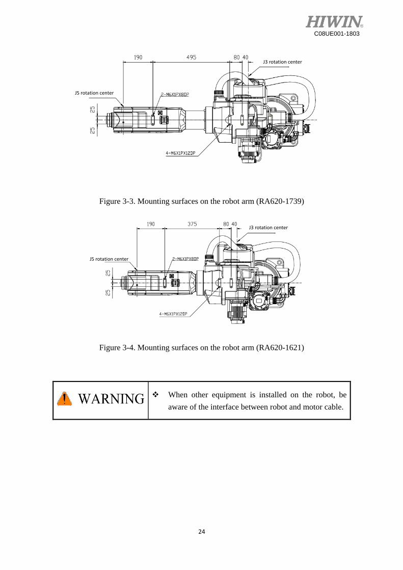
3.2 Mounting Surface on the robot arm
Mounting surfaces for the peripheral equipment are shown in Figure 3-2~3-4.
Figure 3-2. Mounting surfaces on the robot arm (RA620-1739 and RA620-1621)
24
C08UE001-1803
Figure 3-3. Mounting surfaces on the robot arm (RA620-1739)
Figure 3-4. Mounting surfaces on the robot arm (RA620-1621)
When other equipment is installed on the robot, be
aware of the interface between robot and motor cable.
J3 rotation center
J5 rotation center
J3 rotation center
J5 rotation center
25
C08UE001-1803
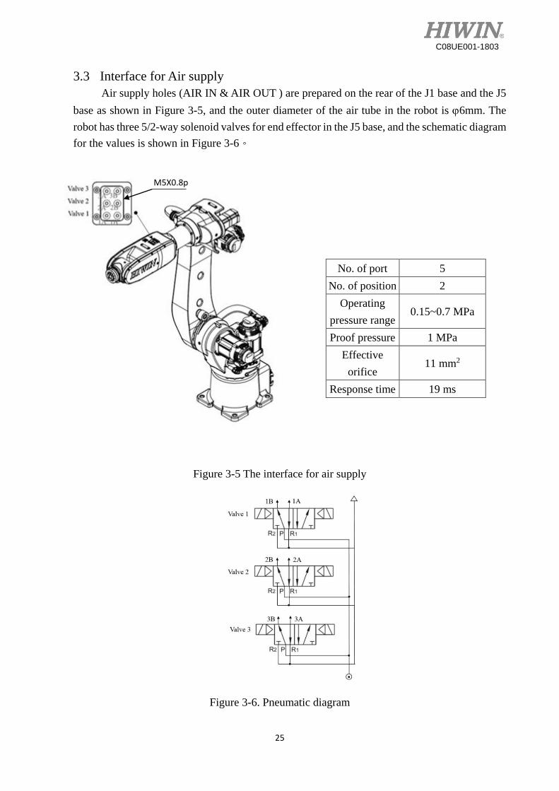
3.3 Interface for Air supply
Air supply holes (AIR IN & AIR OUT ) are prepared on the rear of the J1 base and the J5
base as shown in Figure 3-5, and the outer diameter of the air tube in the robot is 6mm. The
robot has three 5/2-way solenoid valves for end effector in the J5 base, and the schematic diagram
for the values is shown in Figure 3-6。
Figure 3-5 The interface for air supply
Figure 3-6. Pneumatic diagram
No. of port 5
No. of position 2
Operating
pressure range 0.15~0.7 MPa
Proof pressure 1 MPa
Effective
orifice 11 mm2
Response time 19 ms
M5X0.8p

26
C08UE001-1803
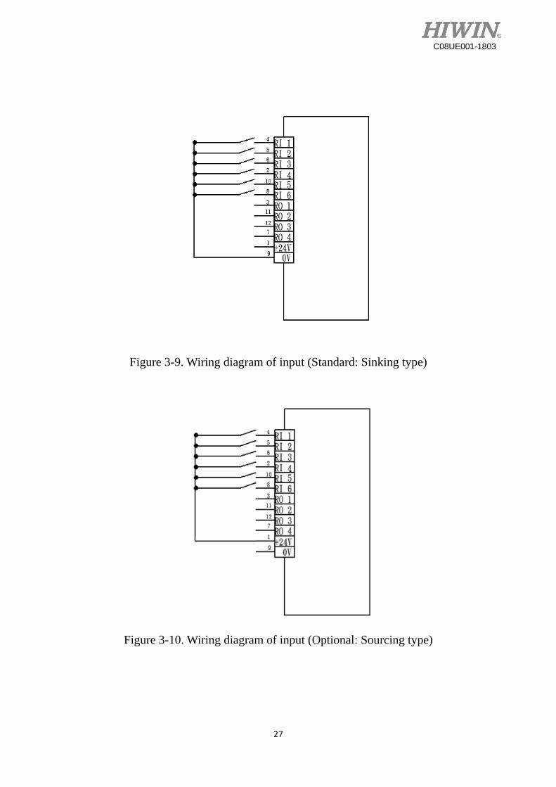
3.4 I/O Interface
I/O interface for end effector is on the J5 base as shown in Figure 3-7, and the pin assignment
of I/O connector for user is shown in Figure 3-8. Figure 3-9 ~ 3-12 shows the wiring diagram of
I/O interface.
Figure 3-7. I/O interface for end effector
Figure 3-8 Pin definition of the I/O plug
(Power output: 24V/1A)
27
C08UE001-1803
Figure 3-9. Wiring diagram of input (Standard: Sinking type)
Figure 3-10. Wiring diagram of input (Optional: Sourcing type)

28
C08UE001-1803
Figure 3-11. Wiring diagram of input (Standard: Sinking type)
Figure 3-12. Wiring diagram of output (Optional: Sourcing type)
Pin 1 and 9 are used for signal, not for input power of
end effector.
The maximum current at each pin is 100mA.

29
C08UE001-1803
When operating robot, the cable of end effector might be tangled together with the robot.
Fixing a cable-tie-fix-seat on the J5 base by using the screw (M6×1P), and secure the cable of end
effector I/O connector as Figure 3-13.
Figure 3-13. Fixing method for the cable of the end effector I/O connector
Cable
Cable tie fix seat
End effector I/O connector

30
C08UE001-1803
4. Calibration
4.1 Resetting Zero Position
The calibration tools for resetting zero position are shown in Figure 4-1. When reset zero
position, operate the robot at low speed and move the robot to align the calibration tool with the
pinhole.The robot is adjusted to the minimum speed during the calibration, and aligns the
pinhole with the calibration tool to set up the original position. The procedure of resetting
zero position with the calibration tools is shown in Figure 4-1 below.
4-1(a) 4-1(b) 4-1(c) 4-1(d)
J1~3 J4 J5 J6
Figure 4-1. The calibration tool set
J1-axis zero position setting
Step1: Operate J1 at low speed to align the pinhole of J2 base with the pinhole of J1 base.
Step2: Insert the calibration tool for J1~3 to the pinhole to calibrate zero position.
Step3: Complete the calibration and remove the calibration tool.
Step4: Clear encoder by HRSS. (Refer to page 34)
Step5: Resetting zero position of J1 axis is completed.
Figure 4-2 Illustration of J1-axis zero position setting

31
C08UE001-1803
J2-axis zero position setting
Step1: Operate J2 at low speed to align the pinhole of J3 base with the pinhole of J1 base.
Step2: Insert the calibration tool for J1~3 to the pinhole to calibrate zero position.
Step3: Complete the calibration and remove the calibration tool.
Step4: Clear encoder by HRSS. (Refer to page 34)
Step5: Resetting zero position of J2-axis is completed.
Figure 4-3 Illustration of J2-axis zero position setting
J3-axis zero position setting
Step1: Operate J3 at low speed to align the pinhole of J4 base with the pinhole of J3 base.
Step2: Insert the calibration tool for J1~3 to the pinhole to calibrate zero position.
Step3: Complete the calibration and remove the calibration tool.
Step4: Clear encoder by HRSS. (Refer to page 34)
Step5: Resetting zero position of J3-axis is completed.
Figure 4-4 Illustration of J3-axis zero position setting

32
C08UE001-1803
J4-axis zero position setting
Step1: Operate J4 at low speed to align the keyway of J5 base with the keyway of J4 base.
Step2: Insert the calibration tool for J4 to the keyway to calibrate zero position.
Step3: Complete the calibration and remove the calibration tool.
Step4: Clear encoder by HRSS. (Refer to page 34)
Step5: Resetting zero position of J4-axis is completed.
Figure 4-5 Illustration of J4-axis zero position setting
J5 -axis zero position setting
Step1: Operate J5 at low speed to align the pinhole of J6 base with the pinhole of J5 base.
Step2: Insert the calibration tool for J5 to the pinhole to calibrate zero position.
Step3: Complete the calibration and remove the calibration tool.
Step4: Clear encoder by HRSS. (Refer to page 34)
Step5: Resetting zero position of J5 -axis is completed.
Figure 4-6Illustration of J5-axis zero position setting

33
C08UE001-1803
J6-axis zero position setting
Step1: Operate J6 at low speed to align the keyway of EE with the keyway of J6 base.
Step2: Insert the calibration tool for J6 to the keyway to calibrate zero position.
(Old design reference to Figure 4-7(b), align the calibration mark with the keyway.)
Step3: Complete the calibration and remove the calibration tool.
Step4: Clear encoder by HRSS. (Refer to page 34)
Step5: Resetting zero position of J6-axis is completed.
4-7(a) 4-7(b)
Figure 4-7 Illustration of J6 -axis zero position setting
Mark for calibration
Calibration tool for J4

34
C08UE001-1803
Clear encoder by HRSS
Step1: Select the “JOINT” as the coordinate system.
Step2: Move the robot to the zero position. (Refer to section 4-1)
Step3: Click Main Menu>>Start-up>>Master>>Clear Encoder. (As shown in Figure 4-8)
Step4: Double click the -axis to clear encoder. (As shown in Figure 4-8)
Figure 4-8 Clear encoder by HRSS

35
C08UE001-1803
5. Maintenance and Check
This chapter will introduce the maintenance and periodical inspection procedures to maintain
the robot for a reasonable service life. It includes the cover removal and installation, inspection and
replacement of the timing belt, lubrication position, the procedures for replacing the battery, and other
notes.
[Note 1] The operating time of the robot is defined as 3840 hours per year. When using the robot
beyond this operating time, correct the maintenance frequencies shown in this chapter by
calculation in proportion to the difference between the actual operating time and 3840 hours per
year.
5.1 Periodic Inspection Items
The daily inspection items before the robot operation are shown in Table 5-1.
Table 5-1 Daily Inspection Items
Inspection item Remedies
Before turning power ON
1 機 Are any of the robot installation screws,
cover installation screws and end effector
installation screws loose?
Securely tighten the screws.
2 Are any of cables securely connected?
Such as the power and signal cable,
grounding cable, the cable for teach
pendant and the cable between the robot
and other equipment.
Securely connect.
3 Is the pneumatic system normal? Are there
any air leaks, drain clogging or hose
damage? Is there air source normal?
Drain the drainage and replace the leaks part.
After turning power ON
1 Check whether the robot moves smoothly
without vibration or noise.
1. The robot installation screws might not be
securely fastened to the installation surface.
Securely tighten the screws.
2. If the roughness of the installation surface
is uneven, modify the installation surface
to the reasonable surface roughness.
3. The base might not be sufficiently rigid.
Please reinforce the base to make it more
rigid.
4. There might have foreign material between
the robot and the installation surface. Please

36
C08UE001-1803
remove it.
5. Some operating positions might be too
demanding for the robot mechanism, please
adjust the load, speed or acceralation.
Please reduce load or acceleration.
6. The timing belt might loosen or not in
correct location. Please replace or adjust the
timing belt. (Refer to section 5.2.2)
7. If the grease of the reducer has not been
changed for a long period. Please change
the grease. (Refer to section 5.2.3)
8. If the bearing or the reducer has damage on
the rolling surface or the gear tooth surface.
Please contact HIWIN direcly.
2 The repeatability is not within the
tolerance.
1. The zero position of the robot might be
rewritten. Please reset the zero position.
(Refer to section 4.1)
2. If the repeatability is unstable, repair the
robot by referring to the descriptions of
unusual vibration and noise above.
Table 5-2 Periodic inspection items
Inspection item Remedies
Inspection item A (1 month / 320 hours)
1 Clean and check each part of the robot. Check if there are any cracks and flows on the
robot.
Inspection item B (3 months / 960 hours)
1 Check the ventilation portion of the
controller.
If it is dusty, turn off the power and clean the
ventilation portion of the controller
Inspection item C (6 months / 1920 hours)
1 Check whether the timing belt is
abnormal.
Adjust the tension of the timing belt. If the
friction at the timing belt is severe, replace it.
Refer to section 5.2.2.
Inspection item D (1year / 3840 hours)
1 Replace the backup battery in the
robot.
Replace the backup battery. Refer to section
5.2.1
Inspection item E (3years/11520hours)

37
C08UE001-1803
1 Change the lubrication grease of the
reducer.
Change the grease. Refer to section 5.2.3.
Table 5-3 Inspection schedule
In the initial operation, it is normal that the timing
belt has some friction. If the rubber appear soon
after cleaning it, please wipe them again and replace
the belt.

38
C08UE001-1803
5.2 Maintenance
5.2.1 Backup Batteries Replacement
The absolute encoder of the motor is used to record the position of the robot. When the
controller power turn off, the position data of each -axis is preserved by the backup batteries.
The batteries are installed when the robot is shipped from the factory. If the batteries are in use,
the annual change of batteries is needed. The service life of the batteries depends on the operating
conditions of the robot. In order to avoid the loss of position data, the batteries need to be
changed by the user periodically. The procedure for replacing the batteries of the robot is shown
in Figure 5-1. The procedures are described as below.
Step1. Ensure the robot and controller are connected with the cables.
Step2. Keep the power on. Press the emergency stop button to prohibit the movement of the
robot motion.
Step3. The battery box is located in the rear of the J1 base. Please remove the battery cover.
Step4. Replace the battery one by one. If all batteries are removed in the same time, the position
data will be lost. Therefore, please resetting the robot to the zero position.
Step5. After replacing the battery, ensure to install the battery cover.
Figure 5-1. The backup batteries replacement
All batteries should be changed simultaneously. If
the old batteries are included, the service life of the
batteries may be reduced.
39
C08UE001-1803
5.2.2 Timing Belt Replacement
The robot uses the timing belt for the driver system of the J5 and J6 -axis. Although the belt
tension has been adjusted before the robot is shipped, the timing belt will wear depending on the
robot working conditions. The belt tension might be lower than the standard over a long time
operation. The timing belt should be periodically checked, maintained and replaced.
Timing Belt replacement period
Check the timing belt for about 6 months. The timing belt must be replaced if the belt teeth is
found cracks, wear to approximately half of the tooth width, or break.
Timing Belt replacement period
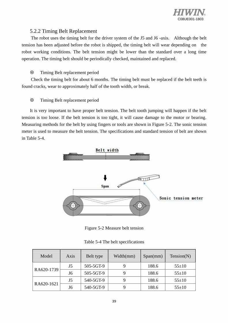
It is very important to have proper belt tension. The belt tooth jumping will happen if the belt
tension is too loose. If the belt tension is too tight, it will cause damage to the motor or bearing.
Measuring methods for the belt by using fingers or tools are shown in Figure 5-2. The sonic tension
meter is used to measure the belt tension. The specifications and standard tension of belt are shown
in Table 5-4.
Figure 5-2 Measure belt tension
Table 5-4 The belt specifications
Model Axis Belt type Width(mm) Span(mm) Tension(N)
RA620-1739 J5 505-5GT-9 9 188.6 55±10
J6 505-5GT-9 9 188.6 55±10
RA620-1621 J5 540-5GT-9 9 188.6 55±10
J6 540-5GT-9 9 188.6 55±10
40
C08UE001-1803
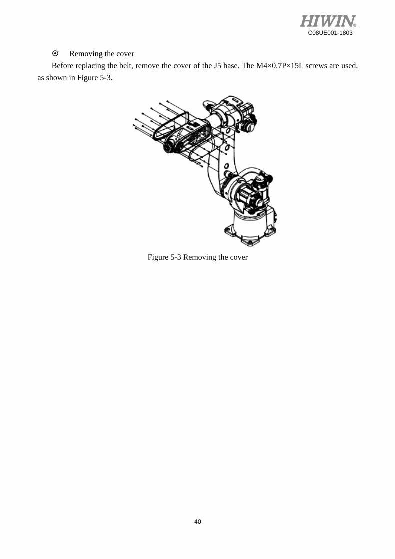
Removing the cover
Before replacing the belt, remove the cover of the J5 base. The M4×0.7P×15L screws are used,
as shown in Figure 5-3.
Figure 5-3 Removing the cover

41
C08UE001-1803
Inspection, maintenance and replacement of timing belt in J5 -axis.
Figure 5-4 J5 -axis structure diagram (RA620-1739)
Figure 5-5 J5 -axis structure diagram (RA620-1621)
Inspect J5 -axis timing belt
Step1. Ensure the power of controller be switched off.
Step2. Remove the cover of the J5 base.
Step3. Check whether the timing belt is normal.
Step4. If the timing belt is abnormal, refer to the following paragraph to replace the
timing belt.
Step5. If the belt tension is lower than the standard, refer the following paragraph to
adjust the belt tension.
Adjust J5 -axis timing belt
Step1. Loose the two motor plate fixing screws, so that the motor can be moved.
Step2. Refer to Table 5-4, turn the adjusting screw to adjust the tension of the belt.
Step3. Tighten the two motor plate fixing screws(4.6 N-m).
Pulley
Belt
Tension screw Fixing screw Pulley
Pulley
Belt
Tension screw Fixing screw Pulley

42
C08UE001-1803
Replacing J5 -axis timing belt
Step1. Remove the two motor plate fixing screws.
Step2. Loose the adjusting screw to replace the timing belt.
Step3. After replacing the belt, refer to the paragraph “Adjusting J5 -axis timing belt”
above to adjust the tension of the belt.
Inspection, maintenance and replacement of J6 -axis timing belt
Figure 5-6 J6 -axis structure diagram
Figure 5-6 J6 -axis structure diagram
Inspect J6 -axis timing belt
Step1. Confirm that the controller power is OFF. Ensure the power of controller be
switched off.
Step2. Remove the cover of the J6 base.
Step3. Check whether the timing belt is normal.
Step4. If the timing belt is abnormal, refer to the following paragraph to replace the
timing belt.
Belt wheel Belt wheel Belt
Tension screw Fixing screw
Belt wheel Belt wheel Belt
Tension screw Fixing screw

43
C08UE001-1803
Step5. If the belt tension is lower than the standard, refer the following paragraph to
adjust the belt tension.
Adjusting J6 -axis timing belt
Step1. Loose the two motor plate fixing screws, so that the motor can be moved.
Step2. Refer to Table 5-5, turn the adjusting screw to adjust the tension of the belt.
Step3. Tighten the two motor plate fixing screws. (4.6 N-m)
Replacing J6 -axis timing belt
Step1. Remove the two motor plate fixing screws.
Step2. Loose the adjusting screw to replace the timing belt.
Step3. After replacing the belt, refer to the paragraph “Adjusting J6 -axis timing belt”
above to adjust the tension of the belt.

44
C08UE001-1803
5.2.3 Grease Replenishment
The grease inlets and the air vents are shown in Figure 5-6.
Figure 5-6 Lubrication and air inlet/outlet positions
Grease specification
Table 5-5 Grease specification
Part name Grease
nipple Lubrication grease Quantity
Lubrication
interval
J1 reduction gear M8 VIGOGREASE REO 1405 ml
11520Hr
J2 reduction gear M8 VIGOGREASE REO 745 ml
J3 reduction gear M8 VIGOGREASE REO 350 ml
J4 reduction gear M8 VIGOGREASE REO 265 ml
J5 reduction gear M5 SK-1A 18 ml
J6 reduction gear M5 SK-1A 33 ml
[Note1]:If the robot is not used for 2 years, replace the grease of each axis.
[Note2]:The J5 cover needs to be removed for J5 grease replacing.

45
C08UE001-1803
Procedure of grease replenishment
Step1. The grease inlets and the air vents of the robot are shown in Figure 5-6.
Step2. Remove the screw of the grease inlet, and install the grease nipple.
Step3. Remove the screw of the air vent.
Step4. Replenish the grease from the grease inlet by the grease gun.
Step5. Install the screw of the air vent.
Step6. Remove the grease nipple, and install the screw of the grease inlet.
Figure 5-7 Grease replenishment

1. HIWIN is the registered trademark of HIWIN Technologies Corp.. For your protection; To avoid counterfeit products, be certain you are buying genuine HIWIN products before purchase.
2. Actual products may be different from the specifications and photos in this catalog. The differences in appearances or specifications may be caused by, among other things, product improvements.
3. HIWIN will not sell or export those techniques and products restricted under the "Foreign Trade Act" and relevant regulations. Any export of restricted products should be approved by competent authorities in accordance with relevant laws, and shall not be used to manufacture or develop nuclear, biochemical, missile and other military weapons.
4. HIWIN website for patented product directory: http://www.hiwin.tw/Products/Products_patents.aspx
Publication Date:March 2018, first edition
Articulated Robot - RA620 User Manual
Copyright © HIWIN Technologies Corp.

Copyright © HIWIN Technologies Corp.©2018 FORM C08UE001-1803 (PRINTED IN TAIWAN)The specifications in this catalog are subject to change without notification.
Subsidiaries & R&D Centers
HIWIN Schweiz GmbHJONA, [email protected]
HIWIN s.r.o.BRNO, CZECH [email protected]
HIWIN [email protected]
HIWIN KOREASUWON‧MASAN, [email protected]
HIWIN CHINASUZHOU, [email protected]
Mega-Fabs Motion System, Ltd.HAIFA, [email protected]
HIWIN GmbHOFFENBURG, [email protected]
HIWIN JAPANKOBE‧TOKYO‧NAGOYA‧NAGANO‧TOHOKU‧SHIZUOKA.HOKURIKU‧HIROSHIMA‧FUKUOKA‧KUMAMOTO, [email protected]
HIWIN USACHICAGO‧SILICON VALLEY, U.S.A. [email protected]
HIWIN SrlBRUGHERIO, [email protected]
HIWIN TECHNOLOGIES CORP.No. 7, Jingke Road, Taichung Precision Machinery Park,Taichung 40852, TaiwanTel: +886-4-23594510Fax: [email protected]