articles - csaglobal.com · the description of any “obvious ... provides a non-destructive way to...
TRANSCRIPT

Volume 58 ~ Number TWO ~ JUNE 2015
31 geobulletin JUNE 2015
AR
TIC
LE
S
The current edition of the SAMREC Code for public
reporting of Exploration Results, Mineral Resources
and Ore Reserves includes Table 1 which is a high-
level checklist of assessment and reporting criteria.
Although not prescriptive, it is important for the
Competent Person (“CP”) to “report all matters that
might materially affect a reader’s understanding or
interpretation of the results or estimates being reported”
(SAMREC, page 28). The Code goes further and states
that the CP has the responsibility to consider all criteria
listed and which additional criteria should apply to the
particular project.
The author’s intention is to address some of the criteria
listed under ‘Treatment / Processing’ of Section 5.5 of
SAMREC Table 1 and to provide examples from graphite
exploration projects related to the issue of flake size
and liberation characteristics. These criteria include
the description of any “obvious processing factors that
could have a significant effect on the prospects of any
possible exploration target or deposit” and “the basis
for assumptions or predictions regarding metallurgical
amenability and any preliminary metallurgical test
work”.
Given that industrial minerals such as graphite are
normally produced and sold according to size, purity
and / or performance specifications, the responsibility
falls on the CP to ensure that samples are tested for
appropriate parameters such as flake size and purity,
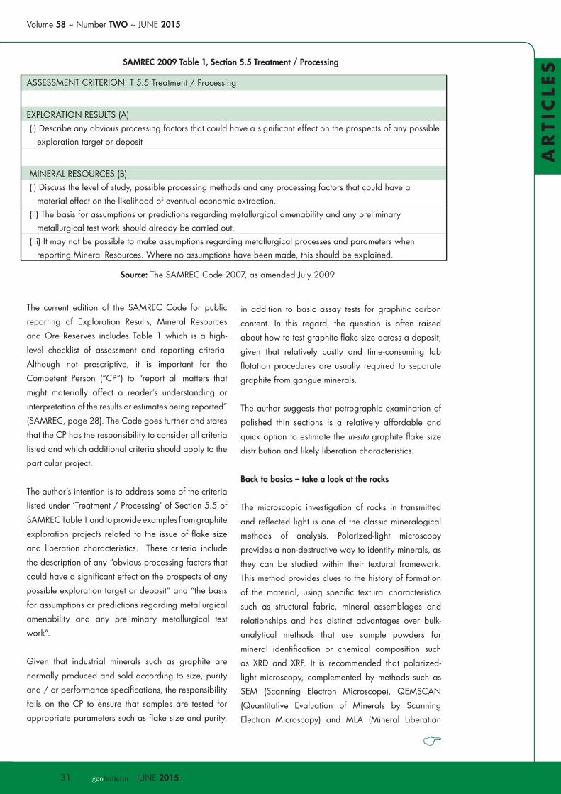
ASSESSMENT CRITERION: T 5.5 Treatment / Processing
EXPLORATION RESULTS (A) (i) Describe any obvious processing factors that could have a significant effect on the prospects of any possible
exploration target or deposit
MINERAL RESOURCES (B)(i) Discuss the level of study, possible processing methods and any processing factors that could have a
material effect on the likelihood of eventual economic extraction.(ii) The basis for assumptions or predictions regarding metallurgical amenability and any preliminary
metallurgical test work should already be carried out.(iii) It may not be possible to make assumptions regarding metallurgical processes and parameters when
reporting Mineral Resources. Where no assumptions have been made, this should be explained.
SAMREC 2009 Table 1, Section 5.5 Treatment / Processing
Source: The SAMREC Code 2007, as amended July 2009
in addition to basic assay tests for graphitic carbon
content. In this regard, the question is often raised
about how to test graphite flake size across a deposit;
given that relatively costly and time-consuming lab
flotation procedures are usually required to separate
graphite from gangue minerals.
The author suggests that petrographic examination of
polished thin sections is a relatively affordable and
quick option to estimate the in-situ graphite flake size
distribution and likely liberation characteristics.
Back to basics – take a look at the rocks
The microscopic investigation of rocks in transmitted
and reflected light is one of the classic mineralogical
methods of analysis. Polarized-light microscopy
provides a non-destructive way to identify minerals, as
they can be studied within their textural framework.
This method provides clues to the history of formation
of the material, using specific textural characteristics
such as structural fabric, mineral assemblages and
relationships and has distinct advantages over bulk-
analytical methods that use sample powders for
mineral identification or chemical composition such
as XRD and XRF. It is recommended that polarized-
light microscopy, complemented by methods such as
SEM (Scanning Electron Microscope), QEMSCAN
(Quantitative Evaluation of Minerals by Scanning
Electron Microscopy) and MLA (Mineral Liberation

32 geobulletin JUNE 2015
Maggie Lambert-Newman
Dinosaurs
Volume 58 ~ Number TWO ~ JUNE 2015
33 geobulletin JUNE 2015
34 geobulletin JUNE 2015
AR
TIC
LE
S
Analyser, or automated SEM) should be used when
evaluating a graphite project.
Graphite explorers are encouraged to ‘get back to
basics’ and use thin section petrography as a primary
tool to evaluate and compare prospective targets
(Scogings, 2015). Thin section petrography helps with
the geometallurgical domaining of graphite deposits
and selection of composites for metallurgical testing,
in addition to explaining subsequent metallurgical test
results.
Geometallurgy is multi-disciplinary approach that
combines geology and mineralogy with extractive
metallurgy, to create a predictive model that assists with
selecting appropriate mineral processing for a deposit.
It is used to reduce risk during mineral processing plant
design and can also assist with production scheduling.
Mining and processing based solely on grade (e.g.
graphite content) may not be sufficient, as seemingly
low grade mineralisation may result in a high quality
concentrate if processed appropriately.
There are several steps that may be used in developing
a geometallurgical model for a graphite deposit,
including:
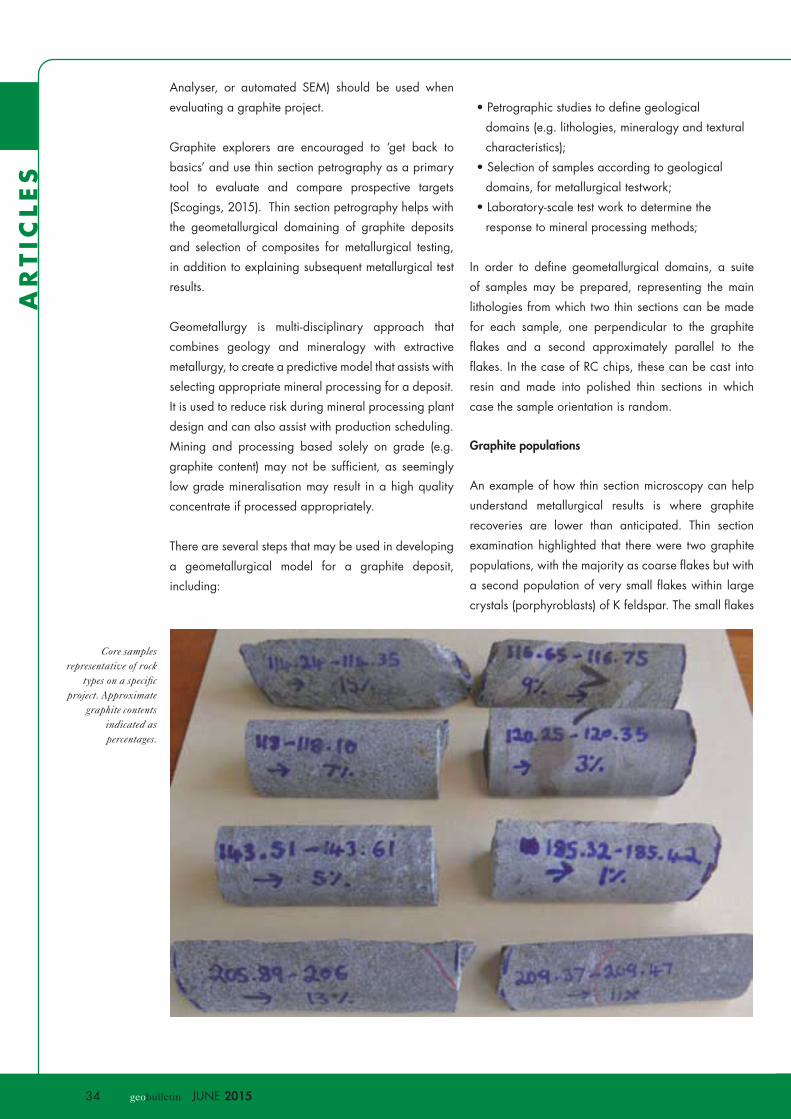
Core samples representative of rock
types on a specific project. Approximate
graphite contents indicated as percentages.
• Petrographic studies to define geological
domains (e.g. lithologies, mineralogy and textural
characteristics);
• Selection of samples according to geological
domains, for metallurgical testwork;
• Laboratory-scale test work to determine the
response to mineral processing methods;
In order to define geometallurgical domains, a suite
of samples may be prepared, representing the main
lithologies from which two thin sections can be made
for each sample, one perpendicular to the graphite
flakes and a second approximately parallel to the
flakes. In the case of RC chips, these can be cast into
resin and made into polished thin sections in which
case the sample orientation is random.
Graphite populations
An example of how thin section microscopy can help
understand metallurgical results is where graphite
recoveries are lower than anticipated. Thin section
examination highlighted that there were two graphite
populations, with the majority as coarse flakes but with
a second population of very small flakes within large
crystals (porphyroblasts) of K feldspar. The small flakes
Volume 58 ~ Number TWO ~ JUNE 2015
35 geobulletin JUNE 2015
AR
TIC
LE
S
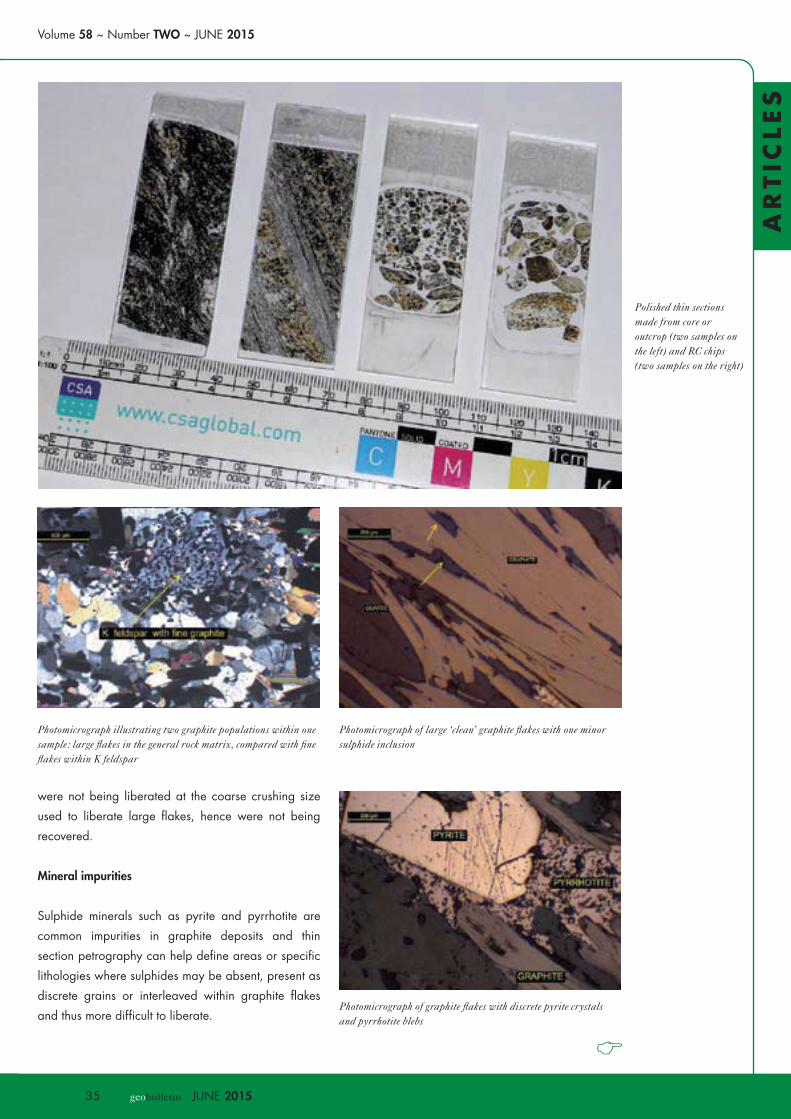
Polished thin sections made from core or outcrop (two samples on the left) and RC chips (two samples on the right)
Photomicrograph illustrating two graphite populations within one sample: large flakes in the general rock matrix, compared with fine flakes within K feldspar
Photomicrograph of large ‘clean’ graphite flakes with one minor sulphide inclusion
were not being liberated at the coarse crushing size
used to liberate large flakes, hence were not being
recovered.
Mineral impurities
Sulphide minerals such as pyrite and pyrrhotite are
common impurities in graphite deposits and thin
section petrography can help define areas or specific
lithologies where sulphides may be absent, present as
discrete grains or interleaved within graphite flakes
and thus more difficult to liberate. Photomicrograph of graphite flakes with discrete pyrite crystals and pyrrhotite blebs
36 geobulletin JUNE 2015
AR
TIC
LE
S
Flake size
A second example of the benefits of thin section
petrography may be where flake size varies across
an individual deposit, or between prospects within
a region and where the explorer wishes to select an
appropriate target. In this particular case, the explorer
identified one target as having a population of very
small flakes in a retrograde sericitic assemblage and a
second target as containing coarse flakes in a medium
to high grade metamorphic assemblage and elected to
follow up on the second target.
Conclusions and recommendations
• Graphite explorers are urged to ‘get back to basics’
and use thin section petrography as a basic tool
to help address treatment / processing aspects of
industrial mineral resources according to SAMREC
2009 requirements.
• It is suggested that petrographic examination of
polished thin sections be done early on in the project
and during the subsequent resource drilling phase.
Polished thin sections are relatively inexpensive and
can be used to estimate the size and shape of in-situ
graphite flake populations, relationships with other
minerals including contaminants such as sulphide
minerals, and for estimating likely liberation size.
However it should be borne in mind that in situ flake
size estimations don’t necessarily translate directly to
flake sizes produced by metallurgical processes such
as gravity separation or froth flotation.
• Core drilling is the preferred technique for graphite
exploration, as this provides undisturbed samples
for thin sections and for metallurgical tests. Reverse
Circulation (RC) drill chips may also be used to make
thin sections; however RC chips are not suitable for
metallurgical tests due to the grinding action of the
drill bit, which reduces flake size. Caution should
be exercised when selecting RC chips, as there may
have been preferential grinding of softer (possibly
graphite-rich) rocks.
•Once appropriate metallurgical samples have been
selected, some cost-effective and fairly quick tests
such as i) assay by size and ii) heavy liquid separation
Photomicrograph of pyrrhotite interleaved along cleavage planes in graphite
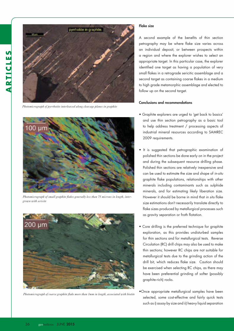
Photomicrograph of small graphite flakes generally less than 75 microns in length, inter-grown with sericite
Photomicrograph of coarse graphite flake more than 1mm in length, associated with biotite