article publié par le laboratoire de construction en béton ... · bond-slip relationship...
TRANSCRIPT

Article publié par le Laboratoire de Construction en Béton de l'EPFL Paper published by the Structural Concrete Laboratory of EPFL
Article publié par le Laboratoire de Construction en Béton de l'EPFL Paper published by the Structural Concrete Laboratory of EPFL
Title: Influence of geometric, strain and size effects on bond in structural concrete
Authors: Muttoni A., Fernández Ruiz M.
Published in: Bond in Concrete 2012
Pages: pp. 15-21
City, country: Brescia, Italy
Year of publication: 2012
Type of publication: Peer reviewed conference paper
Please quote as: Muttoni A., Fernández Ruiz M., Influence of geometric, strain and size effects onbond in structural concrete, Bond in Concrete 2012, Brescia, Italy, 2012, pp.15-21.
[Muttoni12b] Downloaded by infoscience (http://help-infoscience.epfl.ch/about) 128.178.209.23 on 15.10.2012 11:18

15
1 INTRODUCTION
Bond is an instrumental mechanism in structural concrete, allowing the transfer of forces between concrete and reinforcement bars or tendons. It thus governs many phenomena from first loading (crack-ing, tension–stiffening) to failure (lap splices, ductil-ity). Bond is activated under various actions (pure tension, pull–out, push–in...) and may develop vari-ous failure modes (shearing of concrete between ribs, splitting failures…). Its behaviour depends on a wide set of geometrical parameters (short/long em-bedment-length, small/large concrete cover, small/large bar diameter ...) as well as on mechanical parameters of reinforcing bars (elastic and hardening moduli, yield strength ...) and of the concrete (com-pressive and tensile strength...). Also, structural con-text (defining for instance the confinement level) play a significant role. Although research on bond is as ancient as structural concrete itself and some con-sistent mechanical explanations have been provided to explain its features, most design expressions are still based on empirical approaches. Research works summarizing current knowledge and design models can be consulted elsewhere (fib 2000, fib, 2012).
In 2010, first complete draft of Model Code 2010 (fib 2010a,b) was published, constituting a state-of-the-art design approach with respect to bond. The design provisions given in MC2010 cover most sig-nificant influences known in bond. They are ex-
plained and thoroughly grounded in a specific doc-ument (fib, 2012) providing justification of the fail-ure modes considered and how are they accounted for. In spite of the fact that the expressions are in-spired on mechanical analogies, the design formulas and constitutive laws are still empirical. They have been derived through consideation of governing pa-rameters and by fitting of them through available test data.
According to MC2010, two governing failure modes are distinguished: failure of specimens with sufficient concrete cover (referred to as pull-out fail-ures) and failure of specimens with insufficient con-crete cover (referred to as splitting failures), see Fig-ure 1. This distinction is adopted most times for investigation of bond problems as it allows account-ing for cases where tensile strength of concrete cov-er is governing (splitting failures) or not (pull-out failures).
Pull–out
τ
τmaxτ2u,split
τ2u,split
τf
s1 s2 s3
Slip s
Splitting (stirrups)
Splitting (unconfined)
Figure 1. Bond-slip relationship according to MC 2010 (fib2010b).
Influence of geometric, strain and size effects on bond in structural concrete
A. Muttoni & M. Fernández Ruiz Ecole Polytechnique Fédérale de Lausanne, Lausanne, Switzerland
ABSTRACT: Design formulations for calculation of bond strength in structural concrete members usually in-clude a number of parameters such as the stress acting in the reinforcement, the concrete cover and the diame-ter of the reinforcing bars. These parameters are actually necessary to account for geometric, strain and size effect that govern many bond issues and that have been experimentally verified. Unfortunately, most design approaches are still based on empirical formulas that do not lead to a clear understanding why the different phenomena have to be taken into account. In this paper, a mechanical explanation of such effects is presented with reference to the various potential bond failure modes. Analogies to other related problems (such as spal-ling of concrete cover in arch-shaped members) are finally discussed
Bond in Concrete 2012 – General Aspects of Bond J. W. Cairns, G. Metelli and G. A. Plizzari (eds)
2012 Publisher creations, ISBN: 978 - 88 - 907078 - 1 - 0

16
MC2010 proposes to correct the bond-slip rela-tionship to account for a number of situations such as: the influence of longitudinal and transversal cracking, yielding of the reinforcement, transverse stresses, cyclic and fatigue loading and creep effects.
The bond-slip law proposed by MC2010 aims thus at reproducing the average behaviour of rein-forcement in a realistic manner. This allows its use for investigation of serviceability limit state beha-viour (crack width and spacing). However, at ulti-mate (splice lengths), a design formula is provided accounting for both pull-out and splitting failures. This design equation has been obtained by adapting the average bond strength to satisfy a 5% characte-ristic value and by introducing partial safety factors.
The steel stress (fstm) that can be developed by bond is given in Eq. (6.1-12) of the code for mem-bers with long embedment lengths:
⎥⎥⎦
⎤
⎢⎢⎣
⎡+⎟⎟
⎠
⎞⎜⎜⎝
⎛⎟⎟⎠
⎞⎜⎜⎝
⎛⎟⎟⎠
⎞⎜⎜⎝
⎛⎟⎟⎠
⎞⎜⎜⎝
⎛⎟⎠⎞
⎜⎝⎛= tr
ss
b
s
cstm K
ccclff 820
2054
1.0
min
max
33.0
min
55.02.025.0
φφφ (1)
Where fc [MPa] refers to the concrete compressive strength (15 MPa < fc < 110 MPa), φs [mm] to the bar diameter, lb [mm] to the bonded length, cmin and cmax to the minimum and maximum concrete cover (or bar half-spacing) and Ktr refers to the confine-ment reinforcement ratio. The expression has been adjusted for ordinary ribbed reinforcing bars respect-ing a set of detailing rules. Bars with different bond indexes should require a specific fit of the formula.
It can be noted that this formula can be rewritten as a function of the average bond stress acting in the bar (τ) as:
⎥⎥⎦
⎤
⎢⎢⎣
⎡+⎟⎟
⎠
⎞⎜⎜⎝
⎛⎟⎟⎠
⎞⎜⎜⎝
⎛⎟⎟⎠
⎞⎜⎜⎝
⎛⎟⎟⎠
⎞⎜⎜⎝
⎛⎟⎟⎠
⎞⎜⎜⎝
⎛= tr
sb
s
scc
Kccc
lff820203
1.0
min
max
33.0
min
45.02.025.0
φφ
φτ (2)
In this expression, the MC2010 formula is shown to include a material-strength factor (20/fc)0.25 (ac-counting for the fact that as the strength of concrete increases, its brittleness also does) and a size-effect factor (20/ φs)0.2 (with reduced bond strength for lar-ger diameter sizes). Term (φs/lb) 0.45 is a factor ac-counting for the combined effect of the strains and distribution of bond stresses along the development length (considering the concentrations of bond stresses at the development length). Finally, the lat-ter term in parenthesis, accounts for geometric con-crete cover effects as well as by and transverse con-finement effects.
In this paper, these phenomena (strain effects, transverse tension) will be investigated on the basis of a simple hypothesis on the affinity of the strain profiles, showing their influence and deriving a set of expressions for bond-related problems. These ex-pressions are aimed at providing a more clear under-standing to designers of the meaning and influence of the various parameters on bond behaviour.
2 GEOMETRIC AND STRAIN EFFECTS IN PULL-OUT AND PUSH-IN BOND BEHAVIOUR
Assuming sufficient concrete cover (more than ap-proximately three times the bar diameter) splitting failures are not governing (Schenkel 1998). Bond behaviour is thus governed (after loss of chemical adhesion) by local crushing of concrete in contact with the ribs and by the opening of conical cracks. For short embedment lengths (lower than approx-imately five times the bar diameter, Fir. 2a-b), the bond stresses developed at the bar interface are ra-ther constant and the behaviour is mostly dependent on the bond index (geometry of the ribs) and on the concrete strength.
(F1 = 0)
δ
−δ1δ1
τ
τ1
−τ1Push–in test(F2 = 0)
Pull–out testφs
φc
φc
F2
F1
φs
L
φc
F
(a) (b)
L
F2
F1δ
(d)
τ
τm
φs
L
F
(c)
Figure 2. Bond specimens with sufficient concrete cover: (a) short pull-out specimen; (b) corresponding bond-slip law; (c) long pull-out (F1 = 0) or push-in (F2 = 0) specimen; and (d) tension tie.
For larger embedment lengths or for tension ties (see Figs. 2c-d), bond stresses may vary along the bar according to the local bond-slip law τ (δ). Such cases can be solved by integrating the differential equilibrium equation (see Fig. 3). In a general man-ner this equation can be written as:
s
s
dxd
φτσ 4−= (3)

17
Since the bond stress (τ) is a function of the rela-tive slip (δ) and the steel stress (σs) is a function of the steel strain (εs), integration of the previous equa-tion requires first to differentiate it (by considering δas a function of εs if concrete strains are neglected) and then to solve a second-order differential equa-tion. Obtaining closed-form solutions of the second-order differential equation is only possible for a number of simplified analytical laws (Marti et al. 1998, fib 2000).
(b)
Fs,A Fs,B
(a)σs,B
τ
fr
σs,A
(c)
φs
τσs + dσs σs
dx
Figure 3. Equilibrium of forces in the steel bar: (a) acting forces; (b) equivalent stresses; and (c) differential element.
A more general approach was proposed by Fernández Ruiz et al. (2007a), assuming perfect af-finity between the slip curves at different load levels, see Figure 4. This allows assuming τ = τ (εs) and then solving Eq. (2) a first-order differential equa-tion (which allows assuming a wide range of bond-slip laws, including laws as the one proposed in MC2010).
(a)
xj
(b)
δi
δ
ξ x
xi
δj
δi
x
δ
ξ
Figure 4. Relative slips along the axis of the bar at: (a) low load level; and (b) higher load level.
The advantage of this approach is furthermore that, since the bond law is expressed in terms of the strains of the bar, the influence of the strains on the bond stresses (strain effect of the reinforcement) can be directly introduced through a strain-effect factor (Kb):
)()( sbs K εεττ ⋅= (4)
In Figure 5 it can be noted that the strain-effect fac-tor (Kb) reduces the bond stresses significantly after yielding in tension (as demonstrated experimentally by Shima, 1987) and increases bond stresses after straining in compression (as proposed by Hoyer for prestressing tendons).
εy
τ
−δ1
δ1
Affinity
δ
Kb
τ
εs
εs−εy
τ−εy
εyεs
Figure 5. τ-δ and τ-εs laws for obtained with the affinity hy-pothesis and including the effect of the strains at the bar.
Figure 6 compares the results of this approach to the test results obtained by Shima and to the results obtained through a FEM analysis of the bond stresses considering the actual rib geometry as de-tailed in Fernández Ruiz et al (2007b), refer to Fig-ure 7.
(a)
4
0
δ [m
m]
ModelFEMTest
6
0
ε s [%
]
1
0
σ s [G
Pa]
10
0 450
τ [M
Pa]
x/φ [-]
(b)
10
0 30
τ [M
Pa]
δ [mm]
10
0 60
τ [M
Pa]
εs [%]
6
0 40
ε s [%
]
δ [mm]
(c)
30 δ [mm]
60 εs [%]
40 δ [mm]
Figure 6. Comparison of the results obtained for the test speci-men SD70 from Shima (1987) with the FEM and analytical models: (a) longitudinal slip, strain, stress and bond distribu-tions along the axis of the bar at the last load step; (b) relation-ship between the bond stresses, slip and axial strains in the bar; and (c) same results obtained with the FEM model for the dif-ferent load steps.

18
Details of the FEM model used can be found else-where (Fernández Ruiz et al. 2007b). Further appli-cations of this FEM modelling approach to bond splitting failures are detailed in a separate paper of this proceeding (Prieto et al. 2012).
Axisymmetry condition
Contact surface
Discrete crack
Concrete Reinforcing steel
Figure 7. FEM model used to reproduce bond problems.
The pertinence of the increase of bond stresses af-ter yielding in compression and of the affinity hypo-thesis (bond stresses expressed as a function of rein-forcement strains, τ = τ(εs)) is confirmed in Figure 8 where a numerical simulation using FEM of the long pull-out test of Shima (1987) was performed but re-versing the side where the displacement was im-posed (long push-in test). The figure plots the results for various levels of load (prior and after yielding of the reinforcement).
Applications of these hypotheses to other bond-related problems as the post-yield tension stiffening and rebar rupture in concrete members can be con-sulted elsewhere (Lee et al. 2011).
With respect to geometric effects in pull-out or push-in specimens, they are associated to local punching of conical surfaces (fib 2010b) and can al-so be investigated on the basis of the hypothesis of affinity of the bond-reinforcement strain curves (Fernández Ruiz et al. 2007). The decrease of the bond stresses can be introduced and integrated di-rectly in the first-order differential equation (Eq. (2)) because it depends only on the location along the axis of the bar (x). This influence is incorporated in the bond law by means of a strength reduction factor named λ (Fig. 9), locally reducing bond stresses.
Bond stresses can thus be calculated according to the following expression (including both strain ef-fects and local punching of concrete):
)/()()( ssbs xK φλεεττ ⋅⋅= (5)
According to Fernández Ruiz et al. (2007a), a good estimate of the phenomenon is obtained by using a strength reduction factor defined by the following expression:
( )ss xx φφλ /exp1)/( −−= (6)
Closed-form solutions for tension ties according to this formulation and leading to good agreement to test results have been reported elsewhere (Fernández Ruiz et al. 2007a).
(a)
20
0 30
|τ| [M
Pa]
|δ| [mm]
20
0 60
|τ| [M
Pa]
|εs| [%]
(b)
30 |δ| [mm]
60 |εs| [%]
Figure 8. Numerical results obtained with a FEM analysis of the test specimen SD70 (Shima 1987) for a push--in test at dif-ferent load steps: (a) relationship between the bond stresses, slip and axial strains in the bar; (d) comparison of the FEM pull-out and push-in test results.
1λ
local punching
xφs
x
Figure 9. Local punching of outer ribs and coefficient λ for a long anchored bar.
3 GEOMETRIC AND STRAIN EFFECTS IN SPLITTING FAILURES
When concrete cover is insufficient (less than ap-proximately three times the bar diameter) splitting
19
failure may become governing. Bond strength is thus dependent on the effective cover thickness and on the tensile strength of concrete. Tepfers (1973) al-ready investigated these cases by assuming the equi-librium between the developed conical bursting stresses and a tension ring developed in the concrete, refer to Figure 10. Thus, the tensile stresses in the concrete can be calculated as a function of the bond stresses by adopting a suitable value of the angle of the struts.
tensile stressesbursting stresses
resultant of
σtb
bef
2
(d)
�
bef
2
(a)
α
τb · �·φs
2
(c)
(b)
σtb · � · bef
2
Figure 10. Bond splitting phenomenon: (a) spalling of concrete cover due to splitting (radial) cracks; (b) tension rings and bursting stresses around reinforcement bar; (c) equilibrium of longitudinal forces; and (d) transverse tensile stresses (assum-ing a constant value of the stress in the tension ring).
Other than in lap splices, splitting failures are also governing in arch-shaped members such as cut-and-cover tunnels, pipes or silos, where bending mo-ments lead to deviation forces in the reinforcement which act in combination with the tensile stresses of the tension rings, see Figure 11 (Fernández Ruiz et al. 2010). This can lead to global (Fig. 11c) or local (Fig. 11d) spalling of the concrete cover induced by the combined splitting and deviation tensile stresses. The tensile transverse stress can be calculated by equilibrium conditions as:
ef
s
ef
sst bRb
φατφπσσ ⋅⋅+
⋅⋅
=tan4/ 2
(7)
where σt and σs refer to the transverse tensile stress of the tension ring and to the longitudinal reinforce-ment stress respectively, R to the radius of curvature of the reinforcing bars, α to the angle of the struts. (Fig. 10c) and bef to the effective width activated by the tension ring/deviation forces (Figs. 10b-d).
The value of the effective width where the ten-sion ring develops (bef) depends on the geometry of the reinforcing bars (clear spacing) and on the con-crete cover. In order to account both for global (Fig.
11c) and local (Fig. 11d) failure modes due to split-ting stresses, it can be estimated as:
)4;6;min( mincsb ssef φφ−= (8)
where s refers to the spacing of the bars and cmin to the minimum concrete cover.
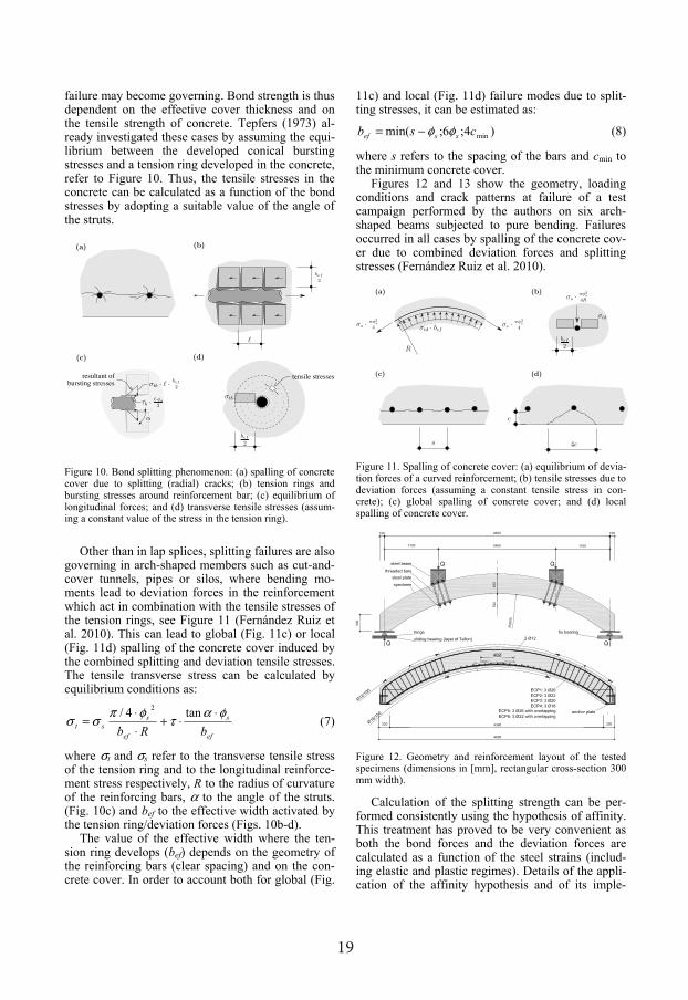
Figures 12 and 13 show the geometry, loading conditions and crack patterns at failure of a test campaign performed by the authors on six arch-shaped beams subjected to pure bending. Failures occurred in all cases by spalling of the concrete cov-er due to combined deviation forces and splitting stresses (Fernández Ruiz et al. 2010).
bef
2
s
c
4c
σs · πφ2s
4
R
(b)σs · πφ2
s
4R
σtd
σs · πφ2s
4
(a)
σtd · bef
(d)(c)
Figure 11. Spalling of concrete cover: (a) equilibrium of devia-tion forces of a curved reinforcement; (b) tensile stresses due to deviation forces (assuming a constant tensile stress in con-crete); (c) global spalling of concrete cover; and (d) local spalling of concrete cover.
Figure 12. Geometry and reinforcement layout of the tested specimens (dimensions in [mm], rectangular cross-section 300 mm width).
Calculation of the splitting strength can be per-formed consistently using the hypothesis of affinity. This treatment has proved to be very convenient as both the bond forces and the deviation forces are calculated as a function of the steel strains (includ-ing elastic and plastic regimes). Details of the appli-cation of the affinity hypothesis and of its imple-

20
mentation for these cases can be found elsewhere (Fernández Ruiz et al. 2010).
concrete coverspalling of
Figure 13. Cracking pattern at failure of tested specimens (Fernández Ruiz et al. 2010), all failures by spalling of con-crete cover.
For practical purposes of arch-shaped members, solving the general equation obtained through the hypothesis of affinity is however not necessary. In-stead, it can be reformulated using the following format (typically adopted in code provisions):
dtrefct qbfk ,≥⋅⋅ (9)
Where k is a strength reduction factor accounting for the strain effect of the longitudinal reinforcement on the tensile strength of concrete. For usual cases, adopting a value prior to bar yield-ing kel = ¼ leads to safe estimates of the spalling strength (Fernández Ruiz et al. 2010). For a more re-fined estimate of the strength reduction factor, its value can be calculated assuming that at bar yielding (qtr,d = fyd·π·φs
2/(4R)), no spalling of the concrete cover occurs. The following expression thus results (derived on the basis of the affinity assumptions, Fernández Ruiz et al. 2010):
bef
sel b
k κφ5.28.0 −= (10)
Where κb is a parameter whose value is equal to 2 in case of lap splices and to 1 otherwise. It can
be noted that factor κb accounts for the interaction between bond action and deviation forces in spalling
failures, which has shown to have a significant in-fluence on the strength and deformation capacity of RC members (Fernández Ruiz et al. 2010).
Calculation of the theoretical strength reduction factor for available test data is shown in Figure 14. The strain effect on the strength is notable and it de-creases the splitting strength for increasing values of the bar strain.
kpl
kel
εs [%]
k
3210
1
0.75
0.5
0.25
0
Figure 14. Comparison between measured and predicted failure loads for tests of figure 9 and others taken from the scientific literature (Fernández Ruiz et al. 2010) as a function of the lon-gitudinal strain of the bar (εs).
After bar yielding, and although the deviation forces remain approximately constant, the splitting stresses increase significantly due to the wedge ef-fect of the steel ribs. This implies that spalling fail-ures are also possible in the plastic regime, which has been confirmed experimentally for arch-shaped beams (Fernández Ruiz et al. 2010) and may govern the redistribution of internal forces necessary to de-velop a plastic mechanism for a vaulted construc-tion. In this regime, the value of the strength reduc-tion factor has to be reduced to kpl = 1/6 if safe estimates of the spalling strength are to be obtained, see Figure 14. Detailed analysis using the hypothesis of affinity is also possible in this regime (Fernández Ruiz et al. 2010).
4 SIZE EFFECTS IN SPLITTING FAILURES
Size effect in bond is a topic that has been widely investigated both for smooth and ribbed bars. A con-sistent approach and a discussion on the state-of-the –art to this problem can be consulted in fib 2000 and in Bamonte & Gambarova (2007).
With respect to ribbed bars, size effect is clearly present in splitting failures (insufficient concrete cover) since the strength is governed by the tensile strength of concrete (Bazant & Sener 1988). It how-ever also influences the strength of well-confined specimens as experimentally demonstrated by Ba-monte & Gambarova (2007). This can be explained by the local punching of concrete conical surfaces parallel to bursting struts (dependent on the bar di-

21
ameter, Fernández Ruiz et al 2007) and by the larger damage introduced in the concrete for larger bar ribs.
5 CONCLUSIONS
This paper presents an investigation on bond transfer actions and on the role of various geometrical and mechanical influences. Its main conclusions are: 1. Strain effects are relevant after yielding of the
reinforcement bars. This is due to the localiza-tion of strains in the plastic region which locally decreases bond stresses (for lateral contraction in tension) or increases (for lateral expansion in compression)
2. Bond in long specimens (where stresses vary along the reinforcement bar) can be consistently investigated by assuming perfect affinity be-tween the bond-reinforcement strain curves
3. Premature splitting failures can occur in arch-shaped members where tensile splitting stresses due to bond are potentially increased with the deviation forces of the curved reinforcement
4. Splitting strength of arch-shaped members is thus dependent of the strains in the reinforce-ment (strain effect) and can be investigated as-suming perfect affinity between the bond-reinforcement curves. Alternatively, simplified design methods based on strength reductions fac-tors of the tensile strength of concrete are possi-ble and practical for design in practical applica-tions
REFERENCES
Bamonte, P., and Gambarova, P. G. (2007). “High-Bond Bars in NSC and HPC: Study on Size Effect and on the Local Bond Stress-Slip Law.” Journal of Structural Engineering / Volume 133, No. 2, 225-234.
Bazant, Z. P., and Sener, S. (1988) “Size effect in pullout tests.” ACI Materials Journal, Vol. 85, No. 5, 347–351.
Fédération Internationale du Béton, fib (2000). “Bond of rein-forcement in concrete.” Bulletin No. 10, Sprint-Druck, Stuttgart, Germany.
Fédération Internationale du Béton, fib (2010a), “Model Code 2010 - First complete draft”, Bulletin 55, Lausanne, Swit-zerland, 2010, Vol. 1.
Fédération Internationale du Béton, fib (2010b), “Model Code 2010 - First complete draft”, Bulletin 56, Lausanne, Swit-zerland, 2010, Vol. 2.
Fédération Internationale du Béton, fib (2012, unpublished). “Bond and anchorage of reinforcement—Background to ptopose revisions in the fib Model Code 2010.” Fib TG 4.5 “Bond Models”.
Fernández Ruiz, M., Muttoni, A., and Gambarova, P. G., (2007a) “Analytical modeling of the pre- and post-yield be-havior of bond in reinforced concrete”, American Society of Civil Engineers, Journal of Structural Engineering, Vol. 133, No. 10, 1364—1372.
Fernández Ruiz, M., Muttoni, A., and Gambarova, P. G, (2007b) “A re-evaluation of test data on bond in R/C by
means of FE modeling”, Studies and Researches, Vol. 27, pub. by Starrylink, Brescia, Italy, Dec. 2007, 113—134.
Fernández Ruiz, M., Plumey, S., Muttoni, A., (2010) “Interac-tion between bond and deviation forces in spalling failures of arch-shaped members without transverse reinforcement”, American Concrete Institute, Structural Journal, Vol. 107, No. 3, 2010, 346—354.
Lee, S-C, Cho, J-Y, Vecchio, F.J., (2011), “Model for post-yield tension stiffening and rebar rupture in concrete mem-bers”, Engineering Structures, Vol. 33, 1723–1733.
Marti, P., Alvarez, M., Kaufmann, W., and Sigrist, V. (1998). “Tension chord model for structural concrete”, Struct. Eng. Int. (IABSE), Switzerland, Vol. 8, No. 4, 287-298.
Prieto Rábade, M., Tanner P., Fernández Ruiz, M., and An-drade Perdrix, M.C, (2012) “Experimental and numerical study of bond response in structural concrete with corroded steel bars”, Bond in Concrete: Bond, Anchorage, Detailing - 4th International Symposium, Brescia, Italy, 17-20 June, 2012.
Schenkel, M. (1998). “On bond behavior of reinforcing bars with limited cover.” Rep. No. 237, ETHZ, Swiss Federal Institute of Technology Zürich, Birkhäuser, Basel-Boston-Berlin, Switzerland.
Shima, H., Chou, L.-L., and Okamura, H. (1987). “Bond cha-racteristics in postyield range of deformed bars.” Concrete Library of JSCE, No. 10, Japan, 113–124.
Tepfers, R. (1973), “Theory of bond applied to overlapped reinforcement and spliced bars”, Chalmers Technical Uni-versity, Pub. 73:2, Gothenburg, Sweden.
