article 90 introduction - national fire protection association
TRANSCRIPT

ARTICLE 90 — INTRODUCTION 90.2
NOTE: The following draft shows how the draft of theproposed 2012 edition of NFPA 70E looks based on NFPAstaff’s reading of the Committee Actions contained in theNFPA 70E Technical Committee Report of the TechnicalCommittees on Electrical Safety in the Workplace (i.e., theCommittee Actions in the Report on Proposals). NFPA Stafffrequently prepare and make available drafts such as this asan aid to participants in reviewing Technical CommitteeReports. Participants are encouraged to review this Reporton Proposals and to raise any issues they believe need reso-lution through the making of appropriate comments. Pleasesubmit your public comments on the proposals, not on thedraft. As mentioned previously, the draft is only an aid forreviewing the document, incorporating the proposals.
For further information on NFPA codes and standardsdevelopment rules or on how to participate in the NFPAcodes and standards development process, check the NFPAwebsite at www.nfpa.org, or contact NFPA Codes and Stan-dards Administration at 617-770-3000, fax 617-770-3500,or email [email protected]
NFPA 70E
Electrical Safety in the Workplace®
2012 Edition
IMPORTANT NOTE: This NFPA document is madeavailable for use subject to important notices and legal dis-claimers. These notices and disclaimers appear in all publi-cations containing this document and may be found underthe heading “Important Notices and Disclaimers Concern-ing NFPA Documents.” They can also be obtained on re-quest from NFPA or viewed at www.nfpa.org/disclaimers.
This 2009 edition includes the following usability fea-tures as aids to the user. Changes other than editorial arehighlighted with gray shading within sections and with ver-tical ruling for large blocks of changed or new text and fornew tables and changed or new figures. Where one or morecomplete paragraphs have been deleted, the deletion is in-dicated by a bullet (•) between the paragraphs that remain.The index now has dictionary-style headers with helpfulidentifiers at the top of every index page.
A reference in brackets [ ] following a section or para-graph indicates material that has been extracted from an-other NFPA document. As an aid to the user, the completetitle and edition of the source documents for extracts aregiven in Annex A. Extracted text may be edited for consis-tency and style and may include the revision of internalparagraph references and other references as appropriate.Requests for interpretations or revisions of extracted textshall be sent to the technical committee responsible for thesource document.
Information on referenced publications can be found in
Annex A and Annex B.2012 Edition NATIONAL ELECTRICAL CODE
ARTICLE 90Introduction
90.1 Purpose. The purpose of this standard is to provide apractical safe working area for employees relative to thehazards arising from the use of electricity.
90.2 Scope.
(A) Covered. This standard addresses electrical safety re-quirements for employee workplaces that are necessary forthe practical safeguarding of employees during activitiessuch as the installation, inspection, operation, maintenance,and demolition of electric conductors, electric equipment,signaling and communications conductors and equipment,and raceways for the following: [ROP-9](1) Public and private premises, including buildings, struc-
tures, mobile homes, recreational vehicles, and floatingbuildings
(2) Yards, lots, parking lots, carnivals, and industrial sub-stations
(3) Installations of conductors and equipment that connectto the supply of electricity
(4) Installations used by the electric utility, such as officebuildings, warehouses, garages, machine shops, andrecreational buildings [ROP-11]
(B) Not Covered. This standard does not cover the follow-ing:
(1) Installations in ships, watercraft other than floatingbuildings, railway rolling stock, aircraft, or automotivevehicles other than mobile homes and recreational ve-hicles
(2) Installations underground in mines and self-propelledmobile surface mining machinery and its attendantelectrical trailing cable
(3) Installations of railways for generation, transformation,transmission, or distribution of power used exclusivelyfor operation of rolling stock or installations used ex-clusively for signaling and communications purposes
(4) Installations of communications equipment under theexclusive control of communications utilities locatedoutdoors or in building spaces used exclusively forsuch installations
70E–7

(
(
(
(
(
(
(
(
(
9t
(aos
(aqmb
(roiSa
dvTt
9idl
90.3 ARTICLE 90 — INTRODUCTION
(5) Installations under the exclusive control of an electricutility where such installations:
a. Consist of service drops or service laterals, and as-sociated metering, or
b. Are located in legally established easements orrights-of-way designated by or recognized by publicservice commissions, utility commissions, or otherregulatory agencies having jurisdiction for such in-stallations, or
c. Are on property owned or leased by the electricutility for the purpose of communications, metering,generation, control, transformation, transmission, ordistribution of electric energy.
90.3 Standard Arrangement. This standard is dividedinto the introduction and three chapters, as shown in Figure90.3. Chapter 1 applies generally for safety-related workpractices; Chapter 3 supplements or modifies Chapter 1with safety requirements for special equipment.
Chapter 2 applies to safety-related maintenance require-ments for electrical equipment and installations in work-places.
Annexes are not part of the requirements of this stan-dard but are included for informational purposes only.
90.4 Organization. This standard is divided into the fol-lowing three chapters and fifteen annexes:
(1) Chapter 1, Safety-Related Work Practices
(2) Chapter 2, Safety-Related Maintenance Requirements
(3) Chapter 3, Safety Requirements for Special Equip-ment
(4) Annex A, Referenced Publications
(5) Annex B, Informational References
(6) Annex C, Limits of Approach
(7) Annex D, Incident Energy and Flash ProtectionBoundary Calculation Methods
Chapter 3Safety Requirementsfor Special Equipment
Chapter 2Safety-Related
Maintenance Requirements
Chapter 1Safety-RelatedWork Practices
Applies generally to electrical safety in the workplace
Safety requirements for special equipment; supplements and/or modifies Chapter 1
Safety related maintenance requirements
Figure 90.3 Standard Arrangement.
(8) Annex E, Electrical Safety Program C
70E–8
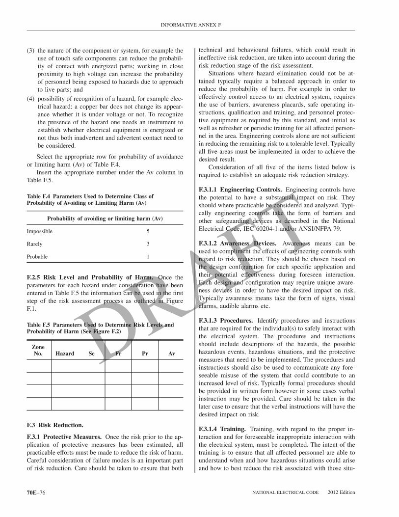
(9) Annex F, Hazard/Risk Evaluation Procedure
10) Annex G, Sample Lockout/Tagout Procedure
11) Annex H, Simplified, Two-Category, Arc-RatedClothing System
12) Annex I, Job Briefing and Planning Checklist
13) Annex J, Energized Electrical Work Permit
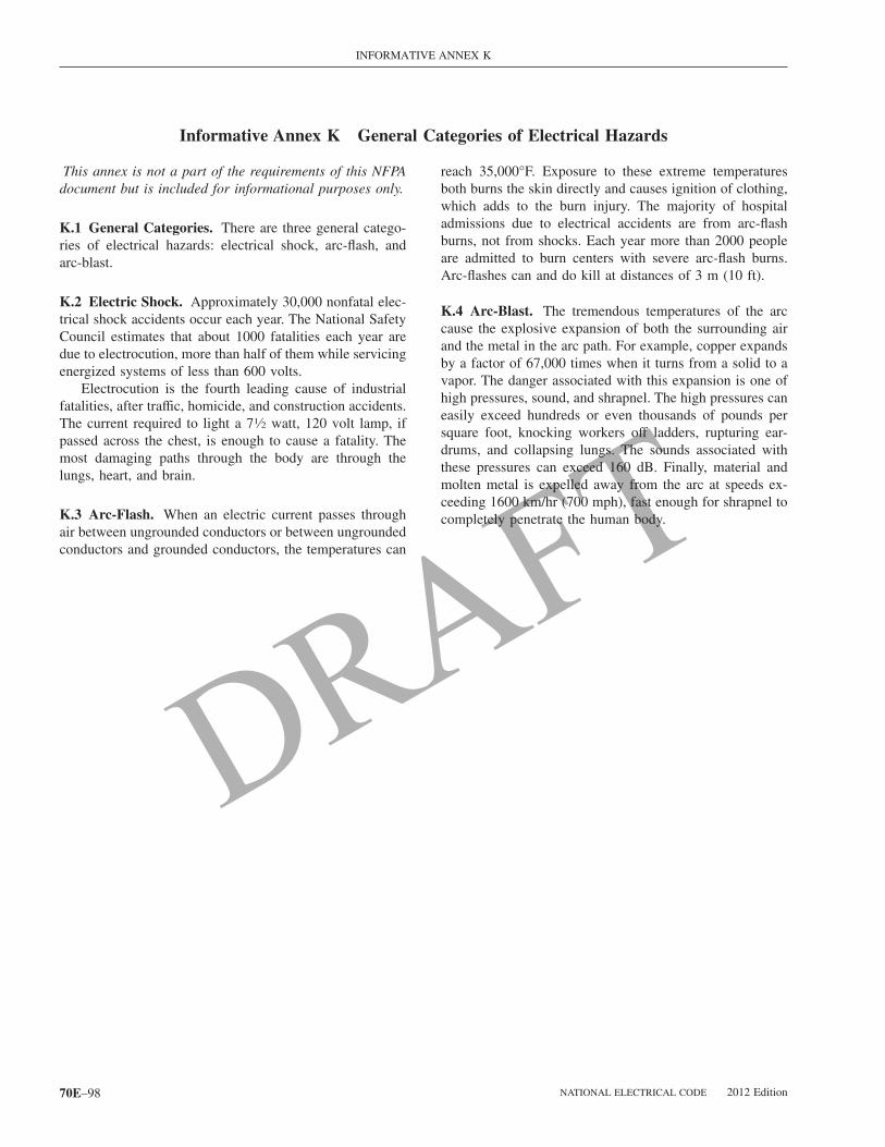
14) Annex K, General Categories of Electrical Hazards
15) Annex L, Typical Application of Safeguards in theCell Line Working Zone
16) Annex M, Layering of Protective Clothing and TotalSystem Arc Rating
17) Annex N, Example Industrial Procedures and Policiesfor Working Near Overhead Electrical Lines andEquipment
18) Annex O, Safety-Related Design Requirements
0.5 Mandatory Rules, Permissive Rules, and Explana-ory Material.
A) Mandatory Rules. Mandatory rules of this standardre those that identify actions that are specifically requiredr prohibited and are characterized by the use of the termshall or shall not.
B) Permissive Rules. Permissive rules of this standardre those that identify actions that are allowed but not re-uired, are normally used to describe options or alternativeethods, and are characterized by the use of the terms shall
e permitted or shall not be required.
C) Explanatory Material. Explanatory material, such aseferences to other standards, references to related sectionsf this standard, or information related to a Code rule, isncluded in this standard in the form of informational notes.uch notes are informational only and are not enforceables requirements of this standard. [ROP-13]
Brackets containing section references to another NFPAocument are for informational purposes only and are pro-ided as a guide to indicate the source of the extracted text.hese bracketed references immediately follow the ex-
racted text.
Informational Note: The format and language used in thisstandard follow guidelines established by NFPA and pub-lished in the NEC Style Manual. Copies of this manual canbe obtained from NFPA.
0.6 Formal Interpretations. To promote uniformity ofnterpretation and application of the provisions of this stan-ard, formal interpretation procedures have been estab-ished and are found in the NFPA Regulations Governing
ommittee Projects.NATIONAL ELECTRICAL CODE 2012 Edition

ARTICLE 100 — DEFINITIONS CHAPTER 1
•
•
Chapter 1 Safety-Related Work Practices
ARTICLE 100Definitions
Scope. This article contains only those definitions es-sential to the proper application of this standard. It is notintended to include commonly defined general terms orcommonly defined technical terms from related codes andstandards. In general, only those terms that are used in twoor more articles are defined in Article 100. Other definitionsare included in the article in which they are used but maybe referenced in Article 100. The definitions in this articleshall apply wherever the terms are used throughout thisstandard.
I. General
Accessible (as applied to equipment). Admitting closeapproach; not guarded by locked doors, elevation, or othereffective means. [70, 2008]
Accessible (as applied to wiring methods). Capable ofbeing removed or exposed without damaging the buildingstructure or finish or not permanently closed in by the struc-ture or finish of the building. [70, 2008]
Accessible, Readily (Readily Accessible). Capable of be-ing reached quickly for operation, renewal, or inspectionswithout requiring those to whom ready access is requisiteto climb over or remove obstacles or to resort to portableladders, and so forth. [70, 2008]
Ampacity. The current, in amperes, that a conductor cancarry continuously under the conditions of use without ex-ceeding its temperature rating. [70, 2008][ROP-13a]
Approved. Acceptable to the authority having jurisdiction.
Arc Flash Hazard. A dangerous condition associated withthe possible release of energy caused by an electric arc.
Informational Note No. 1: An arc flash hazard may existwhen energized electrical conductors or circuit parts areexposed or when they are within equipment in a guarded orenclosed condition, provided a person is interacting withthe equipment in such a manner that could cause an electricarc. Under normal operating conditions, enclosed energizedequipment that has been properly installed and maintainedis not likely to pose an arc flash hazard.
Informational Note No. 2: See Table 130.8(C)(15)(1) forexamples of activities that could pose an arc flash hazard.[ROP-18]
Arc Flash Hazard Analysis. A study investigating a work-
er’s potential exposure to arc-flash energy, conducted for2012 Edition NATIONAL ELECTRICAL CODE
the purpose of injury prevention and the determination ofsafe work practices, arc flash protection boundary, and theappropriate levels of PPE.
Arc Flash Suit. A complete arc-rated clothing and equip-ment system that covers the entire body, except for thehands and feet. [ROP-22]
Informational Note: An arc-flash suit may include pants oroveralls, jacket, or a coverall and beekeeper-type hood fit-ted with a face shield. [ROP-22]
Arc Rating. The value attributed to materials that describestheir performance to exposure to an electrical arc discharge.The arc rating is expressed in cal/cm2 and is derived fromthe determined value of the arc thermal performance value(ATPV) or energy of breakopen threshold (EBT) (should amaterial system exhibit a breakopen response below theATPV value). Arc rating is reported as either ATPV or EBT,whichever is the lower value. [ROP-24]
Informational Note No. 1: Breakopen is a material re-sponse evidenced by the formation of one or more holes inthe innermost layer of arc-rated material that would allowflame to pass through the material.
Informational Note No. 2: ATPV is defined in ASTM F1959-06 as the incident energy on a material or a multi-layer system of materials that results in a 50% probabilitythat sufficient heat transfer through the tested specimen ispredicted to cause the onset of a second-degree skin burninjury based on the Stoll curve, cal/cm2. [ROP-24]
Informational Note No. 3: EBT is defined in ASTM F1959-06 as the incident energy on a material or materialsystem that results in a 50% probability of breakopen.Breakopen is defined as a hole with an area of 1.6 cm2
(0.5 in2) or an opening with a 2.5 cm (1.0 in.) in anydimension. [ROP-24]
Attachment Plug (Plug Cap) (Plug). A device that, byinsertion in a receptacle, establishes a connection betweenthe conductors of the attached flexible cord and the conduc-tors connected permanently to the receptacle. [70, 2008]
Authority Having Jurisdiction (AHJ). An organization,office, or individual responsible for enforcing the require-ments of a code or standard, or approving equipment, ma-terials, an installation, or a procedure.
Informational Note: The phrase “authority having jurisdic-tion,” or its acronym AHJ, is used in NFPA documents in abroad manner, since jurisdictions and approval agenciesvary, as do their responsibilities. Where public safety isprimary, the authority having jurisdiction may be a federal,state, local, or other regional department or individual suchas a fire chief; fire marshal; chief of a fire prevention bu-reau, labor department, or health department; building offi-
cial; electrical inspector; or others having statutory author-70E–9

Bo[[
Bs
Cmmb
Cctt
C[
Cgd2[
Cvrmsd
Chols
Ctt
Dsn
Dt
Dod
DI
CHAPTER 1 ARTICLE 100 — DEFINITIONS
•
•
•
ity. For insurance purposes, an insurance inspectiondepartment, rating bureau, or other insurance company rep-resentative may be the authority having jurisdiction. Inmany circumstances, the property owner or his or her des-ignated agent assumes the role of the authority having ju-risdiction; at government installations, the commanding of-ficer or departmental official may be the authority havingjurisdiction.
Automatic. Performing a function without the necessity ofhuman intervention. [ROP-25]
Balaclava (Sock Hood). An arc-rated hood that protectsthe neck and head except for facial area of the eyes andnose. [ROP-27]
Bare-Hand Work. A technique of performing work on en-ergized electrical conductors or circuit parts, after the em-ployee has been raised to the potential of the conductor orcircuit part.
Barricade. A physical obstruction such as tapes, cones, orA-frame-type wood or metal structures intended to providea warning about and to limit access to a hazardous area.
Barrier. A physical obstruction that is intended to preventcontact with equipment or energized electrical conductorsand circuit parts or to prevent unauthorized access to awork area.
Bonded (Bonding). Connected to establish electrical con-tinuity and conductivity. [70, 2008]
Bonding Jumper. A reliable conductor to ensure the re-quired electrical conductivity between metal parts requiredto be electrically connected. [70, 2008]
Boundary, Arc Flash. [ROP-30] When an arc flash hazardexists, an approach limit at a distance from a prospectivearc source within which a person could receive a seconddegree burn if an electrical arc flash were to occur.
Informational Note: A second degree burn is possible byan exposure of unprotected skin to an electric arc flashabove the incident-energy level of 5 J/cm2 (1.2 cal/cm2).[ROP-29]
Boundary, Limited Approach. An approach limit at a dis-tance from an exposed energized electrical conductor orcircuit part within which a shock hazard exists.
Boundary, Prohibited Approach. An approach limit at adistance from an exposed energized electrical conductor orcircuit part within which work is considered the same asmaking contact with the electrical conductor or circuit part.
Boundary, Restricted Approach. An approach limit at adistance from an exposed energized electrical conductor orcircuit part within which there is an increased risk of shock,due to electrical arc over combined with inadvertent move-ment, for personnel working in close proximity to the en-
ergized electrical conductor or circuit part. a70E–10
ranch Circuit. The circuit conductors between the finalvercurrent device protecting the circuit and the outlet(s).70, 2008]ROP-36]
uilding. Any structure used or intended for supporting orheltering any use or occupancy. [101, 2009] [ROP-37]
abinet. An enclosure that is designed for either surfaceounting or flush mounting and is provided with a frame,at, or trim in which a swinging door or doors are or can
e hung. [70, 2008]
ircuit Breaker. A device designed to open and close aircuit by nonautomatic means and to open the circuit au-omatically on a predetermined overcurrent without damageo itself when properly applied within its rating. [70, 2008]
Informational Note: The automatic opening means can beintegral, direct acting with the circuit breaker, or remotefrom the circuit breaker. [70, 2008]
onductive. Suitable for carrying electric current.ROP-38, ROP-39, ROP-40]
ontroller. A device or group of devices that serves toovern, in some predetermined manner, the electric powerelivered to the apparatus to which it is connected. [70,008]ROP-41]
urrent-Limiting Overcurrent Protective Device. A de-ice that, when interrupting currents in its current-limitingange, reduces the current flowing in the faulted circuit to aagnitude substantially less than that obtainable in the
ame circuit if the device were replaced with a solid con-uctor having comparable impedance.
utout. An assembly of a fuse support with either a fuse-older, fuse carrier, or disconnecting blade. The fuseholderr fuse carrier may include a conducting element (fuseink), or may act as the disconnecting blade by the inclu-ion of a nonfusible member.
utout Box. An enclosure designed for surface mountinghat has swinging doors or covers secured directly to andelescoping with the walls of the box proper. [70, 2008]
eenergized. Free from any electrical connection to aource of potential difference and from electrical charge;ot having a potential different from that of the earth.
evice. A unit of an electrical system that carries or con-rols electric energy as its principal function. [70, 2008]
isconnecting Means. A device, or group of devices, orther means by which the conductors of a circuit can beisconnected from their source of supply. [70, 2008]
isconnecting (or Isolating) Switch (Disconnector,solator). A mechanical switching device used for isolating
circuit or equipment from a source of power.NATIONAL ELECTRICAL CODE 2012 Edition

ARTICLE 100 — DEFINITIONS CHAPTER 1
•
•
•
•
Electrical Hazard. A dangerous condition such that con-tact or equipment failure can result in electric shock, arcflash burn, thermal burn, or blast.
Informational Note: Class 2 power supplies, listed lowvoltage lighting systems, and similar sources are examplesof circuits or systems that are not considered an electricalhazard.
Electrical Safety. Recognizing hazards associated with theuse of electrical energy and taking precautions so that haz-ards do not cause injury or death.
Electrically Safe Work Condition. A state in which anelectrical conductor or circuit part has been disconnectedfrom energized parts, locked/tagged in accordance with es-tablished standards, tested to ensure the absence of voltage,and grounded if determined necessary.
Enclosed. Surrounded by a case, housing, fence, or wall(s)that prevents persons from accidentally contacting ener-gized parts. [70, 2008] [ROP-49]
Enclosure. The case or housing of apparatus, or the fenceor walls surrounding an installation to prevent personnelfrom accidentally contacting energized parts or to protectthe equipment from physical damage. [70, 2008] [ROP-49]
Energized. Electrically connected to, or is, a source ofvoltage. [70, 2008]
Equipment. A general term, including material, fittings,devices, appliances, luminaires, apparatus, machinery, andthe like used as a part of, or in connection with, an electri-cal installation. [70, 2008][ROP-50]
Exposed (as applied to energized electrical conductorsor circuit parts). Capable of being inadvertently touchedor approached nearer than a safe distance by a person. It isapplied to electrical conductors or circuit parts that are notsuitably guarded, isolated, or insulated.
Exposed (as applied to wiring methods). On or attachedto the surface or behind panels designed to allow access.[70, 2008][ROP-53, ROP-54]
Fitting. An accessory such as a locknut, bushing, or otherpart of a wiring system that is intended primarily to per-form a mechanical rather than an electrical function. [70,2008][ROP-55]
Fuse. An overcurrent protective device with a circuit-opening fusible part that is heated and severed by the pas-sage of overcurrent through it.
Informational Note: A fuse comprises all the parts that
form a unit capable of performing the prescribed functions.2012 Edition NATIONAL ELECTRICAL CODE
It may or may not be the complete device necessary toconnect it into an electrical circuit.
Ground. The earth. [70, 2008]
Grounded (Grounding). Connected (connecting) toground or to a conductive body that extends the groundconnection. [70, 2008]
Grounded, Solidly. Connected to ground without insertingany resistor or impedance device. [70, 2008]
Grounded Conductor. A system or circuit conductor thatis intentionally grounded. [70, 2008]
Ground Fault. An unintentional, electrically conductingconnection between an ungrounded conductor of an electri-cal circuit and the normally non–current-carrying conduc-tors, metallic enclosures, metallic raceways, metallic equip-ment, or earth.
Ground-Fault Circuit-Interrupter (GFCI). A device in-tended for the protection of personnel that functions to de-energize a circuit or portion thereof within an establishedperiod of time when a current to ground exceeds the valuesestablished for a Class A device. [70, 2008]
Informational Note: Class A ground-fault circuit-interrupters trip when the current to ground is 6 mA orhigher and do not trip when the current to ground is lessthan 4 mA. For further information, see ANSI/UL 943,Standard for Ground-Fault Circuit Interrupters. [ROP-59,ROP-60]
Grounding Conductor, Equipment (EGC). The conduc-tive path installed to connect normally non–current-carrying metal parts of equipment together and to the sys-tem grounded conductor or to the grounding electrodeconductor, or both. [70, 2008]
Informational Note No. 1: It is recognized that the equip-ment grounding conductor also performs bonding.
Informational Note No. 2: See NFPA 70, Section 250.118for a list of acceptable equipment grounding conductors.
Grounding Electrode. A conducting object through whicha direct connection to earth is established. [70, 2008]
Grounding Electrode Conductor. A conductor used toconnect the system grounded conductor or the equipment toa grounding electrode or to a point on the grounding elec-trode system. [70, 2008]
Guarded. Covered, shielded, fenced, enclosed, or other-wise protected by means of suitable covers, casings, barri-ers, rails, screens, mats, or platforms to remove the likeli-hood of approach or contact by persons or objects to a pointof danger. [70, 2008]
Incident Energy. The amount of energy impressed on asurface, a certain distance from the source, generated dur-
ing an electrical arc event. One of the units used to measure70E–11

laIbl
Mcp
Ntn[
Ot
Oef
Ofiws[
Psbwpba
PitwTsp
at
Qlet
R
CHAPTER 1 ARTICLE 100 — DEFINITIONS
•
•
incident energy is calories per centimeter squared(cal/cm2).
Incident Energy Analysis. A study used to predict theincident energy of an arc flash for a specified set of condi-tions. [ROP-19]
Insulated. Separated from other conducting surfaces by adielectric (including air space) offering a high resistance tothe passage of current.
Informational Note: When an object is said to be insu-lated, it is understood to be insulated for the conditions towhich it is normally subject. Otherwise, it is, within thepurpose of these rules, uninsulated.
Interrupter Switch. A switch capable of making, carrying,and interrupting specified currents.
Interrupting Rating. The highest current at rated voltagethat a device is intended to interrupt under standard testconditions. [70, 2008]
Informational Note: Equipment intended to interrupt cur-rent at other than fault levels may have its interruptingrating implied in other ratings, such as horsepower orlocked rotor current.
Isolated (as applied to location). Not readily accessible topersons unless special means for access are used. [70,2008]
Labeled. Equipment or materials to which has been at-tached a label, symbol, or other identifying mark of anorganization that is acceptable to the authority having juris-diction and concerned with product evaluation, that main-tains periodic inspection of production of labeled equip-ment or materials, and by whose labeling the manufacturerindicates compliance with appropriate standards or perfor-mance in a specified manner.
Listed. Equipment, materials, or services included in a listpublished by an organization that is acceptable to the au-thority having jurisdiction and concerned with evaluationof products or services, that maintains periodic inspectionof production of listed equipment or materials or periodicevaluation of services, and whose listing states that eitherthe equipment, material, or services meets appropriate des-ignated standards or has been tested and found suitable fora specified purpose.
Informational Note: The means for identifying listedequipment may vary for each organization concerned withproduct evaluation, some of which do not recognize equip-ment as listed unless it is also labeled. Use of the systememployed by the listing organization allows the authorityhaving jurisdiction to identify a listed product.[ROP-61]
Luminaire. A complete lighting unit consisting of a lamp
or lamps, together with the parts designed to distribute the m70E–12
ight, to position and protect the lamps and ballast (wherepplicable), and to connect the lamps to the power supply.t may also include parts to protect the light source or theallast or to distribute the light. A lampholder is not auminaire. [70, 2008]
otor Control Center. An assembly of one or more en-losed sections having a common power bus and princi-ally containing motor control units. [70, 2008]
eutral Conductor. The conductor connected to the neu-ral point of a system that is intended to carry current underormal conditions. [70, 2008]ROP-62, ROP-63]
utlet. A point on the wiring system at which current isaken to supply utilization equipment. [70, 2008]
vercurrent. Any current in excess of the rated current ofquipment or the ampacity of a conductor. It may resultrom overload, short circuit, or ground fault. [70, 2008]
Informational Note: A current in excess of rating may beaccommodated by certain equipment and conductors for agiven set of conditions. Therefore, the rules for overcurrentprotection are specific for particular situations.
verload. Operation of equipment in excess of normal,ull-load rating, or of a conductor in excess of rated ampac-ty that, when it persists for a sufficient length of time,ould cause damage or dangerous overheating. A fault,
uch as a short circuit or ground fault, is not an overload.70, 2008]
anelboard. A single panel or group of panel units de-igned for assembly in the form of a single panel, includinguses and automatic overcurrent devices, and equippedith or without switches for the control of light, heat, orower circuits; designed to be placed in a cabinet or cutoutox placed in or against a wall, partition, or other support;nd accessible only from the front. [70, 2008]
remises Wiring (System). Interior and exterior wiring,ncluding power, lighting, control, and signal circuit wiringogether with all their associated hardware, fittings, andiring devices, both permanently and temporarily installed.his includes: (a) wiring from the service point or powerource to the outlets; or (b) wiring from and including theower source to the outlets where there is no service point.
Such wiring does not include wiring internal to appli-nces, luminaires, motors, controllers, motor control cen-ers, and similar equipment. [70, 2008]
ualified Person. One who has skills and knowledge re-ated to the construction and operation of the electricalquipment and installations and has received safety trainingo recognize and avoid the hazards involved. [70, 2008]
aceway. An enclosed channel of metal or nonmetallic
aterials designed expressly for holding wires, cables, orNATIONAL ELECTRICAL CODE 2012 Edition
ARTICLE 100 — DEFINITIONS CHAPTER 1
•
•
busbars, with additional functions as permitted in this stan-dard. Raceways include, but are not limited to, rigid metalconduit, rigid nonmetallic conduit, intermediate metal con-duit, liquidtight flexible conduit, flexible metallic tubing,flexible metal conduit, electrical metallic tubing, electricalnonmetallic tubing, underfloor raceways, cellular concretefloor raceways, cellular metal floor raceways, surface race-ways, wireways, and busways. [70, 2008]
Receptacle. A receptacle is a contact device installed at theoutlet for the connection of an attachment plug. A singlereceptacle is a single contact device with no other contactdevice on the same yoke. A multiple receptacle is two ormore contact devices on the same yoke. [70, 2008][ROP-65, ROP-66]
Service Conductors. The conductors from the servicepoint to the service disconnecting means. [70, 2008]
Service Drop. The overhead service conductors from thelast pole or other aerial support to and including the splices,if any, connecting to the service-entrance conductors at thebuilding or other structure. [70, 2008] [ROP-68, ROP-69,ROP-67]
Service Lateral. The underground service conductors be-tween the street main, including any risers at a pole or otherstructure or from transformers, and the first point of con-nection to the service-entrance conductors in a terminal boxor meter or other enclosure, inside or outside the buildingwall. Where there is no terminal box, meter, or other enclo-sure, the point of connection is considered to be the point ofentrance of the service conductors into the building. [70,2008]
Service Point. The point of connection between the facili-ties of the serving utility and the premises wiring. [70,2008]
Shock Hazard. A dangerous condition associated with thepossible release of energy caused by contact or approach toenergized electrical conductors or circuit parts.
Short-Circuit Current Rating. The prospective symmetri-cal fault current at a nominal voltage to which an apparatusor system is able to be connected without sustaining dam-age exceeding defined acceptance criteria. [70, 2008]
Single-Line Diagram. A diagram that shows, by means ofsingle lines and graphic symbols, the course of an electriccircuit or system of circuits and the component devices orparts used in the circuit or system.
Special Permission. The written consent of the authorityhaving jurisdiction. [70, 2008]
Step Potential. A ground potential gradient difference that
can cause current flow from foot to foot through the body.2012 Edition NATIONAL ELECTRICAL CODE
Structure. That which is built or constructed. [70, 2008]
Switch, Isolating. A switch intended for isolating an elec-tric circuit from the source of power. It has no interruptingrating, and it is intended to be operated only after the circuithas been opened by some other means. [70, 2008]
Switchboard. A large single panel, frame, or assembly ofpanels on which are mounted on the face, back, or both,switches, overcurrent and other protective devices, buses,and usually instruments. Switchboards are generally acces-sible from the rear as well as from the front and are notintended to be installed in cabinets. [70, 2008]
Switchgear, Arc-Resistant. Equipment designed to with-stand the effects of an internal arcing fault and that directsthe internally released energy away from the employee.
Switchgear, Metal-Clad. A switchgear assembly com-pletely enclosed on all sides and top with sheet metal, hav-ing drawout switching and interrupting devices, and all liveparts enclosed within grounded metal compartments.
Switchgear, Metal-Enclosed. A switchgear assembly com-pletely enclosed on all sides and top with sheet metal (ex-cept for ventilating openings and inspection windows), con-taining primary power circuit switching, interruptingdevices, or both, with buses and connections. This assem-bly may include control and auxiliary devices. Access tothe interior of the enclosure is provided by doors, remov-able covers, or both. Metal-enclosed switchgear is availablein non-arc-resistant or arc-resistant constructions.
Switching Device. A device designed to close, open, orboth, one or more electric circuits.
Touch Potential. A ground potential gradient differencethat can cause current flow from hand to hand, hand to foot,or another path, other than foot to foot, through the body.
Ungrounded. Not connected to ground or to a conductivebody that extends the ground connection. [70, 2008]
Unqualified Person. A person who is not a qualified per-son.
Utilization Equipment. Equipment that utilizes electricenergy for electronic, electromechanical, chemical, heating,lighting, or similar purposes. [70, 2008]
Ventilated. Provided with a means to permit circulation ofair sufficient to remove an excess of heat, fumes, or vapors.[70, 2008]
Voltage (of a Circuit). The greatest root-mean-square(rms) (effective) difference of potential between any twoconductors of the circuit concerned. [70, 2008]
Informational Note: Some systems, such as 3-phase4-wire, single-phase 3-wire, and 3-wire direct-current, may
have various circuits of various voltages.70E–13

At
1P
((
(
((
(
(
(b[
1
(
105.1 ARTICLE 110 — GENERAL REQUIREMENTS FOR ELECTRICAL SAFETY-RELATED WORK PRACTICES
•
Voltage, Nominal. A nominal value assigned to a circuit orsystem for the purpose of conveniently designating its volt-age class (e.g., 120/240 volts, 480Y/277 volts, 600 volts).The actual voltage at which a circuit operates can vary fromthe nominal within a range that permits satisfactory opera-tion of equipment. [70, 2008]
Informational Note: See ANSI C84.1-2006, ElectricPower Systems and Equipment — Voltage Ratings (60 Hz).[ROP-72]
Working On (energized electrical conductors or circuitparts). Intentionally coming in contact with energized elec-trical conductors or circuit parts with the hands, feet, orother body parts, with tools, probes, or with test equipment,regardless of the personal protective equipment a person iswearing. There are two categories of “working on”: Diag-nostic (testing) is taking readings or measurements of elec-trical equipment with approved test equipment that does notrequire making any physical change to the equipment; re-pair is any physical alteration of electrical equipment (suchas making or tightening connections, removing or replacingcomponents, etc.). [ROP-73]
ARTICLE 105Application of Safety-Related Work
Practices [ROP-76]
105.1 Scope. Chapter 1 covers electrical safety-relatedwork practices and procedures for employees who are ex-posed to an electrical hazard in workplaces covered in thescope of this standard. Electric circuits and equipment notincluded in the scope of this standard might present a haz-ard to employees working near such facilities. [ROP-76,ROP-77].
105.2 Purpose. These practices and procedures are in-tended to provide for employee safety relative to specificidentified electrical hazards in the workplace. [ROP-76]
Informational Note: For general categories of electricalhazards, see Annex K.
105.3 Responsibility [ROP-80]. The employer shall pro-vide the safety-related work practices and shall train theemployee who shall then implement them. [ROP-76]
105.4 Organization. Chapter 1 of this standard is dividedinto four articles. Article 100 provides definitions for termsused in one or more of the chapters of this document. Ar-ticle 110 provides general requirements for electricalsafety-related work practices. Article 120 provides require-
ments for establishing an electrically safe work condition. i70E–14
rticle 130 provides requirements for work involving elec-rical hazards. [ROP-76]
ARTICLE 110General Requirements for Electrical
Safety-Related Work Practices
10.1 Relationships with Contractors (Outside Serviceersonnel, etc.).
A) Host Employer Responsibilities.1) The host employer shall inform contract employers of:
a. Known hazards that are covered by this standard,that are related to the contract employer’s work, andthat might not be recognized by the contract em-ployer or its employees
b. Information about the employer’s installation thatthe contract employer needs to make the assess-ments required by Chapter 1
2) The host employer shall report observed contract-employer-related violations of this standard to the con-tract employer.
B) Contract Employer Responsibilities.1) The contract employer shall ensure that each of his or
her employees is instructed in the hazards communi-cated to the contract employer by the host employer.This instruction is in addition to the basic training re-quired by this standard.
2) The contract employer shall ensure that each of his orher employees follows the work practices required bythis standard and safety-related work rules required bythe host employer.
3) The contract employer shall advise the host employerof:
a. Any unique hazards presented by the contract em-ployer’s work,
b. Any unanticipated hazards found during the con-tract employer’s work that the host employer did notmention, and
c. The measures the contractor took to correct any vio-lations reported by the host employer under para-graph (A)(2) of this section and to prevent suchviolation from recurring in the future.
C) Documentation. There shall be a documented meetingetween the host employer and the contract employer.ROP-89]
10.2 Training Requirements.
A) Safety Training. The training requirements contained
n this section shall apply to employees who face a risk ofNATIONAL ELECTRICAL CODE 2012 Edition

ARTICLE 110 — GENERAL REQUIREMENTS FOR ELECTRICAL SAFETY-RELATED WORK PRACTICES 110.2
electrical hazard that is not reduced to a safe level by theapplicable electrical installation requirements. Such em-ployees shall be trained to understand the specific hazardsassociated with electrical energy. They shall be trained insafety-related work practices and procedural requirementsas necessary to provide protection from the electrical haz-ards associated with their respective job or task assign-ments. Employees shall be trained to identify and under-stand the relationship between electrical hazards andpossible injury.
Informational Note: For further information concerninginstallation requirements, see NFPA 70®, National Electri-cal Code®, 2008 edition.
(B) Type of Training. The training required by this sectionshall be classroom or on-the-job type, or a combination ofthe two. The degree of training provided shall be deter-mined by the risk to the employee.
(C) Emergency Procedures. Employees responsible fortaking action in case of emergency shall be trained in meth-ods of release of victims from contact with exposed ener-gized electrical conductors or circuit parts. Employees shallbe regularly instructed in methods of first aid and emer-gency procedures, such as approved methods of resuscita-tion, if their duties warrant such training. Training of em-ployees in approved methods of resuscitation, includingcardiopulmonary resuscitation and automatic externaldefibrillator (AED) use, shall be certified by the employerannually. [ROP-93] [ROP-92]
(D) Employee Training.
(1) Qualified Person. A qualified person shall be trainedand knowledgeable of the construction and operation ofequipment or a specific work method and be trained torecognize and avoid the electrical hazards that might bepresent with respect to that equipment or work method.
(a) Such persons shall also be familiar with the properuse of the special precautionary techniques, personal pro-tective equipment, including arc-flash, insulating andshielding materials, and insulated tools and test equipment.A person can be considered qualified with respect to certainequipment and methods but still be unqualified for others.
(b) Such persons permitted to work within the LimitedApproach Boundary of exposed energized electrical con-ductors and circuit parts operating at 50 volts or more shall,at a minimum, be additionally trained in all of the follow-ing:(1) The skills and techniques necessary to distinguish ex-
posed energized electrical conductors and circuit partsfrom other parts of electrical equipment
(2) The skills and techniques necessary to determine thenominal voltage of exposed energized electrical con-
ductors and circuit parts2012 Edition NATIONAL ELECTRICAL CODE
(3) The approach distances specified in Table 130.4(C)(1)and the corresponding voltages to which the qualifiedperson will be exposed
(4) The decision-making process necessary to determinethe degree and extent of the hazard and the personalprotective equipment and job planning necessary toperform the task safely
(c) An employee who is undergoing on-the-job train-ing for the purpose of obtaining the skills and knowledgenecessary to be considered a qualified person and who, inthe course of such training, has demonstrated an ability toperform specific duties safely at his or her level of trainingand who is under the direct supervision of a qualified per-son shall be considered to be a qualified person for theperformance of those specific duties. [ROP-97] [ROP-98]
(d) Tasks that are performed less often than once peryear shall require retraining before the performance of thework practices involved.
(e) Employees shall be trained to select an appropriatevoltage detector and shall demonstrate how to use a deviceto verify the absence of voltage, including interpreting in-dications provided by the device. The training shall includeinformation that enables the employee to understand alllimitations of each specific voltage detector that may beused.
(f) The employer shall determine, through regular su-pervision and through inspections conducted on at least anannual basis that each employee is complying with thesafety-related work practices required by this standard.[ROP-100]
(2) Unqualified Persons. Unqualified persons shall betrained in and be familiar with any electrical safety-relatedpractices necessary for their safety. [ROP-101]
(3) Retraining. An employee shall receive additionaltraining (or retraining) under any of the following condi-tions:
(a) If the supervision or annual inspections indicatethat the employee is not complying with the safety-relatedwork practices
(b) If new technology, new types of equipment, orchanges in procedures necessitate the use of safety-relatedwork practices that are different from those that the em-ployee would normally use
(c) If he or she must employ safety-related work prac-tices that are not normally used during his or her regularjob duties
(d) Retraining shall be performed at intervals not toexceed 3 years. [ROP-104]
(E) Training Documentation. The employer shall docu-ment that each employee has received the training required
by paragraph 110.2 (D). This documentation shall be made70E–15

cAacehe
(
(cvapeho
(tab1
(sida
(
(
(
(gppf1
(t
110.3 ARTICLE 110 — GENERAL REQUIREMENTS FOR ELECTRICAL SAFETY-RELATED WORK PRACTICES
when the employee demonstrates proficiency in the workpractices involved and shall be maintained for the durationof the employee’s employment. The documentation shallcontain the content of the training, each employee’s name,and dates of training. [ROP-105]
Informational Note: Employment records that indicate thatan employee has received the required training are an ac-ceptable means of meeting this requirement.
110.3 Electrical Safety Program.
(A) General. The employer shall implement and documentan overall electrical safety program that directs activity ap-propriate for the electrical hazards, voltage, energy level,and circuit conditions. [ROP-107]
Informational Note No. 1: Safety-related work practicesare just one component of an overall electrical safetyprogram.
Informational Note No. 2: ANSI/AIHA Z10-2005, Ameri-can National Standard for Occupational Safety and HealthManagement Systems, provides a framework for establish-ing a comprehensive electrical safety program as a compo-nent of an employer’s occupational safety and healthprogram.
(B) Awareness and Self-Discipline. The electrical safetyprogram shall be designed to provide an awareness of thepotential electrical hazards to employees who work in anenvironment with the presence of electrical hazards. Theprogram shall be developed to provide the required self-discipline for all employees who must perform work thatmay involve electrical hazards. The program shall instillsafety principles and controls. [ROP-108]
(C) Electrical Safety Program Principles. The electricalsafety program shall identify the principles upon which it isbased.
Informational Note: For examples of typical electricalsafety program principles, see Annex E.
(D) Electrical Safety Program Controls. An electricalsafety program shall identify the controls by which it ismeasured and monitored.
Informational Note: For examples of typical electricalsafety program controls, see Annex E.
(E) Electrical Safety Program Procedures. An electricalsafety program shall identify the procedures for workingwithin the Limited Approach Boundary and for workingwithin the arc flash boundary before work is started. [ROP-111]
Informational Note: For an example of a typical electricalsafety program procedure, see Annex E.
(F) Hazard/Risk Evaluation Procedure. An electrical
safety program shall identify a hazard/risk evaluation pro- d70E–16
edure to be used before work is started within the Limitedpproach Boundary and before work is started within the
rc flash boundary of energized electrical conductors andircuit parts operating at 50 volts or more or where anlectrical hazard exists. The procedure shall identify theazard/risk process that shall be used by employees tovaluate tasks before work is started. [ROP-113]
Informational Note No. 1: The hazard/risk evaluation pro-cedure may include identifying when a second person couldbe required and the training and equipment that personshould have.
Informational Note No. 2: For an example of aHazard/Risk Analysis Evaluation Procedure Flow Chart,see Annex F.
Informational Note No. 3: For an example of aHazard/Risk Evaluation Procedure, see Annex F.
G) Job Briefing.
1) General. Before starting each job, the employee inharge shall conduct a job briefing with the employees in-olved. The briefing shall cover such subjects as hazardsssociated with the job, work procedures involved, specialrecautions, energy source controls, and personal protectivequipment requirements. Additional job briefings shall beeld if changes that might affect the safety of employeesccur during the course of the work. [ROP-116]
2) Repetitive or Similar Tasks. If the work or operationso be performed during the work day or shift are repetitivend similar, at least one job briefing shall be conductedefore the start of the first job of the day or shift. [ROP-16]
3) Routine Work. Prior to starting work, a brief discus-ion shall be satisfactory if the work involved is routine andf the employee is qualified for the task. A more extensiveiscussion shall be conducted if either of the followingpply: [ROP-119]1) The work is complicated or particularly hazardous.
2) The employee cannot be expected to recognize andavoid the hazards involved in the job.
Informational Note: For an example of a job briefing formand planning checklist, see Annex I.
H) Electrical Safety Auditing.
1) Electrical Safety Program . The electrical safety pro-ram shall be audited to help ensure that the principles androcedures of the electrical safety program are still in com-liance with the latest requirements and regulations. Therequency of the audit shall not exceed three years. [ROP-22]
2) Field Work. Auditing of field work shall be performedo help assure that the requirements contained in the proce-
ures of the electrical safety program are being followed.NATIONAL ELECTRICAL CODE 2012 Edition

ARTICLE 110 — GENERAL REQUIREMENTS FOR ELECTRICAL SAFETY-RELATED WORK PRACTICES 110.4
Where the auditing determines that the principles and pro-cedures of the electrical safety program are not being fol-lowed, the appropriate revisions to the training program orrevisions to the procedures shall be made. [ROP-122]
(3) Documentation. The audit shall be documented.[ROP-124]
110.4 Use of Equipment.
(A) Test Instruments and Equipment.
(1) Testing. Only qualified persons shall perform taskssuch as testing, troubleshooting, voltage measuring, etc.within the Limited Approach Boundary of energized elec-trical conductors or circuit parts operating at 50 volts ormore or where an electrical hazard exists. [ROP-271a][ROP-295]
(2) Rating. Test instruments, equipment, and their acces-sories shall be rated for circuits and equipment to whichthey will be connected.
Informational Note: See ANSI/ISA-61010-1(82.02.01)/UL 61010-1, Safety Requirements for ElectricalEquipment for Measurement, Control, and Laboratory Use– Part 1: General Requirements, for rating and design re-quirements for voltage measurement and test instrumentsintended for use on electrical systems 1000 volts andbelow.
(3) Design. Test instruments, equipment, and their acces-sories shall be designed for the environment to which theywill be exposed, and for the manner in which they will beused.
(4) Visual Inspection. Test instruments and equipment andall associated test leads, cables, power cords, probes, andconnectors shall be visually inspected for external defectsand damage before each use. If there is a defect or evidenceof damage that might expose an employee to injury, thedefective or damaged item shall be removed from service,and no employee shall use it until repairs and tests neces-sary to render the equipment safe have been made.
(5) Operation Verification. When test instruments areused for testing the absence of voltage on conductors orcircuit parts operating at 50 volts or more, the operation ofthe test instrument shall be verified before and after anabsence of voltage test is performed. [ROP-148]
(B) Portable Electric Equipment. This section applies tothe use of cord-and-plug-connected equipment, includingcord sets (extension cords).
(1) Handling. Portable equipment shall be handled in amanner that will not cause damage. Flexible electric cordsconnected to equipment shall not be used for raising or
lowering the equipment. Flexible cords shall not be fas-2012 Edition NATIONAL ELECTRICAL CODE
tened with staples or hung in such a fashion as could dam-age the outer jacket or insulation.
(2) Grounding-Type Equipment.
(a) A flexible cord used with grounding-type utiliza-tion equipment shall contain an equipment grounding con-ductor.
(b) Attachment plugs and receptacles shall not be con-nected or altered in a manner that would interrupt continu-ity of the equipment grounding conductor.
Additionally, these devices shall not be altered in orderto allow use in a manner that was not intended by themanufacturer.
(c) Adapters that interrupt the continuity of the equip-ment grounding conductor shall not be used.
(3) Visual Inspection of Portable Cord-and-Plug-Connected Equipment and Flexible Cord Sets.
(a) Frequency of Inspection. Before each use, portablecord-and-plug-connected equipment shall be visually in-spected for external defects (such as loose parts or de-formed and missing pins) and for evidence of possible in-ternal damage (such as a pinched or crushed outer jacket).
Exception: Cord-and-plug-connected equipment and flex-ible cord sets (extension cords) that remain connected oncethey are put in place and are not exposed to damage shallnot be required to be visually inspected until they arerelocated.
(b) Defective Equipment. If there is a defect or evi-dence of damage that might expose an employee to injury,the defective or damaged item shall be removed from ser-vice, and no employee shall use it until repairs and testsnecessary to render the equipment safe have been made.
(c) Proper Mating. When an attachment plug is to beconnected to a receptacle, the relationship of the plug andreceptacle contacts shall first be checked to ensure that theyare of mating configurations.
(d) Conductive Work Locations. Portable electricequipment used in highly conductive work locations (suchas those inundated with water or other conductive liquids)or in job locations where employees are likely to contactwater or conductive liquids shall be approved for thoselocations. In job locations where employees are likely tocontact or be drenched with water or conductive liquids,ground-fault circuit-interrupter protection for personnelshall also be used.
Informational Note: The hazard/risk evaluation procedurecould also include identifying when the use of portabletools and equipment powered by sources other than 120volts ac such as batteries, air, hydraulics, etc. should beused to minimize the potential for injury from electricalhazards for tasks performed in conductive or wet locations.[ROP-149]
70E–17

1Cad
(
(
(
(
(
(
1PelsTet
(pe
110.5 ARTICLE 120 — ESTABLISHING AN ELECTRICALLY SAFE WORK CONDITION
(4) Connecting Attachment Plugs.
(a) Employees’ hands shall not be wet when pluggingand unplugging flexible cords and cord-and-plug-connectedequipment if energized equipment is involved.
(b) Energized plug and receptacle connections shall behandled only with insulating protective equipment if thecondition of the connection could provide a conductivepath to the employee’s hand (if, for example, a cord con-nector is wet from being immersed in water).
(c) Locking-type connectors shall be secured afterconnection.
(C) GFCI Protection. Employees shall be provided withGFCI protection where required by applicable state, federalor local codes and standards. Listed cord sets or devicesincorporating listed ground-fault circuit-interrupter protec-tion for personnel identified for portable use shall be per-mitted. [ROP-147]
(1) Devices. GFCI protection devices shall be tested permanufacturer’s instructions. [ROP-147]
(2) Outdoors. GFCI protection shall be provided when anemployee is outdoors and operating or using cord and plugconnected equipment supplied by 125 volt, 15-, 20-, or30-ampere circuits. Where employees working outdoorsoperate or use equipment supplied by other than 125 volt,15-, 20-, or 30-ampere circuits, an assured equipmentgrounding conductor program shall be implemented.[ROP-147]
(D) GFCI Protection Devices. GFCI protection devicesshall be tested per manufacturer’s instructions.
(E) Overcurrent Protection Modification. Overcurrentprotection of circuits and conductors shall not be modified,even on a temporary basis, beyond that permitted by appli-cable portions of electrical codes and standards dealingwith overcurrent protection.
Informational Note: For further information concerningelectrical codes and standards dealing with overcurrent pro-tection, refer to Article 240 of NFPA 70, National ElectricalCode.
110.5 Underground Electrical Lines and Equipment.Before excavation starts and where there exists reasonablepossibility of contacting electrical or utility lines or equip-ment, the employer shall take the necessary steps to contactthe appropriate owners or authorities to identify and markthe location of the electrical lines or equipment. A hazardanalysis shall be performed to identify the appropriate safework practices that shall be utilized during the excavation.
[ROP-151] s70E–18
ARTICLE 120Establishing an Electrically Safe Work
Condition
20.1 Process of Achieving an Electrically Safe Workondition. An electrically safe work condition shall be
chieved when performed in accordance with the proce-ures of 120.2 and verified by the following process:
1) Determine all possible sources of electrical supply tothe specific equipment. Check applicable up-to-datedrawings, diagrams, and identification tags.
2) After properly interrupting the load current, open thedisconnecting device(s) for each source.
3) Wherever possible, visually verify that all blades of thedisconnecting devices are fully open or that drawout-type circuit breakers are withdrawn to the fully discon-nected position.
4) Apply lockout/tagout devices in accordance with adocumented and established policy.
5) Use an adequately rated voltage detector to test eachphase conductor or circuit part to verify they are deen-ergized. Test each phase conductor or circuit part bothphase-to-phase and phase-to-ground. Before and aftereach test, determine that the voltage detector is operat-ing satisfactorily.
Informational Note: See ANSI/ISA-61010-1 (82.02.01)/UL 61010-1, Safety Requirements for Electrical Equipmentfor Measurement, Control, and Laboratory Use – Part 1:General Requirements, for rating and design requirementsfor voltage measurement and test instruments intended foruse on electrical systems 1000 V and below.
6) Where the possibility of induced voltages or storedelectrical energy exists, ground the phase conductors orcircuit parts before touching them. Where it could bereasonably anticipated that the conductors or circuitparts being deenergized could contact other exposedenergized conductors or circuit parts, apply groundconnecting devices rated for the available fault duty.
20.2 Deenergized Electrical Conductors or Circuitarts That Have Lockout/Tagout Devices Applied. Eachmployer shall identify, document, and implementockout/tagout procedures conforming to Article 120 toafeguard employees from exposure to electrical hazards.he lockout/tagout procedure shall be appropriate for thexperience and training of the employees and conditions ashey exist in the workplace.
A) General. All electrical circuit conductors and circuitarts shall be considered energized until the source(s) ofnergy is (are) removed, at which time they shall be con-
idered deenergized. All electrical conductors and circuitNATIONAL ELECTRICAL CODE 2012 Edition
ARTICLE 120 — ESTABLISHING AN ELECTRICALLY SAFE WORK CONDITION 120.2
•
•
parts shall not be considered to be in an electrically safework condition until all of the applicable requirements ofArticle 120 have been met.
Informational Note: See 120.1 for the six-step procedureto verify an electrically safe work condition.
Electrical conductors and circuit parts that have beendisconnected, but not under lockout/tagout, tested, andgrounded (where appropriate) shall not be considered to bein an electrically safe work condition, and safe work prac-tices appropriate for the circuit voltage and energy levelshall be used. Lockout/tagout requirements shall apply tofixed, permanently installed equipment, to temporarily in-stalled equipment, and to portable equipment.
(B) Principles of Lockout/Tagout Execution.
(1) Employee Involvement. Each person who could beexposed directly or indirectly to a source of electrical en-ergy shall be involved in the lockout/tagout process.
Informational Note: An example of direct exposure is thequalified electrician who works on the motor starter con-trol, the power circuits, or the motor. An example of indi-rect exposure is the person who works on the couplingbetween the motor and compressor.
(2) Training. All persons who could be exposed shall betrained to understand the established procedure to controlthe energy and their responsibility in executing the proce-dure. New (or reassigned) employees shall be trained (orretrained) to understand the lockout/tagout procedure as re-lated to their new assignment. Retraining shall be requiredas the established procedure is revised. [ROP-168]
(3) Plan. A plan shall be developed on the basis of theexisting electrical equipment and system and shall utilizeup-to-date diagrammatic drawing representation(s).[ROP-154]
(4) Identification. The lockout/tagout device shall beunique and readily identifiable as a lockout/tagout device.
(5) Voltage. Voltage shall be removed and absence of volt-age verified.
(6) Coordination. The established electricallockout/tagout procedure shall be coordinated with all ofthe employer’s procedures associated with lockout/tagoutof other energy sources.
(C) Responsibility.
(1) Procedures. The employer shall establishlockout/tagout procedures for the organization, providetraining to employees, provide equipment necessary to ex-ecute the details of the procedure, audit execution of the
procedures to ensure employee understanding/compliance,2012 Edition NATIONAL ELECTRICAL CODE
and audit the procedure for improvement opportunity andcompleteness.
(2) Form of Control. Two forms of hazardous electricalenergy control shall be permitted: simple lockout/tagoutand complex lockout/tagout. [See 120.2(D).] For the simplelockout/tagout, the qualified person shall be in charge. Forthe complex lockout/tagout, the person in charge shall haveoverall responsibility. [ROP-155]
Informational Note: For an example of a lockout/tagoutprocedure, see Annex G.
(3) Audit Procedures. An audit shall be conducted at leastannually by a qualified person and shall cover at least onelockout/tagout in progress and the procedure details. Theaudit shall be designed to correct deficiencies in the estab-lished electrical lockout/tagout procedure or in employeeunderstanding. [ROP-156]
(D) Hazardous Electrical Energy Control Procedure[ROP-158].
(1) Simple Lockout/Tagout Procedure. Alllockout/tagout procedures that involve only a qualified per-son(s) deenergizing one set of conductors or circuit partsource for the sole purpose of safeguarding employees fromexposure to electrical hazards shall be considered to be asimple lockout/tagout. Simple lockout/tagout plans shallnot be required to be written for each application. Eachworker shall be responsible for his or her ownlockout/tagout. [ROP-159] [ROP-160]
(2) Complex Lockout/Tagout Procedure.
(a) A complex lockout/tagout plan shall be permittedwhere one or more of the following exist:(1) Multiple energy sources(2) Multiple crews(3) Multiple crafts(4) Multiple locations(5) Multiple employers(6) Multiple disconnecting means [ROP-164](7) Particular sequences(8) A job or task that continues for more than one work
period
(b) All complex lockout/tagout procedures shall re-quire a written plan of execution that identifies the personin charge.
(c) The complex lockout/tagout procedure shall vestprimary responsibility in a qualified person for a set num-ber of employees working under the protection of a grouplockout or tagout device (such as an operation lock). Theperson in charge shall be held accountable for safe execu-tion of the complex lockout/tagout. [ROP-162]
(d) Each authorized employee shall affix a personal
lockout or tagout device to the group lockout device, group70E–19

ed
dtr
m
kip
(
a
to
oaase
rt
tdw
(mcc
(cbm
(pc
(c
site
120.2 ARTICLE 120 — ESTABLISHING AN ELECTRICALLY SAFE WORK CONDITION
•
lockbox, or comparable mechanism when he or she beginswork, and shall remove those devices when he or she stopsworking on the machine or equipment being serviced ormaintained.
(e) The complex lockout/tagout procedure shall ad-dress all the concerns of employees who might be exposed.All complex lockout/tagout plans shall identify the methodto account for all persons who might be exposed to electri-cal hazards in the course of the lockout/tagout.
(3) Coordination.
(a) The established electrical lockout/tagout procedureshall be coordinated with all other employer’s proceduresfor control of exposure to electrical energy sources suchthat all employer’s procedural requirements are adequatelyaddressed on a site basis.
(b) The procedure for control of exposure to electricalhazards shall be coordinated with other procedures for con-trol of other hazardous energy sources such that they arebased on similar/identical concepts.
(c) The electrical lockout/tagout procedure shall al-ways include voltage testing requirements where theremight be direct exposure to electrical energy hazards.
(d) Electrical lockout/tagout devices shall be permittedto be similar to lockout/tagout devices for control of otherhazardous energy sources, such as pneumatic, hydraulic,thermal, and mechanical, provided such devices are usedonly for control of hazardous energy and for no other pur-pose.[ROP-167]
(E) Equipment.
(1) Lock Application. Energy isolation devices for ma-chinery or equipment installed after January 2, 1990, shallbe capable of accepting a lockout device.
(2) Lockout/Tagout Device. Each employer shall supply,and employees shall use, lockout/tagout devices and equip-ment necessary to execute the requirements of 120.2(E).Locks and tags used for control of exposure to electricalenergy hazards shall be unique, shall be readily identifiableas lockout/tagout devices, and shall be used for no otherpurpose.
(3) Lockout Device.
(a) A lockout device shall include a lock (either keyedor combination).
(b) The lockout device shall include a method of iden-tifying the individual who installed the lockout device.
(c) A lockout device shall be permitted to be only alock, provided the lock is readily identifiable as a lockoutdevice, in addition to having a means of identifying the
person who installed the lock. e70E–20
(d) Lockout devices shall be attached to prevent op-ration of the disconnecting means without resorting to un-ue force or the use of tools.
(e) Where a tag is used in conjunction with a lockoutevice, the tag shall contain a statement prohibiting unau-horized operation of the disconnecting means or unautho-ized removal of the device.
(f) Lockout devices shall be suitable for the environ-ent and for the duration of the lockout.
(g) Whether keyed or combination locks are used, theey or combination shall remain in the possession of thendividual installing the lock or the person in charge, whenrovided by the established procedure.
4) Tagout Device.
(a) A tagout device shall include a tag together with anttachment means.
(b) The tagout device shall be readily identifiable as aagout device and suitable for the environment and durationf the tagout.
(c) A tagout device attachment means shall be capablef withstanding at least 224.4 N (50 lb) of force exerted atright angle to the disconnecting means surface. The tag
ttachment means shall be nonreusable, attachable by hand,elf-locking, and nonreleasable, equal to an all-nvironmental tolerant nylon cable tie.
(d) Tags shall contain a statement prohibiting unautho-ized operation of the disconnecting means or removal ofhe tag.
(e) A “hold card tagging tool” on an overhead conduc-or in conjunction with a hotline tool to install the tagoutevice safely on a disconnect that is isolated from theork(s) shall be permitted. [ROP-169]
5) Electrical Circuit Interlocks. Up-to-date diagram-atic drawings shall be consulted to ensure that no electri-
al circuit interlock operation can result in reenergizing theircuit being worked on.
6) Control Devices. Locks/tags shall be installed only onircuit disconnecting means. Control devices, such as push-uttons or selector switches, shall not be used as the pri-ary isolating device.
F) Procedures. The employer shall maintain a copy of therocedures required by this section and shall make the pro-edures available to all employees.
1) Planning. The procedure shall require planning, in-luding 120.2(F)(1)(a) through 120.2(F)(2)(n).
(a) Locating Sources. Up-to-date single-line drawingshall be considered a primary reference source for suchnformation. When up-to-date drawings are not available,he employer shall be responsible for ensuring that anqually effective means of locating all sources of energy is
mployed. [ROP-171]NATIONAL ELECTRICAL CODE 2012 Edition

ARTICLE 120 — ESTABLISHING AN ELECTRICALLY SAFE WORK CONDITION 120.2
•
(b) Exposed Persons. The plan shall identify personswho might be exposed to an electrical hazard and the per-sonal protective equipment required during the execution ofthe job or task.
(c) Person In Charge. The plan shall identify the per-son in charge and his or her responsibility in thelockout/tagout. [ROP-172]
(d) Simple Lockout/Tagout. Simple lockout/tagoutprocedure shall be in accordance with 120.2(D)(2). [ROP-172]
(e) Complex Lockout/Tagout. Complex lockout/tagoutprocedure shall be in accordance with 120.2(D)(3).[ROP-172]
(2) Elements of Control. The procedure shall identify el-ements of control.
(a) Deenergizing Equipment (Shutdown). The proce-dure shall establish the person who performs the switchingand where and how to deenergize the load.
(b) Stored Energy. The procedure shall include re-quirements for releasing stored electric or mechanical en-ergy that might endanger personnel. All capacitors shall bedischarged, and high capacitance elements shall also beshort-circuited and grounded before the associated equip-ment is touched or worked on. Springs shall be released orphysical restraint shall be applied when necessary to immo-bilize mechanical equipment and pneumatic and hydraulicpressure reservoirs. Other sources of stored energy shall beblocked or otherwise relieved.
(c) Disconnecting Means. The procedure shall identifyhow to verify that the circuit is deenergized (open).
(d) Responsibility. The procedure shall identify theperson who is responsible to verify that the lockout/tagoutprocedure is implemented and who is responsible to ensurethat the task is completed prior to removing locks/tags. Amechanism to accomplish lockout/tagout for multiple(complex) jobs/tasks where required, including the personresponsible for coordination, shall be included.
(e) Verification. The procedure shall verify that equip-ment cannot be restarted. The equipment operating con-trols, such as pushbuttons, selector switches, and electricalinterlocks, shall be operated or otherwise it shall be verifiedthat the equipment cannot be restarted.
(f) Testing. The procedure shall establish the follow-ing:(1) What voltage detector will be used, the required per-
sonal protective equipment, and who will use it toverify proper operation of the voltage detector beforeand after use
(2) A requirement to define the boundary of the work area(3) A requirement to test before touching every exposed
conductor or circuit part(s) within the defined boundary
of the work area2012 Edition NATIONAL ELECTRICAL CODE
(4) A requirement to retest for absence of voltage whencircuit conditions change or when the job location hasbeen left unattended
(5) Where there is no accessible exposed point to take volt-age measurements, planning considerations shall in-clude methods of verification.
(g) Grounding. Grounding requirements for the circuitshall be established, including whether the temporary pro-tective grounding equipment shall be installed for the du-ration of the task or temporarily are established by theprocedure. Grounding needs or requirements shall be per-mitted to be covered in other work rules and might not bepart of the lockout/tagout procedure. [ROP-175]
(h) Shift Change. A method shall be identified in theprocedure to transfer responsibility for lockout/tagout toanother person or to the person in charge when the job ortask extends beyond one shift.
(i) Coordination. The procedure shall establish howcoordination is accomplished with other jobs or tasks inprogress, including related jobs or tasks at remote locations,including the person responsible for coordination.
(j) Accountability for Personnel. A method shall beidentified in the procedure to account for all persons whocould be exposed to hazardous energy during thelockout/tagout.
(k) Lockout/Tagout Application. The procedure shallclearly identify when and where lockout applies, in addi-tion to when and where tagout applies, and shall addressthe following:(1) Lockout shall be defined as installing a lockout device
on all sources of hazardous energy such that operationof the disconnecting means is prohibited and forcibleremoval of the lock is required to operate the discon-necting means.
(2) Tagout shall be defined as installing a tagout device onall sources of hazardous energy, such that operation ofthe disconnecting means is prohibited. The tagout de-vice shall be installed in the same position available forthe lockout device.
(3) Where it is not possible to attach a lock to existingdisconnecting means, the disconnecting means shallnot be used as the only means to put the circuit in anelectrically safe work condition.
(4) The use of tagout procedures without a lock shall bepermitted only in cases where equipment design pre-cludes the installation of a lock on an energy isolationdevice(s). When tagout is employed, at least one addi-tional safety measure shall be employed. In such cases,the procedure shall clearly establish responsibilities andaccountability for each person who might be exposedto electrical hazards.
Informational Note: Examples of additional safety mea-
sures include the removal of an isolating circuit element70E–21

tE
(mtop
1wTi1
11wec
(
(
(
(
(wt
(tio
(abssto
120.3 ARTICLE 130 — WORK INVOLVING ELECTRICAL HAZARDS
such as fuses, blocking of the controlling switch, or open-ing an extra disconnecting device to reduce the likelihoodof inadvertent energization.
(l) Removal of Lockout/Tagout Devices. The proce-dure shall identify the details for removing locks or tagswhen the installing individual is unavailable. When locksor tags are removed by someone other than the installer, theemployer shall attempt to locate that person prior to remov-ing the lock or tag. When the lock or tag is removed be-cause the installer is unavailable, the installer shall be in-formed prior to returning to work.
(m) Release for Return to Service. The procedure shallidentify steps to be taken when the job or task requiringlockout/tagout is completed. Before electric circuits orequipment are reenergized, appropriate tests and visual in-spections shall be conducted to verify that all tools, me-chanical restraints and electrical jumpers, short circuits, andtemporary protective grounding equipment have been re-moved, so that the circuits and equipment are in a conditionto be safely energized. Where appropriate, the employeesresponsible for operating the machines or process shall benotified when circuits and equipment are ready to be ener-gized, and such employees shall provide assistance as nec-essary to safely energize the circuits and equipment. Theprocedure shall contain a statement requiring the area to beinspected to ensure that nonessential items have been re-moved. One such step shall ensure that all personnel areclear of exposure to dangerous conditions resulting fromreenergizing the service and that blocked mechanical equip-ment or grounded equipment is cleared and prepared forreturn to service. [ROP-176]
(n) Temporary Release for Testing/Positioning. Theprocedure shall clearly identify the steps and qualified per-sons’ responsibilities when the job or task requiringlockout/tagout is to be interrupted temporarily for testing orpositioning of equipment; then the steps shall be identicalto the steps for return to service.
Informational Note: See 110.4(A) for requirements whenusing test instruments and equipment.
120.3 Temporary Protective Grounding Equipment.
(A) Placement. Temporary protective grounding equip-ment shall be placed at such locations and arranged in sucha manner as to prevent each employee from being exposedto hazardous differences in electrical potential. [ROP-180]
(B) Capacity. Temporary protective grounding equipmentshall be capable of conducting the maximum fault currentthat could flow at the point of grounding for the time nec-essary to clear the fault. [ROP-181]
(C) Equipment Approval. Temporary protective ground-ing equipment shall meet the requirements of ASTM F 855,
Standard Specification for Temporary Protective Grounds70E–22
o be Used on De-energized Electric Power Lines andquipment.
D) Impedance. Temporary protective grounding equip-ent and connections shall have an impedance low enough
o cause immediate operation of protective devices in casef accidental energizing of the electric conductors or circuitarts. [ROP-182]
ARTICLE 130Work Involving Electrical Hazards
30.1 General. All requirements of this article shall applyhether an incident energy analysis is completed or ifable 130.8(C)(15)(1) and Table 130.8(C)(16) are utilized
n lieu of an incident energy analysis in accordance with30.5, Exception. [ROP-186]
30.2 Electrically Safe Working Conditions. [ROP-90]. Energized electrical conductors and circuit parts tohich an employee might be exposed shall be put into an
lectrically safe work condition if any of the followingonditions exist:
1) The employee is within the Limited Approach Bound-ary.
2) The employee is within the Arc Flash Boundary.
3) The employee interacts with equipment where conduc-tors or circuit parts are not exposed, but an increasedrisk of arc flash hazard exists. [ROP-190]
Informational Note: See definition of arc flash hazard inArticle 100. [ROP-190]
A) Energized Work [ROP-190].
1) Greater Hazard. Energized work shall be permittedhere the employer can demonstrate that deenergizing in-
roduces additional or increased hazards.
2) Infeasibility. Energized work shall be permitted wherehe employer can demonstrate that the task to be performeds infeasible in a deenergized state due to equipment designr operational limitations.
3) Less Than 50 Volts. Energized electrical conductorsnd circuit parts that operate at less than 50 volts shall note required to be deenergized where the capacity of theource and any overcurrent protection between the energyource and the worker are considered and it is determinedhat there will be no increased exposure to electrical burnsr to explosion due to electric arcs. [ROP-193]
Informational Note No. 1: Examples of increased or addi-
tional hazards include, but are not limited to, interruption ofNATIONAL ELECTRICAL CODE 2012 Edition

ARTICLE 130 — WORK INVOLVING ELECTRICAL HAZARDS 130.3
•
•
life support equipment, deactivation of emergency alarmsystems, and shutdown of hazardous location ventilationequipment.
Informational Note No. 2: Examples of work that mightbe performed within the Limited Approach Boundary ofexposed energized electrical conductors or circuit parts be-cause of infeasibility due to equipment design or opera-tional limitations include performing diagnostics and test-ing (e.g., start-up or troubleshooting) of electric circuitsthat can only be performed with the circuit energized andwork on circuits that form an integral part of a continuousprocess that would otherwise need to be completely shutdown in order to permit work on one circuit or piece ofequipment.[ROP-195, ROP-196]
(B) Energized Electrical Work Permit.
(1) When Required. When working within the limited ap-proach boundary or the arc flash boundary of exposed en-ergized electrical conductors or circuit parts that are notplaced in an electrically safe work condition (i.e., for thereasons of increased or additional hazards or infeasibilityper 130.1), work to be performed shall be considered ener-gized electrical work and shall be performed by writtenpermit only. [ROP-199]
(2) Elements of Work Permit. The energized electricalwork permit shall include, but not be limited to, the follow-ing items: [ROP-201](1) A description of the circuit and equipment to be
worked on and their location
(2) Justification for why the work must be performed in anenergized condition [130.2(A)]
(3) A description of the safe work practices to be employed[130.3(B)]
(4) Results of the shock hazard analysis [130.4(A)]
(5) Determination of shock protection boundaries[130.4(B) and Table 130.4(C)(1) and Table130.4(C)(2)]
(6) Results of the arc flash hazard analysis (130.5)
a. The arc flash boundaryb. The necessary personal protective equipment to
safely perform the assigned task.c. The available incident energy or Hazard Risk Cat-
egory. [ROP-201](7) Means employed to restrict the access of unqualified
persons from the work area [130.3(A)(2)]
(8) Evidence of completion of a job briefing, including adiscussion of any job-specific hazards [110.3(G)]
(9) Energized work approval (authorizing or responsiblemanagement, safety officer, or owner, etc.) signature(s)
(3) Exemptions to Work Permit. Work performed withinthe Limited Approach Boundary of energized electrical
conductors or circuit parts by qualified persons related to2012 Edition NATIONAL ELECTRICAL CODE
tasks such as testing, troubleshooting, voltage measuring,etc., shall be permitted to be performed without an ener-gized electrical work permit, provided appropriate safework practices and personal protective equipment in accor-dance with Chapter 1 are provided and used. If the purposeof crossing the Limited Approach Boundary is only forvisual inspection and the Restricted Approach Boundarywill not be crossed, then an energized electrical work per-mit shall not be required.
Informational Note: For an example of an acceptable en-ergized electrical work permit, see Annex J.
130.3 Working While Exposed to Electrical Hazards[ROP-129].
(A) General. Safety-related work practices shall be used tosafeguard employees from injury while they are exposed toelectrical hazards from electrical conductors or circuit partsthat are or can become energized. The specific safety-related work practices shall be consistent with the natureand extent of the associated electrical hazards.
(1) Energized Electrical Conductors and Circuit Parts— Safe Work Condition. Before an employee workswithin the Limited Approach Boundary, energized electricalconductors and circuit parts to which an employee might beexposed shall be put into an electrically safe work condi-tion, unless work on energized components can be justifiedaccording to 130.1. [ROP-131]
(2) Energized Electrical Conductors and Circuit Parts— Unsafe Work Condition. Only qualified persons shallbe permitted to work on electrical conductors or circuitparts that have not been put into an electrically safe workcondition.
(B) Working Within the Limited Approach Boundaryof Exposed Electrical Conductors or Circuit Parts thatAre or Might Become Energized [ROP-137].
(1) Electrical Hazard Analysis. If the energized electricalconductors or circuit parts operating at 50 volts or more arenot placed in an electrically safe work condition, othersafety-related work practices shall be used to protect em-ployees who might be exposed to the electrical hazardsinvolved. Such work practices shall protect each employeefrom arc flash and from contact with energized electricalconductors or circuit parts operating at 50 volts or moredirectly with any part of the body or indirectly throughsome other conductive object. Work practices that are usedshall be suitable for the conditions under which the work isto be performed and for the voltage level of the energizedelectrical conductors or circuit parts. Appropriate safety-related work practices shall be determined before any per-
son is exposed to the electrical hazards involved by using70E–23

(
(bae
(Bwdeso
(tLhtpuA
1atsP
mrfa
ao[
E1d
130.4 ARTICLE 130 — WORK INVOLVING ELECTRICAL HAZARDS
•
•
both shock hazard analysis and arc flash hazard analysis.[ROP-129]
(2) Safety Interlocks. Only qualified persons followingthe requirements for working inside the Restricted Ap-proach Boundary as covered by 130.4(C) shall be permittedto defeat or bypass an electrical safety interlock over whichthe person has sole control, and then only temporarily whilethe qualified person is working on the equipment. Thesafety interlock system shall be returned to its operablecondition when the work is completed. [ROP-129]
130.4 Approach Boundaries to Energized ElectricalConductors or Circuit Parts [ROP-186].
(A) Shock Hazard Analysis. A shock hazard analysisshall determine the voltage to which personnel will be ex-posed, boundary requirements, and the personal protectiveequipment necessary in order to minimize the possibility ofelectric shock to personnel.
(B) Shock Protection Boundaries. The shock protectionboundaries identified as Limited, Restricted, and ProhibitedApproach Boundaries shall be applicable where approach-ing personnel are exposed to energized electrical conduc-tors or circuit parts. Table 130.4(C)(1) shall be used for thedistances associated with various ac system voltages. Table130.4(C)(2) shall be used for the distances associated withvarious dc system voltages. [ROP-206]
Informational Note: In certain instances, the Arc FlashProtection Boundary might be a greater distance from theenergized electrical conductors or circuit parts than theLimited Approach Boundary. The Shock Protection Bound-aries and the Arc Flash Hazard Boundary are independentof each other. [ROP-207]
(C) Approach to Exposed Energized Electrical Conduc-tors or Circuit Parts Operating at 50 Volts or More. Noqualified person shall approach or take any conductive ob-ject closer to exposed energized electrical conductors orcircuit parts operating at 50 volts or more than the Re-stricted Approach Boundary set forth in Table 130.4(C)(1)and Table 130.4(C)(2), unless any of the following apply:[ROP-214](1) The qualified person is insulated or guarded from the
energized electrical conductors or circuit parts operat-ing at 50 volts or more. Insulating gloves or insulatinggloves and sleeves are considered insulation only withregard to the energized parts upon which work is beingperformed. If there is a need for an uninsulated part ofthe qualified person’s body to cross the Prohibited Ap-proach Boundary, a combination of Sections130.4(C)(1), 130.4(C)(2), and 130.4(C)(3) shall beused to protect the uninsulated body parts. [ROP-214]
(2) The energized electrical conductors or circuit part op-
erating at 50 volts or more are insulated from the quali-70E–24
fied person and from any other conductive object at adifferent potential.
3) The qualified person is insulated from any other con-ductive object as during live-line bare-hand work.
D) Approach by Unqualified Persons. Unless permittedy 130.4(D)(2), no unqualified person shall be permitted topproach nearer than the Limited Approach Boundary ofnergized conductors and circuit parts. [ROP-216]
1) Working At or Close to the Limited Approachoundary. Where one or more unqualified persons areorking at or close to the Limited Approach Boundary, theesignated person in charge of the work space where thelectrical hazard exists shall advise the unqualified per-on(s) of the electrical hazard and warn him or her to stayutside of the Limited Approach Boundary.
2) Entering the Limited Approach Boundary. Wherehere is a need for an unqualified person(s) to cross theimited Approach Boundary, a qualified person shall adviseim or her of the possible hazards and continuously escorthe unqualified person(s) while inside the Limited Ap-roach Boundary. Under no circumstance shall the escortednqualified person(s) be permitted to cross the Restrictedpproach Boundary.
30.5 Arc Flash Hazard Analysis. An arc flash hazardnalysis shall determine the Arc Flash Protection Boundary,he incident energy at the working distance, and the per-onal protective equipment that people within the Arc Flashrotection Boundary shall use. [ROP-222]
The arc flash hazard analysis shall be updated when aajor modification or renovation takes place. It shall be
eviewed periodically, not to exceed five years, to accountor changes in the electrical distribution system that couldffect the results of the arc flash hazard analysis.
The arc flash hazard analysis shall take into consider-tion the design of the overcurrent protective device and itspening time, including its condition of maintenance.ROP-223, ROP-229]
xception: The requirements of 130.8(C)(15) and30.8(C)(16) shall be permitted to be used in lieu of aetailed incident energy analysis. [ROP-223, ROP-229]
Informational Note No. 1: Improper or inadequate main-tenance can result in increased opening time of the overcur-rent protective device, thus increasing the incident energy.
Informational Note No. 2: Both larger and smaller avail-able short-circuit currents could result in higher availablearc flash energies. If the available short-circuit current in-creases without a decrease in the opening time of the over-current protective device, the arc flash energy will increase.If the available short-circuit current decreases, resulting ina longer opening time for the overcurrent protective device,arc flash energies could also increase. [ROP-339]
NATIONAL ELECTRICAL CODE 2012 Edition

ARTICLE 130 — WORK INVOLVING ELECTRICAL HAZARDS 130.5
Informational Note No. 3: The occurrence of arcing faultinside an enclosure produces a variety of physical phenom-ena very different from a bolted fault. For example, the arcenergy resulting from an arc developed in the air will causea sudden pressure increase and localized overheating.Equipment and design practices are available to minimizethe energy levels and the number of at-risk procedures thatrequire an employee to be exposed to high level energysources. Proven designs such as arc-resistant switchgear,remote racking (insertion or removal), remote opening andclosing of switching devices, high-resistance grounding oflow voltage and 5 kV (nominal) systems, current limitation,
Table 130.4(C)(1) Approach Boundaries to Energized ElectricSystems (All dimensions are distance from energized electrica
(1) (2)
Limited Approach Boun
Nominal System VoltageRange, Phase to Phase2
Exposed MovableConductor3
Exposed
Less than 50 Not specified Not speci
50 to 300 3.05 m (10 ft 0 in.) 1.07 m (3
301 to 750 3.05 m (10 ft 0 in.) 1.07 m (3
751 to 15 kV 3.05 m (10 ft 0 in.) 1.53 m (5
15.1 kV to 36 kV 3.05 m (10 ft 0 in.) 1.83 m (6
36.1 kV to 46 kV 3.05 m (10 ft 0 in.) 2.44 m (8
46.1 kV to 72.5 kV 3.05 m (10 ft 0 in.) 2.44 m (8
72.6 kV to 121 kV 3.25 m (10 ft 8 in.) 2.44 m (8
138 kV to 145 kV 3.36 m (11 ft 0 in.) 3.05 m (1
161 kV to 169 kV 3.56 m (11 ft 8 in.) 3.56 m (1
230 kV to 242 kV 3.97 m (13 ft 0 in.) 3.97 m (1
345 kV to 362 kV 4.68 m (15 ft 4 in.) 4.68 m (1
500 kV to 550 kV 5.8 m (19 ft 0 in.) 5.8 m (19
765 kV to 800 kV 7.24 m (23 ft 9 in.) 7.24 m (2
Note: For Arc Flash Protection Boundary, see 130.5(A).1 See definition in Article 100 and text in 130.4(D)(2) and Annex C2 For single-phase systems, select the range that is equal to the syste3 A condition in which the distance between the conductor and a peroverhead line conductors supported by poles.
and specification of covered bus within equipment are tech-
2012 Edition NATIONAL ELECTRICAL CODE
niques available to reduce the hazard of the system.[ROP-195]
Informational Note No. 4: For additional direction for per-forming maintenance on overcurrent protective devices, seeChapter 2, Safety-Related Maintenance Requirements.[ROP-195]
Informational Note No. 5: An arc flash hazard analysismay not be necessary for some three-phase systems ratedless than 240 volts. See IEEE 1584 for more information.[ROP-195]
nductors or Circuit Parts for Shock Protection for acuctor or circuit part to employee.) [ROP-212]
(4) (5)
Restricted ApproachBoundary1; IncludesInadvertent MovementAdder
Circuit Prohibited ApproachBoundary1
Not specified Not specified
n.) Avoid contact Avoid contact
n.) 304.8 mm (1 ft 0 in.) 25.4 mm (0 ft 1 in.)
n.) 660.4 mm (2 ft 2 in.) 177.8 mm (0 ft 7 in.)
n.) 787.4 mm (2 ft 7 in.) 254 mm (0 ft 10 in.)
n.) 838.2 mm (2 ft 9 in.) 431.8 mm (1 ft 5 in.)
n.) 991 mm (3 ft 3 in.) 661 mm (2 ft 2 in.)
n.) 1.016 m (3 ft 4 in.) 838 mm (2 ft 9 in.)
in.) 1.168 m (3 ft 10 in.) 1.016 m (3 ft 4 in.)
in.) 1.295 m (4 ft 3 in.) 1.143 m (3 ft 9 in.)
in.) 1.727 m (5 ft 8 in.) 1.575 m (5 ft 2 in.)
in.) 2.794 m (9 ft 2 in.) 2.642 m (8 ft 8 in.)
n.) 3.607 m (11 ft 10 in.) 3.454 m (11 ft 4 in.)
in.) 4.852 m (15 ft 11 in.) 4.699 m (15 ft 5 in.)
oration.ximum phase-to-ground voltage multiplied by 1.732.not under the control of the person. The term is normally applied to
al Col cond
(3)
dary1
FixedPart
fied
ft 6 i
ft 6 i
ft 0 i
ft 0 i
ft 0 i
ft 0 i
ft 0 i
0 ft 0
1 ft 8
3 ft 0
5 ft 4
ft 0 i
3 ft 9
for elabm’s mason is
70E–25

(
(sstnc
(
130.5 ARTICLE 130 — WORK INVOLVING ELECTRICAL HAZARDS
•
(A) Arc Flash Protection Boundary. The arc flash bound-ary for systems 50 volts and greater shall be the distance atwhich the incident energy equals 5 J/cm2 (1.2 cal/cm2).[ROP-223, ROP-237]
Informational Note: For information on estimating the ArcFlash Protection Boundary, see Annex D.
(B) Protective Clothing and Other Personal ProtectiveEquipment (PPE) for Application with an Arc FlashHazard Analysis. Where it has been determined that workwill be performed within the Arc Flash Protection Bound-ary identified by 130.5(A), one of the following methodsshall be used for the selection of protective clothing andother personal protective equipment for each work task,and the requirements of 130.8 shall apply, regardless of themethod used to select the equipment: [ROP-244, ROP-245](1) Incident Energy Analysis. The incident energy analysis
shall determine, and the employer shall document, theincident energy exposure of the worker (in calories persquare centimeter). The incident energy exposure levelshall be based on the working distance of the employ-ee’s face and chest areas from a prospective arc source
Table 130.4(C)(2) Approach boundaries1 to energized electricSystems [ROP-214a]
(1) (2)
Nominal PotentialDifference
Limited Approach Bou
Exposed MovableConductor2
Expos
Less than 100 V Not specified Not spe
100 V to 300 V 3.0 m (10 ft 0 in) 1.0 m (
301 V to 1 kV 3.0 m (10 ft 0 in) 1.0 m (
1.1kV to 5 kV 3.0 m (10 ft 0 in) 1.5 m (
5 kV to 15 kV 3.0 m (10 ft 0 in) 1.5 m (
15.1 kV to 45 kV 3.0 m (10 ft 0 in) 2.5 m (
45.1 kV to 75 kV 3.0 m (10 ft 0 in) 2.5 m (
75.1 kV to 150 kV 3.4 m (10 ft 8 in) 3.0 m (
150.1 kV to 250 kV 4.0 m (11 ft 8 in) 4.0 m (
250.1 kV to 500 kV 6.0 m (20 ft 0 in) 6.0 m (
500.1 kV to 800 kV 8.0 m (26 ft 0 in) 8.0 m (
1All dimensions are distance from exposed energized electrical condu2A condition in which the distance between the conductor and a persoverhead line conductors supported by poles.
for the specific task to be performed. Arc-rated clothing
70E–26
and other personal protective equipment (PPE) shall beused by the employee based on the incident energyexposure associated with the specific task. Recognizingthat incident energy increases as the distance from thearc flash decreases, additional PPE shall be used forany parts of the body that are closer than the distance atwhich the incident energy was determined.
Informational Note: For information on estimating the in-cident energy, see Annex D. For guidance on selection ofarc-rated clothing and other personal protective equipment(PPE), see Table H.3 in Annex H. [ROP-247]
2) Hazard/Risk Categories. The requirements of130.8(C)(15) and 130.8(C)(16) shall be permitted to beused for the selection and use of personal and otherprotective equipment.
C) Equipment Labeling. Electrical equipment such aswitchboards, panelboards, industrial control panels, meterocket enclosures, and motor control centers that are likelyo require examination, adjustment, servicing, or mainte-ance while energized shall be field marked with a labelontaining all the following information:
1) Only one of the following:
ductors or circuit parts for Shock Protection, DC Voltage
(4) (5)
Restricted ApproachBoundary, Includes
Inadvertent MovementAdder
Prohibited ApproachBoundary
ed Circuitt
Not specified Not specified
n) Avoid contact Avoid contact
n) 300 mm (1 ft 0 in) 25 mm (0 ft 1 in)
n) 450 mm (1 ft 5 in) 100 mm (0 ft 4 in)
n) 660 mm (2 ft 2in) 180 mm (0 ft 7 in)
) 800 mm (2 ft 9 in) 440 mm (1 ft 5 in)
n) 1.0 m (3 ft 2 in) 650 mm (2 ft 1 in)
in) 1.2 m (4 ft 0 in) 1.0 m (3 ft 2 in)
in) 1.6 m (5 ft 3 in) 1.5 m (5 ft 0 in)
in) 3.5 m (11 ft 6 in) 3.3 m (10 ft 10 in)
in) 5.0 m (16 ft 5 in) 5.0 m (16 ft 5 in)
r circuit parts to worker.ot under the control of the person. The term is normally applied to
al con
(3)
ndary
ed FixPar
cified
3 ft 6 i
3 ft 6 i
5 ft 0 i
5 ft 0 i
8 ft 0in
8 ft 0 i
10 ft 0
11 ft 8
20 ft 0
26 ft 0
ctors oon is n
a. Available incident energy
NATIONAL ELECTRICAL CODE 2012 Edition

ARTICLE 130 — WORK INVOLVING ELECTRICAL HAZARDS 130.7
b. Minimum arc rating of clothing
(2) Date of arc flash hazard analysis
(3) Nominal system voltage
(4) Arc flash boundary
[ROP-260]The method of calculating and data to support the in-
formation for the label shall be documented. [ROP-266]
Informational Note: ANSI Z535.4-1998 Product SafetySigns and Labels provides guidelines for the design ofsafety signs and labels for application to products.[ROP-268]
130.6 Work Within the Limited Approach Boundary ofUninsulated Overhead Lines.
(A) Uninsulated and Energized. Where work is per-formed in locations containing uninsulated energized over-head lines that are not guarded or isolated, precautions shallbe taken to prevent employees from contacting such linesdirectly with any unguarded parts of their body or indi-rectly through conductive materials, tools, or equipment.Where the work to be performed is such that contact withuninsulated energized overhead lines is possible, the linesshall be deenergized and visibly grounded at the point ofwork, or suitably guarded.
(B) Determination of Insulation Rating. A qualified per-son shall determine if the overhead electrical lines are in-sulated for the voltage at which the lines are operating.[ROP-276]
(C) Deenergizing or Guarding. If the lines are to bedeenergized, arrangements shall be made with the person ororganization that operates or controls the lines to deener-gize them and visibly ground them at the point of work. Ifarrangements are made to use protective measures, such asguarding, isolating, or insulation, these precautions shallprevent each employee from contacting such lines directlywith any part of his or her body or indirectly through con-ductive materials, tools, or equipment.
(D) Employer and Employee Responsibility. The em-ployer and employee shall be responsible for ensuring thatguards or protective measures are satisfactory for the con-ditions. Employees shall comply with established workmethods and the use of protective equipment.
(E) Approach Distances for Unqualified Persons. Whenunqualified persons are working on the ground or in anelevated position near overhead lines, the location shall besuch that the employee and the longest conductive objectthe employee might contact do not come closer to anyunguarded, energized overhead power line than the Limited
Approach Boundary in Table 130.4(C)(1), Column 2.2012 Edition NATIONAL ELECTRICAL CODE
Informational Note: Objects that are not insulated for thevoltage involved should be considered to be conductive.
(F) Vehicular and Mechanical Equipment.
(1) Elevated Equipment. Where any vehicle or mechani-cal equipment structure will be elevated near energizedoverhead lines, they shall be operated so that the LimitedApproach Boundary distance of Table 130.4(C)(1), Column2, is maintained. However, under any of the following con-ditions, the clearances shall be permitted to be reduced:
(1) If the vehicle is in transit with its structure lowered, theLimited Approach Boundary to overhead lines in Table130.4(C)(1), Column 2, shall be permitted to be re-duced by 1.83 m (6 ft). If insulated barriers, rated forthe voltages involved, are installed and they are notpart of an attachment to the vehicle, the clearance shallbe permitted to be reduced to the design working di-mensions of the insulating barrier.
(2) If the equipment is an aerial lift insulated for the volt-age involved, and if the work is performed by a quali-fied person, the clearance (between the uninsulated por-tion of the aerial lift and the power line) shall bepermitted to be reduced to the Restricted ApproachBoundary given in Table 130.4(C)(1), Column 4.
(2) Equipment Contact. Employees standing on theground shall not contact the vehicle or mechanical equip-ment or any of its attachments, unless either of the follow-ing conditions apply:
(1) The employee is using protective equipment rated forthe voltage.
(2) The equipment is located so that no uninsulated part ofits structure (that portion of the structure that providesa conductive path to employees on the ground) cancome closer to the line than permitted in 130.6(F)(1).
(3) Equipment Grounding. If any vehicle or mechanicalequipment capable of having parts of its structure elevatednear energized overhead lines is intentionally grounded,employees working on the ground near the point of ground-ing shall not stand at the grounding location whenever thereis a possibility of overhead line contact. Additional precau-tions, such as the use of barricades, dielectric overshoefootwear, or insulation, shall be taken to protect employeesfrom hazardous ground potentials (step and touch poten-tial).
Informational Note: Upon contact of the elevated structurewith the energized lines, hazardous ground potentials candevelop within a few feet or more outward from thegrounded point.
130.7 Other Precautions for Personnel Activities.
(A) Alertness.
70E–27

(Ccc1
(pmcwvtie
(teevmc
(hwtgvmmlpc
(flemdfli
(eeptem
130.7 ARTICLE 130 — WORK INVOLVING ELECTRICAL HAZARDS
(1) When Hazardous. Employees shall be instructed to bealert at all times when they are working within the LimitedApproach Boundary of energized electrical conductors orcircuit parts operating at 50 volts or more and in worksituations where electrical hazards might exist.
(2) When Impaired. Employees shall not be permitted towork within the Limited Approach Boundary of energizedelectrical conductors or circuit parts operating at 50 volts ormore, or where other electrical hazards exist, while theiralertness is recognizably impaired due to illness, fatigue, orother reasons.
(3) Changes in Scope. Employees shall be instructed to bealert for changes in the job or task that may lead the personoutside of the electrically safe work condition or expose theperson to additional hazards that were not part of the origi-nal plan.
(B) Blind Reaching. Employees shall be instructed not toreach blindly into areas that might contain exposed ener-gized electrical conductors or circuit parts where an electri-cal hazard exists.
(C) Illumination.
(1) General. Employees shall not enter spaces containingelectrical hazards unless illumination is provided that en-ables the employees to perform the work safely.
(2) Obstructed View of Work Area. Where lack of illu-mination or an obstruction precludes observation of thework to be performed, employees shall not perform anytask within the Limited Approach Boundary of energizedelectrical conductors or circuit parts operating at 50 volts ormore or where an electrical hazard exists.
(D) Conductive Articles Being Worn. Conductive articlesof jewelry and clothing (such as watchbands, bracelets,rings, key chains, necklaces, metalized aprons, cloth withconductive thread, metal headgear, or metal frame glasses)shall not be worn where they present an electrical contacthazard with exposed energized electrical conductors or cir-cuit parts.
(E) Conductive Materials, Tools, and Equipment BeingHandled.
(1) General. Conductive materials, tools, and equipmentthat are in contact with any part of an employee’s bodyshall be handled in a manner that prevents accidental con-tact with energized electrical conductors or circuit parts.Such materials and equipment include, but are not limitedto, long conductive objects, such as ducts, pipes and tubes,conductive hose and rope, metal-lined rules and scales,steel tapes, pulling lines, metal scaffold parts, structural
members, bull floats, and chains. t70E–28
2) Approach to Energized Electrical Conductors andircuit Parts. Means shall be employed to ensure that
onductive materials approach exposed energized electricalonductors or circuit parts no closer than that permitted by30.2.
F) Confined or Enclosed Work Spaces. When an em-loyee works in a confined or enclosed space (such as aanhole or vault) that contains exposed energized electrical
onductors or circuit parts operating at 50 volts or more orhere an electrical hazard exists, the employer shall pro-ide, and the employee shall use, protective shields, protec-ive barriers, or insulating materials as necessary to avoidnadvertent contact with these parts and the effects of thelectrical hazards.
G) Doors and Hinged Panels. Doors, hinged panels, andhe like shall be secured to prevent their swinging into anmployee and causing the employee to contact exposednergized electrical conductors or circuit parts rating at 50olts or more or where an electrical hazard exists if move-ent of the door, hinged panel, and the like is likely to
reate a hazard. [ROP-281]
H) Housekeeping Duties. Employees shall not performousekeeping duties inside the Limited Approach Boundaryhere there is a possibility of contact with energized elec-
rical conductors or circuit parts, unless adequate safe-uards (such as insulating equipment or barriers) are pro-ided to prevent contact. Electrically conductive cleaningaterials (including conductive solids such as steel wool,etalized cloth, and silicone carbide, as well as conductive
iquid solutions) shall not be used inside the Limited Ap-roach Boundary unless procedures to prevent electricalontact are followed. [ROP-282]
I) Occasional Use of Flammable Materials. Whereammable materials are present only occasionally, electricquipment capable of igniting them may not be used, unlesseasures are taken to prevent hazardous conditions from
eveloping. Such materials include, but are not limited to,ammable gases, vapors, or liquids; combustible dust; and
gnitible fibers or flyings.
Informational Note: Electrical installation requirementsfor locations where flammable materials are present on aregular basis are contained in NFPA 70, National ElectricalCode.
J) Anticipating Failure. When there is evidence thatlectric equipment could fail and injure employees, thelectric equipment shall be deenergized unless the em-loyer can demonstrate that deenergizing introduces addi-ional or increased hazards or is infeasible because ofquipment design or operational limitation. Until the equip-ent is deenergized or repaired, employees shall be pro-
ected from hazards associated with the impending failure
NATIONAL ELECTRICAL CODE 2012 Edition

ARTICLE 130 — WORK INVOLVING ELECTRICAL HAZARDS 130.8
•
of the equipment by suitable barricades and other alertingtechniques necessary for safety of the employees. [ROP-284]
Informational Note: See 130.8(E) for alerting techniques.[ROP-284]
(K) Routine Opening and Closing of Circuits. Load-rated switches, circuit breakers, or other devices specifi-cally designed as disconnecting means shall be used for theopening, reversing, or closing of circuits under load condi-tions. Cable connectors not of the load-break type, fuses,terminal lugs, and cable splice connections shall not bepermitted to be used for such purposes, except in an emer-gency.
(L) Reclosing Circuits After Protective Device Opera-tion. After a circuit is deenergized by the automatic opera-tion of a circuit protective device, the circuit shall not bemanually reenergized until it has been determined that theequipment and circuit can be safely energized. The repeti-tive manual reclosing of circuit breakers or reenergizingcircuits through replaced fuses shall be prohibited. When itis determined that the automatic operation of a device wascaused by an overload rather than a fault condition, exami-nation of the circuit or connected equipment shall not berequired before the circuit is reenergized. [ROP-286]
130.8 Personal and Other Protective Equipment.
(A) General. Employees working in areas where electricalhazards are present shall be provided with, and shall use,protective equipment that is designed and constructed forthe specific part of the body to be protected and for thework to be performed.
Informational Note No. 1: The PPE requirements of 130.8are intended to protect a person from arc flash and shockhazards. While some situations could result in burns to theskin, even with the protection selected, burn injury shouldbe reduced and survivable. Due to the explosive effect ofsome arc events, physical trauma injuries could occur. ThePPE requirements of 130.8 do not address protectionagainst physical trauma other than exposure to the thermaleffects of an arc flash.
Informational Note No. 2: When incident energy exceeds40 cal/cm2 at the working distance, greater emphasis maybe necessary with respect to de-energizing before workingwithin the Limited Approach Boundary of the exposedelectrical conductors or circuit parts.
(B) Care of Equipment. Protective equipment shall bemaintained in a safe, reliable condition. The protectiveequipment shall be visually inspected before each use. Pro-tective equipment shall be stored in a manner to preventdamage from physically damaging conditions and frommoisture, dust, or other deteriorating agents.
Informational Note: Specific requirements for periodictesting of electrical protective equipment are given in
130.8(C)(14) and 130.8(F).2012 Edition NATIONAL ELECTRICAL CODE
(C) Personal Protective Equipment.
(1) General. When an employee is working within the Re-stricted Approach Boundary, the worker shall wear personalprotective equipment in accordance with 130.4. When anemployee is working within the Arc Flash ProtectionBoundary, he or she shall wear protective clothing andother personal protective equipment in accordance with130.5. All parts of the body inside the Arc Flash ProtectionBoundary shall be protected. [ROP-296]
(2) Movement and Visibility. When arc-rated clothing isworn to protect an employee, it shall cover all ignitibleclothing and shall allow for movement and visibility.
(3) Head, Face, Neck, and Chin (Head Area) Protection.Employees shall wear nonconductive head protection wher-ever there is a danger of head injury from electric shock orburns due to contact with energized electrical conductors orcircuit parts or from flying objects resulting from electricalexplosion. Employees shall wear nonconductive protectiveequipment for the face, neck, and chin whenever there is adanger of injury from exposure to electric arcs or flashes orfrom flying objects resulting from electrical explosion. Ifemployees use hairnets and/or beard nets, these items mustbe arc rated. [ROP-298]
Informational Note: See 130.8(C)(10)(b) and (c) for arcflash protective requirements.
(4) Eye Protection. Employees shall wear protectiveequipment for the eyes whenever there is danger of injuryfrom electric arcs, flashes, or from flying objects resultingfrom electrical explosion.
(5) Hearing Protection. Employees shall wear hearingprotection whenever working within the arc flash boundary.[ROP-294]
(6) Body Protection. Employees shall wear arc-ratedclothing wherever there is possible exposure to an electricarc flash above the threshold incident-energy level for asecond-degree burn [5 J/cm2 (1.2 cal/cm2)].[ROP-299]
(7) Hand and Arm Protection. Hand and arm protectionshall be provided in accordance with (a), (b), and (c) below.
(a) Shock Protection. Employees shall wear rubber insu-lating gloves with leather protectors where there is a dangerof hand injury from electric shock due to contact with en-ergized electrical conductors or circuit parts. Employeesshall wear rubber insulating gloves with leather protectorsand rubber insulating sleeves where there is a danger ofhand and arm injury from electric shock due to contact withenergized electrical conductors or circuit parts. Rubber in-sulating gloves shall be rated for the voltage for which the
gloves will be exposed.70E–29

(psp
(aaiwa
pwaa
swtapenrr
am
pt
Em
130.8 ARTICLE 130 — WORK INVOLVING ELECTRICAL HAZARDS
Exception: Where it is necessary to use rubber insulatinggloves without leather protectors, the requirements ofASTM F 496, Standard Specification for In-Service Care ofInsulating Gloves and Sleeves, shall be met.
Informational Note: Table 130.8(C)(15)(1) provides fur-ther information on tasks where rubber insulating glovesare required.
(b) Arc Flash Protection. Hand and arm protection shallbe worn where there is possible exposure to arc flash burn.The apparel described in 130.8(C)(10)(d) shall be requiredfor protection of hands from burns. Arm protection shall beaccomplished by the apparel described in 130.8(C)(6).
(c) Maintenance and Use. Electrical protective equipmentshall be maintained in a safe, reliable condition. Insulatingequipment shall be inspected for damage before each day’suse and immediately following any incident that can rea-sonably be suspected of having caused damage. Insulatinggloves shall be given an air test, along with the inspection.Electrical protective equipment shall be subjected to peri-odic electrical tests. Test voltages and the maximum inter-vals between tests shall be in accordance with Table130.8(C)(7)(c).
Informational Note: See OSHA 1910.137 and ASTM F496, Standard Specification for In-Service Care of Insulat-
Table 130.8(C)(7)(c) Rubber Insulating Equipment,Maximum Test Intervals
Rubber InsulatingEquipment When to Test
GoverningStandard* for Test
Voltage
Blankets Before first issue;every 12 monthsthereafter†
ASTM F 479
Covers If insulating value issuspect
ASTM F 478
Gloves Before first issue;every 6 monthsthereafter†
ASTM F 496
Line hose If insulating value issuspect
ASTM F 478
Sleeves Before first issue;every 12 monthsthereafter†
ASTM F 496
*ASTM F 478, Standard Specification for In-Service Care of Insulat-ing Line Hose and Covers; ASTM F 479, Standard Specification forIn-Service Care of Insulating Blankets; ASTM F 496, Standard Speci-fication for In-Service Care of Insulating Gloves and Sleeves.†If the insulating equipment has been electrically tested but not issuedfor service, it may not be placed into service unless it has been elec-trically tested within the previous 12 months.
ing Gloves and Sleeves.
70E–30
8) Foot Protection. Where insulated footwear is used asrotection against step and touch potential, dielectric over-hoes shall be required. Insulated soles shall not be used asrimary electrical protection.
9) Factors in Selection of Protective Clothing. Clothingnd equipment that provide worker protection from shocknd arc flash hazards shall be utilized. If arc-rated clothings required, it shall cover associated parts of the body asell as all flammable apparel while allowing movement
nd visibility. [ROP-306, ROP-372]Clothing and equipment required for the degree of ex-
osure shall be permitted to be worn alone or integratedith flammable, nonmelting apparel. Garments that are not
rc-rated shall not be permitted to be used to increase therc rating of a clothing system. [ROP-306, ROP-372]
Informational Note: Protective clothing includes shirts,pants, coveralls, jackets, and parkas worn routinely byworkers who, under normal working conditions, are ex-posed to momentary electric arc and related thermal haz-ards. Arc-rated rainwear worn in inclement weather is in-cluded in this category of clothing.
(a) Layering. Nonmelting, flammable fiber garmentshall be permitted to be used as underlayers in conjunctionith arc-rated garments in a layered system for added pro-
ection. If nonmelting, flammable fiber garments are useds underlayers, the system arc rating shall be sufficient torevent breakopen of the innermost arc-rated layer at thexpected arc exposure incident energy level to prevent ig-ition of flammable underlayers. Garments that are not arc-ated shall not be permitted to be used to increase the arcating of a clothing system. [ROP-373]
Informational Note: A typical layering system might in-clude cotton underwear, a cotton shirt and trouser, and aarc-rated coverall. Specific tasks might call for additionalarc-rated layers to achieve the required protection level.
(b) Outer Layers. Garments worn as outer layers overrc-rated clothing, such as jackets or rainwear, shall also beade from arc-rated material.
(c) Underlayers. Meltable fibers such as acetate, nylon,olyester, polypropylene, and spandex shall not be permit-ed in fabric underlayers (underwear) next to the skin.
xception: An incidental amount of elastic used on non-elting fabric underwear or socks shall be permitted.
Informational Note No. 1: Arc-rated garments (e.g., shirts,trousers, and coveralls) worn as underlayers that neitherignite nor melt and drip in the course of an exposure toelectric arc and related thermal hazards generally provide ahigher system arc rating than nonmelting, flammable fiberunderlayers.
Informational Note No. 2: Arc-rated underwear or under-garments used as underlayers generally provide a highersystem arc rating than nonmelting, flammable fiber under-wear or undergarments used as underlayers.
NATIONAL ELECTRICAL CODE 2012 Edition

ARTICLE 130 — WORK INVOLVING ELECTRICAL HAZARDS 130.8
(d) Coverage. Clothing shall cover potentially exposedareas as completely as possible. Shirt sleeves shall be fas-tened at the wrists, and shirts and jackets shall be closed atthe neck.
(e) Fit. Tight-fitting clothing shall be avoided. Loose-fitting clothing provides additional thermal insulation be-cause of air spaces. Arc-rated apparel shall fit properly suchthat it does not interfere with the work task.
(f) Interference. The garment selected shall result in theleast interference with the task but still provide the neces-sary protection. The work method, location, and task couldinfluence the protective equipment selected.
(10) Arc Flash Protective Equipment.
(a) Arc Flash Suits. Arc flash suit design shall permiteasy and rapid removal by the wearer. The entire arc flashsuit, including the hood’s face shield, shall have an arcrating that is suitable for the arc flash exposure. When theincident energy exposure is greater than 12 cal/cm2 a suit-ably rated arc flash suit hood shall be used. When exteriorair is supplied into the hood, the air hoses and pump hous-ing shall be either covered by arc-rated materials or con-structed of nonmelting and nonflammable materials. [ROP-376, ROP-377]
(b) Head Protection. [ROP-380](1) An arc rated balaclava shall be used with an arc rated
faceshield when the back of the head is within the ArcFlash Protection Boundary. Arc rated balaclavas shallcover the neck and head other than the eyes, nose andmouth area. An arc rated hood shall be permitted to beused instead of an arc rated faceshield and balaclava.[ROP-380]
(2) An arc rated hood shall be used when the anticipatedincident energy exposure exceeds 12 calories/cm2.[ROP-380]
(c) Face Protection. Face shields shall have an arcrating suitable for the arc flash exposure. Face shields witha wrap-around guarding to protect the face, chin, forehead,ears, neck area shall be used. Face shields without an arcrating shall not be used. Eye protection (safety glasses orgoggles) shall always be worn under face shields or hoods.[ROP-376, ROP-377]
Informational Note: Face shields made with energy-absorbing formulations that can provide higher levels ofprotection from the radiant energy of an arc flash are avail-able, but these shields are tinted and can reduce visualacuity and color perception. Additional illumination of thetask area might be necessary when these types of arc-protective face shields are used.
(d) Hand Protection.(1) Leather protectors or arc-rated gloves shall be worn
where required for arc flash protection. [ROP-378]
2012 Edition NATIONAL ELECTRICAL CODE
(2) Where insulating rubber gloves are used for shock pro-tection, leather protectors shall be worn over the rubbergloves.
Informational Note: Rubber insulating gloves, arc ratedgloves, or leather protectors provide hand protectionagainst arc flash hazard. Leather protectors for rubber insu-lating gloves provide protection suitable up to 8 cal/cm2.During high arc flash exposures leather can shrink andcause a decrease in protection. The leather protectors wornover rubber insulating gloves provide additional arc flashprotection for the hands for arc flash protection exposureover 8 cal/cm2. [ROP-375]
(e) Foot Protection. Heavy-duty leather work shoesprovide some arc flash protection to the feet and shall beused in all exposures greater than 4 cal/cm2. [ROP-379]
(11) Clothing Material Characteristics. Arc-rated cloth-ing shall meet the requirements described in 130.8(C)(14)and 130.8(C)(12).
Informational Note No. 1: Arc-rated materials, such asflame-retardant treated cotton, meta-aramid, para-aramid,and poly-benzimidazole (PBI) fibers, provide thermal pro-tection. These materials can ignite but will not continue toburn after the ignition source is removed. Arc-rated fabricscan reduce burn injuries during an arc flash exposure byproviding a thermal barrier between the arc flash and thewearer.
Informational Note No. 2: Non-arc-rated cotton,polyester-cotton blends, nylon, nylon-cotton blends, silk,rayon, and wool fabrics are flammable. Fabrics, zippertapes, and findings made of these materials can ignite andcontinue to burn on the body, resulting in serious burninjuries. [ROP-381]
Informational Note No. 3: Rayon is a cellulose-based(wood pulp) synthetic fiber that is a flammable but non-melting material.
Clothing consisting of fabrics, zipper tapes, and find-ings made from flammable synthetic materials that melt attemperatures below 315°C (600°F), such as acetate, acrylic,nylon, polyester, polyethylene, polypropylene, and span-dex, either alone or in blends, shall not be used. [ROP-381]
Informational Note: These materials melt as a result of arcflash exposure conditions, form intimate contact with theskin, and aggravate the burn injury.
Exception: Fiber blends that contain materials that melt,such as acetate, acrylic, nylon, polyester, polyethylene,polypropylene, and spandex shall be permitted if suchblends in fabrics meet the requirements of ASTM F 1506,Standard Performance Specification for Textile Material forWearing Apparel for Use by Electrical Workers Exposed toMomentary Electric Arc and Related Thermal Hazards, andif such blends in fabrics do not exhibit evidence of a melt-ing and sticking hazard during arc testing according toASTM F 1959, Standard Test Method for Determining theArc Thermal Performance Value of Materials for Clothing[see also 130.8(C)(12)].
70E–31

qtl
fa
ndfl
asrtvtPAtf
((t
130.8 ARTICLE 130 — WORK INVOLVING ELECTRICAL HAZARDS
(12) Clothing and Other Apparel Not Permitted. Cloth-ing and other apparel (such as hard hat liners and hair nets)made from materials that do not meet the requirements of130.8(C)(11) regarding melting, or made from materialsthat do not meet the flammability requirements shall not bepermitted to be worn.
Informational Note: Some arc-rated fabrics, such asnon-FR modacrylic and nondurable flame-retardant treat-ments of cotton, are not recommended for industrial elec-trical or utility applications.
Exception No. 1: Nonmelting, flammable (non-arc-rated)materials shall be permitted to be used as underlayers toarc-rated clothing, as described in 130.8(C)(11), and alsoshall be permitted to be used for Hazard/Risk Category 0as described in Table 130.8(C)(16).
Exception No. 2: Where the work to be performed insidethe Arc Flash Protection Boundary exposes the worker tomultiple hazards, such as airborne contaminants, underspecial permission by the authority having jurisdiction andwhere it can be shown that the level of protection is ad-equate to address the arc flash hazard, non-arc-rated Per-sonnel Protective Equipment shall be permitted.
(13) Care and Maintenance of Arc-rated Clothing andArc-rated Arc Flash Suits.
(a) Inspection. Arc-rated apparel shall be inspectedbefore each use. Work clothing or arc flash suits that arecontaminated, or damaged to the extent their protective
70E–32
ualities are impaired, shall not be used. Protective itemshat become contaminated with grease, oil, or flammableiquids or combustible materials shall not be used.
(b) Manufacturer’s Instructions. The garment manu-acturer’s instructions for care and maintenance of arc-ratedpparel shall be followed.
(c) Storage. Arc-rated apparel shall be stored in a man-er that prevents physical damage; damage from moisture,ust, or other deteriorating agents; or contamination fromammable or combustible materials.
(d) Cleaning, Repairing, and Affixing Items. Whenrc-rated clothing is cleaned, manufacturer’s instructionshall be followed to avoid loss of protection. When arc-ated clothing is repaired, the same arc-rated materials usedo manufacture the arc-rated clothing shall be used to pro-ide repairs. When trim, name tags, and/or logos are affixedo arc-rated clothing, guidance in ASTM F 1506, Standarderformance Specification for Textile Material for Wearingpparel for Use by Electrical Workers Exposed to Momen-
ary Electric Arc and Related Thermal Hazards, shall beollowed [see Table 130.8(C)(14)].
14) Standards for Personal Protective EquipmentPPE). Personal protective equipment (PPE) shall conformo the standards given in Table 130.8(C)(14). [ROP-306]
Informational Note: Non-arc-rated or flammable fabricsare not covered by a standard in Table 130.8(C)(14). See130.8(C)(11) and 130.8(C)(12).
Table 130.8(C)(14) Standards on Protective Equipment [ROP-305]
Subject Document Title Document Number and Revision
Apparel Arc-Rated Standard Performance Specification forFlame Resistant Textile Materials forWearing Apparel for Use by ElectricalWorkers Exposed to Momentary Electric Arcand Related Thermal Hazards
ASTM F1506 - 08
Aprons- Insulating Standard Specification for ElectricallyInsulating Aprons
ASTM F2677 – 08a
Eye and Face Protection-General Practice for Occupational and EducationalEye and Face Protection
ANSI/ASSE Z87.1-2003
Face Arc-Rated Standard Test Method for Determining theArc Rating and Standard Specification forFace Protective Products
ASTM F2178 - 08
Fall Protection Standard Specifications for PersonalClimbing Equipment
ASTM F887 - 05e1
Footwear-Dielectric Specification Standard Specification for DielectricFootwear
ASTM F1117 - 03(2008)
Footwear-Dielectric Test Method Standard Test Method for DeterminingDielectric Strength of Dielectric Footwear
ASTM F1116 - 03(2008)
NATIONAL ELECTRICAL CODE 2012 Edition

H
R
R
S
ARTICLE 130 — WORK INVOLVING ELECTRICAL HAZARDS 130.8
Table 130.8(C)(14) Continued
Subject Document Title Document Number and Revision
Footwear-Standard PerformanceSpecification
Standard Specification for PerformanceRequirements for Foot Protection
ASTM F2413 - 05
Footwear-Standard Test Method Standard Test Methods for Foot Protection ASTM F2412 - 05
Gloves - Leather Protectors Standard Specification for Leather Protectorsfor Rubber Insulating Gloves and Mittens
ASTM F696 - 06
Gloves and Sleeves-In-Service Care Standard Specification for In-Service Care ofInsulating Gloves and Sleeves
ASTM F496 - 08
Gloves-Rubber Insulating Standard Specification for Rubber InsulatingGloves
ASTM D120 - 09
ead Protection- Hard Hats Personal Protection - Protective Headwearfor Industrial Workers,
ANSI/ISEA Z89.1-2009
ainwear Arc-Rated Standard Specification for Arc and FlameResistant Rainwear
ASTM F1891 - 06
ubber Protective Products-VisualInspection
Standard Guide for Visual Inspection ofElectrical Protective Rubber Products
ASTM F1236 - 96(2007)
leeves - Insulating Standard Specification for Rubber InsulatingSleeves
ASTM D1051 - 08
•
(15) Selection of Personal Protective Equipment WhenRequired for Various Tasks. Where selected in lieu of theincident energy analysis of 130.5(B)(1), Table130.8(C)(15)(1) shall be used to determine the hazard/riskcategory and requirements for use of rubber insulatinggloves and insulated and insulating hand tools for a task.The assumed maximum short-circuit current capacities andmaximum fault clearing times for various tasks are listed inTable 130.8(C)(15)(1). For tasks not listed, or for powersystems with greater than the assumed maximum short-circuit current capacity or with longer than the assumedmaximum fault clearing times, an incident energy analysisshall be required in accordance with 130.5. [ROP-321]
Informational Note No. 1: The hazard/risk category, worktasks, and protective equipment identified in Table
130.8(C)(15)(1) were identified by a task group, and the2012 Edition NATIONAL ELECTRICAL CODE
hazard/risk category, protective clothing, and equipment se-lected were based on the collective experience of the taskgroup. The protective clothing and equipment are generallybased on determination of estimated exposure levels.[ROP-319]
In several cases, where the risk of an arc flash incidentis considered low, very low, or extremely low by the taskgroup, the hazard/risk category number has been reducedby 1, 2, or 3 numbers, respectively. [ROP-319]
Informational Note No. 2: The collective experience ofthe task group is that in most cases closed doors do notprovide enough protection to eliminate the need for PPE forinstances where the state of the equipment is known toreadily change (e.g., doors open or closed, rack in or rackout). The premise used by the Task Group is considered tobe reasonable, based on the consensus judgment of the fullNFPA 70E Technical Committee. [ROP-201, ROP-319,ROP-340, ROP-341]
Table 130.8(C)(15)(1) Hazard/Risk Category Classifications and Use of Rubber Insulating Gloves and Insulated and InsulatingHand Tools
Tasks Performed on Energized EquipmentHazard/Risk
Category
RubberInsulating
Gloves
Insulated& Insulating
Hand Tools
MaximumAvailable ShortCircuit Current
& Clearing Time
Arc FlashBoundary(inches)
Panelboards or Other Equipment Rated 240 V andBelow
Perform infrared thermography and other non-contactinspections outside the restricted approach boundary
0 N N 25kA @ 0.03 sec(2 cycles)
20
70E–33
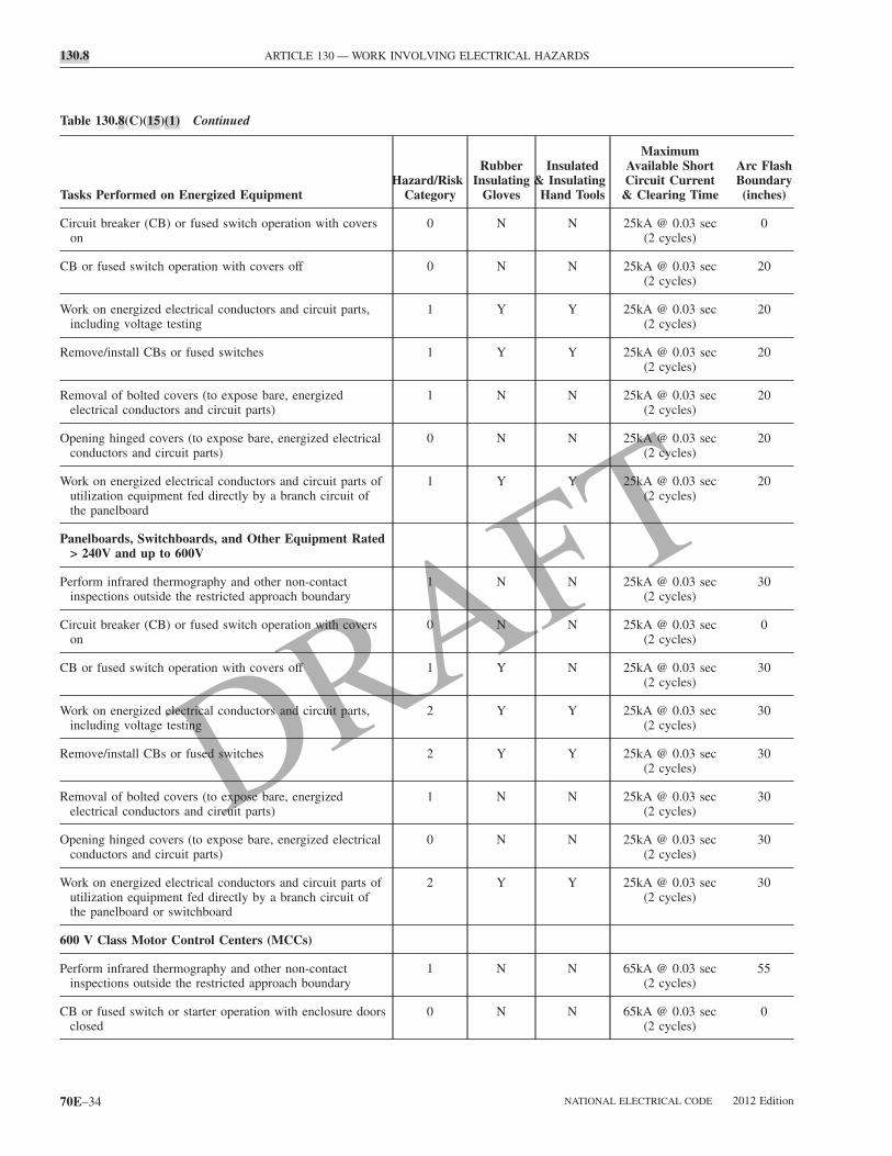
R
R
O
W
6
P
C
130.8 ARTICLE 130 — WORK INVOLVING ELECTRICAL HAZARDS
Table 130.8(C)(15)(1) Continued
Tasks Performed on Energized EquipmentHazard/Risk
Category
RubberInsulating
Gloves
Insulated& Insulating
Hand Tools
MaximumAvailable ShortCircuit Current
& Clearing Time
Arc FlashBoundary(inches)
Circuit breaker (CB) or fused switch operation with coverson
0 N N 25kA @ 0.03 sec(2 cycles)
0
CB or fused switch operation with covers off 0 N N 25kA @ 0.03 sec(2 cycles)
20
Work on energized electrical conductors and circuit parts,including voltage testing
1 Y Y 25kA @ 0.03 sec(2 cycles)
20
Remove/install CBs or fused switches 1 Y Y 25kA @ 0.03 sec(2 cycles)
20
Removal of bolted covers (to expose bare, energizedelectrical conductors and circuit parts)
1 N N 25kA @ 0.03 sec(2 cycles)
20
Opening hinged covers (to expose bare, energized electricalconductors and circuit parts)
0 N N 25kA @ 0.03 sec(2 cycles)
20
Work on energized electrical conductors and circuit parts ofutilization equipment fed directly by a branch circuit ofthe panelboard
1 Y Y 25kA @ 0.03 sec(2 cycles)
20
Panelboards, Switchboards, and Other Equipment Rated> 240V and up to 600V
Perform infrared thermography and other non-contactinspections outside the restricted approach boundary
1 N N 25kA @ 0.03 sec(2 cycles)
30
Circuit breaker (CB) or fused switch operation with coverson
0 N N 25kA @ 0.03 sec(2 cycles)
0
CB or fused switch operation with covers off 1 Y N 25kA @ 0.03 sec(2 cycles)
30
Work on energized electrical conductors and circuit parts,including voltage testing
2 Y Y 25kA @ 0.03 sec(2 cycles)
30
emove/install CBs or fused switches 2 Y Y 25kA @ 0.03 sec(2 cycles)
30
emoval of bolted covers (to expose bare, energizedelectrical conductors and circuit parts)
1 N N 25kA @ 0.03 sec(2 cycles)
30
pening hinged covers (to expose bare, energized electricalconductors and circuit parts)
0 N N 25kA @ 0.03 sec(2 cycles)
30
ork on energized electrical conductors and circuit parts ofutilization equipment fed directly by a branch circuit ofthe panelboard or switchboard
2 Y Y 25kA @ 0.03 sec(2 cycles)
30
00 V Class Motor Control Centers (MCCs)
erform infrared thermography and other non-contactinspections outside the restricted approach boundary
1 N N 65kA @ 0.03 sec(2 cycles)
55
B or fused switch or starter operation with enclosure doorsclosed
0 N N 65kA @ 0.03 sec(2 cycles)
0
NATIONAL ELECTRICAL CODE 2012 Edition70E–34
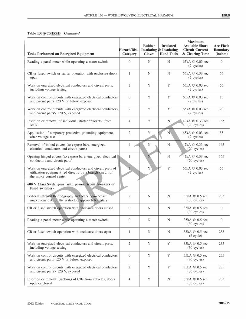
W
I
A
R
O
W
6
P
C
R
C
W
W
W
I
ARTICLE 130 — WORK INVOLVING ELECTRICAL HAZARDS 130.8
Table 130.8(C)(15)(1) Continued
Tasks Performed on Energized EquipmentHazard/Risk
Category
RubberInsulating
Gloves
Insulated& Insulating
Hand Tools
MaximumAvailable ShortCircuit Current
& Clearing Time
Arc FlashBoundary(inches)
Reading a panel meter while operating a meter switch 0 N N 65kA @ 0.03 sec(2 cycles)
0
CB or fused switch or starter operation with enclosure doorsopen
1 N N 65kA @ 0.33 sec(2 cycles)
55
Work on energized electrical conductors and circuit parts,including voltage testing
2 Y Y 65kA @ 0.03 sec(2 cycles)
55
Work on control circuits with energized electrical conductorsand circuit parts 120 V or below, exposed
0 Y Y 65kA @ 0.03 sec(2 cycles)
15
ork on control circuits with energized electrical conductorsand circuit parts> 120 V, exposed
2 Y Y 65kA @ 0.03 sec(2 cycles)
20
nsertion or removal of individual starter “buckets” fromMCC
4 Y N 42kA @ 0.33 sec(20 cycles)
165
pplication of temporary protective grounding equipment,after voltage test
2 Y N 65kA @ 0.03 sec(2 cycles)
55
emoval of bolted covers (to expose bare, energizedelectrical conductors and circuit parts)
4 N N 42kA @ 0.33 sec(20 cycles)
165
pening hinged covers (to expose bare, energized electricalconductors and circuit parts)
1 N N 42kA @ 0.33 sec(20 cycles)
165
ork on energized electrical conductors and circuit parts ofutilization equipment fed directly by a branch circuit ofthe motor control center
2 Y Y 65kA @ 0.03 sec(2 cycles)
55
00 V Class Switchgear (with power circuit breakers orfused switches)
erform infrared thermography and other non-contactinspections outside the restricted approach boundary
2 N N 35kA @ 0.5 sec(30 cycles)
235
B or fused switch operation with enclosure doors closed 0 N N 35kA @ 0.5 sec(30 cycles)
0
eading a panel meter while operating a meter switch 0 N N 35kA @ 0.5 sec(30 cycles)
0
B or fused switch operation with enclosure doors open 1 N N 35kA @ 0.5 sec(2 cycle)
235
ork on energized electrical conductors and circuit parts,including voltage testing
2 Y Y 35kA @ 0.5 sec(30 cycles)
235
ork on control circuits with energized electrical conductorsand circuit parts 120 V or below, exposed
0 Y Y 35kA @ 0.5 sec(30 cycles)
235
ork on control circuits with energized electrical conductorsand circuit parts> 120 V, exposed
2 Y Y 35kA @ 0.5 sec(30 cycles)
235
nsertion or removal (racking) of CBs from cubicles, doorsopen or closed
4 Y N 35kA @ 0.5 sec(30 cycles)
235
2012 Edition NATIONAL ELECTRICAL CODE 70E–35

A
I
N
P
C
R
C
W
130.8 ARTICLE 130 — WORK INVOLVING ELECTRICAL HAZARDS
Table 130.8(C)(15)(1) Continued
Tasks Performed on Energized EquipmentHazard/Risk
Category
RubberInsulating
Gloves
Insulated& Insulating
Hand Tools
MaximumAvailable ShortCircuit Current
& Clearing Time
Arc FlashBoundary(inches)
Application of temporary protective grounding equipmentafter voltage test
2 Y N 35kA @ 0.5 sec(30 cycles)
235
Removal of bolted covers (to expose bare, energizedelectrical conductors and circuit parts)
4 N N 35kA @ 0.5 sec(30 cycles)
235
Opening hinged covers (to expose bare, energized electricalconductors and circuit parts)
2 N N 35kA @ 0.5 sec(30 cycles)
235
Other 600 V Class (277 V through 600 V, nominal)Equipment
Lighting or small power transformers (600 V, maximum)Removal of bolted covers (to expose bare, energizedelectrical conductors and circuit parts)
2 N N 65kA @ 0.03 sec(2 cycles)
55
Opening hinged covers (to expose bare, energizedelectrical conductors and circuit parts)
1 N N 65kA @ 0.03 sec(2 cycles)
55
Work on energized electrical conductors and circuit parts,including voltage testing
2 Y Y 65kA @ 0.03 sec(2 cycles)
55
Application of temporary protective grounding equipment,after voltage test
2 Y N 65kA @ 0.03 sec(2 cycles)
55
Revenue meters (kW-hour, at primary voltage and current) –insertion or removal
2 Y N 65kA @ 0.03 sec(2 cycles)
55
Cable trough or tray cover removal or installation 1 N N 65kA @ 0.03 sec(2 cycles)
55
Miscellaneous equipment cover removal or installation 1 N N 65kA @ 0.03 sec(2 cycles)
55
Work on energized electrical conductors and circuit parts,including voltage testing
2 Y Y 65kA @ 0.03 sec(2 cycles)
55
pplication of temporary protective grounding equipment,after voltage test
2 Y N 65kA @ 0.03 sec(2 cycles)
55
nsertion or removal of plug-in devices into or frombusways
2 Y N 65kA @ 0.03 sec(2 cycles)
55
EMA E2 (fused contactor) Motor Starters, 2.3 kVthrough 7.2 kV
erform infrared thermography and other non-contactinspections outside the restricted approach boundary
3 N N 35kA @ 0.2 sec(12 cycles)
420
ontactor operation with enclosure doors closed 0 N N 35kA @ 0.2 sec(12 cycles)
420
eading a panel meter while operating a meter switch 0 N N 35kA @ 0.2 sec(12 cycles)
420
ontactor operation with enclosure doors open 2 N N 35kA @ 0.2 sec(12 cycles)
420
ork on energized electrical conductors and circuit parts,including voltage testing
4 Y Y 35kA @ 0.2 sec(12 cycles)
420
NATIONAL ELECTRICAL CODE 2012 Edition70E–36

R
O
I
M
P
C
R
C
W
W
W
I
A
R
O
ARTICLE 130 — WORK INVOLVING ELECTRICAL HAZARDS 130.8
Table 130.8(C)(15)(1) Continued
Tasks Performed on Energized EquipmentHazard/Risk
Category
RubberInsulating
Gloves
Insulated& Insulating
Hand Tools
MaximumAvailable ShortCircuit Current
& Clearing Time
Arc FlashBoundary(inches)
Work on control circuits with energized electrical conductorsand circuit parts 120 V or below, exposed
0 Y Y 35kA @ 0.2 sec(12 cycles)
420
Work on control circuits with energized electrical conductorsand circuit parts> 120 V, exposed
3 Y Y 35kA @ 0.2 sec(12 cycles)
420
Insertion or removal (racking) of starters from cubicles,doors open or closed
4 N N 35kA @ 0.2 sec(12 cycles)
420
Application of temporary protective grounding equipment,after voltage test
3 Y N 35kA @ 0.2 sec(12 cycles)
420
emoval of bolted covers (to expose bare, energizedelectrical conductors and circuit parts)
4 N N 35kA @ 0.2 sec(12 cycles)
420
pening hinged covers (to expose bare, energized electricalconductors and circuit parts)
3 N N 35kA @ 0.2 sec(12 cycles)
420
nsertion or removal (racking) of starters from cubicles ofarc-resistant construction, tested in accordance with IEEEC37.20.7, doors closed only
0 N N 35kA @ 0.2 sec(12 cycles)
0
etal Clad Switchgear, 1 kV through 38 kV
erform infrared thermography and other non-contactinspections outside the restricted approach boundary
3 N N 35kA @ 0.2 sec(12 cycles)
420
B operation with enclosure doors closed 2 N N 35kA @ 0.2 sec(12 cycles)
420
eading a panel meter while operating a meter switch 0 N N 35kA @ 0.2 sec(12 cycles)
420
B operation with enclosure doors open 4 N N 35kA @ 0.2 sec(12 cycles)
420
ork on energized electrical conductors and circuit parts,including voltage testing
4 Y Y 35kA @ 0.2 sec(12 cycles)
420
ork on control circuits with energized electrical conductorsand circuit parts 120 V or below, exposed
2 Y Y 35kA @ 0.2 sec(12 cycles)
15
ork on control circuits with energized electrical conductorsand circuit parts >120 V, exposed
4 Y Y 35kA @ 0.2 sec(12 cycles)
20
nsertion or removal (racking) of CBs from cubicles, doorsopen or closed
4 N N 35kA @ 0.2 sec(12 cycles)
420
pplication of temporary protective grounding equipment,after voltage test
4 Y N 35kA @ 0.2 sec(12 cycles)
420
emoval of bolted covers (to expose bare, energizedelectrical conductors and circuit parts)
4 N N 35kA @ 0.2 sec(12 cycles)
420
pening hinged covers (to expose bare, energized electricalconductors and circuit parts)
3 N N 35kA @ 0.2 sec(12 cycles)
420
2012 Edition NATIONAL ELECTRICAL CODE 70E–37

I
I
130.8 ARTICLE 130 — WORK INVOLVING ELECTRICAL HAZARDS
Table 130.8(C)(15)(1) Continued
Tasks Performed on Energized EquipmentHazard/Risk
Category
RubberInsulating
Gloves
Insulated& Insulating
Hand Tools
MaximumAvailable ShortCircuit Current
& Clearing Time
Arc FlashBoundary(inches)
Opening voltage transformer or control power transformercompartments
4 N N 35kA @ 0.2 sec(12 cycles)
420
Arc-Resistant Switchgear Type 1 or 2 (for clearing timesof < 0.5 sec with a perspective fault current not toexceed the arc-resistant rating of the equipment)
CB operation with enclosure door closed 0 N N 35kA @ 0.2 sec(12 cycles)
0
Insertion or removal (racking) of CBs from cubicles, doorsclosed
0 N N 35kA @ 0.2 sec(12 cycles)
0
Insertion or removal of CBs from cubicles with door open 4 N N 35kA @ 0.2 sec(12 cycles)
420
Work on control circuits with energized electrical conductorsand circuit parts 120 V or below, exposed
2 Y Y 35kA @ 0.2 sec(12 cycles)
15
Insertion or removal (racking) of ground and test devicewith door closed
0 N N 35kA @ 0.2 sec(12 cycles)
420
Insertion or removal (racking) of voltage transformers on oroff the bus door closed
0 N N 35kA @ 0.2 sec(12 cycles)
420
Other Equipment 1 kV through 38 kV
Metal-enclosed interrupter switchgear, fused or unfusedSwitch operation of arc-resistant-type construction, testedin accordance with IEEE C37.20.7, doors closed only
0 N N 35kA @ 0.2 sec(12 cycles)
0
Switch operation, doors closed 2 N N 35kA @ 0.2 sec(12 cycles)
420
Work on energized electrical conductors and circuit parts,including voltage testing
4 Y Y 35kA @ 0.2 sec(12 cycles)
420
Removal of bolted covers (to expose bare, energizedelectrical conductors and circuit parts)
4 N N 35kA @ 0.2 sec(12 cycles)
420
Opening hinged covers (to expose bare, energizedelectrical conductors and circuit parts)
3 N N 35kA @ 0.2 sec(12 cycles)
420
Outdoor disconnect switch operation (hookstick operated) 3 Y Y 35kA @ 0.2 sec(12 cycles)
420
Outdoor disconnect switch operation (gang-operated, fromgrade)
2 Y N 35kA @ 0.2 sec(12 cycles)
420
nsulated cable examination, in manhole or other confinedspace
4 Y N 35kA @ 0.2 sec(12 cycles)
420
nsulated cable examination, in open area 2 Y N 35kA @ 0.2 sec(12 cycles)
420
Notes:(1) Rubber insulating gloves are gloves rated for the maximum line-to-line voltage upon which work will be done.(2) Insulated and insulating hand tools are tools rated and tested for the maximum line-to-line voltage upon which work will be done, and aremanufactured and tested in accordance with ASTM F 1505, Standard Specification for Insulated and Insulating Hand Tools.(3) Y = yes (required), N = no (not required).(4) The use of “N” does not indicate that rubber insulating gloves, insulated and insulating hand tools are not required in all cases. Rubberinsulating gloves, insulated and insulating hand tools may be required by 130.4, 130.8 (C) (7), and 130.8(D).(5) For systems rated less than 1000 volts, the fault currents and upstream protective device clearing times are based on an 18 in. working distance.
(6) For systems rated 1 kV and greater, the Hazard/Risk Categories are based on a 36 in. working distance.NATIONAL ELECTRICAL CODE 2012 Edition70E–38
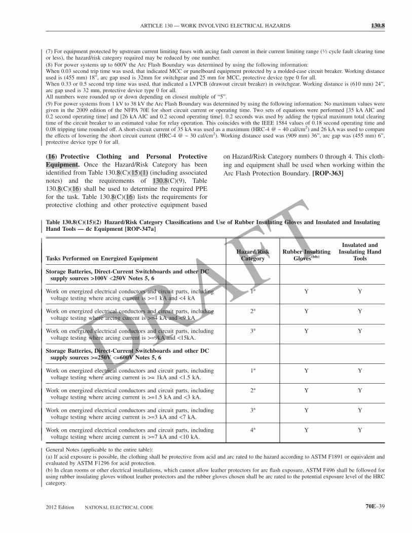
ARTICLE 130 — WORK INVOLVING ELECTRICAL HAZARDS 130.8
(7) For equipment protected by upstream current limiting fuses with arcing fault current in their current limiting range (1⁄2 cycle fault clearing timeor less), the hazard/risk category required may be reduced by one number.(8) For power systems up to 600V the Arc Flash Boundary was determined by using the following information:When 0.03 second trip time was used, that indicated MCC or panelboard equipment protected by a molded-case circuit breaker. Working distanceused is (455 mm) 18”, arc gap used is 32mm for switchgear and 25 mm for MCC, protective device type 0 for all.When 0.33 or 0.5 second trip time was used, that indicated a LVPCB (drawout circuit breaker) in switchgear. Working distance is (610 mm) 24”,arc gap used is 32 mm, protective device type 0 for all.All numbers were rounded up or down depending on closest multiple of “5”.(9) For power systems from 1 kV to 38 kV the Arc Flash Boundary was determined by using the following information: No maximum values weregiven in the 2009 edition of the NFPA 70E for short circuit current or operating time. Two sets of equations were performed [35 kA AIC and0.2 second operating time] and [26 kA AIC and 0.2 second operating time]. 0.2 seconds was used by adding the typical maximum total clearingtime of the circuit breaker to an estimated value for relay operation. This coincides with the IEEE 1584 values of 0.18 second operating time and0.08 tripping time rounded off. A short-circuit current of 35 kA was used as a maximum (HRC-4 @ ~ 40 cal/cm2) and 26 kA was used to comparethe effects of lowering the short circuit current (HRC-4 @ ~ 30 cal/cm2). Working distance used was (909 mm) 36”, arc gap was (455 mm) 6”,protective device type 0 for all.
(16) Protective Clothing and Personal ProtectiveEquipment. Once the Hazard/Risk Category has beenidentified from Table 130.8(C)(15)(1) (including associatednotes) and the requirements of 130.8(C)(9), Table130.8(C)(16) shall be used to determine the required PPEfor the task. Table 130.8(C)(16) lists the requirements forprotective clothing and other protective equipment based
Table 130.8(C)(15)(2) Hazard/Risk Category Classifications aHand Tools — dc Equipment [ROP-347a]
Tasks Performed on Energized Equipment
Storage Batteries, Direct-Current Switchboards and other DCsupply sources >100V <250V Notes 5, 6
Work on energized electrical conductors and circuit parts, includivoltage testing where arcing current is >=1 kA and <4 kA
Work on energized electrical conductors and circuit parts, includivoltage testing where arcing current is >=4 kA and <9 kA
Work on energized electrical conductors and circuit parts, includivoltage testing where arcing current is >=9kA and <15kA.
Storage Batteries, Direct-Current Switchboards and other DCsupply sources >=250V <=600V Notes 5, 6
Work on energized electrical conductors and circuit parts, includivoltage testing where arcing current is >= 1kA and <1.5 kA.
Work on energized electrical conductors and circuit parts, includivoltage testing where arcing current is >=1.5 kA and <3 kA.
Work on energized electrical conductors and circuit parts, includivoltage testing where arcing current is >=3 kA and <7 kA.
Work on energized electrical conductors and circuit parts, includivoltage testing where arcing current is >=7 kA and <10 kA.
General Notes (applicable to the entire table):(a) If acid exposure is possible, the clothing shall be protective from aevaluated by ASTM F1296 for acid protection.(b) In clean rooms or other electrical installations, which cannot allowusing rubber insulating gloves without leather protectors and the rubbe
category.2012 Edition NATIONAL ELECTRICAL CODE
on Hazard/Risk Category numbers 0 through 4. This cloth-ing and equipment shall be used when working within theArc Flash Protection Boundary. [ROP-363]
of Rubber Insulating Gloves and Insulated and Insulating
Hazard/RiskCategory
Rubber InsulatingGloves(bh)
Insulated andInsulating Hand
Tools
1a Y Y
2a Y Y
3a Y Y
1a Y Y
2a Y Y
3a Y Y
4a Y Y
arc rated to the hazard according to ASTM F1891 or equivalent and
r protectors for arc flash exposure, ASTM F496 shall be followed fors chosen shall be arc rated to the potential exposure level of the HRC
nd Use
ng
ng
ng
ng
ng
ng
ng
cid and
leather glove
70E–39
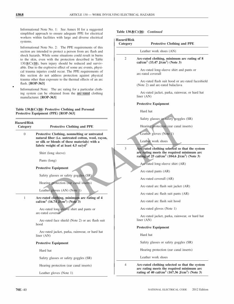
H
T
H
130.8 ARTICLE 130 — WORK INVOLVING ELECTRICAL HAZARDS
•
Informational Note No. 1: See Annex H for a suggestedsimplified approach to ensure adequate PPE for electricalworkers within facilities with large and diverse electricalsystems.
Informational Note No. 2: The PPE requirements of thissection are intended to protect a person from arc flash andshock hazards. While some situations could result in burnsto the skin, even with the protection described in Table130.8(C)(16), burn injury should be reduced and surviv-able. Due to the explosive effect of some arc events, physi-cal trauma injuries could occur. The PPE requirements ofthis section do not address protection against physicaltrauma other than exposure to the thermal effects of an arcflash. [ROP-363]
Informational Note: The arc rating for a particular cloth-ing system can be obtained from the arc rated clothingmanufacturer. [ROP-363]
Table 130.8(C)(16) Protective Clothing and PersonalProtective Equipment (PPE) [ROP-363]
azard/RiskCategory Protective Clothing and PPE
0 Protective Clothing, nonmelting or untreatednatural fiber (i.e. untreated cotton, wool, rayon,or silk or blends of these materials) with afabric weight of at least 4.5 oz/yd2
Shirt (long sleeve)
Pants (long)
Protective Equipment
Safety glasses or safety goggles (SR)
Hearing protection (ear canal inserts)
Leather gloves (AN) (Note 1)
1 Arc-rated clothing, minimum arc rating of 4cal/cm2 (16.74 J/cm2) (Note 3)
Arc-rated long-sleeve shirt and pants orarc-rated coverall
Arc-rated face shield (Note 2) or arc flash suithood
Arc-rated jacket, parka, rainwear, or hard hatliner (AN)
Protective Equipment
Hard hat
Safety glasses or safety goggles (SR)
Hearing protection (ear canal inserts)
Leather gloves (Note 1)
70E–40
able 130.8(C)(16) Continued
azard/RiskCategory Protective Clothing and PPE
Leather work shoes (AN)
2 Arc-rated clothing, minimum arc rating of 8cal/cm2 (33.47 J/cm2) (Note 3)
Arc-rated long-sleeve shirt and pants orarc-rated coverall
Arc-rated flash suit hood or arc-rated faceshield(Note 2) and arc-rated balaclava
Arc-rated jacket, parka, rainwear, or hard hatliner (AN)
Protective Equipment
Hard hat
Safety glasses or safety goggles (SR)
Hearing protection (ear canal inserts)
Leather gloves (Note 1)
Leather work shoes
3 Arc-rated clothing selected so that the systemarc rating meets the required minimum arcrating of 25 cal/cm2 (104.6 J/cm2) (Note 3)
Arc-rated long-sleeve shirt (AR)
Arc-rated pants (AR)
Arc-rated coverall (AR)
Arc-rated arc flash suit jacket (AR)
Arc-rated arc flash suit pants (AR)
Arc-rated arc flash suit hood
Arc-rated gloves (Note 1)
Arc-rated jacket, parka, rainwear, or hard hatliner (AN)
Protective Equipment
Hard hat
Safety glasses or safety goggles (SR)
Hearing protection (ear canal inserts)
Leather work shoes
4 Arc-rated clothing selected so that the systemarc rating meets the required minimum arcrating of 40 cal/cm2 (167.36 J/cm2) (Note 3)
NATIONAL ELECTRICAL CODE 2012 Edition

H
ARTICLE 130 — WORK INVOLVING ELECTRICAL HAZARDS 130.8
Table 130.8(C)(16) Continued
azard/RiskCategory Protective Clothing and PPE
Arc-rated long-sleeve shirt (AR)
Arc-rated pants (AR)
Arc-rated coverall (AR)
Arc-rated arc flash suit jacket (AR)
Arc-rated arc flash suit pants (AR)
Arc-rated arc flash suit hood
Arc-rated gloves (Note 1)
Arc-rated jacket, parka, rainwear, or hard hatliner (AN)
Protective Equipment
Hard hat
Safety glasses or safety goggles (SR)
Hearing protection (ear canal inserts)
Leather work shoes
AN = As needed (optional)AR = As requiredSR = Selection requiredNotes:(1) If rubber insulating gloves with leather protectors are required byTable 130.7(C)(9), additional leather or arc-rated gloves are not re-quired. The combination of rubber insulating gloves with leather pro-tectors satisfies the arc flash protection requirement.(2) Faceshields are to have wrap-around guarding to protect not onlythe face but also the forehead, ears, and neck or, alternatively, anarc-rated arc flash suit is required to be worn.(3) Arc rating is defined in Article 100 and can be either ATPV orEBT. ATPV is defined in ASTM F 1959, Standard Test Method forDetermining the Arc Thermal Performance Value of Materials forClothing, as the incident energy on a material or a multilayer systemof materials that results in a 50% probability that sufficient heat trans-fer through the tested specimen is predicted to cause the onset of asecond-degree skin burn injury based on the Stoll curve, cal/cm2. EBTis defined in ASTM F 1959 as the incident energy on a material ormaterial system that results in a 50% probability of breakopen. Arcrating is reported as either ATPV or EBT, whichever is the lowervalue.
(D) Other Protective Equipment.
(1) Insulated Tools and Equipment. Employees shall useinsulated tools and/or handling equipment when workinginside the Limited Approach Boundary of exposed ener-gized electrical conductors or circuit parts where tools orhandling equipment might make accidental contact. Table
130.8(C)(15)(1) provides further information for tasks that2012 Edition NATIONAL ELECTRICAL CODE
require insulated and insulating hand tools. Insulated toolsshall be protected from damage to the insulating material.
Informational Note: See 130.4(B), Shock ProtectionBoundaries.
(a) Requirements for Insulated Tools. The following re-quirements shall apply to insulated tools:(1) Insulated tools shall be rated for the voltages on which
they are used.(2) Insulated tools shall be designed and constructed for
the environment to which they are exposed and themanner in which they are used.
(3) Insulated tools and equipment shall be inspected priorto each use. The inspection shall look for damage to theinsulation or damage that may limit the tool from per-forming its intended function or could increase the po-tential for an incident (e.g., damaged tip on ascrewdriver).
(b) Fuse or Fuse Holding Equipment. Fuse or fuseholder handling equipment, insulated for the circuit volt-age, shall be used to remove or install a fuse if the fuseterminals are energized.
(c) Ropes and Handlines. Ropes and handlines usedwithin the Limited Approach Boundary of exposed ener-gized electrical conductors or circuit parts operating at 50volts or more, or used where an electrical hazard exists,shall be nonconductive.
(d) Fiberglass-Reinforced Plastic Rods. Fiberglass-reinforced plastic rod and tube used for live line tools shallmeet the requirements of applicable portions of electricalcodes and standards dealing with electrical installation re-quirements.
Informational Note: For further information concerningelectrical codes and standards dealing with installation re-quirements, refer to ASTM F 711, Standard Specificationfor Fiberglass-Reinforced Plastic (FRP) Rod and TubeUsed in Live Line Tools.
(e) Portable Ladders. Portable ladders shall have non-conductive side rails if they are used where the employee orladder could contact exposed energized electrical conduc-tors or circuit parts operating at 50 volts or more or wherean electrical hazard exists. Nonconductive ladders shallmeet the requirements of ANSI standards for ladders listedin Table 130.8(F).
(f) Protective Shields. Protective shields, protectivebarriers, or insulating materials shall be used to protecteach employee from shock, burns, or other electrically re-lated injuries while that employee is working within theLimited Approach Boundary of energized conductors orcircuit parts that might be accidentally contacted or wheredangerous electric heating or arcing might occur. Whennormally enclosed energized conductors or circuit parts are
exposed for maintenance or repair, they shall be guarded to70E–41

(wedusB
(fiaTifiedf
(eseoba
(pt
130.8 ARTICLE 130 — WORK INVOLVING ELECTRICAL HAZARDS
protect unqualified persons from contact with the energizedconductors or circuit parts.
(g) Rubber Insulating Equipment. Rubber insulatingequipment used for protection from accidental contact withenergized conductors or circuit parts shall meet the require-ments of the ASTM standards listed in Table 130.8(F).
(h) Voltage-Rated Plastic Guard Equipment. Plasticguard equipment for protection of employees from acciden-tal contact with energized conductors or circuit parts, or forprotection of employees or energized equipment or materialfrom contact with ground, shall meet the requirements ofthe ASTM standards listed in Table 130.8(F).
(i) Physical or Mechanical Barriers. Physical or me-chanical (field-fabricated) barriers shall be installed nocloser than the Restricted Approach Boundary distancegiven in Table 130.4(C)(1). While the barrier is being in-stalled, the Restricted Approach Boundary distance speci-fied in Table 130.4(C)(1) shall be maintained, or the ener-gized conductors or circuit parts shall be placed in anelectrically safe work condition.
(E) Alerting Techniques.
(1) Safety Signs and Tags. Safety signs, safety symbols,or accident prevention tags shall be used where necessaryto warn employees about electrical hazards that might en-danger them. Such signs and tags shall meet the require-ments of ANSI Z535, Series of Standards for Safety Signsand Tags, given in Table 130.8(F).
70E–42
Informational Note: Safety signs, tags, and barricadesused to identify energized“look-alike” equipment can beemployed as an additional preventive measure.
2) Barricades. Barricades shall be used in conjunctionith safety signs where it is necessary to prevent or limit
mployee access to work areas containing energized con-uctors or circuit parts. Conductive barricades shall not besed where it might cause an electrical hazard. Barricadeshall be placed no closer than the Limited Approachoundary given in Table 130.4(C)(1).
3) Attendants. If signs and barricades do not provide suf-cient warning and protection from electrical hazards, anttendant shall be stationed to warn and protect employees.he primary duty and responsibility of an attendant provid-
ng manual signaling and alerting shall be to keep unquali-ed employees outside a work area where the unqualifiedmployee might be exposed to electrical hazards. An atten-ant shall remain in the area as long as there is a potentialor employees to be exposed to the electrical hazards.
4) Look-Alike Equipment. Where work performed onquipment that is deenergized and placed in an electricallyafe condition exists in a work area with other energizedquipment that is similar in size, shape, and construction,ne of the altering methods in 130.8(E)(1), (2), or (3) shalle employed to prevent the employee from entering look-like equipment.
F) Standards for Other Protective Equipment. Otherrotective equipment required in 130.8(D) shall conform tohe standards given in Table 130.8(F).
NATIONAL ELECTRICAL CODE 2012 Edition

ARTICLE 130 — WORK INVOLVING ELECTRICAL HAZARDS 130.8
Table 130.8(F) Standards on Other Protective Equipment [ROP-383]
Subject DocumentDocument Number and
Revision
Arc Protective Blankets Standard Test Method for Determining the Protective Performanceof an Arc Protective Blanket for Electric Arc Hazards,
ASTM F2676 2009
Blankets Standard Specification for Rubber Insulating Blankets ASTM D1048 - 05
Blankets – In-service Care Standard Specification for In-Service Care of Insulating Blankets ASTM F479 - 06
Covers Standard Specification for Rubber Insulating Covers ASTM D1049 - 98(2002)e1
Fiberglass Rods -Live Line Tools Standard Specification for Fiberglass-Reinforced Plastic (FRP)Rod and Tube Used in Live Line Tools
ASTM F711 - 02(2007)
Insulated Hand Tools Standard Specification for Insulated and Insulating Hand Tools ASTM F1505 - 07
Ladders American National Standard for Ladders - Wood SafetyRequirements
ANSI A14.1-2007
American National Standard for Ladders - Fixed - SafetyRequirements
ANSI A14.3-2008
American National Standard Safety Requirements for Job MadeWooden Ladders
ANSI A14.4-2009
American National Standard for Ladders - Portable ReinforcedPlastic - Safety Requirements
ANSI A14.5-2007
Line Hose Standard Specification for Rubber Insulating Line Hose ASTM D1050 - 05e1
Line Hose and Covers – In-serviceCare
Standard Specification for In-Service Care of Insulating LineHose and Covers
ASTM F478 - 09
Plastic Guard Standard Test Methods and Specifications for ElectricallyInsulating Plastic Guard Equipment for Protection of Workers
ASTM F712 - 06
PVC Sheeting Standard Specification for PVC Insulating Sheeting ASTM F1742 - 03e1
Safety Signs and Tags Series of Standards for Safety Signs and Tags ANSI Z535 SERIES
Shield Performance on Live LineTools
Standard Test Method for Determining the Protective Performanceof a Shield Attached on Live Line Tools or on Racking Rods forElectric Arc Hazards
ASTM F2522 - 05
Temporary Protective Grounds –In-service testing
Standard Specification for In-Service Test Methods for TemporaryGrounding Jumper Assemblies Used on De-Energized ElectricPower Lines and Equipment
ASTM F2249 - 03(2009)
Temporary Protective Grounds-TestSpecification
Standard Specifications for Temporary Protective Grounds to BeUsed on De-energized Electric Power Lines and Equipment
ASTM F855 - 09
2012 Edition NATIONAL ELECTRICAL CODE 70E–43

CHAPTER 2 ARTICLE 205 — GENERAL MAINTENANCE REQUIREMENTS
Chapter 2 Safety-Related Maintenance Requirements
dm
2sd
2cm
2Pca
2sc
2p
2c(t
2si
2td
2Ebw
2c
(n
ARTICLE 200Introduction
200.1 Scope. Chapter 2 addresses the following require-ments:
(1) Chapter 2 covers practical safety-related maintenancerequirements for electrical equipment and installationsin workplaces as included in 90.2. These requirementsidentify only that maintenance directly associated withemployee safety.
(2) Chapter 2 does not prescribe specific maintenancemethods or testing procedures. It is left to the employerto choose from the various maintenance methods avail-able to satisfy the requirements of Chapter 2.
(3) For the purpose of Chapter 2, maintenance shall bedefined as preserving or restoring the condition of elec-trical equipment and installations, or parts of either, forthe safety of employees who work where exposed toelectrical hazards. Repair or replacement of individualportions or parts of equipment shall be permitted with-out requiring modification or replacement of other por-tions or parts that are in a safe condition. [ROP-385]
Informational Note: Refer to NFPA 70B, RecommendedPractice for Electrical Equipment Maintenance, andANSI/NETA MTS-2007, Standard for Maintenance TestingSpecifications for Electrical Power Distribution Equipmentand Systems, for guidance on maintenance frequency,methods, and tests. [ROP-386]
ARTICLE 205General Maintenance Requirements
205.1 Qualified Persons. Employees who perform main-tenance on electrical equipment and installations shall bequalified persons as required in Chapter 1 and shall betrained in, and familiar with, the specific maintenance pro-cedures and tests required.
205.2 Single Line Diagram. A single line diagram, whereprovided for the electrical system, shall be maintained in alegible condition and shall be kept current. [ROP-388]
205.3 General Maintenance Requirements. Overcurrentprotective devices shall be maintained in accordance with
the manufacturers’ instructions or industry consensus stan- e70E–44
ards. Maintenance, tests, and inspections shall be docu-ented. [ROP-390]
05.4 Spaces About Electrical Equipment. All workingpace and clearances required by electrical codes and stan-ards shall be maintained.
Informational Note: For further information concerningspaces about electrical equipment, see Article 105, Parts IIand III, of NFPA 70, National Electrical Code.
05.5 Grounding and Bonding. Equipment, raceway,able tray, and enclosure bonding and grounding shall beaintained to ensure electrical continuity.
05.6 Guarding of Energized Conductors and Circuitarts. Enclosures shall be maintained to guard against ac-idental contact with energized conductors and circuit partsnd other electrical hazards.
05.7 Safety Equipment. Locks, interlocks, and otherafety equipment shall be maintained in proper workingondition to accomplish the control purpose.
05.8 Clear Spaces. Access to working space and escapeassages shall be kept clear and unobstructed.
05.9 Identification of Components. Identification ofomponents, where required, and safety-related instructionsoperating or maintenance), if posted, shall be securely at-ached and maintained in legible condition.
05.10 Warning Signs. Warning signs, where required,hall be visible, securely attached, and maintained in leg-ble condition.
05.11 Identification of Circuits. Circuit or voltage iden-ification shall be securely affixed and maintained in up-ated and legible condition.
05.12 Single and Multiple Conductors and Cables.lectrical cables and single and multiple conductors shalle maintained free of damage, shorts, and ground thatould present a hazard to employees.
05.13 Flexible Cords and Cables. Flexible cords andables shall be maintained to avoid strain and damage.
1) Damaged Cords and Cables. Cords and cables shallot have worn, frayed, or damaged areas that present an
lectrical hazard to employees.NATIONAL ELECTRICAL CODE 2012 Edition

ARTICLE 230 — ROTATING EQUIPMENT 230.1
(2) Strain Relief. Strain relief of cords and cables shall bemaintained to prevent pull from being transmitted directlyto joints or terminals.
ARTICLE 210Substations, Switchgear Assemblies,Switchboards, Panelboards, MotorControl Centers, and Disconnect
Switches
210.1 Enclosures. Enclosures shall be kept free of mate-rial that would create a hazard.
210.2 Area Enclosures. Fences, physical protection, en-closures, or other protective means, where required toguard against unauthorized access or accidental contactwith exposed energized conductors and circuit parts, shallbe maintained.
210.3 Conductors. Current-carrying conductors (buses,switches, disconnects, joints, and terminations) and bracingshall be maintained to:
(1) Conduct rated current without overheating
(2) Withstand available fault current
210.4 Insulation Integrity. Insulation integrity shall bemaintained to support the voltage impressed.
210.5 Protective Devices. Protective devices shall bemaintained to adequately withstand or interrupt availablefault current.
Informational Note: Failure to properly maintain protec-tive devices can have an adverse effect on the arc flashhazard analysis incident energy values.
ARTICLE 215Premises Wiring
215.1 Covers for Wiring System Components. Coversfor wiring system components shall be in place with allassociated hardware, and there shall be no unprotectedopenings.
215.2 Open Wiring Protection. Open wiring protection,such as location or barriers, shall be maintained to prevent
accidental contact.2012 Edition NATIONAL ELECTRICAL CODE
215.3 Raceways and Cable Trays. Raceways and cabletrays shall be maintained to provide physical protection andsupport for conductors.
ARTICLE 220Controller Equipment
220.1 Scope. This article shall apply to controllers, includ-ing electrical equipment that governs the starting, stopping,direction of motion, acceleration, speed, and protection ofrotating equipment and other power utilization apparatus inthe workplace.
220.2 Protection and Control Circuitry. Protection andcontrol circuitry used to guard against accidental contactwith energized conductors and circuit parts and to preventother electrical or mechanical hazards shall be maintained.
ARTICLE 225Fuses and Circuit Breakers
225.1 Fuses. Fuses shall be maintained free of breaks orcracks in fuse cases, ferrules, and insulators. Fuse clipsshall be maintained to provide adequate contact with fuses.Fuseholders for current-limiting fuses shall not be modifiedto allow the insertion of fuses that are not current-limiting.
225.2 Molded-Case Circuit Breakers. Molded-case cir-cuit breakers shall be maintained free of cracks in cases andcracked or broken operating handles.
225.3 Circuit Breaker Testing After Electrical Faults[ROP-400]. Circuit breakers that interrupt faults approach-ing their interrupting ratings shall be inspected and tested inaccordance with the manufacturer’s instructions.
ARTICLE 230Rotating Equipment
230.1 Terminal Boxes. Terminal chambers, enclosures,and terminal boxes shall be maintained to guard againstaccidental contact with energized conductors and circuit
parts and other electrical hazards.70E–45

(
(
2sta
2w[
2Tct
(
(
(
(
(
2aes
230.2 ARTICLE 250 — PERSONAL SAFETY AND PROTECTIVE EQUIPMENT
•
230.2 Guards, Barriers, and Access Plates. Guards, bar-riers, and access plates shall be maintained to prevent em-ployees from contacting moving or energized parts.
ARTICLE 235Hazardous (Classified) Locations
235.1 Scope. This article covers maintenance requirementsin those areas identified as hazardous (classified) locations.
Informational Note: These locations need special types ofequipment and installation to ensure safe performance un-der conditions of proper use and maintenance. It is impor-tant that inspection authorities and users exercise more thanordinary care with regard to installation and maintenance.The maintenance for specific equipment and materials iscovered elsewhere in Chapter 2 and is applicable to hazard-ous (classified) locations. Other maintenance will ensurethat the form of construction and of installation that makesthe equipment, and materials suitable for the particular lo-cation are not compromised.
The maintenance needed for specific hazardous (classi-fied) locations depends on the classification of the specificlocation. The design principles and equipment characteris-tics, for example, use of positive pressure ventilation, ex-plosionproof, nonincendive, intrinsically safe, and purgedand pressurized equipment, that were applied in the instal-lation to meet the requirements of the area classificationmust also be known. With this information, the employerand the inspection authority are able to determine whetherthe installation as maintained has retained the conditionnecessary for a safe workplace.
235.2 Maintenance Requirements for Hazardous (Clas-sified) Locations. Equipment and installations in these lo-cations shall be maintained such that the following apply:
(1) No energized parts are exposed.
Exception to (1): Intrinsically safe and nonincendivecircuits.
(2) There are no breaks in conduit systems, fittings, orenclosures from damage, corrosion, or other causes.
(3) All bonding jumpers are securely fastened and intact.
(4) All fittings, boxes, and enclosures with bolted covershave all bolts installed and bolted tight.
(5) All threaded conduit shall be wrenchtight and enclo-sure covers shall be tightened in accordance with themanufacturer’s instructions.
(6) There are no open entries into fittings, boxes, or enclo-sures that would compromise the protection character-istics.
(7) All close-up plugs, breathers, seals, and drains are se-
curely in place.70E–46
8) Marking of luminaires (lighting fixtures) for maximumlamp wattage and temperature rating is legible and notexceeded.
9) Required markings are secure and legible.
ARTICLE 240Batteries and Battery Rooms
40.1 Ventilation. Ventilation systems, forced or natural,hall be maintained to prevent buildup of explosive mix-ures. This maintenance shall include a functional test ofny associated detection and alarm systems.
40.2 Eye and Body Wash Apparatus. Eye and bodyash apparatus shall be maintained in operable condition.
ROP-446]
ARTICLE 245Portable Electric Tools and Equipment
45.1 Maintenance Requirements for Portable Electricools and Equipment. Attachment plugs, receptacles,over plates, and cord connectors shall be maintained suchhat the following apply:
1) There are no breaks, damage, or cracks exposing ener-gized conductors and circuit parts.
2) There are no missing cover plates.
3) Terminations have no stray strands or loose terminals.
4) There are no missing, loose, altered, or damagedblades, pins, or contacts.
5) Polarity is correct.
ARTICLE 250Personal Safety and Protective
Equipment
50.1 Maintenance Requirements for Personal Safetynd Protective Equipment. Personal safety and protectivequipment such as the following shall be maintained in aafe working condition:
(1) Grounding equipment
(2) Hot sticks
NATIONAL ELECTRICAL CODE 2012 Edition

ARTICLE 250 — PERSONAL SAFETY AND PROTECTIVE EQUIPMENT 250.3
(3) Rubber gloves, sleeves, and leather protectors
(4) Voltage test indicators
(5) Blanket and similar insulating equipment
(6) Insulating mats and similar insulating equipment
(7) Protective barriers
(8) External circuit breaker rack-out devices
(9) Portable lighting units
(10) Safety grounding equipment
(11) Dielectric footwear
(12) Protective clothing
(13) Bypass jumpers
(14) Insulated and insulating hand tools
250.2 Inspection and Testing of Protective Equipmentand Protective Tools.
(A) Visual. Safety and protective equipment and protectivetools shall be visually inspected for damage and defectsbefore initial use and at intervals thereafter, as service con-ditions require, but in no case shall the interval exceed 1year, unless specified otherwise by the respective ASTMstandards.
(B) Testing. The insulation of protective equipment andprotective tools, such as items (1) through (14) of 250.1,shall be verified by the appropriate test and visual inspec-tion to ascertain that insulating capability has been retained
before initial use, and at intervals thereafter, as service con-2012 Edition NATIONAL ELECTRICAL CODE
ditions and applicable standards and instructions require,but in no case shall the interval exceed 3 years, unlessspecified otherwise by the respective ASTM standards.
250.3 Safety Grounding Equipment.
(A) Visual. Personal protective ground cable sets shall beinspected for cuts in the protective sheath and damage tothe conductors. Clamps and connector strain relief devicesshall be checked for tightness. These inspections shall bemade at intervals thereafter as service conditions require,but in no case shall the interval exceed 1 year.
(B) Testing. Prior to being returned to service, temporaryprotective grounding equipment that has been repaired ormodified shall be tested. [ROP-406]
Informational Note: Guidance for inspecting and testingsafety grounds is provided in ASTM F 2249, StandardSpecification for In-Service Test Methods for TemporaryGrounding Jumper Assemblies Used on De-Energized Elec-tric Power Lines and Equipment.
(C) Grounding and Testing Devices. Grounding and test-ing devices shall be stored in a clean and dry area. Ground-ing and testing devices shall be properly inspected andtested before each use.
Informational Note: Guidance for testing of groundingand testing devices is provided in Section 9.5 of IEEEC37.20.6-1997, Standard for 4.76 kV to 38 kV-RatedGround and Test Devices Used in Enclosures.
70E–47

CHAPTER 3 ARTICLE 310 — SAFETY-RELATED WORK PRACTICES FOR ELECTROLYTIC CELLS
Chapter 3 Safety Requirements for Special Equipment
StSdo
3
(se11
(testw
3
(
(ketsta
(
(
(t
(
(ot
(a
ARTICLE 300Introduction
300.1 Scope. Chapter 3 covers special electrical equipmentin the workplace and modifies the general requirements ofChapter 1.
300.2 Responsibility. The employer shall provide safety-related work practices and employee training. The em-ployee shall follow those work practices.
300.3 Organization. Chapter 3 of this standard is dividedinto articles. Article 300 applies generally. Article 310 ap-plies to electrolytic cells. Article 320 applies to batteriesand battery rooms. Article 330 applies to lasers. Article 340applies to power electronic equipment. Article 350 appliesto research and development (R&D) laboratories. [ROP-408]
Informational Note: The NFPA 70E Technical Committeemight develop additional chapters for other types of specialequipment in the future.
ARTICLE 310Safety-Related Work Practices for
Electrolytic Cells
310.1 Scope. The requirements of this chapter shall applyto the electrical safety–related work practices used in thetypes of electrolytic cell areas.
Informational Note No. 1: See Annex L for a typical ap-plication of safeguards in the cell line working zone.
Informational Note No. 2: For further information aboutelectrolytic cells, see NFPA 70, National Electrical Code,Article 668.
310.2 Definitions. For the purposes of this chapter, thefollowing definitions shall apply.
Battery Effect. A voltage that exists on the cell line afterthe power supply is disconnected.
Informational Note: Electrolytic cells could exhibit char-acteristics similar to an electrical storage battery, and thus ahazardous voltage could exist after the power supply is
disconnected from the cell line. p70E–48
afeguarding. Safeguards for personnel include the consis-ent administrative enforcement of safe work practices.afeguards include training in safe work practices, cell lineesign, safety equipment, personal protective equipment,perating procedures, and work checklists.
10.3 Safety Training.
A) General. The training requirements of this chapterhall apply to employees who are exposed to the risk oflectrical hazard in the cell line working zone defined in10.2 and shall supplement or modify the requirements of20.1, 130.2, 130.3, and 130.6.
B) Training Requirements. Employees shall be trainedo understand the specific hazards associated with electricalnergy on the cell line. Employees shall be trained inafety-related work practices and procedural requirementso provide protection from the electrical hazards associatedith their respective job or task assignment.
10.4 Employee Training.
A) Qualified Persons.
1) Training. Qualified persons shall be trained andnowledgeable in the operation of cell line working zonequipment and specific work methods and shall be trainedo avoid the electrical hazards that are present. Such per-ons shall be familiar with the proper use of precautionaryechniques and personal protective equipment. Training forqualified person shall include the following:
1) The skills and techniques to avoid dangerous contactwith hazardous voltages between energized surfacesand between energized surfaces and grounded equip-ment, other grounded objects, or the earth itself. Skillsand techniques might include temporarily insulating orguarding parts to permit the employee to work on en-ergized parts. [ROP-410]
2) The method of determining the cell line working zonearea boundaries.
2) Qualified Persons. Qualified persons shall be permit-ed to work within the cell line working zone.
B) Unqualified Persons.
1) Training. Unqualified persons shall be trained to rec-gnize electrical hazards to which they may be exposed andhe proper methods of avoiding the hazards.
2) In Cell Line Working Zone. When there is a need forn unqualified person to enter the cell line working zone to
erform a specific task, that person shall be advised by theNATIONAL ELECTRICAL CODE 2012 Edition

ARTICLE 310 — SAFETY-RELATED WORK PRACTICES FOR ELECTROLYTIC CELLS 310.5
designated qualified person in charge of the possible haz-ards to ensure the unqualified person is safeguarded.
310.5 Safeguarding of Employees in the Cell LineWorking Zone.
(A) General. Operation and maintenance of electrolyticcell lines may require contact by employees with exposedenergized surfaces such as buses, electrolytic cells, andtheir attachments. The approach distances referred to inTable 130.4(C)(1) shall not apply to work performed byqualified persons in the cell line working zone. Safeguardssuch as safety-related work practices and other safeguardsshall be used to protect employees from injury while work-ing in the cell line working zone. These safeguards shall beconsistent with the nature and extent of the related electri-cal hazards. Safeguards might be different for energizedcell lines and deenergized cell lines. Hazardous battery ef-fect voltages shall be dissipated to consider a cell line deen-ergized.
Informational Note No. 1: Exposed energized surfacesmight not establish a hazardous condition. A hazardouselectrical condition is related to current flow through thebody causing shock and arc flash burns and arc blasts.Shock is a function of many factors, including resistancethrough the body and through skin, of return paths, of pathsin parallel with the body, and of system voltages. Arc flashburns and arc blasts are a function of the current availableat the point involved and the time of arc exposure.
Informational Note No. 2: A cell line or group of cell linesoperated as a unit for the production of a particular metal,gas, or chemical compound might differ from other celllines producing the same product because of variations inthe particular raw materials used, output capacity, use ofproprietary methods or process practices, or other modify-ing factors. Detailed standard electrical safety-related workpractice requirements could become overly restrictive with-out accomplishing the stated purpose of Chapter 1 of thisstandard.
(B) Signs. Permanent signs shall clearly designate electro-lytic cell areas.
(C) Electrical Arc Flash Hazard Analysis. The require-ments of 130.5, Arc Flash Hazard Analysis, shall not applyto electrolytic cell line work zones.
(1) Arc Flash Hazard Analysis Procedure. Each task per-formed in the electrolytic cell line working zone shall beanalyzed for the risk of arc flash hazard injury. If there isrisk of personal injury, appropriate measures shall be takento protect persons exposed to the arc flash hazards. Thesemeasures shall include one or more of the following:
(1) Provide appropriate personal protective equipment [see310.5(D)(2)] to prevent injury from the arc flash haz-ard.
(2) Alter work procedures to eliminate the possibility of
the arc flash hazard.2012 Edition NATIONAL ELECTRICAL CODE
(3) Schedule the task so that work can be performed whenthe cell line is deenergized.
(2) Routine Tasks. Arc flash hazard risk analysis shall bedone for all routine tasks performed in the cell line workzone. The results of the arc flash hazard analysis shall beused in training employees in job procedures that minimizethe possibility of arc flash hazards. The training shall beincluded in the requirements of 310.3.
(3) Nonroutine Tasks. Before a nonroutine task is per-formed in the cell line working zone, an arc flash hazardrisk analysis shall be done. If an arc flash hazard is a pos-sibility during nonroutine work, appropriate instructionsshall be given to employees involved on how to minimizethe possibility of a hazardous arc flash.
(4) Arc Flash Hazards. If the possibility of an arc flashhazard exists for either routine or nonroutine tasks, employ-ees shall use appropriate safeguards.
(D) Safeguards. Safeguards shall include one or a combi-nation of the following means.
(1) Insulation. Insulation shall be suitable for the specificconditions, and its components shall be permitted to in-clude glass, porcelain, epoxy coating, rubber, fiberglass,plastic, and when dry, such materials as concrete, tile,brick, and wood. Insulation shall be permitted to be appliedto energized or grounded surfaces.
(2) Personal Protective Equipment. Personal protectiveequipment shall provide protection from hazardous electri-cal conditions. Personal protective equipment shall includeone or more of the following as determined by authorizedmanagement:
(1) Shoes, boots, or overshoes for wet service
(2) Gloves for wet service
(3) Sleeves for wet service
(4) Shoes for dry service
(5) Gloves for dry service
(6) Sleeves for dry service
(7) Electrically insulated head protection
(8) Protective clothing
(9) Eye protection with nonconductive frames
(10) Faceshield (polycarbonate or similar nonmelting type)
a. Standards for Personal Protective Equipment. Per-sonal and other protective equipment shall be ap-propriate for conditions, as determined by autho-rized management, and shall not be required tomeet the equipment standards in 130.8(C)(14)through 130.8(F) and in Table 130.8(C)(14) andTable 130.8(F).
b. Testing of Personal Protective Equipment. Per-
sonal protective equipment shall be verified with70E–49

Ca
(eu
(
(
(
(
(ioie
(tc
3
(qemNtN
(emEsl
(citoc
310.6 ARTICLE 310 — SAFETY-RELATED WORK PRACTICES FOR ELECTROLYTIC CELLS
regularity and by methods that are consistent withthe exposure of employees to hazardous electricalconditions.
(3) Barriers. Barriers shall be devices that prevent contactwith energized or grounded surfaces that could present ahazardous electrical condition.
(4) Voltage Equalization. Voltage equalization shall bepermitted by bonding a conductive surface to an electricallyenergized surface, either directly or through a resistance, sothat there is insufficient voltage to create an electrical haz-ard.
(5) Isolation. Isolation shall be the placement of equip-ment or items in locations such that employees are unableto simultaneously contact exposed conductive surfaces thatcould present a hazardous electrical condition.
(6) Safe Work Practices. Employees shall be trained insafe work practices. The training shall include why thework practices in a cell line working zone are differentfrom similar work situations in other areas of the plant.Employees shall comply with established safe work prac-tices and the safe use of protective equipment.
(a) Attitude Awareness. Safe work practice trainingshall include attitude awareness instruction. Simultaneouscontact with energized parts and ground can cause seriouselectrical shock. Of special importance is the need to beaware of body position where contact may be made withenergized parts of the electrolytic cell line and groundedsurfaces.
(b) Bypassing of Safety Equipment. Safe work prac-tice training shall include techniques to prevent bypassingthe protection of safety equipment. Clothing may bypassprotective equipment if the clothing is wet. Trouser legsshould be kept at appropriate length, and shirt sleevesshould be a good fit so as not to drape while reaching.Jewelry and other metal accessories that may bypass pro-tective equipment shall not be worn while working in thecell line working zone.
(7) Tools. Tools and other devices used in the energizedcell line work zone shall be selected to prevent bridgingbetween surfaces at hazardous potential difference.
Informational Note: Tools and other devices of magneticmaterial could be difficult to handle in energized cells’ ar-eas due to their strong dc magnetic fields.
(8) Portable Cutout Type Switches. Portable cell cutoutswitches that are connected shall be considered as ener-gized and as an extension of the cell line working zone.Appropriate procedures shall be used to ensure proper cut-out switch connection and operation.
(9) Cranes and Hoists. Cranes and hoists shall meet the
requirements of 668.32 of NFPA 70, National Electrical p70E–50
ode. Insulation required for safeguarding employees, suchs insulated crane hooks, shall be periodically tested.
10) Attachments. Attachments that extend the cell linelectrical hazards beyond the cell line working zone shalltilize one or more of the following:
1) Temporary or permanent extension of the cell lineworking zone
2) Barriers
3) Insulating breaks
4) Isolation
11) Pacemakers and Metallic Implants. Employees withmplanted pacemakers, ferromagnetic medical devices, orther electronic devices vital to life shall not be permittedn cell areas unless written permission is obtained from themployee’s physician.
Informational Note: The American Conference of Govern-ment Industrial Hygienists (ACGIH) recommends that per-sons with implanted pacemakers should not be exposed tomagnetic flux densities above 10 gauss.
12) Testing. Equipment safeguards for employee protec-ion shall be tested to ensure they are in a safe workingondition.
10.6 Portable Tools and Equipment.
Informational Note: The order of preference for the en-ergy source for portable handheld equipment is consideredto be: (1) battery powered, (2) pneumatic, (3) a portablegenerator, (4) a nongrounded–type receptacle connected toan ungrounded source.
A) Portable Electrical Equipment. The grounding re-uirements of 110.4(B)(2) shall not be permitted within annergized cell line working zone. Portable electrical equip-ent shall meet the requirements of 668.20 of NFPA 70,ational Electrical Code. Power supplies for portable elec-
ric equipment shall meet the requirements of 668.21 ofFPA 70, National Electrical Code.
B) Auxiliary Nonelectric Connections. Auxiliary non-lectric connections such as air, water, and gas hoses shalleet the requirements of 668.31 of NFPA 70, Nationallectrical Code. Pneumatic-powered tools and equipmenthall be supplied with nonconductive air hoses in the celline working zone.
C) Welding Machines. Welding machine frames shall beonsidered at cell potential when within the cell line work-ng zone. Safety-related work practices shall require thathe cell line not be grounded through the welding machiner its power supply. Welding machines located outside theell line working zone shall be barricaded to prevent em-
loyees from touching the welding machine and groundNATIONAL ELECTRICAL CODE 2012 Edition

ARTICLE 320 — SAFETY REQUIREMENTS RELATED TO BATTERIES AND BATTERY ROOMS 320.3
simultaneously where the welding cables are in the cell lineworking zone.
(D) Portable Test Equipment. Test equipment in the cellline working zone shall be suitable for use in areas of largemagnetic fields and orientation.
Informational Note: Test equipment that is not suitable foruse in such magnetic fields could result in an incorrectresponse. When such test equipment is removed from thecell line working zone, its performance might return tonormal, giving the false impression that the results werecorrect.
ARTICLE 320Safety Requirements Related to Batteries
and Battery Rooms
320.1 Scope. This article covers electrical safety require-ments for the practical safeguarding of employees whileworking with exposed stationary storage batteries that ex-ceed 50 volts, nominal. [ROP-418]
Informational Note: For additional information on safetybest practices while working on stationary batteries, see thefollowing documents:
(1) NFPA 1, Fire Code, 2009 Chapter 52, Stationary Stor-age Battery Systems
(2) NFPA 70, National Electrical Code, Article 480, Stor-age Batteries, 2008
(3) IEEE Std. 450, IEEE Recommended Practice forMaintenance, Testing, and Replacement of VentedLead-Acid Batteries for Stationary Applications, 2002
(4) IEEE Std. 937, Recommended Practice for Installa-tion and Maintenance of Lead-Acid Batteries for Pho-tovoltaic Systems, 2007
(5) IEEE 1106, IEEE Recommended Practice for Instal-lation, Maintenance, Testing, and Replacement ofVented Nickel-Cadmium Batteries for Stationary Ap-plications, 2002
(6) IEEE 1184, IEEE Guide for Batteries for Uninterrupt-ible Power Supply Systems, 2006
(7) IEEE 1188, IEEE Recommended Practice for Mainte-nance, Testing, and Replacement of Valve RegulatedLead-Acid (VRLA) Batteries for Stationary Applica-tions, 2005
(8) IEEE Standard 1657, Recommended Practice for Per-sonnel Qualifications for Installation and Mainte-nance of Stationary Batteries, 2009
(9) OSHA 29 CFR 1910.305(j)(7), “Storage batteries”(10) OSHA 29 CFR 1926.441, “Batteries and battery
charging”(11) DHHS (NIOSH) Publication No. 94-110, Applications
Manual for the Revised NIOSH Lifting Equation,1994
[ROP-419, ROP-420]
2012 Edition NATIONAL ELECTRICAL CODE
320.2 Definitions [ROP-432].
Authorized Personnel. The person in charge of the pre-mises, or other persons appointed or selected by the personin charge of the premises, to perform certain duties associ-ated with stationary storage batteries. [ROP-427]
Battery. A system consisting of two or more electrochemi-cal cells connected in series or parallel and capable of stor-ing electrical energy received and which can give it back byreconversion. [ROP-428]
Battery Room. A room specifically intended for the instal-lation of batteries that have no other protective enclosure.[ROP-429]
Cell. The basic electrochemical unit, characterized by ananode and a cathode used to receive, store, and deliverelectrical energy. [ROP-430]
Electrolyte. A solid, liquid, or aqueous immobilized liquidmedium that provides the ion transport mechanism betweenthe positive and negative electrodes of a cell. [ROP-433]
Nominal Voltage. The value assigned to a cell or battery ofa given voltage class for the purpose of convenient desig-nation; the operating voltage of the cell or system may varyabove or below this value. [ROP-439]
Pilot Cell. One or more cells chosen to represent the oper-ating parameters of the entire battery (sometimes called“temperature reference” cell). [ROP-440]
Prospective Fault Current. The highest level of fault cur-rent that can occur at a point on a circuit. This is the faultcurrent that can flow in the event of a zero impedanceshort-circuit and if no protection devices operate.
Valve-Regulated Lead Acid (VRLA) Cell. A lead-acidcell that is sealed with the exception of a valve that opensto the atmosphere when the internal pressure in the cellexceeds atmospheric pressure by a pre-selected amount,and which provides a means for recombination of internallygenerated oxygen and the suppression of hydrogen gas evo-lution to limit water consumption. [ROP-442]
Vented Cell. A type of cell in which the products of elec-trolysis and evaporation are allowed to escape freely intothe atmosphere as they are generated. (Also called “floodedcell”). [ROP-444]
320.3 Safety Procedures.
(A) General Safety Hazards.
(1) Battery Room or Enclosure Requirements. [ROP-459].
(a) Personnel Access to Energized Batteries. Each bat-tery room or battery enclosure shall be accessible only to
authorized personnel. [ROP-417] [ROP-460]70E–51

(
(ti
c
a
da
([an
h
h
[
(
(tsv
(sl
320.3 ARTICLE 320 — SAFETY REQUIREMENTS RELATED TO BATTERIES AND BATTERY ROOMS
(b) Illumination. Work on battery systems shall only beperformed if lighting is sufficient for the employee to readnecessary documents and to safely perform the work.[ROP-472]
(2) Apparel. Personnel shall not wear electrically conduc-tive objects such as jewelry while working on a batterysystem. [ROP-417]
(3) Abnormal Battery Conditions. Alarms for earlywarning of the following abnormal conditions of batteryoperation, if present shall be tested yearly for the following.[ROP-455](1) For vented cells
a. Overvoltageb. Undervoltagec. Overcurrentd. Ground fault [ROP-455]
(2) For VRLA cells
a. Overvoltageb. Undervoltagec. Overcurrentd. Ground faulte. Over-temperature, as measured at the pilot cell
[ROP-455]
(4) Hazard Warning. [ROP-485].
(a) Marking. Warning notices indicating the batteryvoltage and the prospective short-circuit current of the in-stallation shall be displayed. [ROP-485]
(b) Warning Signs. The following warnings shall beposted in appropriate locations.
(1) Electrical hazard warning indicating the shock hazarddue to battery voltage and the arc hazard due to theprospective short-circuit current.
(2) Chemical hazard warning:
a. indicating the potential presence of explosive gas(when applicable to the battery type);
b. prohibiting open flame and smoking;c. warning of the danger of chemical burns from
the electrolyte (when applicable to the batterytype); and
d. applicable to the worst case when multiple bat-tery types are installed in the same space
(3) Notice for personnel to use and wear protective equip-ment and apparel appropriate to the aproach boundaryfor the battery.
(4) Notice prohibiting access to unauthorized personnel[ROP-485]
Informational Note: Because internal resistance and/orprospective short-circuit are not always provided on batterycontainer labels or data sheets, and because many variables
can be introduced into a battery layout, the battery manu-70E–52
facturer should be consulted for accurate data. Variablescan include, but are not limited to:
(1) series connections(2) parallel connections(3) charging methodology(4) temperature(5) charge status(6) dc distribution cable size and length [ROP-417]
B) Electrolyte hazards [ROP-486].
1) Batteries with Liquid Electrolyte. The following pro-ective equipment shall be available to employees perform-ng any type of service on a battery with liquid electrolyte:
(a) Goggles and face shield appropriate for the electri-al hazard and the chemical hazard.
(b) Gloves and aprons appropriate for the chemicalnd electrical hazards.
(c) Portable or stationary water facilities for quickrenching or flushing of the eyes and body within the workrea. [ROP-486]
2) Batteries with Solid or Immobilized ElectrolyteROP-486] . The following protective equipment shall bevailable to employees performing any type of service on aonspillable battery with solid or immobilized electrolyte:
(a) Goggles or face shield appropriate for the electricalazard
(b) Gloves appropriate for the electrical and chemicalazards
(c) Protective clothing appropriate for electrical hazardROP-486] [ROP-417]
C) Testing Maintenance and Operation.
1) Battery Short-Circuit Current. The battery manufac-urer shall be consulted regarding the sizing of the batteryhort-circuit protection and for battery short circuit currentalues. [ROP-449]
2) DC Ground-Fault Detection. Ground-fault detectionhall be based on the type of dc grounding systems uti-ized. [ROP-453]
Informational Note: A dc grounding system can be one offour types: [ROP-453]
(1) Type 1 — Ungrounded. An ungrounded dc system isone in which neither pole of the battery is connected toground. Work on such a system is normally carried outwith the battery isolated from the battery charger. If anintentional ground is placed at one end of the battery,an increased shock hazard would exist between the op-posite end of the battery and ground. Also, if anotherground develops within the system (e.g., dirt and acidtouching the battery rack), it can create a short circuitthat could cause a fire. An ungrounded dc system istypically equipped with an alarm to indicate the pres-
ence of a ground fault. [ROP-453]NATIONAL ELECTRICAL CODE 2012 Edition

ARTICLE 330 — SAFETY-RELATED WORK PRACTICES FOR USE OF LASERS 330.3
(2) Type 2 — solid ground. A solidly grounded dc systemis one in which either the positive or negative pole ofthe battery is connected directly to ground. [ROP-453]
(3) Type 3 — resistance ground. A resistance groundeddc system is a variation of a Type 1 system in whichthe midpoint of the battery is connected to groundthrough a resistance.The resistance is typically used toenable operation of an alarm ground fault alarm sys-tem. [ROP-453]
(4) Type 4 — tapped solid ground. A tapped solid groundis one in which ground is connected either at the centerpoint or at another point to suit the load system.[ROP-453]
(3) Tools and Equipment. [ROP-487].
(a) Tools and equipment for work on batteries shall beequipped with handles listed as insulated for the maximumworking voltage [ROP-487]
(b) Battery terminals and all electrical conductors shallbe kept clear of unintended contact with tools, test equip-ment, liquid containers, and other foreign objects.
(D) Cell Flame Arresters and Cell Ventilation. [ROP-446]. Battery cell ventilation openings shall be unob-structed, and cell flame arresters shall be maintained.[ROP-446]
(E) Fire Hazards. Battery cell flame arresters shall be in-spected for proper installation and unobstructed ventilation.[ROP-417]
(F) Handling Hazards. [ROP-417]. .
(1) When handling battery containers, personnel shall notbe exposed to a NIOSH lifting index greater than 3.0[ROP-417]
(2) Lifting devices of adequate capacity shall be used forloads greater than 45 lbs (21.5kg) [ROP-417]
(3) Lifting harnesses or devices shall be used when de-signed by the battery manufacturer for specific batterytypes. [ROP-417]
ARTICLE 330Safety-Related Work Practices for Use of
Lasers
330.1 Scope. The requirements of this article shall apply tothe use of lasers in the laboratory and the workshop.
330.2 Definitions. For the purposes of this article, the fol-
lowing definitions shall apply.2012 Edition NATIONAL ELECTRICAL CODE
Fail Safe. The design consideration in which failure of acomponent does not increase the hazard. In the failuremode, the system is rendered inoperative or nonhazardous.
Fail Safe Safety Interlock. An interlock that in the failuremode does not defeat the purpose of the interlock, for ex-ample, an interlock that is positively driven into the offposition as soon as a hinged cover begins to open, or beforea detachable cover is removed, and that is positively held inthe off position until the hinged cover is closed or the de-tachable cover is locked in the closed position.
Laser. Any device that can be made to produce or amplifyelectromagnetic radiation in the wavelength range from 100nm to 1 mm primarily by the process of controlled stimu-lated emission.
Laser Energy Source. Any device intended for use in con-junction with a laser to supply energy for the excitation ofelectrons, ions, or molecules. General energy sources, suchas electrical supply services or batteries, shall not be con-sidered to constitute laser energy sources.
Laser Product. Any product or assembly of componentsthat constitutes, incorporates, or is intended to incorporate alaser or laser system.
Laser Radiation. All electromagnetic radiation emitted bya laser product between 100 nm and 1 mm that is producedas a result of a controlled stimulated emission.
Laser System. A laser in combination with an appropriatelaser energy source with or without additional incorporatedcomponents.
330.3 Safety Training.
(A) Personnel to Be Trained. Employers shall providetraining for all operator and maintenance personnel.
(B) Scope of Training. The training shall include, but isnot limited to, the following:
(1) Familiarization with laser principles of operation, lasertypes, and laser emissions
(2) Laser safety, including the following:
(1) System operating procedures(2) Hazard control procedures(3) The need for personnel protection(4) Accident reporting procedures(5) Biological effects of the laser upon the eye and the
skin(6) Electrical and other hazards associated with the
laser equipment, including the following:a. High voltages (> 1 kV) and stored energy in the capaci-
tor banksb. Circuit components, such as electron tubes, with anode
voltages greater than 5 kV emitting X-rays
70E–53

(
(
(
(
(
3l
Ret
3gr
3se
(
(
3Blm
(
330.4 ARTICLE 340 — SAFETY-RELATED WORK PRACTICES: POWER ELECTRONIC EQUIPMENT
c. Capacitor bank explosionsd. Production of ionizing radiatione. Poisoning from the solvent or dye switching liquids or
laser mediaf. High sound intensity levels from pulsed lasers
(C) Proof of Qualification. Proof of qualification of thelaser equipment operator shall be available and in posses-sion of the operator at all times.
330.4 Safeguarding of Employees in the Laser Operat-ing Area.
(A) Eye Protection. Employees shall be provided with eyeprotection as required by federal regulation.
(B) Warning Signs. Warning signs shall be posted at theentrances to areas or protective enclosures containing laserproducts.
(C) Master Control. High power laser equipment shallinclude a key-operated master control.
(D) High-power laser equipment shall include a failsafelaser radiation emission audible and visible warning whenit is switched on or if the capacitor banks are charged.
(E) Beam shutters or caps shall be utilized, or the laserswitched off, when laser transmission is not required. Thelaser shall be switched off when unattended for 30 minutesor more.
(F) Laser beams shall not be aimed at employees.
(G) Laser equipment shall bear a label indicating its maxi-mum output.
(H) Personnel protective equipment shall be provided forusers and operators of high-power laser equipment.
330.5 Employee Responsibility. Employees shall be re-sponsible for the following:
(1) Obtaining authorization for laser use
(2) Obtaining authorization for being in a laser operatingarea
(3) Observing safety rules
(4) Reporting laser equipment failures and accidents to theemployer
ARTICLE 340Safety-Related Work Practices: Power
Electronic Equipment
340.1 Scope. This article shall apply to safety-related workpractices around power electronic equipment, including the
following:70E–54
1) Electric arc welding equipment
2) High-power radio, radar, and television transmittingtowers and antenna
3) Industrial dielectric and radio frequency (RF) inductionheaters
4) Shortwave or RF diathermy devices
5) Process equipment that includes rectifiers and inverterssuch as the following:
a. Motor drivesb. Uninterruptible power supply systemsc. Lighting controllers
40.2 Definition. For the purposes of this article, the fol-owing definition shall apply.
adiation Worker. A person who is required to work inlectromagnetic fields, the radiation levels of which exceedhose specified for nonoccupational exposure.
40.3 Application. The purpose of this article is to provideuidance for safety personnel in preparing specific safety-elated work practices within their industry.
40.4 Reference Standards. The following are referencetandards for use in the preparation of specific guidance tomployees:
1) International Electrotechnical Commission IEC 60479,Effects of Current Passing Through the Body:
a. 60479-1 Part 1: General aspectsb. 60479-1-1 Chapter 1: Electrical impedance of the
human bodyc. 60479-1-2 Chapter 2: Effects of ac in the range of
15 Hz to 100 Hzd. 60479-2 Part 2: Special aspectse. 60479-2-4 Chapter 4: Effects of ac with frequencies
above 100 Hzf. 60479-2-5 Chapter 5: Effects of special waveforms
of currentg. 60479-2-6 Chapter 6: Effects of unidirectional
single impulse currents of short duration
2) International Commission on Radiological Protection(ICRP) Publication 15, Protection Against Ionizing Ra-diation from External Sources
40.5 Hazardous Effects of Electricity on the Humanody. Employer and employees shall be aware of the fol-
owing hazards associated with power electronic equip-ent.
1) Results of Power Frequency Current.
a. At 0.5 mA, shock is perceptible. [ROP-488]b. At 10 mA, a person may not be able to voluntarily
let go of the hazard.
NATIONAL ELECTRICAL CODE 2012 Edition

ARTICLE 340 — SAFETY-RELATED WORK PRACTICES: POWER ELECTRONIC EQUIPMENT 340.7
c. At about 40 mA, the shock, if lasting for 1 secondor longer, may be fatal due to ventricular fibrilla-tion.
d. Further increasing current leads to burns and cardiacarrest.
(2) Results of Direct Current.
a. A dc current of 2 mA is perceptible.b. A dc current of 10 mA is considered the threshold of
the let-go current.
(3) Results of Voltage. A voltage of 30 V rms, or 60 V dc,is considered safe except when the skin is broken. Theinternal body resistance can be as low as 500 ohms, sofatalities can occur.
(4) Results of Short Contact.
a. For contact less than 0.1 second and with currentsjust greater than 0.5 mA, ventricular fibrillation mayoccur only if the shock is in a vulnerable part of thecardiac cycle.
b. For contact of less than 0.1 second and with cur-rents of several amperes, ventricular fibrillation mayoccur if the shock is in a vulnerable part of thecardiac cycle.
c. For contact of greater than 0.8 second and with cur-rents just greater than 0.5 A, cardiac arrest (revers-ible) may occur.
d. For contact greater than 0.8 second and with cur-rents of several amperes, burns and death areprobable.
(5) Results of ac at Frequencies Above 100 Hz. When thethreshold of perception increases from 10 kHz to 100kHz, the threshold of let-go current increases from 10mA to 100 mA.
(6) Effects of Waveshape. Contact with voltages fromphase controls usually causes effects between those ofac and dc sources.
(7) Effects of Capacitive Discharge.
a. A circuit of capacitance of 1 microfarad having a 10kV capacitor charge may cause ventricular fibrilla-tion.
b. A circuit of capacitance of 20 microfarad having a10 kV capacitor charge may be dangerous and prob-ably cause ventricular fibrillation.
340.6 Hazards Associated with Power ElectronicEquipment. Employer and employees shall be aware of thehazards associated with the following:
(1) High voltages within the power supplies
(2) Radio frequency energy–induced high voltages
(3) Effects of radio frequency (RF) fields in the vicinity ofantennas and antenna transmission lines, which can in-
troduce electrical shock and burns2012 Edition NATIONAL ELECTRICAL CODE
(4) Ionizing (X-radiation) hazards from magnetrons,klystrons, thyratrons, cathode-ray tubes, and similar de-vices
(5) Non-ionizing RF radiation hazards from the following:
a. Radar equipmentb. Radio communication equipment, including broad-
cast transmittersc. Satellite–earth-transmittersd. Industrial scientific and medical equipmente. RF induction heaters and dielectric heatersf. Industrial microwave heaters and diathermy
radiators
340.7 Specific Measures for Personnel Safety.
(A) Employer Responsibility. The employer shall be re-sponsible for the following:
(1) Proper training and supervision by properly qualifiedpersonnel including the following:
a. The nature of the associated hazardb. Strategies to minimize the hazardc. Methods of avoiding or protecting against the haz-
ardd. The necessity of reporting any hazardous incident
(2) Properly installed equipment
(3) Proper access to the equipment
(4) Availability of the correct tools for operation and main-tenance
(5) Proper identification and guarding of dangerous equip-ment
(6) Provision of complete and accurate circuit diagramsand other published information to the employee priorto the employee starting work (The circuit diagramsshould be marked to indicate the hazardous compo-nents.)
(7) Maintenance of clear and clean work areas around theequipment to be worked
(8) Provision of adequate and proper illumination of thework area
(B) Employee Responsibility. The employee is respon-sible for the following:
(1) Understanding the hazards associated with the work[ROP-490]
(2) Being continuously alert and aware of the possible haz-ards
(3) Using the proper tools and procedures for the work
(4) Informing the employer of malfunctioning protectivemeasures, such as faulty or inoperable enclosures andlocking schemes
(5) Examining all documents provided by the employerrelevant to the work, especially those documents indi-
cating the hazardous components location70E–55

Lits
Rsmm
3tra
3Sbep
3ufi
350.1 ARTICLE 350 — SAFETY-RELATED WORK REQUIREMENTS: RESEARCH AND DEVELOPMENT LABORATORIES
(6) Maintaining good housekeeping around the equipmentand work space
(7) Reporting any hazardous incident
(8) The use, and where appropriate maintenance, of thepersonal protective equipment needed to perform thework safely. [ROP-491]
ARTICLE 350Safety-Related Work Requirements:
Research and Development Laboratories
350.1 Scope. The requirements of this article shall applyto the electrical installations in those areas, with custom orspecial electrical equipment, designated by the facilitymanagement for research and development (R&D) or aslaboratories.
350.2 Definitions. For the purposes of this article, thefollowing definitions shall apply.
Competent Person. A person meeting all of the require-ments of a qualified person, as defined in Article 100 inChapter 1 of this document and, in addition, is responsiblefor all work activities or safety procedures related to cus-tom or special equipment, and has detailed knowledge re-garding the electrical hazard exposure, the appropriate con-trols for mitigating those hazards, and the implementationof those controls.
Field Evaluated. A thorough evaluation of nonlisted ormodified equipment in the field that is performed by per-sons or parties acceptable to the authority having jurisdic-tion. The evaluation approval ensures that the equipmentmeets appropriate codes and standards, or is similarly
found suitable for a specified purpose.70E–56
aboratory. A building, space, room, or group of roomsntended to serve activities involving procedures for inves-igation, diagnostics, product testing, or use of custom orpecial electrical components, systems, or equipment.
esearch and Development (R&D). An activity in an in-tallation specifically designated for research or develop-ent conducted with custom or special electrical equip-ent.
50.3 Applications of Other Articles. The electrical sys-em for R&D and laboratory applications shall meet theequirements of the remainder of this document, except asmended by Article 350.
Informational Note: Examples of these applications in-clude low voltage–high current power systems; highvoltage–low current power systems; dc power supplies; ca-pacitors; cable trays for signal cables and other systems,such as steam, water, air, gas, or drainage; and custom-made electronic equipment.
50.5 Specific Measures and Controls for Personnelafety. Each laboratory or R&D system application shalle assigned a competent person as defined in this article tonsure the use of appropriate electrical safety-related workractices and controls.
50.6 Listing Requirements. The equipment or systemssed in the R&D area or in the laboratory shall be listed oreld evaluated prior to use.
Informational Note: Laboratory and R&D equipment orsystems can pose unique electrical hazards that might re-quire mitigation. Such hazards include ac and dc, low volt-age and high amperage, high voltage and low current, largeelectromagnetic fields, induced voltages, pulsed power,multiple frequencies, and similar exposures.
NATIONAL ELECTRICAL CODE 2012 Edition

INFORMATIVE ANNEX A
Informative Annex A Referenced Publications
A.1 General. The documents or portions thereof listed inthis annex are referenced within this standard and shall beconsidered part of the requirements of this document.
A.2 NFPA Publications. National Fire Protection Asso-ciation, 1 Batterymarch Park, Quincy, MA 02169-7471.
NFPA 70®, National Electrical Code®, 2008.
A.3 Other Publications.
A.3.1 ANSI Publications. American National StandardsInstitute, Inc., 25 West 43rd Street, 4th Floor, New York,NY 10036.
ANSI A14.1, Safety Requirements for Portable WoodLadders, 2000.
ANSI A14.3, Safety Requirements for Fixed Ladders,2002.
ANSI A14.4, Safety Requirements for Job-Made Lad-ders, 2002.
ANSI A14.5, Safety Requirement for Portable Rein-forced Plastic Ladders, 2000.
ANSI Z87.1, Practice for Occupational and Educa-tional Eye and Face Protection, 2003.
ANSI Z89.1, Requirements for Protective Headwear forIndustrial Workers, 2003.
ANSI Z535, Series of Standards for Safety Signs andTags, 2006.
A.3.2 ASTM Publications. ASTM International, 100Barr Harbor Drive, P.O Box C700, West Conshohocken, PA19428-2959.
ASTM D 120, Standard Specification for Rubber Insu-lating Gloves, 2002a (R 2006).
ASTM D 1048, Standard Specification for Rubber In-sulating Blankets, 2005.
ASTM D 1049, Standard Specification for Rubber Cov-ers, 1998 (R 2002).
ASTM D 1050, Standard Specification for Rubber In-sulating Line Hoses, 2005.
ASTM D 1051, Standard Specification for Rubber In-sulating Sleeves, 2007.
ASTM F 478, Standard Specification for In-ServiceCare of Insulating Line Hose and Covers, 1999 (R 2007).
ASTM F 479, Standard Specification for In-ServiceCare of Insulating Blankets, 2006.
ASTM F 496, Standard Specification for In-ServiceCare of Insulating Gloves and Sleeves, 2006.
ASTM F 696, Standard Specification for Leather Pro-tectors for Rubber Insulating Gloves and Mittens, 2006.
ASTM F 711, Standard Specification for Fiberglass-Reinforced Plastic (FRP) Rod and Tube Used; in Line
Tools, 2002 (R 2007).2012 Edition NATIONAL ELECTRICAL CODE
ASTM F 712, Standard Test Methods and Specifica-tions for Electrically Insulating Plastic Guard Equipmentfor Protection of Workers, 2006.
ASTM F 855, Standard Specification for TemporaryProtective Grounds to Be Used on De-energized ElectricPower Lines and Equipment, 2004.
ASTM F 887, Standard Specification for PersonalClimbing Equipment, 2005.
ASTM F 1117, Standard Specification for DielectricOvershoe Footwear, 2003.
ASTM F 1236, Standard Guide for Visual Inspection ofElectrical Protective Rubber Products, 2007.
ASTM F 1505, Standard Specification for Insulatedand Insulating Hand Tools, 2007.
ASTM F 1506, Standard Performance Specification forFlame Resistant Textile Materials for Wearing Apparel forUse by Electrical Workers Exposed to Momentary ElectricArc and Related Thermal Hazards, 2002a.
ASTM F 1891, Standard Specification for Arc andFlame Resistant Rainwear, 2006.
ASTM F 1959, Standard Test Method for Determiningthe Arc Thermal Performance Value of Materials for Cloth-ing, 2006.
ASTM F 2178, Standard Test Method for Determiningthe Arc Rating and Standard Specification for Face Protec-tive Products, 2006.
ASTM F 2249, Standard Specification for In-ServiceTest Methods for Temporary Grounding Jumper AssembliesUsed on De-Energized Electric Power Lines and Equip-ment, 2003.
ASTM F 2412, Standard Test Methods for Foot Protec-tions, 2005.
ASTM F 2413, Standard Specification for PerformanceRequirements for Foot Protection, 2005.
A.3.3 ICRP Publications. International Commission onRadiological Protection, SE-171 16 Stockholm, Sweden.
ICRP 15, Protection Against Ionizing Radiation fromExternal Sources.
A.3.4 IEC Publications. International ElectrotechnicalCommission, 3, rue de Varembé, P.O. Box 131, CH-1211Geneva 20, Switzerland.
IEC 60479, Effects of Current Passing Through theBody, 1987.
60479-1 Part 1: General aspects60479-1-1 Chapter 1: Electrical impedance of the hu-
man body60479-1-2 Chapter 2: Effects of ac in the range of 15
Hz to 100 Hz
60479-2 Part 2: Special aspects70E–57

S2
A
INFORMATIVE ANNEX A
60479-2-4: Chapter 4: Effects of ac with frequenciesabove 100 Hz
60479-2-5 Chapter 5: Effects of special waveforms ofcurrent
60479-2-6 Chapter 6: Effects of unidirectional singleimpulse currents of short duration
A.3.5 IEEE Publications. Institute of Electrical and Elec-tronics Engineers, IEEE Operations Center, 445 Hoes Lane,P. O. Box 1331, Piscataway, NJ 08855-1331.
70E–58
IEEE C37.20.7, Guide for Testing Metal-Enclosedwitchgear Rated up to 38 kV for Internal Arcing Faults,007.
.4 References for Extracts in Mandatory Sections.NFPA 70®, National Electrical Code®, 2011.
NATIONAL ELECTRICAL CODE 2012 Edition

INFORMATIVE ANNEX B
Informative Annex B Informational References
B.1 Referenced Publications. The following documentsor portions thereof are referenced within this standard forinformational purposes only and are thus not part of therequirements of this document unless also listed in AnnexA.
B.1.1 NFPA Publications. National Fire Protection Asso-ciation, 1 Batterymarch Park, Quincy, MA 02169-7471.
NFPA 1, Fire Code, 2009 edition.NFPA 70®, National Electrical Code®, 2011 edition.NFPA 70B, Recommended Practice for Electrical
Equipment Maintenance, 2010 edition.
B.1.2 ANSI Publications. American National StandardsInstitute, Inc., 25 West 43rd Street, 4th Floor, New York,NY 10036.
ANSI/AIHA Z10, American National Standard for Oc-cupational Safety and Health Management Systems, 2005.
ANSI/ASSE Z244.1, Control of Hazardous Energy —Lockout/Tagout and Alternative Methods, 2003.
ANSI/NETA MTS, Standard for Maintenance TestingSpecification, 2007.
B.1.3 ASTM Publications. ASTM International, 100 BarrHarbor Drive, P.O. Box C 700, West Conshohocken, PA19428-2959.
ASTM F 496, Standard Specification for In-ServiceCare of Insulating Gloves and Sleeves, 2006.
ASTM F 711, Standard Specification for Fiberglass-Reinforced Plastic (FRP) Rod and Tube Used; in LineTools, 2002 (R 2007).
ASTM F 2249, Standard Specification for In-ServiceTest Methods for Temporary Grounding Jumper AssembliesUsed on De-Energized Electric Power Lines and Equip-ment, 2003.
B.1.4 IEEE Publications. Institute of Electrical and Elec-tronic Engineers, IEEE Operations Center, 445 Hoes Lane,P. O. Box 1331, Piscataway, NJ 08855-1331.
ANSI/IEEE C2, National Electrical Safety Code, 2007.ANSI/IEEE C 37.20.6, Standard for 4.76 kV to 38 kV-
Rated Ground and Test Devices Used in Enclosures, 2007.ANSI/IEEE C84.1, Electric Power Systems and
Equipment— Voltage Ratings (60 Hz), 1995.IEEE 4, Standard Techniques for High Voltage Testing,
1978.IEEE 4A, Amendment to IEEE 4, 2001.IEEE 450, IEEE Recommended Practice for Mainte-
nance, Testing, and Replacement of Vented Lead-Acid Bat-
teries for Stationary Applications, 2002.2012 Edition NATIONAL ELECTRICAL CODE
IEEE 484, Recommended Practice for Installation De-sign and Installation of Vented Lead-Acid Batteries for Sta-tionary Applications, 2002.
IEEE 485, IEEE Recommended Practice for SizingLead-Acid Storage Batteries for Stationary Applications,1997.
IEEE 516, Guide for Maintenance Methods on Ener-gized Power Lines, 2003.
IEEE 937, Recommended Practice for Installation andMaintenance of Lead-Acid Batteries for Photovoltaic Sys-tems, 2007.
IEEE 1106, IEEE Recommended Practice for Installa-tion, Maintenance, Testing, and Replacement of VentedNickel-Cadmium Batteries for Stationary Applications,2005.
IEEE 1184, IEEE Guide for Batteries for Uninterrupt-ible Power Supply Systems, 2006.
IEEE 1187, Recommended Practice for Installation De-sign and Installation of Valve-Regulated Lead-Acid StorageBatteries for Stationary Applications, 2002.
IEEE 1188, IEEE Recommended Practice for Mainte-nance, Testing, and Replacement of Valve-Regulated Lead-Acid (VRLA) Batteries for Stationary Applications, 2005.
IEEE 1189, IEEE Guide for Selection of Valve-Regulated Lead-Acid (VRLA) Batteries for Stationary Ap-plications, 2007.
IEEE 1375, IEEE Guide for Protection of StationaryBattery Systems, 1998 (R 2003).
IEEE 1584, Guide for Performing Arc Flash Calcula-tions, 2002.
IEEE 1584a, Guide for Performing Arc Flash HazardCalculations, Amendment 1, 2004.
Anderson, W. E., “Risk Analysis Methodology Appliedto Industrial Machine Development,” IEEE Trans. on In-dustrial Applications, Vol. 41, No. 1, January/February2005, pp. 180–187.
Doughty, R. L., T. E. Neal, and H. L. Floyd II, “Pre-dicting Incident Energy to Better Manage the Electric ArcHazard on 600 V Power Distribution Systems,” Record ofConference Papers IEEE IAS 45th Annual Petroleum andChemical Industry Conference, September 28–30, 1998.
Lee, Ralph, “The Other Electrical Hazard: ElectricalArc Flash Burns,” IEEE Trans. Industrial Applications,Vol. 1A-18, No. 3, May/June 1982.
B.1.5 ISA Publications. Instrumentation, Systems, andAutomation Society, 67 Alexander Drive, Research Tri-angle Park, NC 27709.
ANSI/ISA 61010-1, Safety Requirements for ElectricalEquipment for Measurement, Control, and Laboratory Use,
“Part 1: General Requirements,” 2007.70E–59

“1
INFORMATIVE ANNEX B
B.1.6 UL Publications. Underwriters Laboratories Inc.,333 Pfingsten Road, Northbrook, IL 60062-2096.
ANSI/UL 943, Standard for Ground-Fault Circuit In-terrupters, 2006, revised 2008. [ROP-495]
ANSI/UL 1203, Explosion-Proof and Dust-Ignition-Proof Electrical Equipment for Use in Hazardous (Classi-fied) Locations, 2006, revised 2009. [ROP-495]
B.1.7 U.S. Government Publications. U.S. Government
Printing Office, Washington, DC 20402.70E–60
Title 29, Code of Federal Regulations, Part 1926,Safety and Health Regulations for Construction,” and Part910, “Occupational Safety and Health Standards.”
OSHA 1910.137, Personal Protective Equipment.OSHA 1910.305(j)(7), Storage Batteries.OSHA 1926.441, Batteries and Battery Charging.
NATIONAL ELECTRICAL CODE 2012 Edition
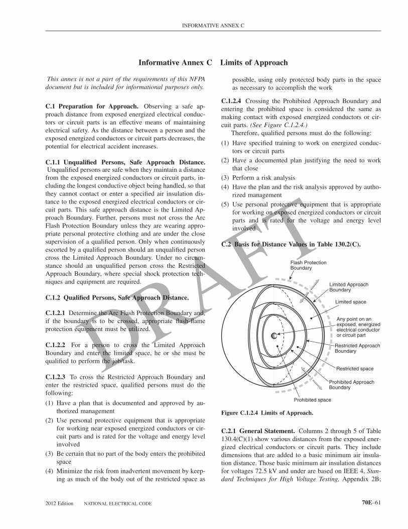
INFORMATIVE ANNEX C
Informative Annex C Limits of Approach
This annex is not a part of the requirements of this NFPAdocument but is included for informational purposes only.
C.1 Preparation for Approach. Observing a safe ap-proach distance from exposed energized electrical conduc-tors or circuit parts is an effective means of maintainingelectrical safety. As the distance between a person and theexposed energized conductors or circuit parts decreases, thepotential for electrical accident increases.
C.1.1 Unqualified Persons, Safe Approach Distance.Unqualified persons are safe when they maintain a distancefrom the exposed energized conductors or circuit parts, in-cluding the longest conductive object being handled, so thatthey cannot contact or enter a specified air insulation dis-tance to the exposed energized electrical conductors or cir-cuit parts. This safe approach distance is the Limited Ap-proach Boundary. Further, persons must not cross the ArcFlash Protection Boundary unless they are wearing appro-priate personal protective clothing and are under the closesupervision of a qualified person. Only when continuouslyescorted by a qualified person should an unqualified personcross the Limited Approach Boundary. Under no circum-stance should an unqualified person cross the RestrictedApproach Boundary, where special shock protection tech-niques and equipment are required.
C.1.2 Qualified Persons, Safe Approach Distance.
C.1.2.1 Determine the Arc Flash Protection Boundary and,if the boundary is to be crossed, appropriate flash-flameprotection equipment must be utilized.
C.1.2.2 For a person to cross the Limited ApproachBoundary and enter the limited space, he or she must bequalified to perform the job/task.
C.1.2.3 To cross the Restricted Approach Boundary andenter the restricted space, qualified persons must do thefollowing:
(1) Have a plan that is documented and approved by au-thorized management
(2) Use personal protective equipment that is appropriatefor working near exposed energized conductors or cir-cuit parts and is rated for the voltage and energy levelinvolved
(3) Be certain that no part of the body enters the prohibitedspace
(4) Minimize the risk from inadvertent movement by keep-
ing as much of the body out of the restricted space as2012 Edition NATIONAL ELECTRICAL CODE
possible, using only protected body parts in the spaceas necessary to accomplish the work
C.1.2.4 Crossing the Prohibited Approach Boundary andentering the prohibited space is considered the same asmaking contact with exposed energized conductors or cir-cuit parts. (See Figure C.1.2.4.)
Therefore, qualified persons must do the following:
(1) Have specified training to work on energized conduc-tors or circuit parts
(2) Have a documented plan justifying the need to workthat close
(3) Perform a risk analysis
(4) Have the plan and the risk analysis approved by autho-rized management
(5) Use personal protective equipment that is appropriatefor working on exposed energized conductors or circuitparts and is rated for the voltage and energy levelinvolved
C.2 Basis for Distance Values in Table 130.2(C).
C.2.1 General Statement. Columns 2 through 5 of Table130.4(C)(1) show various distances from the exposed ener-gized electrical conductors or circuit parts. They includedimensions that are added to a basic minimum air insula-tion distance. Those basic minimum air insulation distancesfor voltages 72.5 kV and under are based on IEEE 4, Stan-
Restricted space
Limited ApproachBoundary
Prohibited ApproachBoundary
Any point on anexposed, energizedelectrical conductoror circuit part
Limited space
Flash ProtectionBoundary
Restricted ApproachBoundary
Prohibited space
Figure C.1.2.4 Limits of Approach.
dard Techniques for High Voltage Testing, Appendix 2B;
70E–61

(
(
Ctv
1
e
oi
m
op
Ci
(
(
p
(
(
(
ofa
INFORMATIVE ANNEX C
and voltages over 72.5 kV are based on IEEE 516, Guidefor Maintenance Methods on Energized Power Lines. Theminimum air insulation distances that are required to avoidflashover are as follows:
(1) ≤300 V: 1 mm (0 ft 0.03 in.)
(2) >300 V ≤750 V: 2 mm (0 ft 0.07 in.)
(3) >750 V ≤2 kV: 5 mm (0 ft 0.19 in.)
(4) >2 kV ≤15 kV: 39 mm (0 ft 1.5 in.)
(5) >15 kV ≤36 kV: 161 mm (0 ft 6.3 in.)
(6) >36 kV ≤48.3 kV: 254 mm (0 ft 10.0 in.)
(7) >48.3 kV ≤72.5 kV: 381 mm (1 ft 3.0 in.)
(8) >72.5 kV ≤121 kV: 640 mm (2 ft 1.2 in.)
(9) >138 kV ≤145 kV: 778 mm (2 ft 6.6 in.)
(10) >161 kV ≤169 kV: 915 mm (3 ft 0.0 in.)
(11) >230 kV ≤242 kV: 1.281 m (4 ft 2.4 in.)
(12) >345 kV ≤362 kV: 2.282 m (7 ft 5.8 in.)
(13) >500 kV ≤550 kV: 3.112 m (10 ft 2.5 in.)
(14) >765 kV ≤800 kV: 4.225 m (13 ft 10.3 in.)
C.2.1.1 Column 1. The voltage ranges have been selectedto group voltages that require similar approach distancesbased on the sum of the electrical withstand distance and aninadvertent movement factor. The value of the upper limitfor a range is the maximum voltage for highest nominalvoltage in the range, based on ANSI/IEEE C84.1, ElectricPower Systems and Equipment— Voltage Ratings (60 Hz).For single-phase systems, select the range that is equal tothe system’s maximum phase-to-ground voltage multipliedby 1.732.
C.2.1.2 Column 2. The distances in this column are basedon OSHA’s rule for unqualified persons to maintain a 3.05m (10 ft) clearance for all voltages up to 50 kV (voltage-to-ground), plus 102 mm (4.0 in.) for each 1 kV over 50kV.
C.2.1.3 Column 3. The distances are based on the follow-ing:
(1) ≤750 V: Use NEC Table 110.26(A)(1), Working
Spaces, Condition 2 for 151 V–600 V range. p70E–62
2) >750 V ≤145 kV: Use NEC Table 110.34(A), WorkingSpace, Condition 2.
3) >145 kV: Use OSHA’s 3.05 m (10 ft) rules as used inColumn 2.
.2.1.4 Column 4. The distances are based on adding tohe flashover dimensions shown above the following inad-ertent movement distance:
≤300 V: Avoid contact.Based on experience and precautions for household
20/240 V systems:>300 V ≤750 V: Add 304.8 mm (1 ft 0 in.) for inadvert-
nt movement.These values have been found to be adequate over years
f use in ANSI/IEEE C2, National Electrical Safety Code,n the approach distances for communication workers.
>72.5 kV: Add 304.8 mm (1 ft 0 in.) for inadvertentovement.
These values have been found to be adequate over yearsf use in the National Electrical Safety Code in the ap-roach distances for supply workers.
.2.1.5 Column 5. The distances are based on the follow-ng:
1) ≤300 V: Avoid contact.
2) >300 ≤750 V: Use NEC Table 230.51(C), Clearances.
Between open conductors and surfaces, 600 V not ex-osed to weather.
1) >750 V ≤2.0 kV: Select value that fits in with adjacentvalues.
2) >2 kV ≤72.5 kV: Use NEC Table 490.24, MinimumClearance of Live Parts, outdoor phase-to-ground val-ues.
3) >72.5 kV: Add 152.4 mm (0 ft 6 in.) for inadvertentmovement.
These values have been found to be adequate over yearsf use where there has been a hazard/risk analysis, eitherormal or informal, of a special work procedure that allowscloser approach than that permitted by the Restricted Ap-
roach Boundary distance.NATIONAL ELECTRICAL CODE 2012 Edition

INFORMATIVE ANNEX D
Informative Annex D Incident Energy and Flash Arc Boundary Calculation Methods[ROP-499]
This annex is not a part of the requirements of this NFPAdocument but is included for informational purposes only.
D.1 Introduction. Annex D summarizes calculationmethods available for calculating arc flash boundary andincident energy. It is important to investigate the limitationsof any methods to be used. The limitations of methodssummarized in Annex D are described in Table D.1.
D.2 Basic Equations for Calculating Arc Flash Protec-tion Boundary Distances. The short-circuit symmetricalampacity from a bolted 3-phase fault at the transformerterminals is calculated with the following formula:
[D.2(a)]I MVA V Zsc = × ÷ × × ÷ % Base 10 1 732 1006⎡⎣ ⎤⎦ [ ]{ } { }.
where Isc is in amperes, V is in volts, and %Z is based
Table D.1 Limitation of Calculation Methods
Section Source Limitations/Parameters
D.2, D.3, D.4 Ralph Leepaper
Calculates Arc Flash ProtectionBoundary for arc in open air;conservative over 600 V andbecomes more conservative asvoltage increases
D.5 Doughty/Nealpaper
Calculates incident energy for3-phase arc on systems rated600 V and below; applies toshort-circuit currents between16 kA and 50 kA
D.6 Ralph Leepaper
Calculates incident energy for3-phase arc in open air onsystems rated above 600 V;becomes more conservative asvoltage increases
D.7 IEEE Std.1584
Calculates incident energy andArc Flash Protection Boundaryfor:208 V to 15 kV; 3-phase; 50Hz to 60 Hz; 700 A to 106,000A short-circuit current; and13 mm to 152 mm conductorgaps
D.8 ANSI/IEEE C2NESC-Section410 Tables410-1 andTable 410-2
Calculates incident energy foropen air phase-to-ground arcs 1kV to 500 kV for live-linework
on the transformer MVA.
2012 Edition NATIONAL ELECTRICAL CODE
A typical value for the maximum power (in MW) in a3-phase arc can be calculated using the following formula:
[D.2(b)]P MVAbf= ×maximum bolted fault in ⎡⎣ ⎤⎦ 0 7072.
[D.2(c)]P V Isc= × × × ×−1 732 10 0 7076 2. .
The Flash Protection Boundary distance is calculated inaccordance with the following formulae:
[D.2(d)]D MVA tc bf= × ×2 65
12
.⎡⎣ ⎤⎦
[D.2(e)]D MVA tc = × ×53
12[ ]
where:Dc = distance in feet of person from arc source for a
just curable burn (i.e., skin temperature remainsless than 80°C)
MVAbf = bolted fault MVA at point involvedMVA = MVA rating of transformer. For transformers
with MVA ratings below 0.75 MVA, multiply thetransformer MVA rating by 1.25.
t = time of arc exposure in seconds
The clearing time for a current limiting fuse is approxi-mately 1⁄4 cycle or 0.004 second if the arcing fault current isin the fuse’s current limiting range. The clearing time of a 5kV and 15 kV circuit breaker is approximately 0.1 secondor 6 cycles if the instantaneous function is installed andoperating. This can be broken down as follows: actualbreaker time (approximately 2 cycles), plus relay operatingtime of approximately 1.74 cycles, plus an additional safetymargin of 2 cycles, giving a total time of approximately 6cycles. Additional time must be added if a time delay func-tion is installed and operating.
The formulas used in this explanation are from RalphLee,“The Other Electrical Hazard: Electrical Arc BlastBurns,” in IEEE Trans. Industrial Applications. Vol. 1A-18.No. 3, Page 246, May/June 1982. The calculations arebased on the worst-case arc impedance. See Table D.2.
D.3 Single Line Diagram of a Typical PetrochemicalComplex. The single line diagram (see Figure D.3) illus-trates the complexity of a distribution system in a typicalpetrochemical plant.
D.4 Sample Calculation. Many of the electrical charac-
teristics of the systems and equipment are provided in Table70E–63

b
DAbposwvb(vm
l
(
-degree
INFORMATIVE ANNEX D
D.2. The sample calculation is made on the 4160-volt bus4A or 4B. Table D.2 tabulates the results of calculating theFlash Protection Boundary for each part of the system. Forthis calculation, based on Table D.2, the following resultsare obtained:
(1) Calculation is made on a 4160-volt bus.
(2) Transformer MVA (and base MVA) = 10 MVA.
(3) Transformer impedance on 10 MVA base = 5.5 percent.
(4) Circuit breaker clearing time = 6 cycles.
Using Equation D.2(a), calculate the short-circuit cur-rent:
I MVA Vsc = × ÷ × × ÷ %Ζ
= × ÷
Base 10 1 732 100
10 10 1 73
6
6
⎡⎣ ⎤⎦ [ ]{ } { }⎡⎣ ⎤⎦
.
. 22 4160 100 5 5
25 000
× × ÷
=
[ ]{ } { }.
, amperes
Using Equation D.2(b), calculate the power in the arc:
P = × × × ×=
−1 732 4160 25 000 10 0 707
91
6 2. , .
MW
Using the Equation D.2(d), calculate the second-degreeburn distance:
Dc = × × × × ×
=
−2 65 1 732 25 000 4160 10 0 1
6 9 7 00
61
2
. . , .
. .
⎡⎣ ⎤⎦{ } or ft
Table D.2 Flash Burn Hazard at Various Levels in a Large P
(1) (2) (3)
Bus Nominal VoltageLevels
System(MVA)
Transformer(MVA)
SyTra
(
230 kV 9000
13.8 kV 750
Load side of all13.8 kV fuses
750
4.16 kV 10.0
4.16 kV 5.0
Line side of incoming600 V fuse
2.5
600 V bus 2.5
600 V bus 1.5
600 V bus 1.0
*Distance from an open arc to limit skin damage to a curable second
70E–64
Or, using Equation D.2(e), calculate the second-degreeurn distance using an alternative method:
Dc = × ×=
53 10 0 1
7 28
12.
.[ ]
ft
.5 Calculation of Incident Energy Exposure for anrc Flash Hazard Analysis. The following equations cane used to predict the incident energy produced by a three-hase arc on systems rated 600 volts and below. The resultsf these equations might not represent the worst case in allituations. It is essential that the equations be used onlyithin the limitations indicated in the definitions of theariables shown under the equations. The equations muste used only under qualified engineering supervision.Note: Experimental testing continues to be performed toalidate existing incident energy calculations and to deter-ine new formulas.)
The parameters required to make the calculations fol-ow:
1) The maximum “bolted fault” three-phase short-circuitcurrent available at the equipment and the minimumfault level at which the arc will self-sustain (Calcula-tions should be made using the maximum value, andthen at lowest fault level at which the arc is self-sustaining. For 480-volt systems, the industry accepted
emical Plant
(5) (6) (7)
rer
ShortCircuit
Symmetrical(A)
ClearingTime of
Fault(cycles)
Flash Protection BoundaryTypical Distance*
SI U.S.
23,000 6.0 15 m 49.2 ft
31,300 6.0 1.16 m 3.8 ft
31,300 1.0 184 mm 0.61 ft
25,000 6.0 2.96 m 9.7 ft
12,600 6.0 1.4 m 4.6 ft
44,000 60.0–120.0 7 m–11 m 23 ft–36 ft
44,000 0.25 268 mm 0.9 ft
26,000 6.0 1.6 m 5.4 ft
17,000 6.0 1.2 m 4 ft
skin burn [less than 80°C (176°F) on skin] in free air.
etroch
(4)
stem onsform% Z)
1.11
9.4
9.4
5.5
5.5
5.5
5.5
5.5
5.57
minimum level for a sustaining arcing fault is 38 per-
NATIONAL ELECTRICAL CODE 2012 Edition

INFORMATIVE ANNEX D
cent of the available “bolted fault” three-phase short-circuit current. The highest incident energy exposurecould occur at these lower levels where the overcurrentdevice could take seconds or minutes to open.)
(2) The total protective device clearing time (upstream ofthe prospective arc location) at the maximum short-circuit current, and at the minimum fault level at whichthe arc will sustain itself
(3) The distance of the worker from the prospective arc forthe task to be performed
Typical working distances used for incident energy cal-culations are as follows:
(1) Low voltage (600 V and below) MCC and panelboards— 455 mm (18 in.)
(2) Low voltage (600 V and below) switchgear — 610 mm
5MVA5.5%
5MVA5.5%
Bus 2A1TI Bus 2B
Bus 3B
Bus 5B
Bus 3A600 Volt
4.16kV2.5MVA5.5%
2.5MVA5.5%
2.5MVA5.5%
2.5MVA5.5%
600A
Bus 1A/113.8kV
Bus 5A600 Volt
2.5MVA5.5%
2.5MVA5.5%
Bus 6BBus 6A
600 Volt2.5MVA5.5%
2.5MVA5.5%
Bus 7BBus 7A
10MVA5.5%
10MVA5.5%
Bus 4BBus 4A
600 Volt
4.16kV
230kV/13.8kV
13
600A
13.8kV Bus 1A
230kV/13.8kV
16001 16002q q
B
Bus 1B/113.8kV
Figure D.3 Single Line Diagram of a Typical Petrochemical C
(24 in.)
2012 Edition NATIONAL ELECTRICAL CODE
(3) Medium voltage (above 600 V) switchgear — 910 mm(36 in.)
D.5.1 Arc in Open Air. The estimated incident energy foran arc in open air is
[D.5.1(a)]E D t F FMA A A= − +−5271 0 0016 0 0076 0 89381 9593 2. . . .⎡⎣ ⎤⎦
where:EMA = maximum open arc incident energy, cal/cm2
DA = distance from arc electrodes, in. (for distances18 in. and greater)
tA = arc duration, secondsF = short-circuit current, kA (for the range of 16
kA to 50 kA)
us 1B
Public utility9,000 MVA faultavailable
.5MVA5.5%
1 MVA5.57%
600V Bus 11B
x.
.8kV B
1
600V us 10B
omple
70E–65

erc
(
(
(
(
w
F
V
t
D
DaiFagmdabi
INFORMATIVE ANNEX D
•
Sample Calculation: Using Equation D.5.1(a), calculatethe maximum open arc incident energy, cal/cm2, where DA
= 18 in., tA = 0.2 second, and F = 20 kA. [ROP-501][D.5.1(b)]
E D t F FMA A A= − +
= × .0035
5271 0 0016 0 0076 0 8938
5271
1 9593 2 − ⎡⎣ ⎤⎦. . . .
×× 0.2 0.0016 × 400 − 0.0076 × 20 + 0.8938= ×
=
[ ][ ]3 69 1 381
21 33
. .
. J/cm22 5 098. cal/cm2( )
D.5.2 Arc in a Cubic Box. The estimated incident energyfor an arc in a cubic box (20 in. on each side, open on oneend) is given in the following equation. This equation isapplicable to arc flashes emanating from within switchgear,motor control centers, or other electrical equipment enclo-sures.
[D.5.2(a)]E D t F FMB B A= − +−1038 7 0 0093 0 3453 5 96751 4738 2. . . .. ⎡⎣ ⎤⎦
where:EMB = maximum 20 in. cubic box incident energy,
cal/cm2
DB = distance from arc electrodes, inches (fordistances 18 in. and greater)
tA = arc duration, secondsF = short circuit current, kA (for the range of 16
kA to 50 kA)
Sample Calculation: Using Equation D.5.2(a), calculatethe maximum 20 in. cubic box incident energy, cal/cm2,using the following:
(1) DB = 18 in.
(2) tA = 0.2 sec
(3) F = 20 kA
[D.5.2(b)]E D t F FMB B A= − +
= 1038 × 0.01
1038 7 0 0093 0 3453 5 96751 4738 2. . . ..− ⎡⎣ ⎤⎦441× 0.2 0.0093 × 400 − 0.3453 × 20 + 5.9675
= ×
=
[ ][ ]2 928 2 7815
34 1
. .
. J//cm cal/cm2 28 144.( )
D.5.3 Reference. The equations for this section were de-rived in the IEEE paper by R. L. Doughty, T. E. Neal, andH. L. Floyd, II, “Predicting Incident Energy to Better Man-age the Electric Arc Hazard on 600 V Power DistributionSystems,” Record of Conference Papers IEEE IAS 45thAnnual Petroleum and Chemical Industry Conference, Sep-tember 28–30, 1998.[ROP-502]
D.6 Calculation of Incident Energy Exposure GreaterThan 600 V for an Arc Flash Hazard Analysis. The
following equation can be used to predict the incident en- s70E–66
rgy produced by a three-phase arc in open air on systemsated above 600 V. The parameters required to make thealculations are as follows:
1) The maximum “bolted fault” three-phase short-circuitcurrent available at the equipment
2) The total protective device clearing time (upstream ofthe prospective arc location) at the maximum short-circuit current. If the total protective device clearingtime is longer than 2 seconds, consider how long aperson is likely to remain in the location of the arcflash. It is likely that a person exposed to an arc flashwill move away quickly if it is physically possible andtwo seconds is a reasonable maximum time for calcu-lations. A person in a bucket truck or a person who hascrawled into equipment will need more time to moveaway. Sound engineering judgment must be used inapplying the 2 second maximum clearing time, sincethere may be circumstances where an employee’segress is inhibited. [ROP-503]
3) The distance from the arc source
4) Rated phase-to-phase voltage of the system:
EF V tD
A= × × ×7932
here:
E = incident energy, cal/cm2
= bolted fault short-circuit current, kA
= system phase-to-phase voltage, kV
A
= arc duration, seconds
= distance from the arc source, inches
.7 Basic Equations for Calculating Incident Energynd Arc Flash Boundary.[ROP-506] This section detailsnformation available for estimating incident energy andlash Protection Boundaries based on statistical analysisnd curve fitting of available test data. An IEEE workingroup produced the data from tests it performed to produceodels of incident energy. Based on the selection of stan-
ard personal protective equipment (PPE) levels (1.2, 8, 25,nd 40 cal/cm2), it is estimated that the PPE arc rating wille equal to or greater than actual measured test values ofncident energy in 95% of the cases. [ROP-506]
Informational Note: When incident energy exceeds 40cal/cm2 at the working distance, greater emphasis than nor-mal should be placed on de-energizing before working onor near the exposed electrical conductors or circuit parts.
The complete data, including a spreadsheet calculator to
olve the equations, can be found in the IEEE 1584, GuideNATIONAL ELECTRICAL CODE 2012 Edition
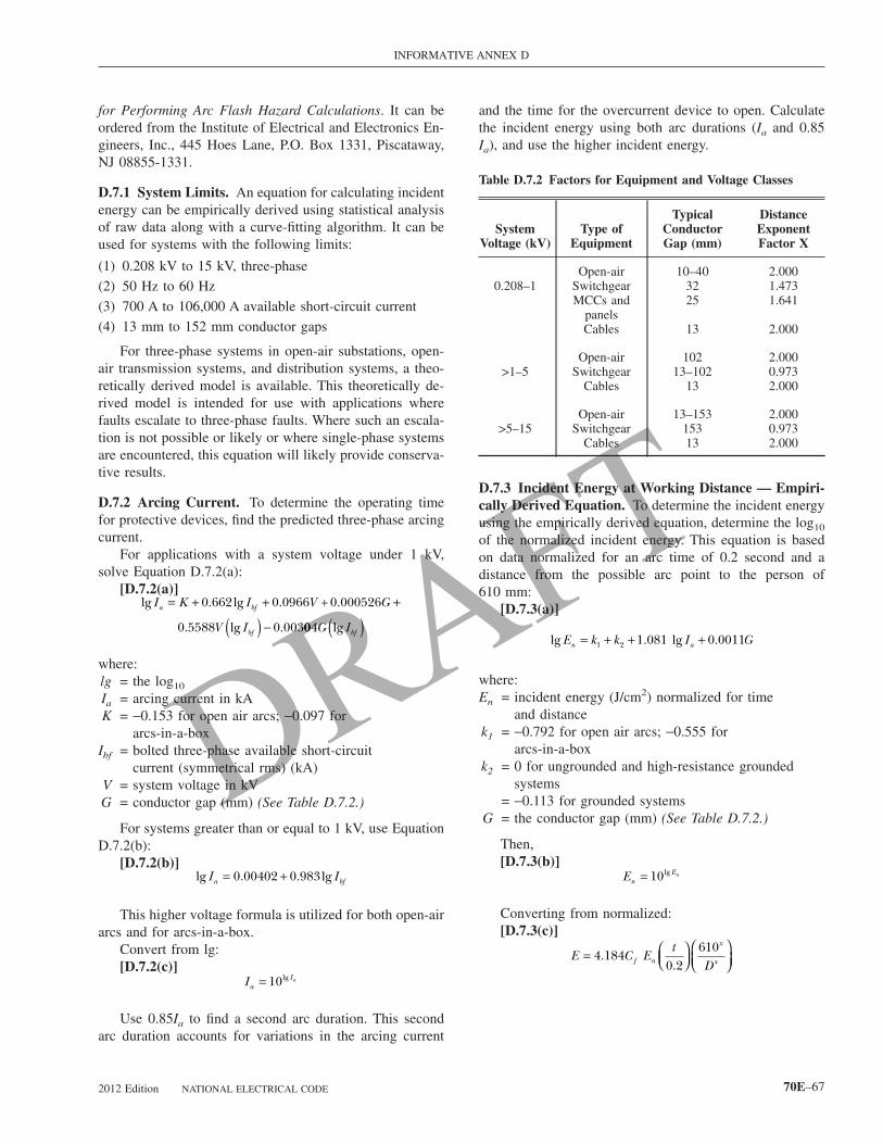
INFORMATIVE ANNEX D
for Performing Arc Flash Hazard Calculations. It can beordered from the Institute of Electrical and Electronics En-gineers, Inc., 445 Hoes Lane, P.O. Box 1331, Piscataway,NJ 08855-1331.
D.7.1 System Limits. An equation for calculating incidentenergy can be empirically derived using statistical analysisof raw data along with a curve-fitting algorithm. It can beused for systems with the following limits:
(1) 0.208 kV to 15 kV, three-phase
(2) 50 Hz to 60 Hz
(3) 700 A to 106,000 A available short-circuit current
(4) 13 mm to 152 mm conductor gaps
For three-phase systems in open-air substations, open-air transmission systems, and distribution systems, a theo-retically derived model is available. This theoretically de-rived model is intended for use with applications wherefaults escalate to three-phase faults. Where such an escala-tion is not possible or likely or where single-phase systemsare encountered, this equation will likely provide conserva-tive results.
D.7.2 Arcing Current. To determine the operating timefor protective devices, find the predicted three-phase arcingcurrent.
For applications with a system voltage under 1 kV,solve Equation D.7.2(a):
[D.7.2(a)]lg . lg . .
. lg .
I K I V G
V I
a bf
bf
= + + +
−
0 662 0 0966 0 000526
0 5588 0 003
+
( ) 004G Ibflg( )where:lg = the log10
Ia = arcing current in kAK = −0.153 for open air arcs; −0.097 for
arcs-in-a-boxIbf = bolted three-phase available short-circuit
current (symmetrical rms) (kA)V = system voltage in kVG = conductor gap (mm) (See Table D.7.2.)
For systems greater than or equal to 1 kV, use EquationD.7.2(b):
[D.7.2(b)]lg . . lgI Ia bf= +0 00402 0 983
This higher voltage formula is utilized for both open-airarcs and for arcs-in-a-box.
Convert from lg:[D.7.2(c)]
IaIa= 10lg
Use 0.85Ia to find a second arc duration. This second
arc duration accounts for variations in the arcing current2012 Edition NATIONAL ELECTRICAL CODE
and the time for the overcurrent device to open. Calculatethe incident energy using both arc durations (Ia and 0.85Ia), and use the higher incident energy.
D.7.3 Incident Energy at Working Distance — Empiri-cally Derived Equation. To determine the incident energyusing the empirically derived equation, determine the log10
of the normalized incident energy. This equation is basedon data normalized for an arc time of 0.2 second and adistance from the possible arc point to the person of610 mm:
[D.7.3(a)]
lg . lg .E I Gn a= + + +k k1 2 1 081 0 0011
where:En = incident energy (J/cm2) normalized for time
and distancek1 = −0.792 for open air arcs; −0.555 for
arcs-in-a-boxk2 = 0 for ungrounded and high-resistance grounded
systems= −0.113 for grounded systems
G = the conductor gap (mm) (See Table D.7.2.)
Then,[D.7.3(b)]
EnEn= 10lg
Converting from normalized:[D.7.3(c)]
E C Et
Df n
x
x= 4 1840 2
610.
. ⎛
⎝⎜⎞⎠⎟
⎛⎝⎜
⎞⎠⎟
Table D.7.2 Factors for Equipment and Voltage Classes
SystemVoltage (kV)
Type ofEquipment
TypicalConductorGap (mm)
DistanceExponentFactor X
Open-air 10–40 2.0000.208–1 Switchgear 32 1.473
MCCs andpanels
25 1.641
Cables 13 2.000
Open-air 102 2.000>1–5 Switchgear 13–102 0.973
Cables 13 2.000
Open-air 13–153 2.000>5–15 Switchgear 153 0.973
Cables 13 2.000
70E–67

w
I
b
DPlsc
wD
DtutuT
m
(
INFORMATIVE ANNEX D
where:E = incident energy in J/cm2
Cf = calculation factor= 1.0 for voltages above 1 kV= 1.5 for voltages at or below 1 kV
En = incident energy normalizedt = arcing time (seconds)
D = distance (mm) from the arc to the person(working distance). See Table D.7.3 for typicalworking distances.
X = the distance exponent from Table D.7.2
If the arcing time, t, in equation D.7.3(c), is longer thantwo seconds, consider how long a person is likely to remainin the location of the arc flash. It is likely that a personexposed to an arc flash will move away quickly if it isphysically possible and two seconds is a reasonable maxi-mum time for calculations. Sound engineering judgmentshould be used in applying the 2 second maximum clearingtime, because there may be circumstances where an em-ployee’s egress is inhibited. For example, a person in abucket truck or a person who has crawled into equipmentwill need more time to move away. [ROP-508]
D.7.4 Incident Energy at WorkingDistance—Theoretical Equation. The theoretically de-rived equation can be applied in cases where the voltage isover 15 kV or the gap is outside the range:
[D.7.4]
E VIt
Dbf= ×2 142 1062. ⎛
⎝⎜⎞⎠⎟
Table D.7.3 Typical Working Distances
Classes of EquipmentTypical Working Distance*
(mm)
15kV switchgear 910
5kV switchgear 910
Low-voltage switchgear 610
Low-voltage MCCs andpanelboards
455
Cable 455
Other To be determined in field
* Typical working distance is the sum of the distance between theworker and the front of the equipment and the distance from the frontof the equipment to the potential arc source inside the equipment.
c
70E–68
here:E = incident energy (J/cm2)V = system voltage (kV)t = arcing time (seconds)
D = distance (mm) from the arc to the person(working distance)
bf = available three-phase bolted-fault current
For voltages over 15 kV, arcing-fault current andolted-fault current are considered equal.
.7.5 Arc Flash Protection Boundary. The Arc Flashrotection Boundary is the distance at which a person is
ikely to receive a second-degree burn. The onset of aecond-degree burn is assumed to be when the skin re-eives 5.0 J/cm2 of incident energy.
For the empirically derived equation,[D.7.5(a)]
D C Et
EB f n
x
B
x
= 4 1840 2
6101
..
⎛⎝⎜
⎞⎠⎟
⎛⎝⎜
⎞⎠⎟
⎡
⎣⎢⎢
⎤
⎦⎥⎥
For the theoretically derived equation,[D.7.5(b)]
D VIt
EB bfB
= ×2 142 106.⎛⎝⎜
⎞⎠⎟
here:
B = the distance (mm) of the Arc Flash ProtectionBoundary from the arcing point
Cf = a calculation factor= 1.0 for voltages above 1 kV= 1.5 for voltages at or below 1 kV
En = incident energy normalizedEB = incident energy in J/cm2 at the distance of the
Arc Flash Protection Boundaryt = time (seconds)
X = the distance exponent from Table D.7.2Ibf = bolted 3-phase available short-circuit currentV = system voltage in kV
Informational Note: These equations could be used to de-termine whether selected PPE is adequate to prevent ther-mal injury at a specified distance in event of an arc flash.
.7.6 Current-Limiting Fuses. The formulas in this sec-ion were developed for calculating arc-flash energies forse with current-limiting Class L and Class RK1 fuses. Theesting was done at 600 volts and at a distance of 455 mm,sing commercially available fuses from one manufacturer.he following variables are noted:
Ibf = available three-phase bolted-fault current (sym-etrical rms) (kA)
E = incident energy (J/cm2)
A) Class L Fuses 1,601 A–2,000 A. Where Ibf <22.6 kA,
alculate the arcing current using Equation D.7.2(a), andNATIONAL ELECTRICAL CODE 2012 Edition

INFORMATIVE ANNEX D
use time-current curves to determine the incident energyusing Equations D.7.3(a), D.7.3(b), and D.7.3(c).
Where 22.6 kA ≤Ibf ≤65.9 kA,[D.7.6(a)]
E Ibf= − +4 184 0 1284 32 262. . .( )Where 65.9 kA < Ibf ≤106 kA,[D.7.6(b)]
E Ibf= − +4 184 0 5177 57 917. . .( )Where Ibf >106 kA, contact manufacturer.
(B) Class L Fuses 1,201 A–1,600 A. Where Ibf <15.7 kA,calculate the arcing current using Equation D.7.2(a), anduse time-current curves to determine the incident energyusing Equations D.7.3(a), D.7.3(b), and D.7.3(c).
Where 15.7 kA ≤Ibf ≤31.8 kA,[D.7.6(c)]
E Ibf= − +4 184 0 1863 27 926. . .( )Where 31.8 kA <Ibf <44.1 kA,[D.7.6(d)]
E Ibf= − +4 184 1 5504 71 303. . .( )Where 44.1 kA ≤Ibf ≤65.9 kA,[D.7.6(e)]
E = 12 3 2 942 2. .J/cm cal/cm( )
Where 65.9 kA <Ibf ≤106 kA,[D.7.6(f)]
E Ibf= − +4 184 0 0631 7 0878. . .( )Where Ibf >106 kA, contact manufacturer.
(C) Class L Fuses 801 A–1,200 A. Where Ibf <15.7 kA,calculate the arcing current per Equation D.7.2(a), and usetime-current curves to determine the incident energy perEquations D.7.3(a), D.7.3(b), and D.7.3(c).
Where 15.7 kA ≤Ibf ≤22.6 kA,[D.7.6(g)]
E Ibf= − +4 184 0 1928 14 226. . .( )Where 22.6 kA <Ibf ≤44.1 kA,[D.7.6(h)]
E I Ibf bf= − +4 184 0 0143 1 3919 34 0452. . . .( )Where 44.1 kA <Ibf ≤106 kA,[D.7.6(i)]
E = 1 63.
Where Ibf >106 kA, contact manufacturer.
(D) Class L Fuses 601 A–800 A. Where Ibf <15.7 kA,
calculate the arcing current per Equation D.7.2(a), and use2012 Edition NATIONAL ELECTRICAL CODE
time-current curves to determine the incident energy usingEquations D.7.3(a), D.7.3(b), and D.7.3(c).
Where 15.7 kA ≤Ibf ≤44.1 kA,[D.7.6(j)]
E Ibf= − +4 184 0 0601 2 8992. . .( )Where 44.1 kA < Ibf ≤106 kA,[D.7.6(k)]
E = 1 046.
Where Ibf > 106 kA, contact manufacturer.
(E) Class RK1 Fuses 401 A–600 A. Where Ibf <8.5 kA,calculate the arcing current using Equation D.7.2(a), anduse time-current curves to determine the incident energyusing Equations D.7.3(a), D.7.3(b), and D.7.3(c).
Where 8.5 kA ≤Ibf ≤14 kA,[D.7.6(l)]
E Ibf= − +4 184 3 0545 43 364. . .( )Where 14 kA < Ibf ≤15.7 kA,[D.7.6(m)]
E = 2 510.
Where 15.7 kA < Ibf ≤22.6 kA,[D.7.6(n)]
E Ibf= − +4 184 0 0507 1 3964. . .( )Where 22.6 kA < Ibf ≤106 kA,[D.7.6(o)]
E = 1 046.
Where Ibf >106 kA, contact manufacturer.
(F) Class RK1 Fuses 201 A–400 A. Where Ibf <3.16 kA,calculate the arcing current using Equation D.7.2(a), anduse time-current curves to determine the incident energyusing Equations D.7.3(a), D.7.3(b), and D.7.3(c).
Where 3.16 kA ≤Ibf ≤5.04 kA,[D.7.6(p)]
E Ibf= − +4 184 19 053 96 808. . .( )Where 5.04 kA < Ibf≤ 22.6 kA,[D.7.6(q)]
E Ibf= − +4 184 0 0302 0 9321. . .( )Where 22.6 kA <Ibf≤ 106 kA,[D.7.6(r)]
E = 1 046.
Where Ibf >106 kA, contact manufacturer.
(G) Class RK1 Fuses 101 A–200 A. Where Ibf <1.16 kA,
calculate the arcing current using Equation D.7.2(a), and70E–69

DTctwca
cae
it
wI
INFORMATIVE ANNEX D
use time-current curves to determine the incident energyusing Equations D.7.3(a), D.7.3(b), and D.7.3(c).
Where 1.16 kA ≤Ibf ≤1.6 kA,[D.7.6(s)]
E Ibf= − +4 184 18 409 36 355. . .( )Where 1.6 kA < Ibf ≤3.16 kA,[D.7.6(t)]
E Ibf= − +4 184 4 2628 13 721. . .( )Where 3.16 kA <Ibf ≤106 kA,[D.7.6(u)]
E = 1 046.
Where Ibf > 106 kA, contact manufacturer.
(H) Class RK1 Fuses 1 A–100 A. Where Ibf <0.65 kA,calculate the arcing current per Equation D.7.2(a), and usetime-current curves to determine the incident energy usingEquations D.7.3(a), D.7.3(b), and D.7.3(c).
Where 0.65 kA ≤Ibf ≤1.16 kA,[D.7.6(v)]
E Ibf= − +4 184 11 176 13 565. . .( )Where 1.16 kA < Ibf ≤1.4 kA,[D.7.6(w)]
E Ibf= − +4 184 1 4583 2 2917. . .( )Where 1.4 kA < Ibf ≤106 kA,[D.7.6(x)]
Table D.7.7 Incident Energy and Arc Flash Protection Bound
480
Rating (A) Breaker TypeTrip-Unit
TypeIncident Ene
(J/cm2)a
100–400 MCCB TM or M 0.189 Ibf + 0.
600–1,200 MCCB TM or M 0.223 Ibf + 1.
600–1,200 MCCB E, LI 0.377 Ibf + 1.
1,600–6,000 MCCB or ICCB TM or E, LI 0.448 Ibf + 3.
800–6,300 LVPCB E, LI 0.636 Ibf + 3.
800–6,300 LVPCB E, LSb 4.560 Ibf + 27
MCCB: Molded-case circuit breaker.ICCB: Insulated-case circuit breaker.LVPC: Low-voltage power circuit breaker.TM: Thermal-magnetic trip units.M: Magnetic (instantaneous only) trip units.E: Electronic trip units have three characteristics that may be used sea Ibf is in kA; working distance is 455 mm (18 in.).b
Short-time delay is assumed to be set at maximum.70E–70
E = 1 046.
Where Ibf > 106 kA, contact manufacturer.
.7.7 Low-Voltage Circuit Breakers. The equations inable D.7.7 can be used for systems with low-voltage cir-uit breakers. The results of the equations will determinehe incident energy and Arc Flash Protection Boundaryhen Ibf is within the range as described. Time-current
urves for the circuit breaker are not necessary within theppropriate range.
When the bolted-fault current is below the range indi-ated, calculate the arcing current per Equation D.7.2(a),nd use time-current curves to determine the incident en-rgy using Equations D.7.3(a), D.7.3(b), and D.7.3(c).
The range of available three-phase bolted-fault currentss from 700 A to 106,000 A. Each equation is applicable forhe range
I I Ibf1 2< <
here:
2 = the interrupting rating of the CB at the voltageof interest.
Circuit Breaker Type and Rating
Lower 575–600 V
Flash Boundary(mm)a
Incident Energy(J/cm2)a
Flash Boundary(mm)a
9.16 Ibf + 194 0.271 Ibf + 0.180 11.8 Ibf + 196
8.45 Ibf + 364 0.335 Ibf + 0.380 11.4 Ibf + 369
12.50 Ibf + 428 0.468 Ibf + 4.600 14.3 Ibf + 568
11.10 Ibf + 696 0.686 Ibf + 0.165 16.7 Ibf + 606
14.50 Ibf + 786 0.958 Ibf + 0.292 19.1 Ibf + 864
47.20 Ibf + 2660 6.860 Ibf + 2.170 62.4 Ibf + 2930
y or in combination: L: Long-time, S: Short-time, I: Instantaneous.
ary by
V and
rgy
548
590
360
000
670
.230
paratel
NATIONAL ELECTRICAL CODE 2012 Edition

INFORMATIVE ANNEX D
•
I1 = the minimum available three-phase, bolted,short-circuit current at which this method canbe applied. I1 is the lowest availablethree-phase, bolted, short-circuit current levelthat causes enough arcing current forinstantaneous tripping to occur or for circuitbreakers with no instantaneous trip, thatcauses short-time tripping to occur.
To find I1, the instantaneous trip (It) of the circuitbreaker must be found. This can be determined from thetime-current curve, or it can be assumed to be 10 times therating of the circuit breaker for circuit breakers rated above100 amperes. For circuit breakers rated 100 amperes andbelow, a value of It = 1,300 A can be used. When short-timedelay is utilized, It is the short-time pick-up current.
The corresponding bolted-fault current, Ibf, is found bysolving the equation for arc current for box configurationsby substituting It for arcing current. The 1.3 factor in Equa-tion D.7.7(b) adjusts current to the top of the tripping band.
[D.7.7(a)]lg
1 3 0 084 0 096
0 559
. . . lg
. lg
I V I
V I
t bf
bf
( ) ( )( )
= + + 0.586 +
At 600 V,[D.7.7(b)]
lg . . .I It1 0 0281 1 091 1 3= + g ( )
At 480 V and lower,[D.7.7(c)]
lg . . .I It1 0 0407 1 17 1 3= + lg ( )
[D.7.7(d)]I Ibf
I= =1 10 1lg
D.7.8 References. The complete data, including a spread-sheet calculator to solve the equations, may be found inIEEE 1584, Guide for Performing Arc Flash Hazard Cal-culations. IEEE publications are available from the Instituteof Electrical and Electronics Engineers, 445 Hoes Lane,P.O. Box 1331, Piscataway, NJ 08855-1331, USA(http://standards.ieee.org/).[ROP-511] [ROP-515]
2012 Edition NATIONAL ELECTRICAL CODE
D.8 DC Incident Energy Calculations. [ROP-517a]
D.8.1 DC Arc Flash Calculations.
D.8.1.1 Maximum power method. The following methodof estimating DC arc flash incident energy was presented atthe 2007 IEEE Electrical Safety Workshop (see reference 2below). This method is based on the concept that the maxi-mum power possible in a DC arc will occur when the arc-ing voltage is one half of the system voltage. Testing com-pleted for Bruce Power (reference 3 below) has shown thatthis calculation is conservatively high in estimating the arcflash value. This method applies to DC systems rated up to1000 VDC.
I IIE V I T D
arc bf
m sys arc arc
= ∗= ∗ ∗ ∗
0 50 01 2..
where:Vsys = the system voltage, in volts
Ibf = the system bolted fault current, in amperesIarc = the arcing current, in amperesTarc = the arcing time in seconds
D = the working distance, in centimetersIEm = the estimated DC arc flash incident energy at
the maximum power point, in cal/cm2
For exposures where the arc is in a box or enclosure, itwould be prudent to use a 3× multiplying factor for theresulting incident energy value.
D.8.1.2 Detailed Arcing Current and Energy Calcula-tions Method. A thorough theoretical review of DC arcingcurrent and energy was presented at the 2009 IEEE PCICConference. Readers are recommended to refer to that pa-per (reference 1 below) for those detailed calculations.
References:1. “DC arc models and incident energy calculations”,
Ammerman, R.F.; Gammon, T.; Sen, P.K.; Nelson, J.P.; Pe-troleum and Chemical Industry Conference, 2009, Recordof Conference Papers,14-16 Sept. 2009
2. “Arc Flash Calculations for Exposures to DC Sys-tems”, Doan, D.R., IEEE IAS Electrical Safety Workshop,2007, Record of Conference Papers, March 2007.
3. DC Arc Hazard Assessment Phase II Copyright Ma-terial Kinectrics Inc. Report No. K-012623-RA-0002-R00
70E–71