article 7: requirements for sewer construction · technical guidance manual 8-1-15 article 7....
TRANSCRIPT
Technical Guidance Manual 8-1-15
Article 7. Requirements for Sewer Construction Page 7-1
ARTICLE 7: REQUIREMENTS FOR SEWER CONSTRUCTION
Introduction For the protection of existing and future infrastructure, and in the interest of public health, all qualified sewer construction in Cook County is subject to regulation requiring formal approvals and permitting. Regulating sewer projects promotes minimum design and construction standards, provides a data repository of underground sewer infrastructure, and minimizes the risk to existing public and private infrastructure by requiring research, preparation, and coordination prior to a contractor beginning work.
GENERAL SEWER CONSTRUCTION REQUIREMENTS (§700)
Approximately 125 agencies (municipalities, sanitary districts, townships, and one utility
company) are tributary to the District’s collection system of interceptor sewers. These agencies
are relieved of the responsibility to own and operate a sewage treatment plant and benefit from
the economy of scale of large, regional sewage treatment plants. Older municipalities are built
upon a combined sewer system that conveys domestic sewage, industrial wastes, and
stormwater runoff to the District collection system. Municipalities constructed after 1945 are
generally on a separate sewer system where one pipe conveys domestic sewage and industrial
wastes with a separate pipe for the collection of stormwater runoff. The District maintains a
Combined Sewer Atlas to show what areas it considers to be on a combined sewer system and
what areas considered to be on a separate sewer system.
The District has the right to annex property within Cook County into the District Corporate limits.
This is done by an Act of the State Legislature. The District also has the right to enter into Sewer
Service Agreements with municipalities that are within Cook County and the District’s corporate
limits and also lie in an adjoining county such as Lake, DuPage, or Will Counties. Areas that are
annexed after July 9, 1998 must pay a Connection Impact Fee to the District for the area to be
served.
The District follows the design standards for public sewer systems as regulated by Title 35 of the
State of Illinois Administrative Code, Subtitle C, Part 370. While the District does not regulate
plumbing of buildings it may ask for plumbing plans to determine where waste flows are
originating from and how they are routed through the building.
Note: All bold terms contained in this document are defined terms in the WMO. Refer
to Appendix A of the WMO or the TGM for the definition of each bold term.
Technical Guidance Manual 8-1-15
Article 7. Requirements for Sewer Construction Page 7-2
QUALIFIED SEWER CONSTRUCTION (§701)
The District collects, treats, and disposes of sewage from approximately 95% of the land area of
Cook County. The suburbs of Chicago Heights, University Park, Park Forest, and the majority of
Homewood are tributary to the Thorn Creek Basin Sanitary District (TCBSD); construction and
replacement of sanitary or combined sewers in those communities should be coordinated
through TCBSD. Contact information is available on-line at the following website:
www.thorncreek.dst.il.us. The far northwest portion of Cook County (Barrington and the areas
immediately east of it) is also not in the corporate limits of the District and sanitary sewer
construction would be regulated by the appropriate local agency. Most of this area is currently on
septic and is not tributary to a sewage treatment plant. However, a Watershed Management
Permit is still needed for development in these areas of Cook County, even when they are not
located within the corporate boundaries of the MWRD or are not tributary to its treatment plants
(WMO §200.1) Service laterals for single-family homes and multi-family homes less than 3 units
within the corporate limits are not regulated by the WMO.
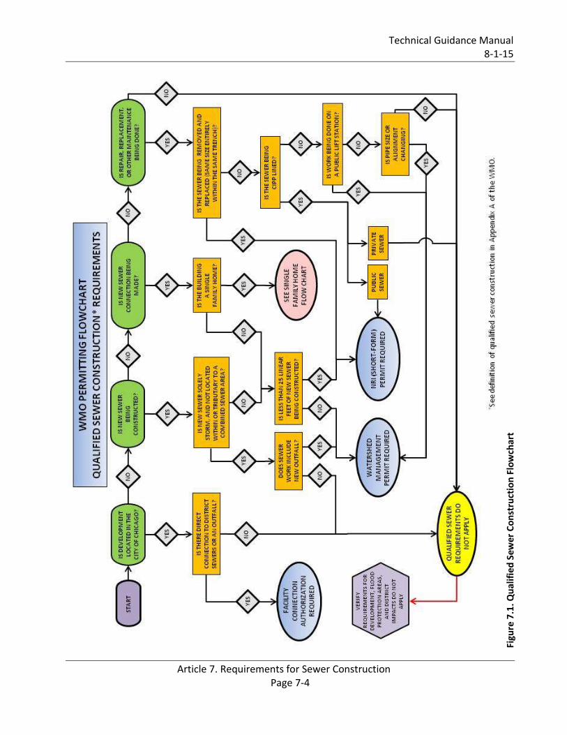
Construction or modification of storm sewers in a combined sewer area and construction of
storm sewers in a separate sewer area that discharge to a District facility are considered qualified
sewer construction and require a Watershed Management Permit. Refer to the qualified sewer
construction flowchart provided as Figure 7.1 for additional guidance. A permit from the District is
also required for development that impacts District property; a flowchart that navigates
applicants through District impacts is provided as Figure 7.2.
A Watershed Management Permit is required for cured-in-place pipe (CIPP) lining of public sewer
systems. CIPP lining of private sewer systems is considered non-qualified sewer construction.
Routine maintenance performed on an existing sewer system, public or private, such as grouting,
jetting, cleaning, and root cutting is not regulated by the WMO.
QUALIFIED SEWER CONSTRUCTION REQUIREMENTS (§702)
Qualified sewer construction is considered all public and private new sewers and new sewer
connections, exterior to the building envelope, including sewer repair and sewer replacement.
Any construction that is considered qualified sewer construction will require a Watershed
Management Permit. The following summarize the District’s requirements for qualified sewer
construction:
A. Single-Family Home
A service sewer, also referred to as a lateral, that serves a single-family home or two-unit
building to connect to the public sewer system does not require a Watershed Management
Technical Guidance Manual 8-1-15
Article 7. Requirements for Sewer Construction Page 7-3
Permit from the District. However, it does require a Watershed Management Permit if the
public sewer must be extended to serve that property.
B. Residential Subdivision
A residential subdivision of single-family homes or townhomes or multi-family residential
units requires a Watershed Management Permit.
C. Multi-Family Residential Sewer
A development that consists of a single building or structure that has more than two
individual dwelling units requires a Watershed Management Permit.
D. Non-Residential Service Sewer
Commercial, recreational, and industrial properties must apply for and receive a Watershed
Management Permit before they can be constructed and discharge into the public sewer
system. All such properties will require an inspection manhole that isolates the sewage being
discharged from the building before it leaves the private property. The inspection manhole
should be located at least 5 feet from the perimeter of the building and not be in a driveway
or traveled area. A manhole into which a force main discharges cannot be considered an
inspection manhole.
E. Public Lift Station/Force Main
The following items are required for a proposed lift station:
Schedule E – Lift Station (Schedule E is only required for publicly owned lift stations serving multiple service areas; an original PE Seal and signature is required on the Schedule E form).
Details of Construction;
Service Area Map;
Hydraulic design calculations;
Present and future population equivalents (PE);
Pump System Curves, Characteristic Curves, Operation Point;
Wet Well Capacity and Detention Time calculations (detention should be between 10 and 30 minutes);
Buoyancy Calculations for the lift station;
Lift stations are to be located a minimum of 25 feet horizontally from any water main; and
New lift stations shall not be located within the regulatory floodplain or have access openings and vents below the Flood Protection Elevation (FPE).
Technical Guidance Manual 8-1-15
Article 7. Requirements for Sewer Construction Page 7-4
Figu
re 7
.1. Q
ual
ifie
d S
ewer
Co
nst
ruct
ion
Flo
wch
art

Technical Guidance Manual 8-1-15
Article 7. Requirements for Sewer Construction Page 7-5
Figu
re 7
.2. D
istr
ict
Imp
acts
Flo
wch
art
Technical Guidance Manual 8-1-15
Article 7. Requirements for Sewer Construction Page 7-6
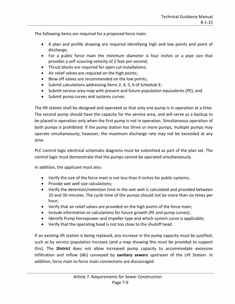
The following items are required for a proposed force main:
A plan and profile drawing are required identifying high and low points and point of discharge;
For a public force main the minimum diameter is four inches or a pipe size that provides a self scouring velocity of 2 feet per second;
Thrust blocks are required for open cut installations;
Air relief valves are required on the high points;
Blow off valves are recommended on the low points;
Submit calculations addressing items 2, 4, 5, 6 of Schedule E;
Submit service area map with present and future population equivalents (PE); and
Submit pump curves and systems curves. The lift station shall be designed and operated so that only one pump is in operation at a time.
The second pump should have the capacity for the service area, and will serve as a backup to
be placed in operation only when the first pump is not in operation. Simultaneous operation of
both pumps is prohibited. If the pump station has three or more pumps, multiple pumps may
operate simultaneously; however, the maximum discharge rate may not be exceeded at any
time.
PLC control logic electrical schematic diagrams must be submitted as part of the plan set. The
control logic must demonstrate that the pumps cannot be operated simultaneously.
In addition, the applicant must also:
Verify the size of the force main is not less than 4 inches for public systems;
Provide wet well size calculations;
Verify the detention/retention time in the wet well is calculated and provided between 10 and 30 minutes. The cycle time of the pumps should not be more than six times per hour;
Verify that air relief valves are provided on the high points of the force main;
Include information or calculations for future growth (PE and pump curves);
Identify Pump Horsepower and Impeller type and which system curve is applicable;
Verify that the operating head is not too close to the shutoff head. If an existing lift station is being replaced, any increase in the pump capacity must be justified,
such as by service population increase (and a map showing this must be provided to support
this). The District does not allow increased pump capacity to accommodate excessive
Infiltration and Inflow (I&I) conveyed by sanitary sewers upstream of the Lift Station. In
addition, force main to force main connections are discouraged.

Technical Guidance Manual 8-1-15
Article 7. Requirements for Sewer Construction Page 7-7
For private lift stations, the engineer must provide the force main profile and Special
Conditions will be attached to the permit. A private lift station serves a sole property even if
that property is publicly owned. A separate inspection manhole shall be provided upstream of
the wet well for any non-residential facilities tributary to the private lift station.
For stormwater lift stations, check downstream conditions that may limit or constrict flow
such as culverts under a roadway.
F. District Interceptor, TARP and other Direct Connections to District Facilities
Procure applicable District record drawings, design standards, and specifications relevant to the proposed connection.
Provide a map of the service area for the proposed sewer.
Provide a detail of the connection to the District facility including size, pipe material, details of District structure, and proposed structure.
Provide an auxiliary manhole upstream of the proposed connection.
Before construction commences, provide calculations prepared and sealed by a Structural Engineer licensed in the State of Illinois for excavation support systems that may be required.
Provide a bypass pumping plan, if required.
G. Outfall Connection
For proposed outfall connections, the following must be provided:
Provide a map of the service area for the proposed outfall.
Provide a natural or mechanical flow-through device (see Lake Michigan Outfall Water
Quality Structure Typical Detail).
Provide a headwall for the outfall, a precast flared end Section may be provided for
outfalls that are 15 inches or less in diameter such as IDOT Standard 542301. For larger
outfalls, a cast in place headwall must be provided – such as IDOT Standard 542101 –
or be part of the permanent dock wall.
Energy dissipation by the use of a level spreader or rip-rap placement must be provided
when discharging at a grade.
Details of the energy dissipation system must be provided.
Consider if a backflow prevention device is required when the receiving waterway is at
flood stage. Backflow preventers are required for stormwater detention systems in
separate sewer areas with flood control projects and also in combined sewer areas
where an open detention pond is proposed.
Provide WMO Schedule O (see §608 of the WMO for outfall requirements).
Technical Guidance Manual 8-1-15
Article 7. Requirements for Sewer Construction Page 7-8
Should the outfall pierce an existing dock wall, such as a driven sheet pile wall, a detail
of the wall penetration must be prepared and sealed by a Structural Engineer licensed
in the State of Illinois.
A Special Condition requiring the owner of the outfall to obtain a National Pollutant
Discharge Elimination System (NPDES) permit from the IEPA is attached to the permit.
H. Treatment and Pretreatment Facilities (such as Treatment Plants and Oxidation Ponds)
Provide technical data on the operation of the facilities including criteria and calculations, such as the following:
Process Flow Schematics.
Provide Schedule G (or IEPA Schedule J).
Provide a flow meter to measure water into the facility.
Provide a sampling chamber or inspection access where samples of the effluent can be taken.
Provide a surety bond for the maintenance and operation of the facility.
I. Septic Systems
The District does not regulate the design, construction, or maintenance of septic systems for
sewage disposal serving a home or building. When allowed, the local authority would be the
permitting agency for such an installation. In unincorporated Cook County, the County’s
Department of Public Health would regulate and permit such an installation. Septic systems
cannot discharge their effluent to a sewer tributary to the District’s interceptor sewer system.
When disconnection from a septic system and sanitary service connection is made, the existing
septic system must be abandoned by pumping out any residual sludge, completely filling the
abandoned septic tanks with granular material such as IDOT FA 2 or CA 6, and plugging the
ends with grout. Alternatively, the septic system could be completely removed. If the existing
tank is left in place, the bottom slab should be punctured to allow water to drain out, and the
ends plugged with grout. Connections and piping to the new sanitary sewer system must be
made upstream of the septic tank and must be watertight.
J. Sewer Construction in Floodplain
Provide watertight, bolt down covers on sanitary or combined sewer manholes that may be
inundated during a flood condition. This would be considered any area that is less than two
feet above the Base Flood Elevation, Flood Protection Elevation, or the detention system’s
High Water Level. The Flood Protection Elevation (FPE) is defined as the Base Flood Elevation
plus two feet of freeboard.

Technical Guidance Manual 8-1-15
Article 7. Requirements for Sewer Construction Page 7-9
FACILITY CONNECTION AUTHORIZATION (§703)
Within the City of Chicago, a Facility Connection Authorization (FCA) must be prepared for
connections made directly or indirectly to District facilities. The FCA is signed by an authorized
representative of the Department of Water Management. Projects that cross District property to
reach a waterway require an easement from the Law Department’s Real Estate Section. The
technical details would be the same as listed under subsection F. District Interceptor, Tarp and
other Direct Connections.
THE SEWER CONSTRUCTION PROCESS
Starting the Project
First, identify where the project is located and which public sewer the sewage will discharge to.
The municipality that owns the public sewer is the “permittee.” The property owner whose
building or facility is discharging the sewage is the “co-permittee.” There are situations where the
sewage discharges directly to a District interceptor sewer, generally known as a “Sole Permittee.”
There are locations where sewage and/or stormwater flow through more than one municipality’s
sewer before it reaches the District interceptor or the receiving stream. In such cases an
additional Page 7 and Page 8 are required indicating that the municipality is aware and agrees to
the project and certifies that their sewer system has adequate capacity. Information about existing
Sewerage System Permits that may be helpful can be obtained by forwarding an email to the
head of the Local Sewer System Section and requesting that a search of the permit data base for a
given location be conducted. If a large number of permits are involved, the applicant will be asked
to go the Stickney Field Office and review the permits to determine what is relevant to the project.
Identify if the project is in a combined sewer area or a separate sewer area. The District
maintains an atlas that defines the areas considered to have been developed on a combined
sewer system. Some older municipalities have done partial separation by building storm sewers
for roadway drainage, but those municipalities are still considered to be on a combined sewer
system.
Identify whether the project is residential, commercial, institutional, or industrial. The amount of
sewage to be generated from the project is calculated by using the chart in the State of Illinois
Recommended Standards for Sewage Works (Title 35 Part 370), Appendices A and B. It is
assumed that, on average, a person needs 100 gallons of water per day to bathe, cook, flush the
toilet and clean. It is also assumed that whatever water goes into a home or business comes out to
the public sewer.
Technical Guidance Manual 8-1-15
Article 7. Requirements for Sewer Construction Page 7-10
A Population Equivalent (PE) Calculation is required for any building connection or public sewer
extension. The PE calculation may be written on Schedule C (Page 7) or it can be attached as a
worksheet or shown on a drawing. Any time the PE calculation is not written on Schedule C (Page
7), a note should be written below the “PE** __” that indicates where the PE calculation is located
(i.e. “See Attachment or See Sheet C1.1”).
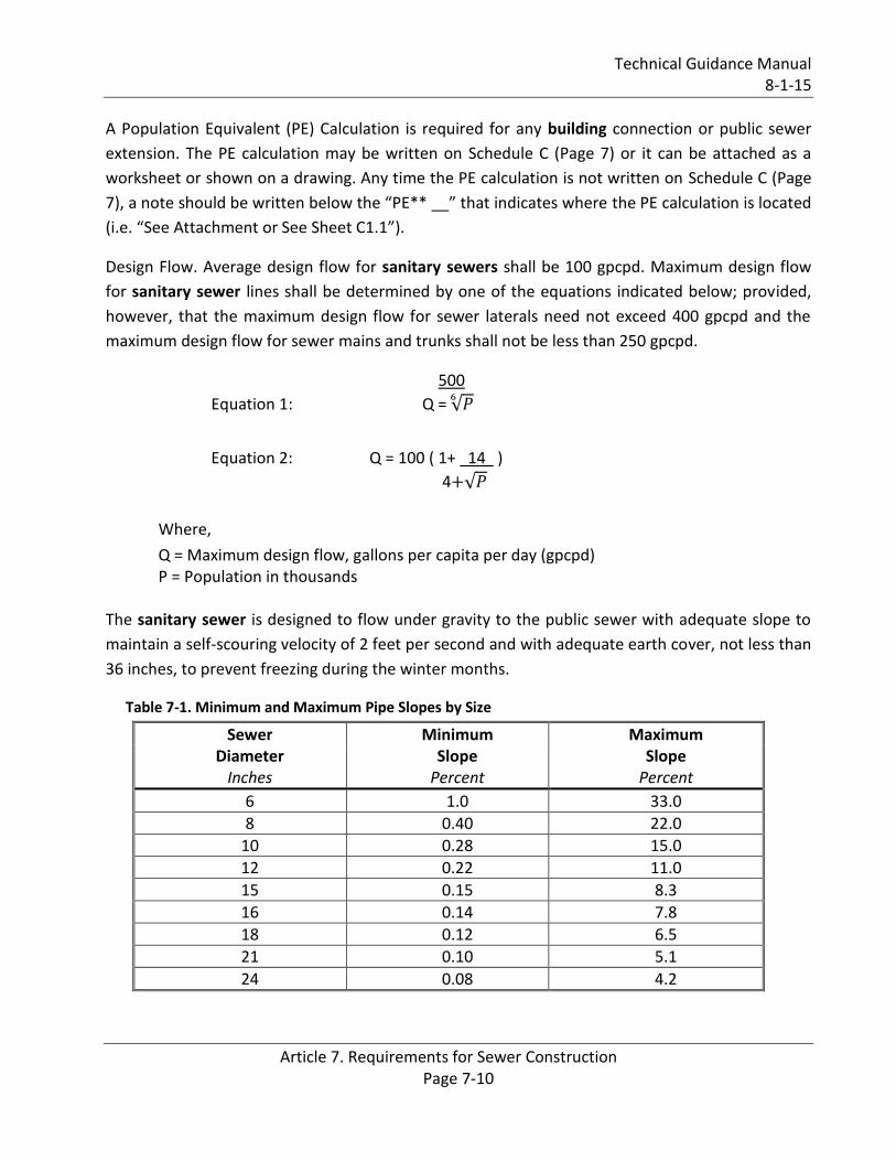
Design Flow. Average design flow for sanitary sewers shall be 100 gpcpd. Maximum design flow
for sanitary sewer lines shall be determined by one of the equations indicated below; provided,
however, that the maximum design flow for sewer laterals need not exceed 400 gpcpd and the
maximum design flow for sewer mains and trunks shall not be less than 250 gpcpd.
500
Equation 1: Q =
Equation 2: Q = 100 ( 1+ 14 )
4
Where,
Q = Maximum design flow, gallons per capita per day (gpcpd) P = Population in thousands
The sanitary sewer is designed to flow under gravity to the public sewer with adequate slope to
maintain a self-scouring velocity of 2 feet per second and with adequate earth cover, not less than
36 inches, to prevent freezing during the winter months.
Table 7-1. Minimum and Maximum Pipe Slopes by Size
Sewer Minimum Maximum Diameter Slope Slope
Inches Percent Percent
6 1.0 33.0
8 0.40 22.0
10 0.28 15.0
12 0.22 11.0
15 0.15 8.3
16 0.14 7.8
18 0.12 6.5
21 0.10 5.1
24 0.08 4.2

Technical Guidance Manual 8-1-15
Article 7. Requirements for Sewer Construction Page 7-11
Under special conditions, if detailed justifiable reasons are given, slopes slightly less than those
required for the 2 feet per second velocity when flowing full may be permitted. Such decreased
slopes will only be considered where the depth of flow will be 30% of the diameter or greater for
design average flow. Whenever such decreased slope are selected, the design engineer must
furnish with his report his computations of the depth of flow in such pipes at minimum, design
average, and design peak rates of flow. It must be recognized that decreased slopes may cause
additional sewer maintenance expense and special linings or materials should be considered for
corrosion protection. A letter from both the permittee and co-permittee acknowledging the
increased maintenance due to the decreased slope shall be provided to the District.
Design of the Sewer System
The sewer system is laid out in the most efficient alignment possible keeping in mind the presence
of other utilities such as potable water, natural gas, storm sewers, and electrical and
telecommunications cables. The design of the sewer system is laid out concurrently with the
grading plan to minimize any cut and fill earthwork the project may require and to ensure
adequate earth cover over the sanitary sewer. Occasionally there are situations where an outlying
building or public restroom for a park may be more efficiently served by constructing a grinder
pump and a small 2-inch diameter HDPE force main that outlets to the public sewer system than
constructing a gravity sewer.
Service Sewer
A service sewer, also known as a lateral, is defined as a sewer pipe receiving flow from a single
building, connecting to a sewer main, and constructed on private property, except for street
crossings. The maximum length of a service sewer shall not exceed 400 feet or 150 feet if access
to a sewer cleaning truck is not available. If the length is exceeded, an intermediate manhole shall
be built. Cleanouts may be used only for special conditions and shall not be substituted for
manholes nor installed at the end of laterals greater than 150 feet in length. Two consecutive
cleanouts in series are not allowed. When the service sewer connects to a sewer lateral of a size
not larger than the size of the service sewer, a manhole shall be built at the point of connection.
The minimum slope for a 6-inch diameter service line shall be one percent (1%).
Minimum design standards, and other requirements hereof, governing materials, joints,
infiltration, workmanship and maintenance for sewer mains and laterals shall also apply to service
sewers. Horizontal and vertical alignment of the service sewer shall be uniform and shall follow a
straight line alignment. Any change in sewer alignment will require a structure at the change.
There shall be no dips in the grade or fall of the line. Turns or bends required for the riser, if any,
necessary to connect to the sewer wye or tee, shall be made with standard bends.

Technical Guidance Manual 8-1-15
Article 7. Requirements for Sewer Construction Page 7-12
In those instances where the service sewer is partially constructed from the sewer lateral or main
to a point other than the building to be served, the pipe shall be tightly plugged using a
manufactured plug. The plug shall be pre-wired by the manufacturer so that it can be firmly
secured in place.
Combined Sewer Areas
In areas designated as combined sewer areas on the District Combined Sewer Atlas, the following
requirements shall apply:
a. Separation. Complete separation of storm and sanitary sewers shall be provided within
the property lines.
b. Down Spouts. All down-spouts or roof drains shall discharge onto the ground or be
connected to the storm or combined sewer. No down spouts or roof drains shall be
connected to the sanitary sewers.
c. Footing Drains. Footing drains shall be connected to sump pumps, and discharge shall be
made into storm sewers, combined sewers or drainage ditches. No footing drains or
drainage tile shall be connected to the sanitary sewer. After December 31, 1970 all new
construction shall conform to the requirements of this paragraph. No permit application
will be accepted, nor any permits issued after December 31, 1970 to any municipality or
local government unless said municipality or local government shall have adopted an
ordinance reflecting the requirements of this paragraph and a copy of said ordinance shall
have been filed with the District, or that the permittee and/or co-permittee shall agree to
comply with the requirements of this article.
d. Floor Drains. Floor drains in basements shall be connected to sump pumps and discharged
to the sanitary or combined sewers.
e. Sump Pumps. Sump pumps installed to receive and discharge groundwater or other
stormwater shall be connected to the storm or combined sewers or discharge into a
drainage ditch. Sump pumps installed to receive and discharge floor drain flow or other
sanitary sewage shall be connected to the sanitary or combined sewers. A sump pump
shall be used for one function only, either the discharge of stormwater or the discharge of
sanitary sewage.
f. Stormwater Detention. A backflow preventer is required for all detention basins tributary
to combined sewers. Required backflow preventers shall be inspected and exercised
annually by the property owner to ensure proper operation, and any necessary
maintenance shall be performed to ensure functionality. In the event of a sewer surcharge
into an open detention basin tributary to combined sewers, the permittee shall ensure
that clean up and wash out of sewage takes place within 48 hours of the storm event.
Technical Guidance Manual 8-1-15
Article 7. Requirements for Sewer Construction Page 7-13
Separate Sewer Areas
In areas served by separate sewer systems, the following requirements shall apply:
a. Down Spouts. All down-spouts or roof drains shall discharge onto the ground or be
connected to storm sewer. No down-spouts or roof drains shall be connected to the
sanitary sewers.
b. Footing Drains. Footing drains shall be connected to sump pumps, and discharge shall be
made into storm sewers or drainage ditches. No footing drains or drainage tile shall be
connected to the sanitary sewer. After December 31, 1970, all new construction shall
conform to the requirements of this paragraph. No permit application will be accepted, nor
any permits issued after December 31, 1970, to any municipality or local government
unless said municipality or local government shall have adopted an ordinance reflecting
the requirements of this paragraph and a copy of said ordinance shall have been filed with
the District, or that the permittee and/or co-permittee shall agree to comply with the
requirements of this article.
c. Floor Drains. Floor drains in basements shall be connected to sump pumps and discharged
to the sanitary sewers.
d. Sump Pumps. Sump pumps installed to receive and discharge groundwater or other
stormwater shall be connected to the storm sewer or discharge into a drainage ditch.
Sump pumps installed to receive and discharge floor drain flow or other sanitary sewage
shall be connected to the sanitary sewers. A sump pump shall be used for one function
only, either the discharge of stormwater or the discharge of sanitary sewage.
e. Completion of Storm Sewer System. The construction of the proposed storm sewer system
shall be completed before the sanitary sewer system is put in service. When compliance
with this requirement may cause an undue hardship to the permittee, the permittee shall
notify the District and the District may waive this requirement if the conditions so warrant.
f. Window Well and Area-Way Drains. No window well or area-way drains shall be connected
to the sanitary sewer.
Storm Sewers
Storm sewers are usually shallower and on a flatter slope than sanitary or combined sewers. The
storm sewer is sized for a particular storm event (typically a 10-year storm event) and conveys
stormwater to an outlet. The outlet is usually a waterway but there are cases where stormwater
outlets to a District facility. The 100-year storm event is usually designed to flow over pavement
and ground to a receiving waterway. It is important that there shall not be any structures in the
path of the 100-year storm. An important aspect of storm sewer design is the spacing of inlets so
the stormwater can actually be collected into the storm sewer during the rain event. Many
municipalities have a standard frame and grate that they use based upon their past experience

Technical Guidance Manual 8-1-15
Article 7. Requirements for Sewer Construction Page 7-14
and the need to maintain inventory for repairs and maintenance. Any analysis of the storm sewer
system inlets should be done with the standard grate that the municipality will specify.
Overhead Plumbing
All new buildings with basements, floors, rooms, or occupancy areas below ground level at the
building site and served by a public or private sewer system, shall have overhead plumbing. No
permit application will be accepted, nor any permits issued to any municipality or local
government unless said municipality or local government shall have adopted an ordinance
requiring overhead plumbing, and a copy of said ordinance shall have been filed with the District,
or that the permittee and/or co-permittee shall agree to comply with the requirements of this
section. A project that is a Sole Permittee will have to provide Schedule J, Overhead Plumbing.
Manholes, Drop Manholes
An exterior drop pipe must be provided for a sewer entering a manhole at an elevation of 24
inches or more above the manhole invert, as provided in the State of Illinois Title 35, Part 370. The
minimum diameter of any manhole shall be 48 inches. A rubber boot conforming to ASTM C-923,
shall be provided for all connections between sanitary sewers and manholes, for all connections
between combined sewers and manholes, and for all connections between storm sewers and
storm sewer structures that are tributary to the District’s collection system. The diameter of the
drop pipe shall preferably be larger than, or of the same diameter as, the entering sewer. The
minimum diameter of the drop pipe shall not be smaller than the diameter of the entering sewer
by more than two nominal diameters (e.g. for 12", 15" and 18" entering sewer, the drop shall be
8", 10" and 12" respectively), provided that the minimum diameter of the drop pipe shall not be
less than 8". If a smaller drop pipe is desired, design calculations and configurations shall be
submitted for review and approval. The drop pipe shall be encased in concrete. The flow channel
through manholes shall be made to conform in shape and slope to that of the sewers. A bench
shall be provided which shall have a minimum slope of two (2) inches per foot. A drop manhole is
required when a storm sewer discharges to a combined sewer and the change in elevation is 24
inches or more.
Protection of Water Mains
Water mains shall be protected in accordance with the requirements of the State of Illinois
Recommended Standards for Sewage Works (Title 35 Part 370). Where a water main crosses
above a sewer main lateral or building service, a minimum vertical separation of 18" shall be
provided between the top of the lower pipe and the bottom of the upper pipe. Where the 18"
vertical separation is not provided or where the sewer crosses above the water main, the sewer
shall be designed and constructed of pipe equal to water pipe such as AWWA C900 or ASTM D-

Technical Guidance Manual 8-1-15
Article 7. Requirements for Sewer Construction Page 7-15
3139/D-2241 or shall be encased in a steel casing pipe for a minimum distance of 10 feet on each
side of the water main. Water mains must be located at least 25 feet from a sanitary lift station.
The District does regulate the use of pipe materials for sewers .The table below summarizes the
most commonly used pipe materials and their ASTM, ANSI, and AWWA specification. The District
will consider other pipe materials than those shown below but that material must be proposed to
the District in writing and given written approval before the Watershed Management Permit can
be approved.
All sewers tributary to the District’s facilities are to have a gasketed joint to ensure water
tightness. A solvent weld (commonly called a glued) joint is not acceptable to the District. If such a
joint is provided, it must be encased in a concrete collar. Fused joints for directionally drilled HDPE
pipe are acceptable.
Table 7-2. Pipe and Joint Materials
Material Pipe
Specification Joint
Specification
Vitrified Clay Pipe ASTM C-700 ASTM C-425
Reinforced Concrete Sewer Pipe ASTM C-76 ASTM C-443
Cast Iron Soil Pipe ASTM A-74 ASTM C-564
Ductile Iron Pipe ANSI A21.51 ANSI A21.11
Polyvinyl Chloride (PVC) Pipe 6-inch to 15-inch Diameter SDR 26 18-inch to 27-inch Diameter F/dy=46
ASTM D-3034 ASTM F-679
ASTM D-3212 ASTM D-3212
High Density Polyethylene (HDPE) ASTM D-3350 ASTM D-3035
ASTM D-3261, F-2620 (Heat Fusion) ASTM D-3212, F-477 (Gasketed)
Water Main Quality PVC 4-inch to 36-inch 4-inch to 12-inch 14-inch to 48-inch
ASTM D-2241 AWWA C900 AWWA C905
ASTM D-2672 OR ASTM D-3139
ASTM D-3212 ASTM D-3212
Workmanship
As a minimum requirement all sewer pipes shall be laid in accordance with the applicable ASTM
specification. The specifications for the construction of any sewers within the District shall not be
less stringent than the latest version of the "Standard Specifications for Water and Sewer Main
Construction in Illinois," adopted by a joint committee of the Illinois Society of Professional
Technical Guidance Manual 8-1-15
Article 7. Requirements for Sewer Construction Page 7-16
Engineers, Consulting Engineers Council of Illinois, Illinois Municipal League, and The Associated
General Contractors of Illinois. A copy of said specifications is obtainable from the organizations
mentioned.
Directionally Bored Sewers
When the proposed sewer is to be constructed by the means of a directional bore, the sewer pipe
must have restrained joints, the completed sewer shall have a minimum slope as specified in the
table above plus 1% additional slope or greater, and the finished installation must be televised in
the presence of the District inspector. Before the proposed directional bore sewer is connected to
the public sewer system, it shall be air pressure tested, flooded, then drained by gravity and
followed by televising for compliance with MWRD requirements covering pipe and joint material.
If it fails to meet current requirements, the sewer shall be replaced.
Green Infrastructure
Underdrains in combined sewer areas that are tributary to the District’s collection system must
have a fabric filter cloth or sock. The underdrains must be at least 3.5 feet above the seasonal high
groundwater elevation, which is established through soil borings performed on the development
site.
Appurtenances
If the project is not solely residential there may be appurtenances that need to be provided. A
restaurant or facility that prepares food will usually require a grease interceptor or basin.
An automobile dealership will have a vehicle service area that requires an oil water separator or
triple trap to capture spilled oil and a vehicle wash area that will have a grit separator or mud
basin to capture grit that is washed off vehicles. Discharge from a grit separator shall not flow
through the oil water separator.
A commercial laundromat and apartment complexes with laundry rooms will require a lint trap to
collect fibers that are present in the wastewater.
Swimming pools and spas have certain requirements about where backwash must discharge to
and where the pool drain may discharge to.
Industrial facilities may have neutralization basins or pH adjustment processes to treat the
wastewater before it is discharged into the public sewer.
The design engineer is encouraged to consult with the District in a pre-permit meeting to clarify
any questions that he or she may have in connection with the permit requirements and to insure
adequacy and conformance of the drawings to the intent of the WMO. In all cases which involve

Technical Guidance Manual 8-1-15
Article 7. Requirements for Sewer Construction Page 7-17
the design of treatment or pre-treatment facilities, direct connection to the District interceptors
or facilities, and any project involving industrial waste, the design engineer should confer with the
District prior to the preparation of the final plans. The transmittal letter submitting the plans must
bear reference to prior consultations, if any.
Specific Requirements By Building Type
The following requirements are specific to certain types of development:
a. Commercial & Recreational. Check for whether an inspection manhole has been provided. Inspection manholes cannot be located in the roadway or in a driveway. The flow into the inspection manhole has to be gravity flow not from a force main. The inspection manhole should serve just one property. Verify that when an inspection manhole is provided on the property, approximately 5 feet from the building, only sanitary sewage flows though the manhole. Do not route stormwater through the inspection manhole, only sewage.
b. Food preparation. If the grease trap is inside, a detail is not required. If it is outside, a detail
is required and must provide cleanouts for maintenance both upstream and downstream
of the grease trap. Dishwasher discharges must bypass the grease trap.
c. Auto service. Inside/outside, a triple basin is required (provide detail if outside).
d. Auto wash. Inside/outside, a grit trap (mud basin) is required (provide detail if outside).
Note: If the project includes a triple basin and a grit trap (mud basin), verify that the
discharge from the grit trap (mud basin) bypasses the triple basin.
e. Drainage from Multi-Story Parking Garages With Open Wall Areas. Floor drains for multi-
story parking garages that have open exterior walls where 50% or more of the floor to
ceiling space is open must connect to the storm sewer system. All stories with less than
50% open exterior wall area must connect to the sanitary sewer system and shall have a
triple basin before connection to the receiving system. In all cases, if the top story of the
garage is open to the sky, that area must be connected to the separate storm sewer
system within the property, even if the remainder of the building is connected to the
sanitary sewer system as mentioned above.
f. Laundry facilities. Lint trap for laundromats, commercial laundries, and apartment
complexes with laundry rooms.
g. Swimming Pools. For indoor swimming pools: filter backwash, deck drains, and main drain
must discharge to the sanitary sewer system. No filter media shall be discharged into the
sewers. If receiving sanitary sewer system has insufficient capacity for the main drain
discharge, the main drain discharge may be routed to a storm sewer. Detailed plumbing
plans must be submitted clearly showing the route of the flow of water from the above
mentioned pool facilities to their point of discharge to a public sewer system. For outdoor
pools: deck drains and main drains connect to the storm sewer system. Filter backwash pit
discharges to a sanitary sewer. Outdoor pools shall be drained into the storm sewer
Technical Guidance Manual 8-1-15
Article 7. Requirements for Sewer Construction Page 7-18
system. A note must be included on the plans that the pool will not be drained earlier than
24 hours following a rainfall.
Coordination with other District Ordinances
The design engineer must comply with the requirements of the District’s Sewage and Waste
Control Ordinance, Environmental Remediation Wastewater Ordinance and any other ordinances
that may apply.
The design engineer will identify if the potential exists for industrial wastes to be discharged from
the building. Should industrial wastes be produced (food processing, manufacturing, reclaiming of
wastes, etc.) the appropriate Schedules F and G must be completed and provided with the
Watershed Management Permit application. Schedule F is provided when the waste stream from
the project is contaminated to the point that pretreatment or a Discharge Authorization from the
Monitoring and Research Department (M&R) is required. The discharge of condensate from
cooling towers does not require a Schedule F. If treatment or pretreatment facilities, such as
neutralizing basins or metal precipitation are part of the project Schedule G must be provided as
part of the Watershed Management Permit application.
Landfill Leachate and Groundwater. The discharge of landfill leachate (liquids that have percolated
through landfill disposal wastes) and groundwater into a sanitary or combined sewer system will
require a Discharge Authorization or a Special Discharge Authorization issued by the District’s
Director of Monitoring and Research or his designee, pursuant to the Environmental Remediation
Wastewater Ordinance or the Sewage and Waste Control Ordinance.
Chemical Toilet Wastes. A permit from the Monitoring and Research Department must be granted.
See Chemical Toilet Wastes Disposal Ordinance.
Coordination of IEPA Permits: Two (2) signed copies of the Watershed Management Permit may
be accepted by the IEPA in lieu of certification of item 7 of IEPA WPC-PS-1.
Submittal of the Watershed Management Permit
Once the design is completed, the Watershed Management Permit application is submitted to the
District for review. An initial Review Letter (RL #1) is generated and sent to the design engineer
who responds to the RL #1 in writing. Any remaining deficiencies are summarized in a second
Review Letter and sent to the designer who responds to RL #2 in writing. The cycle continues until
all the comments are resolved and the District issues the Watershed Management Permit.
Filling out the Watershed Management Permit forms:

Technical Guidance Manual 8-1-15
Article 7. Requirements for Sewer Construction Page 7-19
On Schedule B, indicate the sewer length all the way to the face of the building. Indicate
on Schedule B whether the sewer is a storm sewer, sanitary sewer, or combined sewer.
Combined sewers are allowed only in a combined sewer area. Storm sewers and/or
underdrains that are not tributary to the District interceptor sewer do not have to be
shown, unless the storm sewers are proposed in a combined sewer area and are tributary
to a waterway, in which case the storm sewers must be listed with a note stating that
“storm sewers are tributary to sewer system that discharges to a waterway.”
If an underground detention vault or pipe system are proposed and are tributary to an
MWRD interceptor or to TARP, the vault/pipe system should be shown in the table, which
would be the length of the detention vault or the overall length of the pipe system.
Indicate the type of sewer pipe and joints by ASTM standard, this must also be shown on
the plan sheets. Sewer size and length of run that are to be lined by CIPP or other methods
should be indicated but no inspection fee is to be charged. If storm sewers to a waterway
are to be constructed in a combined sewer area, indicate so on Schedule B.
Schools, public roadways, fire stations, police stations, or parks are considered publicly
financed projects. A convention center or athletic facility that generates revenue for the
public entity may not be fee exempt.
Provide a future service area map and provide corresponding PE calculations for a sewer
intended to serve future areas.
Designers should cross reference this information with the plans to:
Check the length, slope, diameter, and material with respect to the sewers proposed on
the plans and the total length indicated on the Fee Payment Voucher form.
Verify separation of sanitary and storm sewers before the property line in a combined
sewer area. As tracing the route, the offsite sewer size should not decrease (onsite, storm
sewers may be used for detention systems).
Verify that wye connections are made from a smaller pipe to a larger pipe (i.e. a six-inch
pipe wyes into an eight-inch pipe). Wye connections cannot be made with the same size
pipe; provide a manhole or cleanout instead. Alternate cleanouts with manholes (two
cleanouts in a row are not allowed).
Technical Guidance Manual 8-1-15
Article 7. Requirements for Sewer Construction Page 7-20
Plans. Two copies of the plans no larger in size than 24" x 36" shall be submitted with the permit
application. All plans shall show a “North” arrow, and shall be oriented so that the “North” arrow
points upward or to the right hand side of the drawing. When the set of drawings submitted
contains five or more sheets, an index shall be provided on the title sheet of the set, if any, or on
the overall plan. Each sheet shall be designated by a proper title. The index sheet shall bear a date
and shall show the name of the project and the name, address, email, and telephone number of
the design engineer. When the set of plans contains less than five sheets, and no index is
provided, each sheet shall be identified independently and shall show the name of the project, the
date, the sheet title, and the name, address, and telephone number of the design engineer. The
plans must contain the MWRD General Notes shown below and a routing map of the sewers and
how they are tributary to the District facility. The plans shall be signed and sealed with original
signatures and seals by a licensed Professional Engineer in the State of Illinois. If a plan index
sheet is provided, that sheet must be signed and sealed.
MWRD General Notes (Sanitary Sewer)
1. The contractor shall take measures to prevent any polluted water, such as ground and
surface water, from entering the existing sanitary sewers.
2. A water-tight plug shall be installed in the downstream sewer pipe at the point of sewer
connection prior to commencing any sewer construction. The plug shall remain in place
until removal is authorized by the municipality and/or MWRD after the sewers have been
tested and accepted.
3. Discharging any unpolluted water into the sanitary sewer system for the purpose of sewer
flushing of lines for the deflection test shall be prohibited without prior approval from the
municipality or MWRD. 4. All sanitary sewer construction shall be in accordance with the Standard Specifications for
Water and Sewer Main Construction in Illinois (latest edition).
5. All floor drains shall discharge to the sanitary sewer system.
6. All downspouts and footing drains shall discharge to the storm sewer system.
Technical Guidance Manual 8-1-15
Article 7. Requirements for Sewer Construction Page 7-21
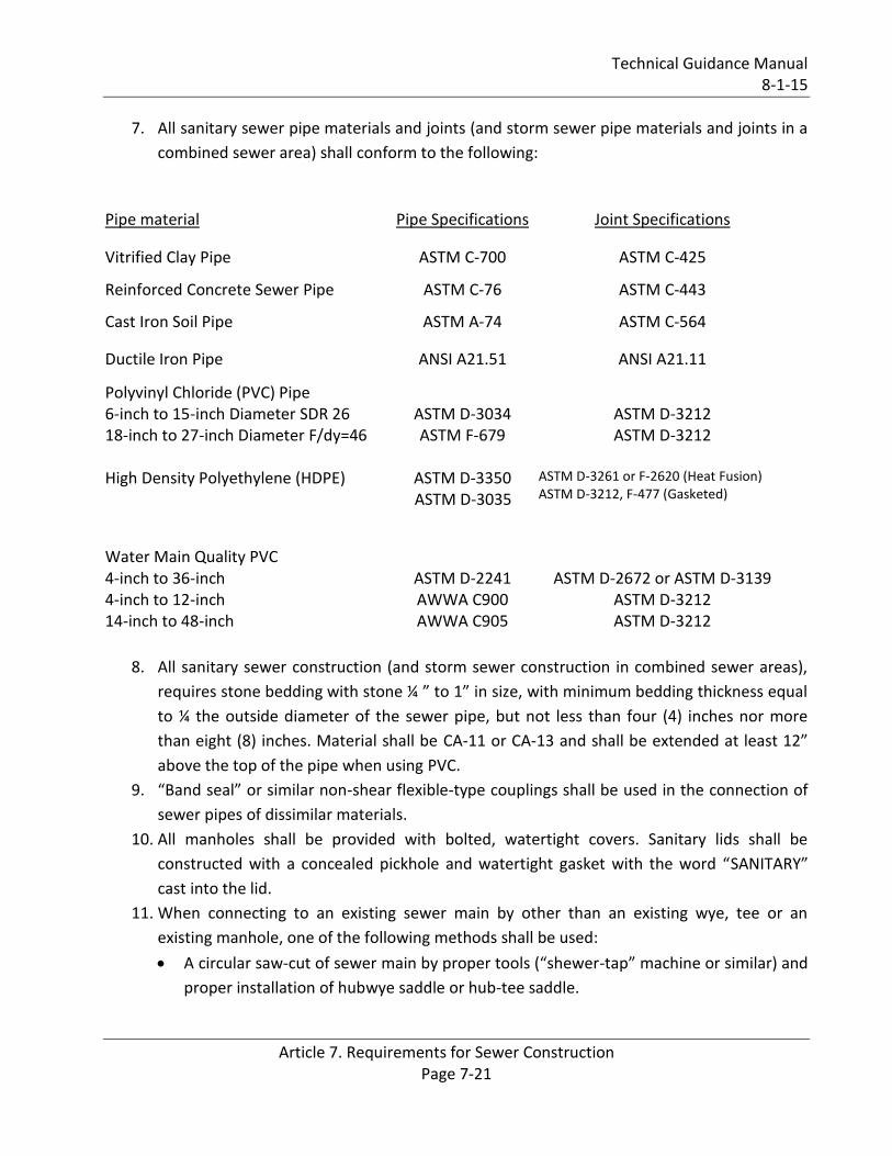
7. All sanitary sewer pipe materials and joints (and storm sewer pipe materials and joints in a
combined sewer area) shall conform to the following:
Pipe material Pipe Specifications Joint Specifications
Vitrified Clay Pipe ASTM C-700 ASTM C-425
Reinforced Concrete Sewer Pipe ASTM C-76 ASTM C-443
Cast Iron Soil Pipe ASTM A-74 ASTM C-564
Ductile Iron Pipe ANSI A21.51 ANSI A21.11
Polyvinyl Chloride (PVC) Pipe 6-inch to 15-inch Diameter SDR 26 18-inch to 27-inch Diameter F/dy=46
ASTM D-3034 ASTM F-679
ASTM D-3212 ASTM D-3212
High Density Polyethylene (HDPE) ASTM D-3350
ASTM D-3035
ASTM D-3261 or F-2620 (Heat Fusion) ASTM D-3212, F-477 (Gasketed)
Water Main Quality PVC 4-inch to 36-inch 4-inch to 12-inch 14-inch to 48-inch
ASTM D-2241 AWWA C900 AWWA C905
ASTM D-2672 or ASTM D-3139
ASTM D-3212 ASTM D-3212
8. All sanitary sewer construction (and storm sewer construction in combined sewer areas),
requires stone bedding with stone ¼ ” to 1” in size, with minimum bedding thickness equal
to ¼ the outside diameter of the sewer pipe, but not less than four (4) inches nor more
than eight (8) inches. Material shall be CA-11 or CA-13 and shall be extended at least 12”
above the top of the pipe when using PVC.
9. “Band seal” or similar non-shear flexible-type couplings shall be used in the connection of
sewer pipes of dissimilar materials.
10. All manholes shall be provided with bolted, watertight covers. Sanitary lids shall be
constructed with a concealed pickhole and watertight gasket with the word “SANITARY”
cast into the lid.
11. When connecting to an existing sewer main by other than an existing wye, tee or an
existing manhole, one of the following methods shall be used:
A circular saw-cut of sewer main by proper tools (“shewer-tap” machine or similar) and
proper installation of hubwye saddle or hub-tee saddle.
Technical Guidance Manual 8-1-15
Article 7. Requirements for Sewer Construction Page 7-22
Remove an entire section of the pipe (breaking only the top of one bell) and replace
with a wye or tee branch section.
With pipe cutter, neatly and accurately cut out desired length of pipe for insertion of
proper fitting, using “band seal” or similar couplings to hold it firmly in place.
12. Whenever a sanitary/combined sewer crosses under a watermain, the minimum vertical
distance from the top of the sewer to the bottom of the watermain shall be 18 inches.
Furthermore, a minimum horizontal distance of 10 feet between sanitary/combined
sewers and watermains shall be maintained unless: the sewer is laid in a separate trench,
keeping a minimum 18” vertical separation; or the sewer is laid in the same trench with the
watermain located at the opposite side on a bench of undisturbed earth, keeping a
minimum 18” vertical separation. If either the vertical or horizontal distances described
above cannot be maintained, or the sewer crosses above the watermain, the sewer shall
be constructed to watermain standards.
13. All existing septic systems shall be abandoned. Abandoned tanks shall be filled with
granular material or removed.
14. All sanitary manholes, (and storm manholes in combined sewer areas), shall have a
minimum inside diameter of 48 inches, and shall be cast in place or pre-cast reinforced
concrete.
15. All sanitary manholes, (and storm manholes in combined sewer areas), shall have precast
“rubber boots” that conform to ASTM C-923 for all pipe connections. Precast sections shall
consist of modified groove tongue and rubber gasket type joints.
16. All abandoned sanitary sewers shall be plugged at both ends with at least 2 feet long non-
shrink concrete or mortar plug.
17. Except for foundation/footing drains provided to protect buildings or perforated pipes
associated with volume control practices, drain tiles/field tiles/underdrains/perforated
pipes are not allowed to be connected to or tributary to combined sewers, sanitary sewers,
or storm sewers tributary to combined sewers in combined sewer areas. Construction of
new facilities of this type is prohibited; and all existing drain tiles and perforated pipes
encountered within the project area shall be plugged or removed, and shall not be
connected to combined sewers, sanitary sewers, or storm sewers tributary to combined
sewers.
18. A backflow preventer is required for all detention basins tributary to combined sewers.
Required backflow preventers shall be inspected and exercised annually by the property
owner to ensure proper operation, and any necessary maintenances shall be performed to
ensure functionality. In the event of a sewer surcharge into an open detention basin
tributary to combined sewers, the permittee shall ensure that clean up and wash out of
sewage takes place within 48 hours of the storm event.
Technical Guidance Manual 8-1-15
Article 7. Requirements for Sewer Construction Page 7-23
Specifications. When specifications are prepared for the project separate from the plan sheets,
submit one (1) copy of the specifications covering or relating to the sewer work, upon request.
The specifications shall indicate the name of the project, and the name and address of the design
engineer and shall contain a table of contents. The specifications table of content page shall be
signed and sealed with original signatures and seals by a licensed Professional Engineer in the
State of Illinois.
Technical Guidance Manual 8-1-15
Article 7. Requirements for Sewer Construction Page 7-24
REFERENCES
American Concrete Pipe Association. 2011. Concrete Pipe Design Manual. Available at: http://www.concrete-pipe.org/pdf/cp-manual.pdf American Society of Civil Engineers. 2007. Manual of Practice No. 60, Gravity Sanitary Sewer
Design and Construction
American Society of Civil Engineers. 2012. Manual of Practice No. 87, Design of Urban Stormwater
Controls
American Society for Testing and Materials (ASTM) Standards. Available at: www.astm.org
American Water Works Association (AWWA) Standards. Available at: www.awwa.org
Ductile Iron Pipe Research Association. 1984. Ductile Iron Pipe Handbook. www.dipra.org/publications East Jordon Iron Works, www.americas.ejco.com
Illinois Department of Transportation. 2011. Drainage Manual. Available at: http://www.dot.il.gov/bridges/pdf/IDOT%20DRAINAGE%20MANUAL.pdf Metcalf & Eddy. 1972. Wastewater Engineering: Collection, Treatment, Disposal.
Metropolitan Water Reclamation District of Greater Chicago. Combined Sewer Atlas. (Order from the Engineering Department Vault) Metropolitan Water Reclamation District of Greater Chicago. MWRD Facilities Atlas (Order from the Engineering Department Vault) Neenah Foundry Company, www.nfco.com Standard Specifications for Water & Sewer Construction in Illinois State of Illinois Administrative Code: Title 35: Environmental Protection, Subtitle C: Water Pollution
Chapter II: Environmental protection Agency Part 370: Illinois Recommended Standards for Sewage
Works.
State of Illinois Plumbing Code. Available at: http://www.ilga.gov/commission/jcar/admincode/077/07700890sections.html Uni-Bell PVC Pipe Association. 1979. Handbook of PVC Pipe Available at: www.uni-bell.org
Technical Guidance Manual 8-1-15
Article 7. Requirements for Sewer Construction Page 7-25
US Department of Agriculture Natural Resources Conservation Service. 2012. Illinois Urban Manual: A Technical Manual Designed for Urban Ecosystem Protection and Enhancement. Available at: http://www.nrcs.usda.gov/wps/portal/nrcs/main/il/technical/ US Department of Agriculture, Natural Resources Conservation Service. 2004. National Engineering Handbook. Available at: http://www.nrcs.usda.gov/wps/portal/nrcs/detailfull/national/water/?cid=stelprdb1043063
Water Environment Foundation. 1993. Design of Wastewater and Stormwater Pumping Stations,
Manual of Practice.