arthrodesis of the ankle -...
TRANSCRIPT

TMTMTMTMTMTMTMTMTMTMTMTMTMTMTMTMM
Arthrodesis of the Ankle

Plantar View of the Foot
1. Make a lateral incision to expose the tibia-talus joint and
the talo-calcaneal joint. Prepare the arthrodesis sites
surgically with a rasp or an osteotome to denude the
arthrodesis sites for better union.
2. Make a plantar incision to expose the calcaneus for the
insertion of a 2.5x300 mm Steinman pin, to serve as the
“guide wire” for all subsequent steps.
Drive Guide Wire
3. Align the tibia over the talus in the desired position before
advancing the Steinman pin through either joint. The use
of a C-arm is essential. The Steinman pin should be
centered with respect to both the talus and the tibia.
This step may require a slight forward shift of the tibia.
Advance the Steinman pin according to the following
guide. Stop advancing the Steinman pin after the
corresponding limit for each FUZE length is reached.
THE VILEX FUZE – ARTHRODESIS OF THE ANKLE

Drill FuzeTM Path
4. Use a cannulated 7.5 mm drill with 2.5 mm cannulation
to drill a hole from the plantar surface of the calcaneus
through the talus and the articular surface of the tibia.
Visualize the progress of the drill. The drill should reach
the intramedullary canal of the tibia.
5. Remove the drill and use a cannulated orthopedic
reamer to clear a path for the implant within the
intramedullary canal. Start with the smallest reamer
diameter and go to the next size depending on the
FUZE size. The reamed hole diameter should not
exceed the minor diameter of the implant’s thread.
6. Push the foot against the tibia to compress the joints manually
and to close the tibia-talus and talus-calcaneus gaps.
THE VILEX FUZE – ARTHRODESIS OF THE ANKLE

Implant FuzeTM
7. Insert the implant and drive it manually with the 5.5 mm hex
cannulated screwdriver.
Stop Advancing
8. Before the implant head reaches the calcaneus, and while the
implant head is at least 20 mm outside the foot, remove the
Steinman pin altogether and lock the hex screwdriver to the
FUZE. Note the FUZE and the screwdriver lock together in
only one position. Make sure there is no foreign material within
the head cavity that might
cause misalignment.
Remove Guide Wire
THE VILEX FUZE – ARTHRODESIS OF THE ANKLE

THE VILEX FUZE – ARTHRODESIS OF THE ANKLE

Lock Driver to FuzeTM
THE VILEX FUZE – ARTHRODESIS OF THE ANKLE

THE VILEX FUZE – ARTHRODESIS OF THE ANKLE
Lock Driver to FuzeTM
9. Continue to advance the FUZE with the hex screwdriver.
10. When the middle thread of the implant engages the distal
tibia and the head engages the calcaneus, the talus-tibia and
talus-calcaneus joints tighten at first. When the middle thread
clears the talus, the implant compresses the joints.
11. Advance the implant until the FUZE head is flush with the
bone surface. The notch in the hex screwdriver handle
should face towards the toes.
Attaching Targeting Tool
12. Attach the Targeting Frame/Jig to the
FUZE head. Align the notch of the
implant with the protrusion pin in the
middle leg of the metal support of
the Targeting Frame/Jig.

Attaching Targeting Tool
THE VILEX FUZE – ARTHRODESIS OF THE ANKLE
Alignment Notch

Targeting Tool Mounted
THE VILEX FUZE – ARTHRODESIS OF THE ANKLE

Targeting Tool Mounted
THE VILEX FUZE – ARTHRODESIS OF THE ANKLE

Targeting Tool Locked
THE VILEX FUZE – ARTHRODESIS OF THE ANKLE
NOTE: The FUZE-screwdriver assembly
locks into the Targeting Frame/Jig in
only one position. Tighten the locking
nut to secure the Targeting Frame/Jig
to the FUZE-hex screwdriver assembly.
Locking Nut

Targeting Tool Locked
THE VILEX FUZE – ARTHRODESIS OF THE ANKLE
Locking Nut
Plantar View

Introducing Locking Screws
9. Insert the 150 mm drill guide
P460-35A into a proximal
Targeting Frame/Jig hole
(corresponding to the leading
tip of the implant). Insert a
3.5 mm drill, Z400-150-35,
into the drill guide and drive it
into the tibia, through the FUZE,
and into the distal wall of the
tibia. The drilling provides a pilot
hole for the 5.0 mm locking
screws.
THE VILEX FUZE – ARTHRODESIS OF THE ANKLE
Proximal LM Hole Distal LM Hole
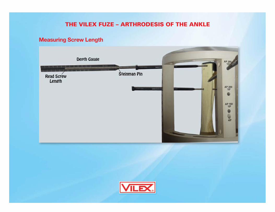
Measuring Screw Length
THE VILEX FUZE – ARTHRODESIS OF THE ANKLE

THE VILEX FUZE – ARTHRODESIS OF THE ANKLE
Introducing Locking
Screws
14. Insert the 150 mm drill
guide P460-35A into
a proximal Targeting
Frame/Jig hole
(corresponding to the
leading tip of the
implant). Insert a
3.5 mm drill,
Z400-150-35, into
the drill guide and
drive it into the tibia, through the FUZE, and into the distal wall of the tibia.
The drilling provides a pilot hole for the 5.0 mm locking screws.
THE VILEX FUZE – ARTHRODESIS OF THE ANKLE
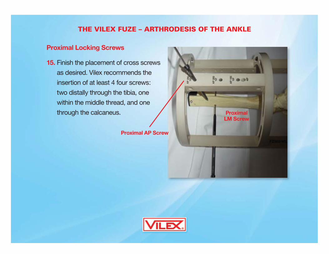
Proximal Locking Screws
15. Finish the placement of cross screws
as desired. Vilex recommends the
insertion of at least 4 four screws:
two distally through the tibia, one
within the middle thread, and one
through the calcaneus.
Proximal AP Screw
LM ScrewProximal

THE VILEX FUZE – ARTHRODESIS OF THE ANKLE
Distal Locking Screws
16. Add more screws as
desired. Screw the end
cap and close.
Distal LM ScrewDistal LM Screw
Distal LM Screw

THE VILEX FUZE – ARTHRODESIS OF THE ANKLE
Distal Locking Screws
16. Add more screws
as desired. Screw
the end cap and
close.
Inserting Slanted Screw From Talus to Calcaneus

THE VILEX FUZE – ARTHRODESIS OF THE ANKLE
Distal Locking Screws
16. Add more screws
as desired. Screw
the end cap and
close.
Advance Drill through Heal & Retrograde

THE VILEX FUZE – ARTHRODESIS OF THE ANKLE
All Screws Inserted
Fibula Removed

THE VILEX FUZE – ARTHRODESIS OF THE ANKLE
The FuzeTM Tray
Tray Cover

THE VILEX FUZE – ARTHRODESIS OF THE ANKLE
The FuzeTM Tray
Top Tray

THE VILEX FUZE – ARTHRODESIS OF THE ANKLE
The FuzeTM Tray
Lower Tray
Screw Tray
y
Lower TrayLower Tray