arta emergency release breakaway emergency release...
TRANSCRIPT
Page 1
ARTA GmbH & Co. KG; P.O. Box 1248; D-65571 Diez - Germany; Tel.:+49-6432-9147-40, Fax: +496432-9147-12; e-mail: [email protected]
ARTA Emergency Release Breakaway
Emergency Release Coupling
Type NTS-PU Series (Pull-Away)
Sizes (6”- 12’’) DN150 – DN300

Page 2
ARTA GmbH & Co. KG; P.O. Box 1248; D-65571 Diez - Germany; Tel.:+49-6432-9147-40, Fax: +496432-9147-12; e-mail: [email protected]
Page
Content 2
1.0 Description Emergency Release Breakaway 3
1.1 Area of use 31.2 Design 31.3 Function 31.4 Advantages 31.5 Materials 41.6 Technical Data 41.7 Approvals 4
2.0 User manual 5
2.1 Installment 52.2 Reassembly after separation 52.3 Assembly / Manual 7 - 14
3.0 Testing- and maintenance recommendation 15
3.1 Test periods of Breakaways 153.2 Test procedure 153.3 Pressure testing of separated halves 153.4 Pressure testing of assembled unit 153.5 Testing of separation force 153.6 Maintenance 153.7 Repairs 153.8 Cleaning procedure 15
Page 3
ARTA GmbH & Co. KG; P.O. Box 1248; D-65571 Diez - Germany; Tel.:+49-6432-9147-40, Fax: +496432-9147-12; e-mail: [email protected]
1.0 Description Emergency Release Breakaway
1.1 Area of use
The Emergency Release Coubling (NTS-PU) can be used in loading arms, hoses- and pipelines forthe transfer of fluids or gas.
Typical application :
Ship loading and unloading Loading arm systems Ship to ship transfer Ship to onshore Onshore and offshore service pipe-lines Subsea manifolds
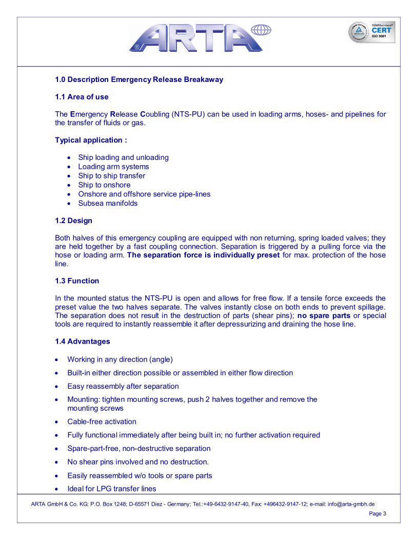
1.2 Design
Both halves of this emergency coupling are equipped with non returning, spring loaded valves; theyare held together by a fast coupling connection. Separation is triggered by a pulling force via thehose or loading arm. The separation force is individually preset for max. protection of the hoseline.
1.3 Function
In the mounted status the NTS-PU is open and allows for free flow. If a tensile force exceeds thepreset value the two halves separate. The valves instantly close on both ends to prevent spillage.The separation does not result in the destruction of parts (shear pins); no spare parts or specialtools are required to instantly reassemble it after depressurizing and draining the hose line.
1.4 Advantages
Working in any direction (angle)
Built-in either direction possible or assembled in either flow direction
Easy reassembly after separation
Mounting: tighten mounting screws, push 2 halves together and remove themounting screws
Cable-free activation
Fully functional immediately after being built in; no further activation required
Spare-part-free, non-destructive separation
No shear pins involved and no destruction.
Easily reassembled w/o tools or spare parts
Ideal for LPG transfer lines

Page 4
ARTA GmbH & Co. KG; P.O. Box 1248; D-65571 Diez - Germany; Tel.:+49-6432-9147-40, Fax: +496432-9147-12; e-mail: [email protected]
1.5 Materials
The following combinations are suggestions depending on the media:
Housing/internals Seals
General chemical use: SS 316 (L / Ti) Elastomer o-rings
Fuels / oils : SS 304 Elastomer o-rings
Subsea : Duplex Elastomer o-rings
Standard elastomer o-rings in FPM (FKM Viton®), EPDM, FFKM (Chemraz® / Kalrez®)Flat seals in PTFE (Teflon®)
Other materials and seal rings upon request
1.6 Specifications
Sizes: 6’’ - 12” (DN150 – DN300)
Pressure rating: 232psi (PN16), 360psi (PN25)
Connections: DIN/ISO-, ASA- flangesOther threads and flanges on request
Separation force suggestions:
Size 6” (DN150) 8” (DN200) 10” (DN250) 12” (DN300)
WP – 0 bar 22046 lbs
(10 t)
33069 lbs
(15 t)
44092 lbs
(20 t)
55115 lbs
(25 t)
Special sizes available on request
1.7 Approvals
CE-marked, Type-examination (Module B) according to Directive 97/23/EC ATEX, Manufactures Certificate of conformance according to Directive 94/9/EC (ATEX) Conform with clean air regulation (TA-Luft) Manufactured under DIN EN ISO 9001:2008

Page 5
ARTA GmbH & Co. KG; P.O. Box 1248; D-65571 Diez - Germany; Tel.:+49-6432-9147-40, Fax: +496432-9147-12; e-mail: [email protected]
2.0 User Manual - NTS-PU
2.1 Installment:
1. To assure a safe function the NTS-PU needs to be installed as follows:a. Tensile force either axial or at an angleb. The coupling halves need to have enough space to fully separate.
This guarantees the complete closure of the valves.
For all sizes 6” - 12” (DN150 – DN300) the minimal required distance between the twohalves is 8’’ (200mm) at the point of separation.
2. The ARTA NTS-PU can be installed in any direction.
3. Installation should not lead to stress on the production line.
4. Mounting screws must be removed before the use of the NTS-PU
5. During the separation small amounts of media could escape. We therefore recommend anadditional spray protection.
6. The user manual (installation instructions) and the mounting screws should be kept in secureand accessible location.
Caution!The Valves of the NTS-PU are spring loaded.
Inappropriate disassembly could lead to injuries!
7. Warning !!!!!!!!!!
During the (un)fueling process no person should be standing in the danger zone of the NTS.The separated hose end might pose an injury danger during the separation process.Emergency contingencies are to be followed according to local regulations and jurisdictions.

Page 6
ARTA GmbH & Co. KG; P.O. Box 1248; D-65571 Diez - Germany; Tel.:+49-6432-9147-40, Fax: +496432-9147-12; e-mail: [email protected]
2.2 Reassembly of the NTS-PU after separation
1. Depressurize and empty the hose / loading arm
2. Inspect both coupling halves for possible damage
3. Check valves manually for easy function
4. Evenly apply mounting screws to release levers
5. Place the two valve pins on top of each other and press the top halve downward into the bottomhalve. Then carefully remove the mounting screws while still holding down the top halve untilthe connecting elements engage
6. Do not conduct the final leakage test with air

Page 7
ARTA GmbH & Co. KG; P.O. Box 1248; D-65571 Diez - Germany; Tel.:+49-6432-9147-40, Fax: +496432-9147-12; e-mail: [email protected]
2.3 Assembly / Manual
1. We recommend for the transport eyebolts and suitable lifting belts
2. Use a suitable lifting device and a solid frame for the assembly !!!!!!!!!!
lifting belts
eyebolts

Page 8
ARTA GmbH & Co. KG; P.O. Box 1248; D-65571 Diez - Germany; Tel.:+49-6432-9147-40, Fax: +496432-9147-12; e-mail: [email protected]
3. Screw in (assemble) the allen screws. The lever then opens to allow reconnection
4. Screw in the four threaded rods
lever
allen screws
Attention !!!!!!Do not removethese screws
threaded rods
The opposite side is mirror invented

Page 9
ARTA GmbH & Co. KG; P.O. Box 1248; D-65571 Diez - Germany; Tel.:+49-6432-9147-40, Fax: +496432-9147-12; e-mail: [email protected]
5. Mount the adapter and the Inline
inline
adapter
The opposite side is mirror invented

Page 10
ARTA GmbH & Co. KG; P.O. Box 1248; D-65571 Diez - Germany; Tel.:+49-6432-9147-40, Fax: +496432-9147-12; e-mail: [email protected]

Page 11
ARTA GmbH & Co. KG; P.O. Box 1248; D-65571 Diez - Germany; Tel.:+49-6432-9147-40, Fax: +496432-9147-12; e-mail: [email protected]
6. Remove the allen screws
allen screws
Attention !!!!!!Do not removethese screws
The opposite side is mirror invented

Page 12
ARTA GmbH & Co. KG; P.O. Box 1248; D-65571 Diez - Germany; Tel.:+49-6432-9147-40, Fax: +496432-9147-12; e-mail: [email protected]

Page 13
ARTA GmbH & Co. KG; P.O. Box 1248; D-65571 Diez - Germany; Tel.:+49-6432-9147-40, Fax: +496432-9147-12; e-mail: [email protected]
7. Mount the protective tube
8. Remove the (four) threaded rods
protective tube
threaded rodsto be removed
The opposite side is mirror invented

Page 14
ARTA GmbH & Co. KG; P.O. Box 1248; D-65571 Diez - Germany; Tel.:+49-6432-9147-40, Fax: +496432-9147-12; e-mail: [email protected]
9. The system is complete
10. Mount the spool pice
spool piece

Page 15
ARTA GmbH & Co. KG; P.O. Box 1248; D-65571 Diez - Germany; Tel.:+49-6432-9147-40, Fax: +496432-9147-12; e-mail: [email protected]
3.0 Test – and Maintenance recommendations – NTS-PU
3.1 Test periods of the Emergency Release Coupler
Independently from governmental regulations, we recommend to test Emergency ReleaseCouplers at least once a year according to the test recommendations for thermoplastic,elastomer-type hoses.
A more vigorous use requires shorter test intervals. Elevated temperatures, higherconcentrations, impurities and abrasive particles can significantly influence the corrosionresistance in Emergency Release Couplers.
3.2 Test procedure
Test procedures are regulated by the local plant safety committee. It could involve for examplepressure test of both coupler halves or the mounted coupler, a separation test and/or visualinspection.The results need to be documented.
3.3 Pressure testing the coupling halves
Test both halves individually (adaptor and inline) for leakage. Mount the threaded end (flange)of the separated halve to the test unit and pressurize the system with fluid up to the requiredworking pressure. Increase the pressure stepwise and check for leakage.
3.4 Pressure testing of the mounted NTS-PU
Close the coupler on one side with a blind threaded end / blind flange and fill with fluid in anupright position. Apply the test connection and pressurize the system to the requested workingpressure. Increase the pressure stepwise and check for leakage.
3.5 Separation testing
Build in the NTS-PU in an axial fashion and trigger the separation with e.g. a cable winch. Theuse of a tensile force meter is recommended.
3.6 Maintenance
All ARTA® Emergency Release Couplers (breakaways) have minimal need for maintenance. Allguiding elements, o-rings and seal rings should be periodically checked for porosity as well asfor wear and tear.
Upon request, we can train the operating staff.
Spare parts for ARTA® Emergency Release Couplers (breakaways) can be ordered with therespective part number and product identification which can be found engraved onto thecoupler.
3.7 Repairs
Repairs to the ARTA® Emergency Release Couplers (breakaways) can only be performed bytrained and authorized personnel followed by subsequent testing, labeling and documentation.The spare parts available for many years.
3.8 Cleaning
The NTS-PU needs to be thoroughly cleaned before any repair.