art profileshop plasma v3 - advancedrobotic.com profileshop plasma... · art profileshop v3 5 ......
TRANSCRIPT

ART CNC Profile Cutter
ART ProfileShop© Operating Manual V3 May 2005
Advanced Robotic Technology Pty Ltd 57 Trade Street, Lytton Queensland 4178, Australia
Phone +61 7 3393 6555 Fax +61 7 3393 6533
www.advancedrobotic.com [email protected]

ART ProfileShop V3
2

ART ProfileShop V3
3
Index
List of Features .................................................................................................................. 8
General Safety Instructions .............................................................................................. 9
Precautions to Take When Using Your Profile Cutter .................................................. 11
Before Getting Started ..................................................................................................... 12
Quick Start Guide to ART Profileshop V3 ...................................................................... 13 How Do I Turn the Machine On? ........................................................................................................... 13 How Do I Turn the Machine Off? ........................................................................................................... 13 How Do I Load a Tool? .......................................................................................................................... 13 Selecting a Work Cell ............................................................................................................................ 14 Setting Up a Work Cell .......................................................................................................................... 14 How Do I Load a Job? ........................................................................................................................... 15 How Do I Cut a Job? ............................................................................................................................. 15 How Do I Pause a Job? ......................................................................................................................... 16 How Do I Continue a Job? .................................................................................................................... 16 How Do I Quit a Job and Return to the Origin? ..................................................................................... 16 How Do I Recover a Partially Completed Job? ..................................................................................... 17 How Do I Skip to a Specific Shape? ...................................................................................................... 17 How Do I Cut Only Part of the Job? ...................................................................................................... 18
The Pendant Features and Operation ............................................................................ 19 Accessing Features ............................................................................................................................... 19
ART ProfileShop Software .............................................................................................. 20
Menus ............................................................................................................................... 22 File Menu ............................................................................................................................................... 22
New ............................................................................................................................................. 22 Open ............................................................................................................................................ 22 Refresh List ................................................................................................................................. 23 Filter ............................................................................................................................................ 23 Save ............................................................................................................................................ 25
Select Menu ........................................................................................................................................... 26 Select .......................................................................................................................................... 26 Add .............................................................................................................................................. 26 Subtract ....................................................................................................................................... 26 All ................................................................................................................................................ 26 None ............................................................................................................................................ 26 Invert All ...................................................................................................................................... 27 Same ........................................................................................................................................... 27 Wizard ......................................................................................................................................... 27 Tool ............................................................................................................................................. 27 Size ............................................................................................................................................. 28 Position ........................................................................................................................................ 28 Depth ........................................................................................................................................... 28 Select .......................................................................................................................................... 28
Draw Menu ............................................................................................................................................ 29 Stop ....................................................................................................................................................... 29 Modify Menu .......................................................................................................................................... 29
Select .......................................................................................................................................... 29 Move ............................................................................................................................................ 29 Copy ............................................................................................................................................ 30 Array ............................................................................................................................................ 31 Rotate .......................................................................................................................................... 32

ART ProfileShop V3
4
Resize ......................................................................................................................................... 32 Delete .......................................................................................................................................... 33
Origin Menu ........................................................................................................................................... 33 Mode ........................................................................................................................................... 33 Move To ...................................................................................................................................... 33
Move XY to ....................................................................................................................... 33 Cell Origin ......................................................................................................................... 33 Job Extents ....................................................................................................................... 33 Home Limits ...................................................................................................................... 33 Cell Park ........................................................................................................................... 33 Move Z to .......................................................................................................................... 34 Travel ................................................................................................................................ 34 Surface .............................................................................................................................. 34
Proportional Jog Pad ................................................................................................................... 34 Set ............................................................................................................................................... 34 Set XY ......................................................................................................................................... 34 Set Z ............................................................................................................................................ 35 Z = Bottom ................................................................................................................................... 35 Align ............................................................................................................................................ 35 Level ............................................................................................................................................ 36 Set All .......................................................................................................................................... 36 Clear All ....................................................................................................................................... 36 Set Park ....................................................................................................................................... 36
Cut Job Menu ........................................................................................................................................ 37 Mode ........................................................................................................................................... 37 Auto ............................................................................................................................................. 37 Job Control Function Buttons ...................................................................................................... 38
Previous ............................................................................................................................ 38 Rewind .............................................................................................................................. 38 Reverse ............................................................................................................................. 39 Stop ................................................................................................................................... 39 Cut..................................................................................................................................... 39 Fast Forward ..................................................................................................................... 39 Next ................................................................................................................................... 39 Feed Rate Override .......................................................................................................... 39
Mode ........................................................................................................................................... 40 Recover ............................................................................................................................. 40 Jog Controls ...................................................................................................................... 40 Move Start Point ............................................................................................................... 40 Nearest Start ..................................................................................................................... 40 Shape Start ....................................................................................................................... 40 Park Position ..................................................................................................................... 41 Nearest Path ..................................................................................................................... 41 Work Cell Origin ................................................................................................................ 41
Tools Menu ............................................................................................................................................ 42 Edit .............................................................................................................................................. 42 Edit Tool Path Dialog Box ........................................................................................................... 42 Tool Parameters List ................................................................................................................... 42 Load Strategy .............................................................................................................................. 42 Save Strategy .............................................................................................................................. 43 Reset ........................................................................................................................................... 43 OK ............................................................................................................................................... 43 Cancel ......................................................................................................................................... 43 Tool # .......................................................................................................................................... 43
Parameters ............................................................................................................................................ 44 Initial Height Sensing .................................................................................................................. 45 Sensor Height.............................................................................................................................. 45

ART ProfileShop V3
5
Pierce Height ............................................................................................................................... 45 Cut Height ................................................................................................................................... 45 Min Sense Dist. ........................................................................................................................... 45 AVC Controls............................................................................................................................... 46 Avc Speed (%) ............................................................................................................................ 46 Avc Volts ..................................................................................................................................... 46 Avc Off (%) .................................................................................................................................. 46 Avc Min Radius ........................................................................................................................... 46 Accessories ................................................................................................................................. 46 Select New Tool .......................................................................................................................... 47 Set As Tool X .............................................................................................................................. 47 Close Library ............................................................................................................................... 47
Library .................................................................................................................................................... 48 All Tools ....................................................................................................................................... 48 Picture Box .................................................................................................................................. 49 Description .................................................................................................................................. 49 Parameters .................................................................................................................................. 49 Changer ....................................................................................................................................... 49 Load ............................................................................................................................................ 49 Load Tool .................................................................................................................................... 49 Unload ......................................................................................................................................... 49 Sense .......................................................................................................................................... 49 Sense Tools ................................................................................................................................ 49 Sense Now .................................................................................................................................. 50
T/Head 1 ................................................................................................................................................ 50 Setup ..................................................................................................................................................... 50 Info ......................................................................................................................................................... 50 User Login ............................................................................................................................................. 50
Troubleshooting .............................................................................................................. 51 Control Console Will Not Boot Up — No Movement ............................................................................. 51 Inaccuracy in Cutting ............................................................................................................................. 51 Cut Is Not Square or Is Not Meeting Up ................................................................................................ 51 Cuts Wrong — Does Not Cut According to the File .............................................................................. 51 Machine Starts but Pendant Display or Buttons Do Not Work .............................................................. 51
Machine Maintenance ...................................................................................................... 52 Routine Mainteince. ............................................................................................................................... 52 Lubricating the Machine ........................................................................................................................ 52 X Axis Grease Points............................................................................................................................. 52 Y Axis Grease Points............................................................................................................................. 52 Z Axis Grease Points ............................................................................................................................. 53 Z-Screw Grease Point ........................................................................................................................... 53 Custom Machines .................................................................................................................................. 53 Adjustments ........................................................................................................................................... 53 Specialised Accessories ........................................................................................................................ 53 Vacuum Pumps ..................................................................................................................................... 53 Dust Extraction ...................................................................................................................................... 53 Coolant Systems ................................................................................................................................... 53 Air Supply .............................................................................................................................................. 54
Appendix A — Router G CODE ....................................................................................... 55
Appendix B — Plasma G CODE ...................................................................................... 58
Appendix C — Warranty Conditions .............................................................................. 61 Advanced Robotic Technology Pty Ltd Warranty Conditions ............................................................... 61 Appendix D — Warranty Form (Customer Copy) ............................................................................. 63 Appendix E — Warranty Form (ART Copy) ...................................................................................... 65

ART ProfileShop V3
6
Non Conformance Reports ............................................................................................. 67 NCR Instructions ................................................................................................................................... 67 NCR’s .................................................................................................................................................... 69

ART ProfileShop V3
7
Introduction
Thank you for purchasing an ART CNC Profile Cutter.
Each of the profilers in the Advanced Robotic Technology (ART) series is designed to be one of the most versatile cutting machines on the market. The profilers can be used for such diverse jobs as sign-writing, cabinet-making, engraving, sheet-metal work, steel fabrication, mould-making, plastic fabrication and many more.
The profile cutter uses tool-pathing software such as ENROUTE® or PROFILE MASTER®. This software creates G code that outlines the path for the machine to take. It must be set up to suit the machine. The tool-pathing software normally places your part on a sheet. The bottom left hand side of this sheet is known as your 0,0 or point of origin. This point is important because it corresponds with the point of origin that is set on the machine by the user.
We are sure you will enjoy many years of trouble-free manufacturing; however, if any difficulties are experienced please consult the trouble-shooting section of this manual which lists solutions to the most common problems. If the problem is not listed in this manual please contact Advanced Robotic Technology via the numbers on the front of this manual.
ART ProfileShop V3
8
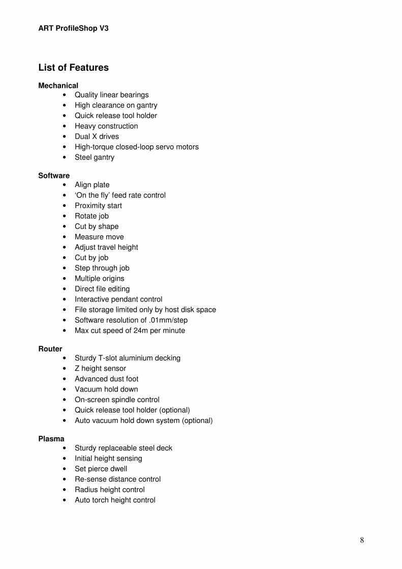
List of Features Mechanical
• Quality linear bearings
• High clearance on gantry
• Quick release tool holder
• Heavy construction
• Dual X drives
• High-torque closed-loop servo motors
• Steel gantry
Software
• Align plate
• ‘On the fly’ feed rate control
• Proximity start
• Rotate job
• Cut by shape
• Measure move
• Adjust travel height
• Cut by job
• Step through job
• Multiple origins
• Direct file editing
• Interactive pendant control
• File storage limited only by host disk space
• Software resolution of .01mm/step
• Max cut speed of 24m per minute
Router
• Sturdy T-slot aluminium decking
• Z height sensor
• Advanced dust foot
• Vacuum hold down
• On-screen spindle control
• Quick release tool holder (optional)
• Auto vacuum hold down system (optional)
Plasma
• Sturdy replaceable steel deck
• Initial height sensing
• Set pierce dwell
• Re-sense distance control
• Radius height control
• Auto torch height control

ART ProfileShop V3
9
General Safety Instructions When using machinery always observe the safety regulations applicable in your country to reduce the risk of fire, electric shock and personal injury. Read the following safety instructions before attempting to operate this machine. Please make this information available to all staff involved in operating the machine. 1. Keep the work area clean. Cluttered areas can cause accidents. 2. Consider the work area environment. Do not expose equipment to high humidity or rain.
Keep the work area well lit. Do not use equipment in the presence of flammable liquids or gases.
3. Guard against electric shock. All power leads should be placed where the risk of tripping is
minimal, and the plasma cutter should be wired into the building by a licensed electrician. 4. Do not abuse leads. Keep the leads away from heat, oil and sharp edges. 5. Keep all unauthorised people away from the work area. 6. Dress correctly. Do not wear loose clothing or jewellery. They can get caught in moving
parts. Wear protective hair covering to keep long hair out of moving parts. 7. Use safety goggles. 8. Use a dust mask if the operations produce dust fumes. 9. Be aware of maximum sound pressure. Take appropriate measures for the protection of
hearing if 85dB(A) is exceeded. 10. Do not over-reach; always keep proper footing and balance. 11. Stay alert. Watch what you are doing. Use common sense. Do not operate when you are
tired or under the influence of alcohol or drugs. 12. Secure the work-piece. Use clamps or a vice to hold it — never use hands. 13. When using the vacuum always be conscious of its limitations (e.g. part size, porosity and
material to be cut). 14. Avoid unintentional starting. Be aware that the machine is programmed to start automatically.
Keep well away from the machine when it is cutting. 15. Before leaving the machine unattended for servicing or to change accessories disconnect the
machine. Wait for the machine to come to a complete standstill and shut off the power. 16. When not in use, consumables and tools must be stored in a clean, dry area and be locked
up securely. In humid climates care should be taken that condensation does not develop. Keep susceptible parts covered in a thin film of lubricant to prevent rust.

ART ProfileShop V3
10
17. Use appropriate consumables. The use of any accessories or attachments other than the ones recommended may result in a risk of personal injury or damage to the machine.
18. Maintain and clean equipment to ensure better and safer performance. Follow the
instructions for maintenance and changing accessories. Inspect equipment at regular intervals and, if damaged, have them repaired by an authorised technician. Inspect cords periodically and replace them if damaged. Keep all controls dry and clean.
19. Before using the equipment always carefully check for damage and worn parts to ensure it
will operate properly and perform its intended function. Check for misalignment, seizure of moving parts, broken parts or any other conditions that may affect its operation. Have damaged guards or other defective parts repaired or replaced. Do not use the machinery if defective.
20. This electrical equipment is designed in accordance with the relevant safety regulations. To
avoid danger, electrical equipment must only be repaired by qualified technicians. Do not access any electrical areas if you have not been properly trained.

ART ProfileShop V3
11
Precautions to Take When Using Your Profile Cutter Transporting
Never lift the machine with a forklift without checking the position of the data chain and the control box. Serious damage can occur because of incorrect handling.
Preparation for Use
Many people place a sacrificial material on top of the standard deck to prevent damage to the deck from cutting. If you use a semi-permanent material (i.e. that is left on for many jobs) then it is advised that you use plastic bolts to hold it down. This will prevent serious damage to the cutting tool should it cut into the bolt. If normal screws or bolts are used, careful placement is necessary to avoid collisions.
Loading Material
Be careful not to strain yourself when loading materials as these can be quite heavy. Always get assistance if your materials are heavy. Make sure the material is firmly clamped in position as loose material can cause injury.
Safety Equipment
All machinery can be potentially dangerous if proper care is not taken. Eye, ear and respiratory protection are absolutely essential. It is also recommended that gloves be worn. When the machine is in operation keep all body parts and clothing away from moving parts. Become familiar with the location of the emergency stop button and the pause button on the pendant. Use commonsense when operating the machine.
Dust and Fume Extraction
It is your (the user’s) responsibility to ensure that proper ventilation and extraction is provided and used. Many states and countries have guidelines or laws governing environmental issues. Disposal of waste, gases and dust is an issue you should address.
Unloading Jobs
Use care when unloading jobs, especially those that are metal or laminate as such material can produce sharp edges when cut.
Cleaning
Always clean the machine after use by removing debris and vacuuming dust from the deck and the moving parts. Use a light silicone oil on the rails and wipe them with a clean cloth. Regularly doing this will ensure a long service life with few problems. Compressed air is not recommended for cleaning.

ART ProfileShop V3
12
Before Getting Started 1. Place the machine and all the peripherals in the desired position. Ensure that the machine is
level.
2. Attach the pendant lead and all the peripherals to the machine.
3. The placement of your control console will affect how you use the machine. It is recommended that you place the control console close to the machine so that you can access all the advanced features through the control console. Connect the communication leads to the control box and to two free com-ports on your control console. The standard length of serial cables is 10 metres. If you need to lengthen these leads, please speak to ART.
4. Ensure that your mains power has a neutral. Connect the mains power lead and switch it on.
Important note: Ensure 3 phase is connected in the correct phase order for the rotational direction of the vacuum pump/s (if applicable).
5. The machine is a very sophisticated piece of computer-controlled equipment. It is very important that it be provided with a clean supply of electricity. Failure to do so may cause the machine to operate incorrectly. ART is not responsible for any damages that may occur if the machine is not supplied with clean electricity. If you suspect you have a problem with interference you may need to contact a qualified technician in a suitable field. ART can advise you of a suitable technician in your area.

ART ProfileShop V3
13
Quick Start Guide to ART Profileshop V3
How Do I Turn the Machine On? 1. Turn on all of the wall switches, including the ones for the peripherals (i.e. extraction devices,
vacuum pumps etc.).
2. Turn on the control box.
3. Turn on the PC interface.
4. Start ART ProfileShop by double clicking on this icon.
How Do I Turn the Machine Off?
1. Click on the ‘X’ at the top of the control console screen.
2. The control console will ask if it is safe to shut down. Select ‘YES’.
3. If an auto-change tool is loaded, the control console will unload it. If a manual tool is loaded, the control console will ask you to unload it manually.
4. The control console will again ask if you wish to shut down. Select ‘YES’.
5. Click on ‘START’ and then ‘TURN OFF COMPUTER’.
6. Turn off all of the power switches.
How Do I Load a Tool? You do not normally need to load a tool yourself. Two exceptions are as follows:
1. if you want to set up a work cell
2. if you want to change a tool while cutting.
To load a specific tool you do one of the following:
On the pendant:
1. Scroll to TOOL MENU and select ‘TICK’
2. Select ‘LOAD TOOL’
3. Scroll to the desired tool number and select ‘TICK’
4. The machine will load the tool automatically (or ask you to insert it if it is a manual tool of plasma consumables).

ART ProfileShop V3
14
Selecting a Work Cell To set up a work cell you must first select which one you want to work with.
To select a work cell on the pendant:
1. select the ‘ORIGIN’ tab
2. select a cell
3. scroll and press ‘TICK’.
CAUTION: When selecting a work cell on the pendant the machine will immediately move to the previously set coordinates.
There are two ways to select a work cell on the screen. The first is as follows:
1. select the ‘ORIGIN’ tab
2. using ‘SELECT WORK CELL’ scroll to the desired work cell and highlight it.
Note: For safety reasons, when selecting a work cell on the screen the machine will not automatically move to the coordinates as you can see where the job is positioned by looking at the screen.
Alternatively, the second way to select a work cell on the screen is as follows:
Make sure you are in the MAIN MENU and then double click on the desired work-cell number in the graphical display.
Setting Up a Work Cell The work cell must be set up before any machining can be done. This is vital because the machine must know where the material is. If this is not done correctly, major damage could occur to the machine.
To set up a work cell origin:
1. Select a work cell using one of the procedures in the section above titled Selecting a Work Cell.
2. Load a tool as outlined under the section above titled How Do I Load a Tool?
Following this, you can complete the process either on the pendant or on the screen. On the pendant:
1. Select JOG mode (the ‘JOG’ shortcut button is the fastest way to do this).
2. Jog the tool so that the centre of the tool is precisely above the lower left corner of your material.
3. Press ‘TICK’.
4. Select the ‘XY=0’ shortcut button.
On the screen:
1. Press the ‘ORIGIN’ icon.
2. Using the jog wheel, move the machine to the lower left corner of the material.
3. Click on the ‘XY=0’ button to set the corner of the work cell.
4. To make the head of the machine lift, click on the ‘MOVE Z TO TOP’ button.
5. Click on the ‘MAIN’ icon to return to the main screen.

ART ProfileShop V3
15
Origin Icon Jog Screen
Either of the above processes will automatically enter the work cell X and Y origin coordinates in the ‘ORIGIN’ tab.
Origin Tab
Once you have set up the work cell origin, the X and Y size of the material can be entered manually in the ‘ORIGIN’ tab.
Note: The material size does not limit the movement of the machine. It is used for display purposes only (i.e. to see if the job fits inside the material etc.).
How Do I Load a Job? The following procedure will load a job.
1. Click on the ‘FILE’ icon.
2. Click on the ‘OPEN’ icon.
3. Highlight the correct file in the list.
4. Press ‘PREVIEW’ if you want to check the file.
5. Press ‘OPEN’.
How Do I Cut a Job? The following procedure will cut a job.
On the screen:
1. Make sure you are on the correct work cell.
2. Click on the ‘CUT JOB’ icon.
3. Press the ‘GO’ button.
On the pendant:
1. Scroll to the CUT MENU and press ‘TICK’.
2. Press the ‘CUT’ shortcut.
3. Press the ‘GO’ button.

ART ProfileShop V3
16
Note: Pressing the ‘CUT’ shortcut on the main screen will take you directly to the CUT screen. This is fine for when you are starting a job from the beginning; however, the CUT MENU allows you to use some of the higher functions for recovering a job that has already been started.
How Do I Pause a Job? To pause a job, simply press the ‘STOP’ button either on the pendant or on the screen. You can then exit to the MAIN MENU if you wish. You can make adjustments to the work cell or to other global settings and return to the CUT MENU without losing your position. However, if you wish to load a file or make changes to the existing file, the job will reset to the beginning.
How Do I Continue a Job? To continue a job, simply press the ‘GO’ button on the screen, or the ‘CUT’ shortcut and the green
‘GO’ button (>) on the pendant. The job will continue from the previous position as if nothing has changed.
How Do I Quit a Job and Return to the Origin? To quit a job correctly, before you quit you should recover the origin.
On the pendant:
1. Make sure you are in the CUT MENU (you will already be there if you have just paused a job).
2. Press ‘RECOV’ (recover).
3. Press ‘ORGN’.
4. The machine will lift and return to the work cell origin.
On the screen:
1. Make sure you are in the CUT screen.
2. Click on the ‘RECOVER’ button.
3. Click on the ‘WORK CELL ORIGIN’ button.
4. Click on the ‘MAIN’ icon to return to the main screen.
RECOVER WORK CELL ORIGIN

ART ProfileShop V3
17
How Do I Recover a Partially Completed Job? To resume a job at a random position in the job (e.g. if a cutter broke):
On the pendant:
1. Scroll to the CUT MENU and press ‘TICK’.
2. Select the ‘RECOV’ shortcut (recover).
3. Using the arrows, jog the tool to the position you wish to resume from (it does not matter if the tool is above the job).
4. Press the ‘PATH’ shortcut.
5. The machine will lift and move to the closest position on the path to where you positioned it.
6. Escape from the RECOVER MENU back to the CUT MENU using the ‘X’ button.
7. Press the ‘CUT’ shortcut and press ‘GO’ to resume the job.
8. The machine will continue cutting from that position as if nothing has happened.
On the screen: 1. In the CUT screen, click on the ‘RECOVER’ button.
2. Use the jog wheel to move the machine close to the position where you wish to resume cutting.
3. Click on the ‘NEAREST PATH’ button to move the machine onto the path.
4. Click on the ‘AUTO’ button to return to the main CUT screen.
5. Press ‘GO’ (>).
OR
1. In the RECOVER window, click on the desired point on the screen and hold. When the machine stops moving, release and the machine will find the closest path.
2. Click on the ‘AUTO’ button to return to the main CUT screen.
3. Press ‘GO’ (>).
How Do I Skip to a Specific Shape? You can skip shapes by:
On the pendant:
1. Go to the CUT screen.
2. Where it says PRESS GO TO BEGIN, press ‘UP’ (Λ) or ‘DOWN’ (V) to jump to the start point of the next shape.
3. Continue until you get to the shape required.
4. Press ‘GO’ (>) to begin cutting.
On the screen:
1. Go to the CUT screen.
2. Click on the shape you want to start on.
3. Press ‘GO’ (>).
OR

ART ProfileShop V3
18
1. Go to the CUT screen.
2. Press the ‘NEXT’ (>>) or ‘PREV’ (<<) buttons to skip to the shape required.
3. Press ‘GO’ (>).
How Do I Cut Only Part of the Job? 1. Use the SELECT MENU on the screen to pick out specific shapes (see the section above titled
How Do I Skip to a Specific Shape?).
2. Go to the CUT screen.
3. Ensure that the drop-down box in the RANGE frame shows SELECTED SHAPES (this will happen automatically).
4. Press ‘GO’ (>).

ART ProfileShop V3
19
The Pendant Features and Operation
Accessing Features The pendant uses a menu-within-menu system. Each submenu can be accessed by scrolling through the items listed and pressing the ‘ENTER’ key to select that item/submenu. Once you have accessed a feature you can change the setting by using the ‘UP’ or ‘DOWN’ arrow keys. You can accept the new setting by pressing ‘ENTER’ or cancel it by pressing the ‘ESCAPE’ key. To escape from any submenu, press the ‘ESCAPE’ key to return to the MAIN MENU/ORIGIN MENU.

ART ProfileShop V3
20
ART ProfileShop Software

ART ProfileShop V3
21

ART ProfileShop V3
22
Menus
File Menu From the FILE MENU you can perform normal file operations, such as starting a new job, opening a previously saved job, or saving a current job.
New Selecting the ‘NEW’ button clears the current job and opens a blank job sheet.
Open Selecting the ‘OPEN’ button opens the SELECT FILE window. The SELECT FILE window has the following features:
Drive
The DRIVE drop down–list box displays all of the available drives on the control console, for example, hard drives, CD-ROMS, floppy drives and USB memory sticks.
Do not map drives belonging to other computers.
Folder
Once you have selected a drive, you can select any directory on it in the FOLDER box.
Name
In the NAME box on the left-hand side of the screen, you can select the file you would like to open. Double click on the file to view it in the preview window. Note: You may not be able to view some files in the preview window.
Main/File
Main/File/New
Main/File/Open

ART ProfileShop V3
23
Alternatively, you can type the name of the file you would like to open in the NAME box on the right-hand side of the screen. To view the file in the preview window click on the ‘PREVIEW’ button (also see the instructions below under the heading Preview). Type
Available file extensions can be selected from the TYPE drop-down list. Note: To be able to do this the file contents must conform to the input constraints of the software. NC code examples are included later in this publication. Each NC file type has its own filter setup.
Refresh List You can use the ‘REFRESH LIST’ button to update the list of files shown in the NAME box on the left-hand side of the screen (i.e. if, for example, another user or program has added extra files since the window was opened).
Filter For each file type there is a separate filter setting available. This allows the separate configurations to read file formats from different NC generation programs. By clicking on the ‘FILTER’ button you open a window with filter options. In this window you can open the configuration for the selected file type.
General Parameters
In the GENERAL PARAMETERS section you can choose which parameters to use from the NC code that you are opening.
TOOL NUMBERS
When the TOOL NUMBERS box is ticked, the program will use tool data from the NC code. If it is not ticked, then the program will use the default tool number displayed in the DEFAULT TOOL NUMBER box.
FEED RATES
When the FEED RATES box is ticked, the program will use the feed rate information in the NC code. If it is not ticked, then the default feed rates for the tool in use will be obeyed.
TOOL WIDTHS
When the TOOL WIDTHS box is ticked, the program will use the tool diameter data in the NC program, if available. If it is not ticked, then the default size for the tool will be used.
Main/File/Open/Refresh List
Main/File/Open/Filter

ART ProfileShop V3
24
KERF DIRECTIONS
When the KERF DIRECTIONS box is ticked, the program will use the kerf direction from the NC file. If it is not ticked, then the default kerf direction for the tool will be used.
TRAVEL HEIGHT
When the TRAVEL HEIGHT box is ticked, the program will use the highest point in the NC program as the travel height. This will overwrite the main setting in the GENERAL SETTINGS database each time a new file is opened. If it is not ticked, then the travel height setting in the GENERAL SETTINGS database will not be modified.
Spindles
SPINDLE RPM
If the SPINDLE RPM box is ticked, the program will use the spindle speed in the NC file. If it is not ticked, then the default spindle speed for the tool will be used.
Motion Defaults
METRIC
When the METRIC box is ticked, the program will read the NC code as metric measurements (mm). If it is not ticked, then imperial measurements (inches) will be used.
ABS. XY
When the ABS. XY box is ticked, the program will read the coordinates in the NC code as being absolute coordinates (i.e. all measurements in the NC file relate to the origin point set by the user). For example, X1000 is 1m from the origin point in a positive direction (i.e. away from home). If it is not ticked, then the program will read each coordinate as being an offset from the previous coordinate for that axis. For example, X1000 is 1m from the previous position.
ABS. IJ
I and J refer to the centre of an arc. When the ABS. IJ box is ticked, the program will read the NC coordinates for I and J as being absolute from the origin point set by the user. If it is not ticked, then the program will read I and J as being offsets from the previous X and Y positions.
Plasma Torches
CURRENT
When the CURRENT box is ticked, the program will use the current that is set in the NC code. If it is not ticked, then the program will use the default current for the tool. Note: On some plasma power units you can only set and adjust the current manually.
ARC VOLTS
When the ARC VOLTS box is ticked, the program will use the arc voltages that are set in the NC code. If it is not ticked, then the program will use the default arc voltage for each tool.
PIERCE HEIGHT
When the PIERCE HEIGHT box is ticked, the program will use the pierce height that is set in the NC code. If it is not ticked, then the program will use the default pierce height for each tool.
Default Tool Number
A valid tool number must be entered in the DEFAULT TOOL NUMBER box. The program will use this tool number if it does not receive any information from the NC file or if the TOOL NUMBERS box is not ticked.

ART ProfileShop V3
25
Preview
When a valid file is selected in the NAME box on the left-hand side of the screen, or when a valid file has been typed in the NAME box on the right-hand side of the screen, clicking on the ‘PREVIEW’ button will bring up a preview of the selected file in the preview window.
Open
Clicking on the ‘OPEN’ button opens the file that is displayed in the NAME box on the right-hand side of the screen.
Close
Clicking on the ‘CLOSE’ button closes the SELECT FILE window without opening a new file, and leaves the previously opened file intact.
Save Clicking on the ‘SAVE’ button opens the SELECT FILE window. The select file window has the following features:
Drive
The DRIVE drop down–list box displays all of the available drives on the control centre, for example, hard drives, CD-ROMS, floppy drives and USB memory sticks. Do not map drives belonging to other computers.
Folder
Once you have selected a drive, you can select any directory on it in the FOLDER box.
Name
In the NAME box on the left-hand side of the screen, you can select the file you would like to open. Double click on the file to view it in the preview window. Note: You may not be able to view some files in the preview window. Alternatively, you can type the name of the file you would like to open in the NAME box on the right-hand side of the screen. To view the file in the preview window click on the ‘PREVIEW’ button (also see the instructions below under the heading Preview). Type
Available file extensions can be selected from the TYPE drop-down list. Note: To be able to do this the file contents must conform to the input constraints of the software. NC code examples are included later in this publication. Each NC file type has its own filter setup.
Refresh List
You can use the ‘REFRESH LIST’ button to update the list of files shown in the NAME box on the left-hand side of the screen (i.e. if, for example, another user or program has added extra files since the window was opened).
Filter
The ‘FILTER’ button is not available in the SAVE function.
Preview
When a valid file is selected in the NAME box on the left-hand side of the screen, clicking on the ‘PREVIEW’ button will bring up a preview of the selected file in the preview window.
Main/ File/Open/Open
Main/File/Open/Close
Main/File/Save

ART ProfileShop V3
26
Save
Clicking on the ‘SAVE’ button saves the file in the NAME box on the right-hand side of the screen to the hard disk.
Close
The ‘CLOSE’ button closes the SELECT FILE window without saving the file.
Import The IMPORT function is not currently available. It will be enabled in future upgrades.
Export The EXPORT function is not currently available. It will be enabled in future upgrades.
Select Menu Objects that are to be manipulated need to be selected. You can select them as follows:
Select To select a single object, click on the ‘SELECT’ button and then point with the cursor (i.e. arrow) to the object on the screen. This works for clearly defined objects that are made up of a single part. To select a group of objects, point with the cursor to a position above and to the left of all of the objects you wish to select, then holding the mouse button down, drag the cursor over all of the objects in your group. As you drag the cursor, a box will appear around all of the selected objects. All objects that are completely contained within the box will be selected.
Add The ‘ADD’ function is similar to the ‘SELECT’ function. With the cursor, point to an object or drag a box around it to select it. However, previously selected objects do not become unselected. This function is useful for selecting multiple objects that are not adjacent to each other.
Subtract The ‘SUBTRACT’ function does the opposite of the ‘ADD’ function — it unselects objects. Point with the cursor to a single object you wish to unselect, or use the cursor to unselect multiple objects.
Invert Objects that are selected with the ‘INVERT’ function will invert their state. For example, when you drag a selection box around one selected object and one non-selected object, the selected object will become unselected and the unselected object will become selected.
All The ‘ALL’ function selects all of the objects on the sheet.
None The ‘NONE’ function unselects all of the objects on the sheet.
Main/Select
Main/Select/Select
Main/Select/Add
Main/Select/Invert All
Main/Select/Invert
Main/Select/All
Main/Select/None
Main/Select/Subtract

ART ProfileShop V3
27
Invert All The ‘INVERT ALL’ function inverts the current selected state of all of the objects. This function is useful if you have previously processed part of a job and now wish to cut the rest of the job.
Same If you click on the ‘SAME’ function after selecting an object, all objects that share the same tooling parameters as that object will also be selected simultaneously.
Wizard The ‘WIZARD’ function opens the SELECTION WIZARD window. From this window there are a number of ways that you can select parts of a file.
Tool
The SELECT TOOLS window opens automatically when you click on the ‘WIZARD’ function. This window displays all of the tools in the currently opened job. One or more of the tools may be highlighted at the same time. If you would like to change a parameter of a tool (e.g. feed rate) that is being used for a number of shapes, and have the change updated for each of the shapes it is being used for, you can first use the SELECT TOOLS window to select all of the shapes for which that tool is being used. Once you have selected all of the shapes, you can use the ‘EDIT’ function (see the section titled Edit) to change the tool’s parameter. This will automatically update the parameter for all of the shapes that the tool is being used for. For example, to change the feed rate for all of the shapes for which tool number 2 is being used, highlight tool number 2 in the SELECT TOOLS window, click on ‘SELECT’ and then close the SELECTION WIZARD window. All shapes for which tool number 2 is being used will be selected and highlighted. Following this, use the ‘EDIT’ function to change the feed rate of that tool. The ‘USE TOOLS’ button will automatically be selected if you highlight a tool in the SELECT TOOLS window. However, you can manually turn this function off if required. The selection wizard will then ignore any tool parameters you have selected.
Main/Select/Wizard
Main/Select/Same
Main/Select/Wizard/Tool

ART ProfileShop V3
28
Size Clicking on the ‘SIZE’ function will open the SELECT SIZE window. In this window you can select objects that fall between a minimum and maximum size by specifying dimensions. For example, if you are working on a job that has holes of different sizes and you wish to delete all of the holes 3mm in diameter, in the SELECT SIZE window enter the minimum width as 2.9mm and the maximum width as 3.1mm, click on the ‘SELECT’ button and close the window. All of the objects that fall within those dimensions will be selected. You can also select objects in the same way using minimum and maximum height and minimum and maximum area. The ‘USE WIDTH’ and ‘USE HEIGHT’ buttons will automatically be selected when dimensions are entered. However, you can manually turn these functions off if required. The selection wizard will then ignore any dimensions you have specified.
Position Clicking on the ‘POSITION’ function will open the SELECT POSITION window. In this window you can select shapes by their position by specifying a minimum and maximum X position, or a minimum and maximum Y position. By default, minimum and maximum refer to the extremities of the shapes. For example, to select all objects more than 1m from the work cell origin on the X axis, enter 1000 as the X minimum position and a number larger than the job perimeter in the X maximum position. Click on the ‘SELECT’ button and close the window. All objects further than 1m from the work cell origin on the X axis will be selected. As previously stated, these minimum and maximum positions refer to the absolute extremities of the objects. This is indicated by the BOUNDARY BOX being highlighted. However, by using the check boxes on the bottom right-hand side of the SELECT POSITION window you can force the selection wizard to refer to a specific reference point on the object. The ‘USE X POS.’ and ‘USE Y POS.’ buttons will automatically be selected when positions are entered. However, you can manually turn these functions off if required. The selection wizard will then ignore any positions you have specified.
Depth Clicking on the ‘DEPTH’ function will open the SELELCT DEPTHS window. In this window you can select objects by their depth of cut by specifying dimensions. Note: This function refers to the lowermost points in the tool paths only — it is referring to the absolute depth of cut from the surface point. The ‘USE DEPTH’ button will automatically be selected when depths are entered. However, you can manually turn this function off if required. The selection wizard will then ignore any depths you have specified.
Select Clicking on the ‘SELECT’ button applies the values you have specified in the selection wizard function windows (i.e. SELECT TOOLS, SELECT SIZE, SELECT POSITION or SELECT DEPTHS) and highlights the applicable objects. However, clicking on the ‘SELECT’ button does not close the SELECTION WIZARD window. Rather than close the SELECTION WIZARD window after you have entered the values, you can move the window to the side of the screen to view which objects have been highlighted. This makes it easy for you to re-enter values and reselect objects according to the modified values, if necessary.
Cancel
Clicking on the ‘CANCEL’ button closes the SELECTION WIZARD window.
Main/Select/Wizard/Size
Main/Select/Wizard/Position
Main/Select/Wizard/Select
Main/Select/Wizard/Cancel
Main/Select/Wizard/Depth

ART ProfileShop V3
29
Draw Menu The DRAW MENU allows you to add new objects to an opened document. Some of these functions may not be enabled in your version of ART ProfileShop.
Stop You can create a STOP POSITION in a job you are working on by clicking on the ‘STOP’ button and pointing with the cursor to the position on the screen where you would like to place it. The STOP POSITION is a new object that has many of the same properties as the shapes that you cut. You may select it, move it, copy it, and so on. The main function of the STOP POSITION
is to send the machine to a specific location during the cutting and then have it stop momentarily. You may wish to do this to enable you to access the job so that you can do something manually, such as inserting screws for holding down the material. When you restart the job from the STOP POSITION the rest of the job will be processed. Please note: The STOP POSITION has a cut sequence number just like any other object. For the machine to stop at the correct time during the job you must edit the cut order.
Modify Menu
The MODIFY MENU allows you to manipulate the graphical objects and screen. To use the functions in this menu you need to first select specific objects.
Select The ‘SELECT’ function in the MODIFY MENU only allows you to make one selection at a time — after each selection the window automatically closes. You use it in the same way that you use the main ‘SELECT’ function in the SELECT MENU (see the section above titled Select under the section titled Select Menu). To select an object click on the ‘SELECT’ button and then use the cursor to point to an object on the screen. If you wish to select multiple objects, click on the ‘SELECT’ button, point with the cursor to a position above and to the left of all of the objects you wish to select, then holding the mouse button down, drag the cursor over all of the objects in your group. As you drag the cursor, a box will appear around all of the selected objects. The objects that you select with the ‘SELECT’ function will be highlighted on the screen. Note: Be careful if you wish to modify objects with multiple passes. ProfileShop views each pass as a separate shape. If your job includes shapes with multiple passes you should always use the selection wizard functions to select the objects rather than the ‘SELECT’ function. This will ensure that you select all of the passes. Note: If you wish to make a complex selection, is better to use the functions in the main SELECT MENU.
Move You can use the ‘MOVE’ function to move, on the screen, objects that you have selected by dragging them with the cursor to a new location. To make the move permanent click on the ‘OK’ button in the window on the right-hand side of the screen. Clicking on ‘CANCEL’ will move the object back to its original location. You can also move objects by entering coordinates in the window on the right-hand side of the screen.
Main/Draw
Main/Draw/Stop
Main/Modify
Main/Modify/Move
Main/Modify/Select

ART ProfileShop V3
30
Position
The ‘POSITION’ tab allows you to move objects to absolute positions in the job. First, select an object. Second, choose a REFERENCE POINT on the selected object by clicking on the appropriate check box. This REFERENCE POINT is the point you use to position the object. For example, to position an object by its centre click on the centre check box, to position an object by its lower left extremity click on the lower left check box, to position an object by its depth click on the bottom z check box. Third, enter coordinates for the REFERENCE POINT in the POSITION field and click on ‘OK’. The REFERENCE POINT on the selected object will move to the specified position. Offset
You can use the ‘OFFSET’ tab to move objects a specific distance from their original location. For example, to move an object 10 millimetres in the X axis enter 10 in the X box and click on ‘OK’. The selected objects will move from their current position 10mm in the X axis. Note: You must click on ‘OK’ or ‘CANCEL’ before you can continue with any other process.
Copy You can use the ‘COPY’ function to copy an original object/s. Three control tabs are located on the right-hand side of the screen: POSITION, OFFSET and ANGLE. You can use these tabs to specify where you would like to position the copy/copies.
Position
The POSITION tab works in the same way as the POSITION tab in the ‘MOVE’ function. Select a REFERENCE POINT on the object you wish to copy and move and specify the coordinates where you would like the REFERENCE POINT to move to. However, unlike in the ‘MOVE’ function the object will remain where it is and a copy will be placed in the position specified. If you would like to make more than one copy, the REFERENCE POINT of each of copies will be placed in reference to the REFERENCE POINT of the previous copy, rather than in reference to the 0,0 coordinate. This makes it easy for you to select each individual copy and move it elsewhere. Note: Clicking on ‘OK’ will perform the copy and clicking on ‘CANCEL’ will close the window without performing the copy.
Offset
The OFFSET tab works in the same way as the POSITION tab except that the coordinates in the OFFSET field are referenced from the object’s position rather than from the 0,0 point. If you would like to make more than one copy, each of the copies will be placed in reference to the previous copy, rather than in reference to the original object. This makes it easy for you to select each individual copy and move it elsewhere. Note: Clicking on ‘OK’ will perform the copy and clicking on ‘CANCEL’ will close the window without performing the copy.
Angle
By using the ANGLE tab you can position a copy of an object by specifying the angle and distance you would like to place it from the original. The angles start at 0, and 0 = directly to the right. Degrees go in a counter clockwise direction (i.e. 180° = directly to the left). For example, to place a copy of an object 100mm from the original object, at an angle of 45°,
Main / Modify / Copy

ART ProfileShop V3
31
enter 100 into the XY box and 45 into the angle box and click on ‘OK’. If you would like to make more than one copy, enter the number of copies required into the COPIES box. To make it easy for you to select each individual copy and move it elsewhere, the value you enter in the Z box will place each copy that distance from the previous copy (while still applying the XY distance and angle parameters). Note: Clicking on ‘OK’ will perform the copy and clicking on ‘CANCEL’ will close the window without performing the copy.
Array The ‘ARRAY’ function has two tabs which allow you to create multiple copies of objects.
Rectangular
In the RECTANGULAR tab you can create a grid copy of selected objects. First, specify the quantity of columns in the X box and the number of rows in the Y box. A Z quantity can be specified which will create a three-dimensional array with rows, columns and layers. Second, enter the X, Y and Z distances for each column, row and layer. Third, choose either CENTRES or GAPS (if you wish to specify a gap between each part then choose GAPS, if you wish to offset the columns and rows by a specific centre distance then select CENTRES). Finally, click on ‘OK’ to perform the array function or click on ‘CANCEL’ to quit the function.
Circular
In the CIRCULAR tab you can create a circle of objects around a given point.
• Enter the number of copies required in the QUANTITY box.
• Specify the ROTATION POINT for the circular array. To array the copies from a specific X,Y coordinate ensure that the FROM CENTRE check box is not selected. The X,Y coordinates that you specify will then relate to the 0,0 origin of the current work cell. Alternatively, to offset the centre of your array from the current shape select the FROM CENTRE check box. The X,Y coordinates that you specify will then relate to the centre of the original object that is being copied.
• If you would like the copies to have the same orientation as the original object, select the ‘KEEP STRAIGHT’ check box.
• By selecting the PARTIAL CIRCLE check box you can create an array of objects that spans part of a circle. For example, you can array four objects in a semicircle by selecting the PARTIAL CIRCLE check box, entering 180 into the DEGREES box and 4 into the QUANTITY box, and clicking on ‘OK’.
• Alternatively, you can array objects by specifying the degrees between each object — select the PARTIAL CIRCLE check box, then select the DEGREES PER COPY check box and specify the number of degrees between each object. Each copy will rotate the specified amount of degrees from the previous copy.
• Click on ‘OK’ to apply the parameters you have specified or click on ‘CANCEL’ to exit the function.
Main/Modify/Array

ART ProfileShop V3
32
Rotate In the ROTATE function you can rotate an object around a given point.
• Enter the number of degrees of rotation required for the selected object in the DEGREES box.
• To rotate the object from the centre of its position select the RELATIVE TO OBJECT CENTRE check box and click on ‘OK’.
• To make the rotation point an offset from the centre of the selected object select the RELATIVE TO OBJECT CENTRE check box, specify the appropriate X and Y offsets and click on ‘OK’.
• To rotate the object from a specific X,Y coordinate do not select the RELATIVE TO OBJECT CENTRE check box, specify X and Y values and click on ‘OK’.
Note: To rotate an object in a counter clockwise direction enter positive degrees. To rotate an object in a clockwise direction enter negative degrees.
Resize
In the ‘RESIZE’ function you can scale objects proportionally only. Use the DIMENSIONS boxes to specify the exact X or Y size you would like to resize the object to. Alternatively, if you wish to scale the object by percentage, use the SCALE boxes. For example, entering 50 will halve the size of the object, entering 200 will double the width and height of the object. At the bottom of the RESIZE SELECTED OJECTS screen there is an ANCHOR POINT section. Highlighting any of these points will anchor that portion of your object, and the resizing will be done proportionally away from the selected anchor point. For example, if you would like the lower left corner of the object to remain at the same position, highlight the lower left anchor point. If you would like the scaled objects to remain centred in the same position, then select the centre anchor point. The object will then be scaled proportionally from this point. Click on ‘OK’ to apply the parameters you have specified or click on ‘CLOSE’ to exit the function.
Main/Modify/Rotate
Main/Modify/Resize

ART ProfileShop V3
33
Mirror The MIRROR function is not currently available. It will be enabled in future upgrades.
Group The GROUP function is not currently available. It will be enabled in future upgrades.
Explode The explode function is not currently available. It will be enabled in future upgrades.
Delete Clicking on the ‘DELETE’ button will remove all of the selected objects from the job.
Origin Menu You can use the ORIGIN MENU to move the machine to a specific point, set the origin point for the current work cell, set park points and use the align plate function.
Mode Move To
Clicking on the ‘MOVE TO’ button enables the MOVE TO window. In this window you can jog the machine manually or move it to specific points.
Move XY to Cell Origin
Clicking on the ‘CELL ORIGIN’ button will lift the tool head and move the machine to the corner of the currently selected work cell. Note: This does not change any settings and does not affect the current job position.
Job Extents Clicking on the ‘JOB EXTENTS’ button will lift the tool head and move the machine to the furthest extremities of the currently selected job in both the X and Y directions. Note: This does not change any settings and does not affect the current job position.
Home Limits Clicking on the ‘HOME LIMITS’ button will lift the tool head and move the machine to the home limit switches. Note: This does not change any settings and does not affect the current job position.
Cell Park Clicking on the ‘CELL PARK’ button will lift the tool head and move the machine to the park position of the currently selected work cell. Note: This does not change any settings and does not affect the current job position.
Main/Modify/Delete
Main/Origin
Main/Origin/Move To
Main/Origin/Move To/Cell Origin
Main/Origin/Move To/Job Extents
Main/Origin/Move To/Home Limits
Main/Origin/Move To/Cell Park

ART ProfileShop V3
34
Move Z to TOP
Clicking on the ‘TOP’ button will lift the tool head to its maximum. Note: This does not change any settings and does not affect the current job position.
Travel
Clicking on the ‘TRAVEL’ button will lower the tool head to the travel height position. Note: This does not change any settings and does not affect the current job position.
Surface Clicking on the ‘SURFACE’ button will lower the tool head to the surface of the material. You can use this function to check that the surface setting is correct for the material that you are currently cutting. However, be very careful when using this function as it is possible for the tool to damage the surface of the material if the setting is incorrect. Note: This does not change any settings and does not affect the current job position.
Proportional Jog Pad The circular jog pad moves the machine in the X and Y axes. The rectangular jog pad moves the tool head in the Z axis (i.e. up and down). You can use this function to move the machine away from the job so that you can access the job, or to move the machine into a position before using a ‘SET’ function (see the section immediately below). Note: Using these controls alone does not change any settings and does not affect the current job position.
Set Clicking on the ‘SET’ button enables the SET window, which displays options for setting the position of the machine.
Set XY X = 0
Clicking on the ‘X = 0’ button adjusts the current work cell X origin to the current position of the machine’s tool. Note: This does not affect the origin for the Y or Z axes.
Y = 0
Clicking on the ‘Y = 0’ button adjusts the current work cell Y origin to the current position of the machine’s tool. Note: This does not affect the origin for the X or Z axes.
XY = 0
Clicking on the ‘XY = 0’ button adjusts the current work cell origin to the current position of the machine’s tool. Note: This does not affect the origin for the Z axis.
Main/Origin/Move To/Surface
Main/Origin/Move To/Travel
Main/Origin/Move To/Top
Main/Origin/Set
Main/Origin/Set/XY = 0
Main/Origin/Set/X = 0
Main/Origin/Set/Y = 0

ART ProfileShop V3
35
Set Z Z = TRAVEL
Clicking on the ‘Z = TRAVEL’ button sets the travel height of the machine to the current Z position of the machine’s tool. This is the height that the machine will lift to in between cutting. Note: A low travel height is suitable for small jobs and enables rapid cutting. However, if your job is large and the material may have some distortions, or if you're using mechanical hold-down methods such as screws for clamps, then a higher travel height is more appropriate so that the tool and the clamping system do not collide.
Z = 0 (SURFACE)
Clicking on the ‘Z = 0 (SURFACE)’ button enters the current Z position of the tool as the dimension of the material in the MATERIAL tab on the right-hand side of the screen. To do this, use the jog functions to jog the tool down until it touches the material surface very lightly. Clicking on ‘Z = 0 (SURFACE)’ will then reset the Z axis 0 position to this height. Note: This is a critical setting and care should be taken to do it accurately. This is a hands-on approach to setting the material thickness which can be useful if an accurate cut depth in relation to the surface of the material is required. When processing multiple jobs on the same material it may be more appropriate to specify the nominal thickness of the material in the MATERIAL SIZE tab on the right-hand side of the screen so that if there are variations in the material’s thickness the machine will cut through to the same depth.
Z = Bottom Clicking on the ‘Z = BOTTOM’ button will reset the current work cell’s Z offset to the height of the tool. You can use this setting to specify the surface of the spoil board which is under the material. Important! This should be done before setting the surface with the ‘Z = ZERO’ button.
Align LEFT ALIGN
The ‘LEFT ALIGN’ function allows you to automatically align the job to the material. To use this function first set the XY ORIGIN of the material. Jog the tool to a point exactly over the left-hand edge of the material (e.g. the top left corner). Click on the ‘LEFT ALIGN’ button. Click on ‘CONFIRM ACTION’. The work cell and the currently opened job will rotate to match the material. Note: This function automatically sets the DEGREES setting in the MATERIAL tab on the right-hand side of the screen.
BOTTOM ALIGN
The ‘BOTTOM ALIGN’ function is the same as the ‘LEFT ALIGN’ function except that a point along the bottom edge of the material must be specified. To use this function first set the XY ORIGIN of the material. Jog the tool to a point over the bottom edge of the material (e.g. the bottom right-hand corner). Click on the ‘BOTTOM ALIGN’ function. Click on ‘CONFIRM ACTION’. The work cell and the currently opened job will rotate to match the material. Note: This function automatically sets the DEGREES setting in the MATERIAL tab on the right-hand side of the screen.
Main/Origin/Set/Z = 0 (Surface)
Main/Origin/Set/Z = Travel
Main/Origin/Set/Z = Bottom
Main/Origin/Set/Left Align
Main/Origin/Set/Bottom Align

ART ProfileShop V3
36
Level Clicking on the ‘LEVEL’ button will cancel any rotation that has been applied to the work cell and the job. Note: This function automatically sets the DEGREES setting in the MATERIAL tab on the right-hand side of the screen.
Set All XYZ = 0
Clicking on the ‘XYZ = 0’ button will set all axes to the current position of the tool.
Clear All NONE
Clicking on the ‘NONE’ button will cancel all material offsets for the current work cell.
Set Park XY = PARK
Clicking on the ‘XY = PARK’ button will set the current position of the tool as the park point for the currently selected work cell. This is the point that the machine will return to after completing the entire job. Note: The machine will not return to park if you pause or cancel the job.
Main/Origin/Set/None
Main/Origin/Set/Level
Main/Origin/Set/XY = Park

ART ProfileShop V3
37
Cut Job Menu
Selecting the ‘CUT JOB MENU’ opens the CUT window. From this window you can run the currently opened job. Also, from this window you can activate certain functions such as stepping through the job shape by shape, fast forwarding and rewinding, recovering a job from a specific location and altering the feed rate override.
Mode In the MODE section you can select between normal cut options and the recovery options.
Auto Clicking on the ‘AUTO’ button displays the normal cut functions.
Range In the RANGE section you can specify whether you would like an entire job or a specific portion of a job to be processed.
All Tools In the ALL TOOLS drop-down menu you can specify whether you would like all tool paths or a specific tool number to be processed. The drop-down menu will include all tools that are in the current job. If you select one of the tools listed, only the parts of the job that use that tool will be processed. Alternatively, if you select all of the tools the entire job will be cut.
Main/Cut Job
Main/Cut Job/Auto

ART ProfileShop V3
38
Selected Shapes In the SELECTED SHAPES drop-down menu you can specify whether you would like all shapes or selected shapes to be processed. Select ALL SHAPES to process the entire job. Select SELECTED SHAPES to process only the highlighted parts of the job.
Note: These two drop-down menus work together. When you run the job, only parts of the job that match the criteria in both of the menus will be processed.
Time Started The TIME STARTED section displays the current job’s start time.
Time Elapsed The TIME ELAPSED section displays the current job’s run time in hours and minutes.
Shape No. The SHAPE NO. section displays the shape number that is currently being cut or, if the machine is stopped, the shape number that the job will resume on. The shape number denotes the order that the shapes will be processed in. You can view the shape numbers by selecting the ‘NUMBER’ button in the left-hand toolbar. Note: If you quit a job which you will resume at a later date, note down which shape you finished on. Therefore, when you resume the job, you can step through the job to that shape number and begin at that point.
% Complete The % COMPLETE section shows the percentage of the job that has been completed. This enables you to estimate an approximate completion time.
Job Control Function Buttons
You can use the CD player–style buttons to control the machine.
Previous You can step the job backwards shape by shape by selecting the ‘PREVIOUS’ button. For example, if shape number 5 is currently being processed and you press the ‘PREVIOUS’ button, you will see the round marker on the screen jump to shape number 4. Subsequently, shape number 4, not shape number 5, will be the shape that the machine will start on when you begin cutting. Note: The head will not be sent to the cutting height of the new shape, but it will remain at the travel height during this procedure.
Rewind Clicking on and holding the ‘REWIND’ button will reverse the direction the machine is travelling along the tool path. When the machine gets to the beginning of the current shape it will travel to the end of the previous shape (determined by the shape numbers) and proceed in reverse direction through that shape. The machine will continue to do this until it gets to the beginning of the job or the button is released. Note: The tool head will not be sent to the cutting height, but it will remain at the travel height during this procedure. Note: You must hold down the ‘REWIND’ button in order for the machine to move. Once you release the ‘REWIND’ button the machine will stop. It may take up to one second before the machine starts moving.
Main/Cut Job/Auto/Previous
Main/Cut Job/Auto/Rewind

ART ProfileShop V3
39
Reverse Selecting the ‘REVERSE’ button will start the cutting process. If the current job has not been started, then the machine will proceed to the end of the job and cut in a reverse direction towards the start of the job. Any tool offsets in the job will be applied in the reverse direction during this process to keep the size of the shapes accurate.
Stop The ‘STOP’ button can be used at any time during any of the processes in the AUTO mode. It will abort any function that is currently in progress, stop the machine as soon as possible and lift the tool head out of the job. The machine will take notice of the position where it stops and will place a marker at that point. To continue the job after pressing ‘STOP’, start the job again using the CUT procedure. The machine will resume cutting from the point where it was stopped.
Cut The ‘CUT’ button is the primary button used for processing cutting jobs. When you click on this button the machine will move to the start position marked by the orange circle on the screen and commence the job. Note: Where the machine commences cutting may not be at the beginning of the job if you have previously processed part of the job, used one of the recovery functions or stepped through to a shape using the ‘NEXT’ or ‘PREVIOUS’ buttons.
Fast Forward The function of the ‘FAST FORWARD’ button is similar to the function of the ‘REWIND’ button. Hold down the ‘FAST FORWARD’ button for at least one second to make the machine begin to move along the path of the job. Note: The tool head will not be sent to the cutting height, but it will remain at the travel height during this procedure. This enables you to fast forward the job through a shape to any desired position. Use the ‘FAST FORWARD’ button in conjunction with the ‘NEXT’ and ‘PREVIOUS’ buttons to step through the job to a desired shape and then fast forward or rewind along the path to the point at which you would like to commence the cutting.
Next Clicking on the ‘NEXT’ button moves the current start point to the beginning of the next shape in the job. The round orange start-point marker will move to the next shape in the series each time you click on the ‘NEXT’ button. When you resume the job the machine will move to this point and begin cutting.
Feed Rate Override
Located in the FEED RATE OVERRIDE section is a dial control and buttons that increase and decrease the programmed feed speed.
Feed Rate Override Dial Click on and hold the pointer of the FEED RATE OVERRIDE dial and then drag the pointer to the desired override percentage. When the dial is set at 100 the machine will cut at the speed specified in the tool-path parameters. When the dial is set to 50 the machine will run at 50 per cent of the speed specified in the tool-path
Main/Cut Job/Auto/Reverse
Main/Cut Job/Auto/Stop
Main/Cut Job/Auto/Next
Main/Cut Job/Auto/Fast Forward
Main/Cut Job/Auto/Cut

ART ProfileShop V3
40
parameters. When the dial is set to 140 then the machine will run at 140 per cent of the speed specified in the tool-path parameters. Double clicking in the centre of the dial will reset the override to 100%.
–1 Each time you click on the ‘–1’ button the cut speed will be reduced by 1%.
+1 Each time you click on the ‘+1’ button the cut speed will increase by 1%.
–10 Each time you click on the ‘–10’ button the cut speed will be reduced by 10%
+10 Each time you click on the ‘+10’ button the cut speed will increase by 10%.
Mode Recover
In the RECOVER section of the CUT window you can move the tool head to specific positions along the cut path so that you can recover a job that was aborted.
Jog Controls The circular jog pad moves the tool head along the X and Y axes. The rectangular jog pad moves the tool head in the Z axis (i.e. up and down). Use these controls in conjunction with the buttons on the left-hand side of the RECOVER section of the CUT window.
Move Start Point
Before using any of the functions in the MOVE START POINT section, use the jog controls to move the machine to an approximate start location.
Nearest Start Clicking on the ‘NEAREST START’ button will move the machine to the nearest start point of any shape that is available. Use the jog controls to move the machine to an approximate start location. Click on the ‘NEAREST START’ button. The round orange start marker on the screen marks the start location. If required, repeat the above process to arrive at the necessary start point.
Shape Start Clicking on the ‘SHAPE START’ button will move the machine to the beginning of the shape you are currently processing, ready to restart cutting it. The round orange start marker on the screen marks the start location (i.e. the beginning of the shape). You can use this function if a shape is only partially cut; for example, if you have to stop a
Main/Cut Job/Auto/+10
Main/Cut Job/Auto/–10
Main/Cut Job/Auto/+1
Main/Cut Job/Auto/–1
Main/Cut Job/Recover/Nearest Start
Main/Cut Job/Recover/Shape Start

ART ProfileShop V3
41
job due to a damaged tool or incorrect parameters. Stop the job, replace the tool, switch to the RECOVER section of the CUT window and use the ‘SHAPE START’ button.
Park Position
Clicking on the ‘PARK POSITION’ button will cancel the current job permanently and return the machine to the park position defined by the current work cell parameters. After you have used this function the machine will not be able to continue the job automatically from the point where it stopped.
Nearest Path
Clicking on the ‘NEAREST PATH’ button enables you to start the job at any position on any tool path within the job. Use the jog controls to move the tool head close to the point where cutting is to begin. Click on the ‘NEAREST PATH’ button to start the search. The machine will search for the tool path that is closest to the position of the tool head. On a successful search it will move the tool head to the tool path and the round orange marker will appear on the screen to show the start point. Repeat the process if the point that the machine has identified is not acceptable.
Work Cell Origin
Clicking on the ‘WORK CELL ORIGIN’ button will cancel the current start point and reset the job to the beginning. The machine will move to the origin of the current work cell. The shape number in the auto section will revert to one. The round orange start marker will be repositioned at the corner of the current work cell.
Main/Cut Job/Recover/Park Position
Main/Cut Job/Recover/Nearest Path
Main/Cut Job/Recover/Work Cell Origin

ART ProfileShop V3
42
Tools Menu The TOOLS MENU contains functions that are associated with tool management.
Edit Clicking on the ‘EDIT’ button opens the EDIT TOOL PATH dialog box in which you can alter the parameters of currently selected shapes. Note: If no shapes are selected, a message instructing you to select shapes first will appear.
Edit Tool Path Dialog Box
The EDIT TOOL PATH dialogue box displays an image of the tool currently applied to the selected shapes.
Tool Parameters List On the right-hand side of the EDIT TOOL PATH dialogue box is a list of parameters associated with the currently selected shapes. By selecting these parameters their value may be edited. Note: If the tool number is changed, all of the parameters will be loaded with default settings for the new tool. Also in the list of parameters are the accessory settings. If you select true for any of the accessories listed, the accessory will be active when using the tool. Conversely, if you select false, the accessory will not be active.
Load Strategy Clicking on the ‘LOAD STRATEGY’ button will allow you to load previously saved tool parameters. This function will apply tool number, feed rates, accessory settings and any other parameters listed in the tool parameters list to a selected
Main/Tools
Main/Tools/Edit
Main/Tools/Edit/Load Strategy

ART ProfileShop V3
43
shape/s. Highlight one of the strategies in the list on the left-hand side of the window and click on ‘LOAD STRATEGY’. This will import all of the settings saved into that strategy and apply them to the currently selected shapes. The EDIT TOOL PATH dialogue box will return to the screen. Note: You can delete strategies from the list using the ‘DELETE’ button. If you click on the ‘CANCEL’ button you will return to the EDIT TOOL PATH dialogue box and no changes will have been made to the current tool-path parameters.
Save Strategy You can save the current tool parameters under an identifying name by clicking on the ‘SAVE STRATEGY’ button. Note: Save a strategy with a name that indicates material type and tool combination, for example, 6mm acrylic-4mm end mill. Click on the ‘SAVE STRATEGY’ button. Enter a name for the strategy with the on-screen keyboard. Save the strategy and you will return to the EDIT TOOL PATH dialogue box. Note: You can delete strategies from the SAVE STATEGY window using the ‘DELETE’ button.
Reset Clicking on the ‘RESET’ button will reload the parameters from the current shape. This will undo any changes made in the current session of the EDIT TOOL PATH dialogue box.
OK Clicking on the ‘OK’ button will apply all of the changes you have made to the currently selected shapes. Select ‘YES’ to confirm the changes or ‘NO’ to cancel the operation.
Cancel Clicking on the ‘CANCEL’ button will close the EDIT TOOL PATH dialogue box and return you to the main screen without any changes being made.
Tool # Clicking on the ‘TOOL #’ button will open the CURRENT TOOLS window, which displays a list of the current tools available. Each tool is numbered, has a name and a loaded from location. All of the parameters that are applied to the tool are displayed when a tool is selected. Not all available parameters are applicable to every type of tool, only appropriate parameters will be displayed and be available for editing.
Note: These parameters are tool defaults only. When a job is loaded, all of these parameters will be applied to the particular tool that is being used. However, commands included in some CNC files can override these parameters. If a CNC file does not include some or all of the information required then the default information from this window will be used. If ProfileShop parameters are to be the main source of data for your tools then you must use the FILTER dialog
Main/Tools/Edit/Save Strategy
Main/Tools/Edit/Reset
Main/Tools/Edit/OK
Main/Tools/Edit/Cancel
Main/Tools/Tool #

ART ProfileShop V3
44
box in the FILE MENU (See section above titled File Menu). Parameters Name The NAME box shows the name of the tool that is highlighted.
Type The TYPE box shows the type of the tool that is highlighted. The contents of this box are critical and should not be changed manually.
Cutter Diam. The cutter diameter is the width of the material that is cut out by the tool. The value that you enter into the CUTTER DIAM. box is used to calculate the offset of the tool during cutting.
Offset Direction The offset direction dictates on which side of the line the machine is to cut. The default setting is centre — when centre is used the tool centre line will follow the specified tool path. Use centre for tool paths that already have an offset from the design software. Use right to cut to the right-hand side of the tool path. Use left to cut to the left-hand side of the tool path. The finished the edge will be on the line specified by the tool path.
Xy Feed In the XY feed box you can specify the feed rate at which the machine will travel while it is cutting through the material. This does not affect the rapid feed rate of the tool when it travels above the surface of the material.
Z Feed In the Z feed box you can specify the feed rate at which the machine will plunge into the material in a vertical direction. This does not affect the XY feed rate or the rapid feed rate of the tool when it travels above the surface of the material.
Max Depth The value that you enter in the MAX DEPTH box is currently for your reference only.
Max Pass Depth The value that you enter in the MAX PASS DEPTH box is currently for your reference only.
No. Of Flutes The value that you enter in the NO. OF FLUTES box is currently for your reference only.
Rpm RPM is the default spindle speed. The value that you enter in the RPM box will be applied to all tool paths that use the highlighted tool. Note: If the CNC code includes parameters for spindle speed then this setting will be overwritten.
Chip Size The value that you enter in the CHIP SIZE box is currently for your reference only.
Dwell The dwell value denotes how long the machine will pause at the end of the first plunge of each shape. Its unit of measurement is seconds.

ART ProfileShop V3
45
Clone Tool The CLONE TOOL function enables you to apply multiple settings to a single tool. It is used when the design software can only specify a tool number. Usually the CNC code selects a tool and ProfileShop applies all the default parameters to that tool number. If different settings than the standard default settings are required, enter a value in the CLONE TOOL box. For example, if you would like to cut two shapes with the same cutter loaded at the same tool position, follow the steps below. Note: To do this the first tool must run at 2000mm per minute and the second tool must run at 4000mm per minute.
• Set up tool position number 1 with a feed rate of 2000mm per minute.
• Set up tool position number 2 with identical parameters except for the feed rate, which will read 4000mm per minute.
• For tool number 2, enter 1 in the CLONE TOOL box.
• When the program receives a tool load command for tool number 1, it will load all of the appropriate settings for tool number 1.
• When the program receives a tool change command for tool number 2, it will load tool number 1 with the settings of tool number 2 (because the value in the CLONE TOOL box is 1).
Initial Height Sensing
(This section only becomes visible when you select a plasma tool)
Sensor Height In the SENSOR HEIGHT box you can specify the difference between the sensor and the tip of the torch. This setting is necessary because different tips have different profiles. This value should only be changed when a new type of tool is loaded into the tool number that you have selected. To determine the SENSOR HEIGHT value, extended the initial height-sensing ring using the ACCESSORIES tab in the MAIN control window (i.e. click on the ‘MAIN MENU’ and then on the ACCESSORIES tab). By hand, push the height sensor ring up until the IHS proximity sensor light turns off. Measure from the tip of the tool to the bottom of the sensor ring. Enter this distance into the SENSOR HEIGHT box for each tool using the SENSOR HEIGHT function.
Pierce Height The PIERCE HEIGHT is the distance between the tip of the torch and the material during the initial piecing. This value is be specified according to the cut chat supplied by the plasma torch manufacturer. It is likely to be different for each type of material.
Cut Height After piercing, the torch will lower to the CUT HEIGHT above the material. This setting is vital to achieve a good quality start and finish on plasma-cut shapes. The PIERCE HEIGHT (see above) must be high enough that molten metal does not enter the tip of the torch. This height is usually one and a half to two times the optimum CUT HEIGHT. By specifying an optimum CUT HEIGHT the torch can quickly lower to the CUT HEIGHT before the end of the lead-in path. This means that it will begin cutting at the correct height. Without this setting the cut will initially be wide and will taper to being narrow by the end of the shape. Note: To disable this function, enter 0 in the CUT HEIGHT window.
Min Sense Dist. Normally, the machine will sense the surface of the material on each pierce. If there are a

ART ProfileShop V3
46
large number of pieces being cut during the job this can amount to a long period of time. Minimum sense distance (MIN SENSE DIST) is used to determine where during a job an initial height sensing is required. If the distance from the end of the previous shape to the pierce point on the next shape is less than the MINIMUM SENSE DISTANCE, the initial height sensing will not be performed and the machine will lower the torch to the appropriate height and begin cutting immediately.
AVC Controls
(this section only becomes visible when you select a plasma tool)
Avc Speed (%) The AVC SPEED controls the machine’s ability to compensate for distortions in the material’s surface. A lower AVC SPEED will provide a more stable cut. However, a low AVC SPEED will not allow the machine to correct for large distortions. If the material is very flexible or distorts easily, then a higher AVC SPEED should be used. Normal AVC SPEED settings are between one and ten per cent.
Avc Volts AVC VOLTS settings can be found in the cut charts supplied with your plasma-cutting torch. The AVC VOLTS setting will be different for each type of material and torch setting. The AVC VOLTS setting may have to be altered during the life of the cutting tips.
Avc Off (%) The AVC OFF Percent (AVC OFF [%]) is used to control the reaction of the machine during cornering. Because the machine slows down for corners, the torch can dive into the material. The AVC OFF Percent is the percentage of the normal feed rate which the machine can slow down to during a manoeuvre before the torch control will become disabled. Normal AVC OFF setting is 50 percent.
Avc Min Radius The AVC MINIMUM RADIUS (AVC MIN RADIUS) setting is similar to the AVC OFF PER CENT setting. The AVC MINIMUM RADIUS is the smallest shape radius the torch controller will remain on for during cutting. When cutting any small circles or arcs that have a radius less than the AVC MINIMUM RADIUS, the torch controller will turn off. The aim of this function is to reduce torch collisions during slower manoeuvres. NormanlAVC Min Radius setting is 0
Accessories
The ACCESSORIES section is customised, and can be different on each machine. It will contain the names of all accessories that the machine controls automatically. If an accessory is to be active while a tool is in use, then its check box must be highlighted.

ART ProfileShop V3
47
Select New Tool Clicking on the ‘SELECT NEW TOOL’ button opens up a SELECT TOOL FROM LIBRARY section, which you can use to allocate tool numbers to the available tools.
• Select the tool number to be edited in the list on the left-hand side of the screen.
• Select the tool that you would like to apply this tool number to in the list on the right-hand side of the screen.
• Click on the ‘SET AS TOOL X’ button at the bottom of the screen.
• The selected tool will be applied to the tool number in the list on the left-hand side of the screen.
• All of the default settings will be loaded into that tool position.
Set As Tool X Refer to the SELECT NEW TOOL section above to see how to use the ‘SET AS TOOL X’ function.
Close Library
Clicking on the ‘CLOSE LIBRARY’ button closes the SELECT TOOL FROM LIBRARY SECTION and takes you back to the TOOL PARAMETERS section.
Main/Tools/Tool #/Select New Tool
Main/Tools/Tool #/Set As Tool X
Main/Tools/Tool #/Close Library

ART ProfileShop V3
48
Library Clicking on the ‘LIBRARY’ function opens the TOOL LIBRARY window. This window shows a list of the tools that are currently available. These tools can be loaded into specific tool numbers in the SELECT NEW TOOL window (see the section above titled Select New Tool). Note: The TOOL LIBRARY is a repository for tools. These tools may or may not be active in the current machine setup.
All Tools In the ALL TOOLS drop down–list box you can specify whether you would like all tools to be visible, or whether you would like only a specific type of tool to be visible.
Tool Name The TOOL NAME list is a list of all the previously created tools. The default settings for a tool can be changed by selecting it from this list. The default settings for a tool will be loaded when it is selected.
Delete Clicking on the ‘DELETE’ button deletes the selected tool from the TOOL LIBRARY.
New Clicking on the ‘NEW’ button opens a CREATE NEW TOOL dialog box. In the CREAT NEW TOOL dialogue box you can create new entries in the TOOL LIBRARY. Follow the directions to add a new tool to the TOOL LIBRARY. When you add a new tool to the TOOL LIBRARY, the tool’s default settings will be loaded. Edit the parameters to suit the new tool application.
Main/Tools/Library
Main/Tools/Library/Delete
Main/Tools/Library/New
ART ProfileShop V3
49
Picture Box The picture box shows an illustration of the current tool.
Description Name The NAME box displays the name of the selected tool.
Type The TYPE box denotes the type of the selected tool and is a critical setting. Do not alter this manually.
Parameters
Parameters are the defaults of the selected tool which are loaded into the CURRENT TOOLS window.
Changer
The buttons in the CHANGER section control which tools are available for each individual tool number position. For example, if the ROTARY CHANGER button is not selected, then the selected tool will not appear in the SELECT FROM TOOL LIBRARY window (see the section above titled Select New Tool) when assigning tools to the rotary tool numbers.
Load Clicking on the ‘LOAD’ button will open the LOAD TOOL dialogue box.
Load Tool
In the LOAD TOOL dialog box you can select a particular tool number to be loaded. When you click on the ‘LOAD’ button the machine will begin its tool-loading routine for that tool. If another tool is already loaded then the machine will either unload that tool first or prompt you to unload it manually.
LOAD Clicking on the ‘LOAD’ button starts the tool-loading procedure (see the section above titled Load Tool).
CANCEL Clicking on the ‘CANCEL’ button closes the LOAD TOOL dialog box and takes you back to the MAIN MENU window.
Unload Clicking on the ‘UNLOAD’ button enables you to unload the tool that is currently loaded.
Sense Clicking on the ‘SENSE’ button opens the SENSE TOOLS dialogue box.
Sense Tools
Tool List Box You can select which tools you would like to process from the TOOL LIST BOX.
Sense Tool X Only When you select the SENSE TOOL X ONLY option, only the selected tool will be processed.
Main/Tools/Load
Main/Tools/Unload
Main/Tools/Sense

ART ProfileShop V3
50
Select Range When you select the SELECT RANGE option, you may select multiple tools to be processed. Highlight the first tool to be processed and select the ‘START AT TOOL X’ button. Highlight the last tool to be processed and select the ‘END AT TOOL X’ button. Select the ‘SENSE NOW’ button.
Sense Now
Clicking on the ‘SENSE NOW’ button will begin the tool-sensing routine according to the individual tool or tool-range settings you have supplied (see the sections above titled Sense Tool X Only and Select Range).
Close Clicking on the ‘CLOSE’ button will close the SENSE TOOLS dialog box.
T/Head 1 Depending on the configuration of the machine there may be one or more of the ‘T/HEAD 1’ (TOOL HEAD 1) buttons. The ‘T/HEAD 1’ button enables you to turn off one or more of the tool heads. Note: Unload any tools before using this function.
Setup Clicking on the ‘SETUP’ button opens the SETUP MENU. Through this menu you can specify critical parameters for the machine. Warning! Any tampering with these settings may interfere with your machine’s normal operation. Physical damage to the operator and/or damage to the machine can be caused by incorrect settings. Do not attempt to change these settings without direct instructions from an ART service person.
Info The ‘INFO’ function is useful for verifying the code that is loaded into ProfileShop. Select the ‘INFO’ button and then point to an object on the screen. On the right-hand side of the screen the INFO window will be visible. The parameters that apply to the selected shape will be displayed in this window, including the tool number, feed rates, RPM or amp settings, enabled accessories and dimensions of the shape. At the very bottom of the INFO window the number of segments that are in the selected shape will be displayed. By double clicking on this number a list of all the individual segments will be shown, along with each segment’s type and direction (if the segment is an arc). By double clicking on any of these entries the actual coordinates for the segment will be shown. Also, on the left-hand side of the screen, you will notice that the shape that you selected will be highlighted with a thick yellow line.
User Login Clicking on the ‘USER LOGIN’ button brings up the LOG-IN SCREEN. You can use this when already logged in to change the current user status. Note: Each type of user can access different options.
Main/User Login
Main/Info
Main/Tools/Sense/Close
Main/Tools/Sense/Sense Now
Main/Setup
Main/Tools/T/Head 1

ART ProfileShop V3
51
Troubleshooting
Control Console Will Not Boot Up — No Movement 1. Check that the power leads are plugged in and switched on.
2. Check the workshop fuse-box/safety switches.
3. Check the integrity of the data leads between the main box and the gantry.
4. Check the pendant lead.
5. Ensure that the host computer is turned on.
Inaccuracy in Cutting 1. Select ‘AUTO HOME’ from the MAIN MENU/ORIGIN MENU.
2. Check that the material you are cutting is not moving/vibrating during cutting.
3. Check the tool you are using for movement in the spindle.
4. Check that the material you are cutting is firmly held in place on the deck.
5. Check that all rails and running surfaces are free of swarf. Clean them if needed.
6. Make sure that swarf is not restricting gantry carrier bearings or the rack and pinion gears.
7. Check that the drive gears are clean from grit.
8. Check that nothing inhibits the movement of the data chain.
9. Check that your design program is set up for the ART profile cutter. Settings can be obtained from ART service personnel.
Cut Is Not Square or Is Not Meeting Up 1. Check the drive motor gear spring tension.
2. Mark out a circle and a square on the material to check for accuracy.
3. Measure the diagonals of the square and the diameter of the circle marked out on the material.
Cuts Wrong — Does Not Cut According to the File 1. Check the serial cable between the control console and the ART profile cutter.
2. Check that the settings for the communication port used to send data to the machine have not been changed. Ask an ART service person.
3. Ascertain whether all axes are moving normally. If not, contact an ART service person.
4. Turn off the profile cutter, leave it turned off for a minute or so, and then turn it back on. If this does not help, do the same to the control console which is sending the cut files to the machine.
Note: The machine will only cut what it is directed to cut from the file. If the file has a fault the able will respond accordingly.
Machine Starts but Pendant Display or Buttons Do Not Work 1. Check that the pendant is plugged in.
2. Replace the pendant lead with a new standard pin-to-pin serial cable.
3. Turn off the profile cutter, leave it turned off for a minute, and then turn it back on.
4. Reboot the control console which is sending the cut files to the profile cutter.
5. If none of the above work, contact an ART service person.

ART ProfileShop V3
52
Machine Maintenance Routine Mainteince. Keep machine generally clean Empty out cyclone drums. Maintain Fluid levels of mister Clean vacuum filters. Clean out collets and tool holders whenever changing bits.
Once a month. Clean down machine, Cleaning all linear rails. (Do not blow air into the linear bearings) Clean out the swarf from above the gantry bearings. Clean out dust extraction trough Clean out spindle where tool holders go in. Check for squareness Setup file of a large square 1200*1200. (Cut scrap) Run file. Measure diagonals noting which diagonal is which If diagonals do not measure within 1mm, Call ART. Grease machine. Grease the X bearings located on either end of the gantry at the linear rail. Grease the Y bearings located on the front of the gantry on both sides of the tool head. Grease the Z bearing by using the access holes on the front plate. Grease the Dust pickups bearings. Lightly grease linear rail with INOX spray lubricant. Check connectors. Ensure all connectors going into tool head are tight. Check connectors underneath control box for tightness.
Lubricating the Machine For machines with manual lubrication points, you should apply light grease to each grease nipple once per month. If your machine is in an extremely dirty environment it may be wise to increase the frequency of this process; however, you should discuss this with an ART service person before doing so. On a standard gantry-style machine with a single head, there are normally thirteen grease points. X Axis Grease Points Four grease points are located on the X axis. Two of these are located at each end of the gantry along the silver guide rail: one at the front and one at the rear of each carriage mount. Y Axis Grease Points Four grease points are located on the Y axis. These are located on each side of the tool head along the silver guide rails: two on the home side and two on the offside.

ART ProfileShop V3
53
Z Axis Grease Points Four grease points are provided for the Z axis bearing rails. You can access these through holes in the front of the sliding face plate. Use a flexible grease gun connection to reach the grease points positioned under the lower edge of the sliding face plate. However, on some machines the tooling does not permit access to some or all of these points. If this is the case on your machine, contact an ART service person. Z-Screw Grease Point Two types of tool heads are provided on our machines. Fixed Tool Head
If your machine has the ability to drive a tool down forcefully, then it has a fixed head. In this case a grease point will be provided at the bottom edge of the sliding face plate, similar to the Z axis grease points mentioned in the section above titled Z Axis Grease Points.
Custom Machines As many machines are custom-built, it is not possible to document every combination of accessories and features. Please contact the ART service department for detailed information concerning your machine and its service requirements. Adjustments At the time of writing this document, there are no user-adjustable settings on your machine. You will be notified by ART service personnel if there are any specialised requirements for your machine. Specialised Accessories If your machine is fitted with specialised accessories, please follow the directions for servicing outlined in the specific manuals for these items. Vacuum Pumps Your main responsibility is to ensure that the inlet filters are kept clean and that the correct oil level is maintained. ART normally supplies rotary lobe blower–type vacuum pumps. These units are extremely efficient and require very little maintenance; however, consult the manufacturer’s manual for more details. Dust Extraction If you are using a dust extraction system with your machine, ensure that it is emptied regularly. If you are cutting flammable material such as wood or plastic, take extra care that it is disposed of correctly. Dry dust and warm air can make an explosive mix. Use common sense when dealing with such waste products. Do not allow dust to build up on the floor or on any other surface. Keeping your workplace clean is important not only for efficiency but also for safety. Always ensure that your dust collection system is working correctly and filtering efficiently. Coolant Systems If your machine is fitted with a coolant delivery system, please follow the directions for the lubrication unit carefully. Ensure that you use the correct products and be careful not to mix different types of products in the system, such as mixing oil with water-based chemicals, as the results of doing this are costly. The lubrication units supplied with our machines are of the highest quality and deliver precise amounts of lubrication. It is often more cost-efficient to use a slightly more expensive product at a lower concentration level. Please ask ART staff for advice if you would like to know more.

ART ProfileShop V3
54
Power Supply
ART machines are designed for work in industrial situations; however, care should still be taken not to have high frequency or high power equipment such as TIG welders close to the machine. If you are unsure as to the quality of your power supply, we can supply a UPS system to protect the computer interface and controller from unwanted interference. One bonus of these systems is protection against sudden power blackouts, as they can supply power for a short period of time. This will allow you to safely save your job and shut the machine down correctly. Once again, ART staff will be glad to help you if you have any inquiries about this matter. Air Supply It is important to supply good, clean, dry air to the machine. If your machine has a spindle, then the air is used to help balance the weight of the spindle, eject the tool and keep the bearings cool. If the compressed air contains moisture, this will be injected into the bearings, which may result in damage. The machine is fitted with a combination filter/water trap unit. However, it is still vital that you ensure that the machine is supplied with good quality air as excess moisture can damage the filter. If your machine it is fitted with an air plasma cutter, then the supply of good air is also extremely important. For these machines we recommend the refrigerator-type air dryer unit. The advantages of using a refrigerator-type dryer are particularly noticeable in the life of plasma consumables. For example, if the water enters the arc of the plasma cutter, it vaporises and damages the nozzle instantly. The cost of a refrigerated dryer can be recovered in a very short time through increased consumable life.

ART ProfileShop V3
55
Appendix A — Router G CODE
Post-processor specifications for ART routing machines are as follows:
DRIVER TYPE GCODE — MODAL
G CODES FUNCTION
G00 FAST TRAVERSE ABOVE MATERIAL
G01 CUTTING MOVE AT SPECIFIED FEED RATE
G02 CW CIRCULAR MOTION
G03 CCW CIRCULAR MOTION
G04 DWELL
G17 XY PLANE
G20 INCH UNITS
G21 METRIC UNITS
G70 INCH UNITS
G71 METRIC UNITS
G90 ABSOLUTE POSITION
G91 INCREMENTAL POSITION
G92 REPOSITION ORIGIN
G99 RETRACT TO RAPID PLANE
M CODES
M00 PROGRAM STOP TEMPORARY / PAUSE
M01 OPTIONAL PAUSE IF SWITCH IS ON
M02 END OF PROGRAM
M03 SPINDLE ON CLOCKWISE
M04 SPINDLE ON COUNTER CLOCKWISE
M05 SPINDLE OFF
M06 INITIATE TOOL CHANGE (OPTIONAL AFTER T COMMAND)
M08 COOLANT ON
M09 COOLANT OFF
M10 CLAMPS ON
M11 CLAMPS OFF
M30 END OF JOB - RESET
PARAMETER SPECIFICATIONS
X X COORDINATE
Y Y COORDINATE
Z Z COORDINATE
I X COORDINATE OF ARC CENTRE
J Y COORDINATE OF ARC CENTRE
F FEEDRATE
N LINE NUMBER
P PRESET DWELL TIME IN SECONDS
S SET SPINDLE FEED (RPM)
T SELECT TOOL (T-1 TO T16)

ART ProfileShop V3
56
ADDITIONAL SPECIFICATIONS
( BEGIN COMMENT
) END COMMENT
CODE EXAMPLE
(StartX =0.0)
(StartY =0.0)
(StartZ =0.0)
(Xmin =0.0)
(Ymin =0.0)
(Xmax =2400.0)
(Ymax =1200.0)
(XJmin =12.9649)
(YJmin =32.4062)
(XJmax =1358.5634)
(YJmax =720.0419)
(TargetX =299.9306)
(TargetY =634.6398)
(LiftZ =10.0)
(1.0mm Engraving )
G90 (ABSOLUTE)
G71 (METRIC)
S18000.0 (PRESET SPINDLE SPEED)
T1 (PRE-SELECT TOOL)
M6 (INITIATE TOOL CHANGE)
M8 (COOLANT ON)
M10 (CLAMPS ON)
M3 (SPINDLE ON)
P3.0 (PRESET DWELL TIME)
G4 (INITIATE DWELL FOR TOOL STARTUP)
P0.3 (PRESET DWELL TIME)
G0X299.9306Y634.6398Z10.0 F9000.0 (FAST MOVE)
G1Z-1.0 F3000.0 (SET FEEDRATE AND PLUNGE)
G4 (INITIATE DWELL)
X101.1741Y112.3542 F10800.0 (SET FEEDRATE AND CUT)
X321.9579Y512.6147
X415.8747Y309.8962
X424.0295Y330.7722
G3X440.3893Y383.4002 I-312.0005 J588.4283 (ARC)
X451.9984Y434.4361 I-223.7639 J561.313 (ARC)
G0Z10.0 F3000.0 (SET FEEDRATE AND LIFT)
G0X0Y0 F9000.0 (SET FEEDRATE AND MOVE)
M5 (TURN OFF SPINDLE)
M9 (TURN OFF COOLING)
M11 (TURN OFF CLAMPS)
M30 (END JOB)

ART ProfileShop V3
57
Notes Comments cannot continue across multiple lines of code. A carriage return or linefeed character will terminate a comment.
I and J parameters must be in same mode as X and Y. That is, absolute X,Y = absolute I,J (g90); incremental X,Y = incremental I,J (G91).
Metric is the preferred and default standard for coordinates.
Absolute coordinates are preferred.
G-codes are modal and remain active until another G-code is sent to the controller.
All coordinates are modal and remain active until they are overwritten. They do not need to be resent for each line of code if they are not altered.
The number of decimal places in coordinates is not fixed.

ART ProfileShop V3
58
Appendix B — Plasma G CODE Post-processor specifications for ART profile machines (plasma/water jet/laser and other 2D machines) are as follows:
DRIVER TYPE GCODE — 2D MODAL
G CODES FUNCTION
G00 FAST TRAVERSE WITH TOOL OFF
G01 CUTTING MOVE AT SPECIFIED FEED RATE
G02 CW CIRCULAR MOTION
G03 CCW CIRCULAR MOTION
G04 DWELL
G17 XY PLANE
G20 INCH UNITS
G21 METRIC UNITS
G70 INCH UNITS
G71 METRIC UNITS
G90 ABSOLUTE POSITION
G91 INCREMENTAL POSITION
G92 REPOSITION ORIGIN
G99 RETRACT TO RAPID PLANE
M CODES
M00 PROGRAM STOP TEMPORARY / PAUSE
M01 OPTIONAL PAUSE IF SWITCH IS ON
M02 END OF PROGRAM
M03 TORCH ON
M04 TORCH OFF
M05 TORCH OFF
M08 SCRIBE ON
M09 SCRIBE OFF
M10 AUXILIARY ON
M11 AUXILIARY OFF
M30 END OF JOB - RESET
PARAMETER SPECIFICATIONS
X X COORDINATE
Y Y COORDINATE
I X COORDINATE OF ARC CENTRE
J Y COORDINATE OF ARC CENTRE
F FEEDRATE
N LINE NUMBER (OPTIONAL)
P PRESET DWELL TIME IN SECONDS
C CURRENT SETTING (FOR PLASMA UNIT)
V VOLTAGE SETTING (FOR HEIGHT CONTROLLER)
H PIERCE HEIGHT

ART ProfileShop V3
59
ADDITIONAL SPECIFICATIONS
( BEGIN COMMENT
) END COMMENT
CODE EXAMPLE
(StartX =0.0)
(StartY =0.0)
(StartZ =0.0)
(Xmin =0.0)
(Ymin =0.0)
(Xmax =2400.0)
(Ymax =1200.0)
(XJmin =12.9649)
(YJmin =32.4062)
(XJmax =1358.5634)
(YJmax =720.0419)
(TargetX =299.9306)
(TargetY =634.6398)
G90 (ABSOLUTE)
G71 (METRIC)
C50 (SET CURRENT)
V137.0 (SET ARC VOLTS)
H3.5 (SET PIERCE HEIGHT)
P1.2 (PRESET DWELL TIME)
G0X299.9306Y634.6398 F9000.0 (SET FEEDRATE AND MOVE)
M3 (TURN ON TORCH)
X101.1741Y112.3542 F10800.0 (SET FEEDRATE AND CUT)
X321.9579Y512.6147
X415.8747Y309.8962
X424.0295Y330.7722
G3X440.3893Y383.4002 I-312.0005 J588.4283 (ARC)
X451.9984Y434.4361 I-223.7639 J561.313 (ARC)
M5 (TURN OFF TORCH)
G0X0Y0 F9000.0 (SET FEEDRATE AND MOVE)
M30 (END JOB)
Notes Comments cannot continue across multiple lines of code. A carriage return or linefeed character will terminate a comment.
I and J parameters must be in same mode as X and Y. That is, absolute X,Y = absolute I,J (G90), incremental X,Y = incremental I,J (G91).
Metric is the preferred and default standard for coordinates.
Absolute coordinates are preferred.

ART ProfileShop V3
60
G-codes are modal and remain active until another G-code is sent to the controller.
All coordinates are modal and remain active until they are overwritten. They do not need to be resent for each line of code if they are not altered.
The number of decimal places in coordinates is not fixed.

ART ProfileShop V3
61
Appendix C — Warranty Conditions Advanced Robotic Technology Pty Ltd Warranty Conditions
The warranty is limited to defects of manufacturing, and is not extended to defects that are a result of normal wear and tear.
The spindle/plasma cutter, lubrication equipment and other attachments are covered by the original manufacturer’s warranty.
Defective goods are to be returned by prepaid freight to Advanced Robotic Technology Pty Ltd with prior authorisation. Advanced Robotic Technology Pty Ltd will do everything possible to return the goods promptly, repaired or replaced. Transport and freight charges are the purchaser’s expense.
During the warranty period, Advanced Robotic Technology Pty Ltd will do its best to quickly eliminate the defects that you report to the company in writing by repairing and/or replacing the parts. Whether the goods are repaired or replaced is determined by Advanced Robotic Technology Pty Ltd.
Damages and defects resulting from an incorrect electrical connection or tampering, improper use, lack of maintenance, out-of-balance tooling, overloading the motor/s, lack of adequate lubrication, failure to report defects or anything else which is not immediately reported to Advanced Robotic Technology Pty Ltd are excluded from the warranty, negating any and all of the obligations of Advanced Robotic Technology Pty Ltd.
Repairs and modifications must be reported to Advanced Robotic Technology Pty Ltd. Returns must be authorised in writing before shipment to Advanced Robotic Technology Pty Ltd.
Failure to make prompt payment will result in the immediate termination of warranty provisions.
The purchaser will be responsible for all expenses incurred by Advanced Robotic Technology Pty Ltd for repairs in the event that the reported defects are not covered by the warranty conditions.
This warranty is limited to the original purchaser and is not transferable.
DISCLAIMER ADVANCED ROBOTIC TECHNOLOGY PTY LTD TAKES NO RESPONSIBILITY WHATSOEVER FOR ANY CHANGE IN THE PRICE OR TIME STRUCTURE, OR FOR LOSS OR INJURY ASSOCIATED WITH THE USE OF ITS MACHINES AND ASSOCIATED EQUIPMENT, EITHER INTENTIONAL OR UNINTENTIONAL. ADVANCED ROBOTIC TECHNOLOGY PTY LTD RETAINS FULL OWNERSHIP OF EQUIPMENT, ACCESSORIES AND SOFTWARE UNTIL FINAL PAYMENT IS RECEIVED. DUST AND FUME VENTILATION IS THE RESPONSIBILITY OF THE PURCHASER.

ART ProfileShop V3
62

ART ProfileShop V3
63
Appendix D — Warranty Form (Customer Copy)
Advanced Robotic Technology Ply Ltd 57 Trade St Lytton 4178 p 61 7 3393 6555 f 61 7 3393 6533
Thank you for purchasing an ART Profile Cutter. We at ART are dedicated to delivering the highest quality products, second to
none. We stand behind our products with support for any problems that you may encounter. The warranty is limited to defects of manufacturing and is not extended to defects that are a result of normal wear and tear. Failure to
comply with guidelines in the machine’s instruction manual, and other applicable manuals, will void the warranty. Failure to promptly notify us of faults and continued use of goods in a faulty condition may void the warranty.
Failure to make prompt payment will result in the immediate termination of warranty provisions. The spindle/plasma cutter or other attachments are covered by the original manufacturer’s warranty. Goods that are found to be clearly defective should be returned by prepaid freight to ART with prior authorisation. In the event that an ART service technician should be called out to repair a fault in ART machinery, and that fault is not caused by
the ART machinery, the customer shall be responsible for all associated costs incurred by ART, including travelling time, labour
charge, office administration charge and any components used to rectify the problem. ADVANCED ROBOTIC TECHNOLOGY PTY LTD TAKES NO RESPONSIBILITY WHATSOEVER FOR LOSS OR INJURY ASSOCIATED
WITH THE USE OF ITS MACHINES AND ASSOCIATED EQUIPMENT, EITHER INTENTIONAL OR UNINTENTIONAL. ADVANCED
ROBOTIC TECHNOLOGY PTY LTD RETAINS FULL OWNERSHIP OF EQUIPMENT, ACCESSORIES AND SOFTWARE UNTIL FINAL
PAYMENT IS RECEIVED. DUST AND FUME VENTILATION, INCLUDING ALL OTHER HEALTH ISSUES, ARE THE RESPONSIBILITY
OF THE PURCHASER. WOOD DUST AND DUST EXTRACTION EQUIPMENT CAN BE A FIRE HAZARD. ADEQUATE PRECAUTIONS
SHOULD BE TAKEN. Advanced Robotic Technology Pty Ltd guarantees the correct functioning of this product for a period of 2 years from the delivery
date. This form must be signed and returned to Advanced Robotic Technology Pty Ltd before the warranty comes into effect. I have read and understood the contents of the ART instruction manual for this machine and agree to make this information available
to all personnel before operating this machinery.
Customer Signature...............................................
Name (please print)………………..............................................................
Company Name......................................................................................................................................
Address...................................................................................................................................................
................................................................................................................................................................
Serial No. (Table)………………….………………...….Delivery Date ……………………….…….

ART ProfileShop V3
64

ART ProfileShop V3
65
Appendix E — Warranty Form (ART Copy)
Advanced Robotic Technology Ply Ltd 57 Trade St Lytton 4178 p 61 7 3393 6555 f 61 7 3393 6533
Thank you for purchasing an ART Profile Cutter. We at ART are dedicated to delivering the highest quality products, second to
none. We stand behind our products with support for any problems that you may encounter. The warranty is limited to defects of manufacturing and is not extended to defects that are a result of normal wear and tear. Failure to
comply with guidelines in the machine’s instruction manual, and other applicable manuals, will void the warranty. Failure to promptly notify us of faults and continued use of the goods in a faulty condition may void the warranty.
Failure to make prompt payment will result in the immediate termination of warranty provisions. The spindle/plasma cutter or other attachments are covered by the original manufacturer’s warranty. Goods that are found to be clearly defective should be returned by prepaid freight to ART with prior authorisation. In the event that an ART service technician should be called out to repair a fault in ART machinery, and that fault is not caused by
the ART machinery, the customer shall be responsible for all associated costs incurred by ART, including travelling time, labour
charge, office administration charge and any components used to rectify the problem. ADVANCED ROBOTIC TECHNOLOGY PTY LTD TAKES NO RESPONSIBILITY WHATSOEVER FOR LOSS OR INJURY ASSOCIATED
WITH THE USE OF ITS MACHINES AND ASSOCIATED EQUIPMENT, EITHER INTENTIONAL OR UNINTENTIONAL. ADVANCED
ROBOTIC TECHNOLOGY PTY LTD RETAINS FULL OWNERSHIP OF EQUIPMENT, ACCESSORIES AND SOFTWARE UNTIL FINAL
PAYMENT IS RECEIVED. DUST AND FUME VENTILATION, INCLUDING ALL OTHER HEALTH ISSUES, ARE THE RESPONSIBILITY
OF THE PURCHASER. WOOD DUST AND DUST EXTRACTION EQUIPMENT CAN BE A FIRE HAZARD. ADEQUATE PRECAUTIONS
SHOULD BE TAKEN. Advanced Robotic Technology Pty Ltd guarantees the correct functioning of this product for a period of 2 years from the delivery
date. This form must be signed and returned to Advanced Robotic Technology Pty Ltd before the warranty comes into effect. I have read and understood the contents of the ART instruction manual for this machine and agree to make this information available
to all personnel before operating this machinery.
Customer Signature...............................................
Name (please print)………………..............................................................
Company Name......................................................................................................................................
Address...................................................................................................................................................
................................................................................................................................................................
Serial No. (Table) ………………….………………...….Delivery Date ……………………….…….

ART ProfileShop V3
66

ART ProfileShop V3
67
Non Conformance Reports
The NCR system has been introduced to maintain the high quality and standard of our machines. A Non Conformance Report or NCR, is a form for reporting if your machines is not operating to expectation. If this should occur the following steps should be taken.
This system has is a vital part of ART’s quality systems, allowing you to get maximum efficiency from your machine. You will also benefit from our ongoing research and development and trouble shooting. As you can appreciate to ensure the system runs smoothly the following outlined steps need to be followed. This allows our technicians to assess your problem and take the necessary action required with minimum delays. Please also use the NCR form to request modifications or software changes.
Kept copies of NCR’s you send on file for your own records.
NCR’s sent for work outside your warranty period must be accompanied by an official order
NCR Instructions
1. Fill in all relevant sections; ensure the site and contact details are correct.
2. Fax the NCR to ART on 07 3393 5355.
3. Your NCR form will be faxed back to you with the name of the technician assigned to your problem and the NCR number, confirming receipt.
4. The assigned technician will contact you to assess the situation and arrange a solution.
5. After a resolution has been reached, you will be faxed with the result for you records.
Your NCR forms are on the following pages.
Please feel free to copy them however do not modify the NCR form.

ART ProfileShop V3
68
Your Company
Details
Your Contact Details
Please give as many details as possible
Describe your Problem here
Do not fill in this Section
Indicate Urgency
ART assigned number Do not fill

ART ProfileShop V3
69
NCR’s
57 Trade St Lytton 4178
Phone 3393 6555 Fax 3393 5355
NCR No. (ART)
ProblemDate
Company Name Ph No.
Contact Name Fax No.
Model Number Operator
PriorityImportant: Quality/Production Effected
Not Urgent: Modification Request
Operation Details
Material Material thickness
Feed Speed Sample Available
Bit Type / Size Bit RPM
Problem
Action
Tech Name Date Completed
Software Fault Hardware Fault Modification Warrantee Claim
Action Taken
Non-Conformance Report
NCR
Very Urgent: Safety Issue
Urgent: Production Stopped
Yes / No

ART ProfileShop V3
70

ART ProfileShop V3
71
57 Trade St Lytton 4178
Phone 3393 6555 Fax 3393 5355
NCR No. (ART)
ProblemDate
Company Name Ph No.
Contact Name Fax No.
Model Number Operator
PriorityImportant: Quality/Production Effected
Not Urgent: Modification Request
Operation Details
Material Material thickness
Feed Speed Sample Available
Bit Type / Size Bit RPM
Problem
Action
Tech Name Date Completed
Software Fault Hardware Fault Modification Warrantee Claim
Action Taken
Non-Conformance Report
NCR
Very Urgent: Safety Issue
Urgent: Production Stopped
Yes / No

ART ProfileShop V3
72

ART ProfileShop V3
73
57 Trade St Lytton 4178
Phone 3393 6555 Fax 3393 5355
NCR No. (ART)
ProblemDate
Company Name Ph No.
Contact Name Fax No.
Model Number Operator
PriorityImportant: Quality/Production Effected
Not Urgent: Modification Request
Operation Details
Material Material thickness
Feed Speed Sample Available
Bit Type / Size Bit RPM
Problem
Action
Tech Name Date Completed
Software Fault Hardware Fault Modification Warrantee Claim
Action Taken
Non-Conformance Report
NCR
Very Urgent: Safety Issue
Urgent: Production Stopped
Yes / No