arnaud vande craen (te-msc) 27/02/20131 eucard : esac review – cea saclay
TRANSCRIPT

1
HFM Test StationMain Cryostat
Arnaud Vande Craen (TE-MSC)
27/02/2013
EUCARD : ESAC Review – CEA Saclay

2
Summary• Introduction
• Design
• Status
• Conclusion
27/02/2013
3
Introduction
27/02/2013
4
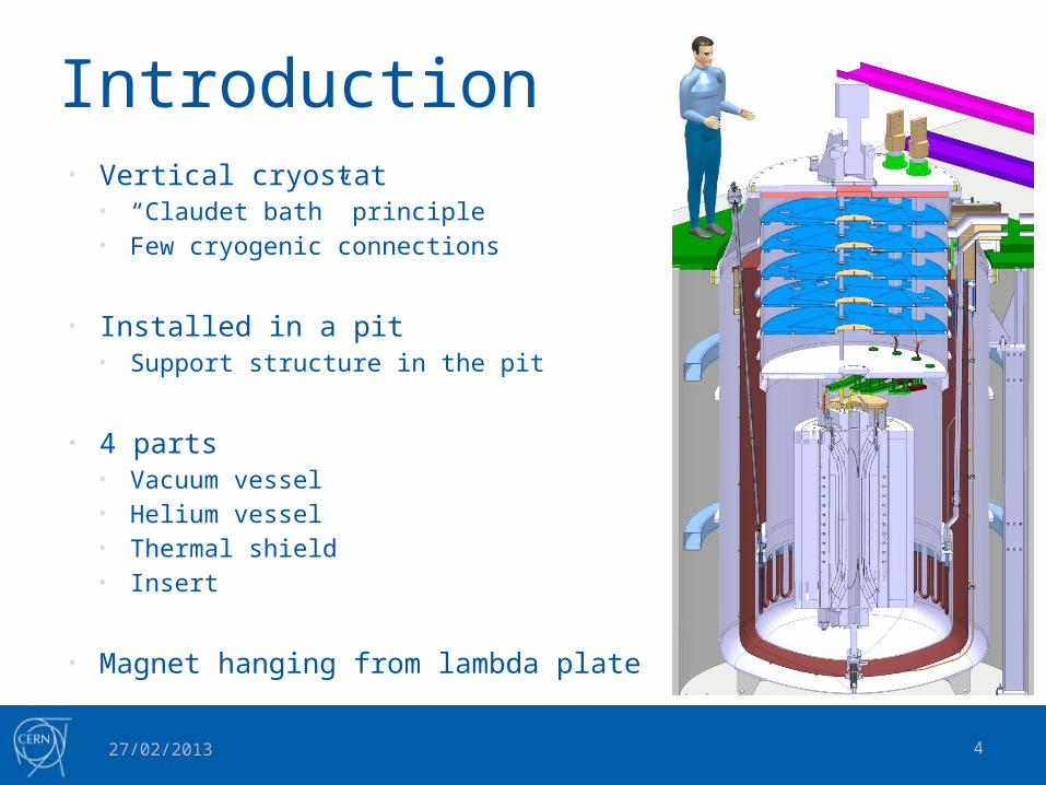
Introduction• Vertical cryostat
• “Claudet bath” principle• Few cryogenic connections
• Installed in a pit• Support structure in the pit
• 4 parts• Vacuum vessel• Helium vessel• Thermal shield• Insert
• Magnet hanging from lambda plate
27/02/2013
5
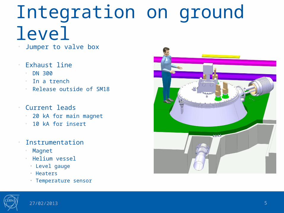
Integration on ground level• Jumper to valve box
• Exhaust line• DN 300• In a trench• Release outside of SM18
• Current leads• 20 kA for main magnet• 10 kA for insert
• Instrumentation• Magnet• Helium vessel
• Level gauge• Heaters• Temperature sensor
27/02/2013
6
Magnet cooling• 3 Phases
• 300 K – 80 K • 8 hours• Cold gaseous helium
• 80 K – 4.2 K• 8 hours• Liquid helium (1 bar)
• 4.2 K – 1.8 K• 36 hours (1.5 days)• Heat exchanger in cryostat
27/02/2013

7
Cooling from 300 K to 80 K
27/02/2013
Pre cooling valve box
Courtesy M. Bajko

8
Magnet cooling• 3 Phases
• 300 K – 80 K • 8 hours• Cold gaseous helium
• 80 K – 4.2 K• 8 hours• Liquid helium (1 bar)
• 4.2 K – 1.8 K• 36 hours (1.5 days)• Heat exchanger in cryostat
27/02/2013
9
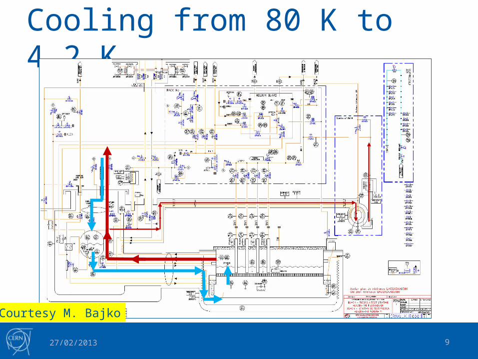
Cooling from 80 K to 4.2 K
27/02/2013
Courtesy M. Bajko
10
Magnet cooling• 3 Phases
• 300 K – 80 K • 8 hours• Cold gaseous helium
• 80 K – 4.2 K• 8 hours• Liquid helium (1 bar)
• 4.2 K – 1.8 K• 36 hours (1.5 days)• Heat exchanger in cryostat
27/02/2013

11
Cooling from 4.2 K to 1.8 K
27/02/2013
Heat in-leak estimation at 1.9KQnom=25W, Qdyn=40W, Qc-d=100W
LHe/LHe heat exchanger, 1.9KCooling power 100W,dT ≈30mK during cool down and dT≈10mK @ nominal condition
Pumping
Filling
LHe/GHe heat exchanger 1.9K Cooling power up to
150W at 2K
Courtesy M. Bajko
12
Design
27/02/2013
13
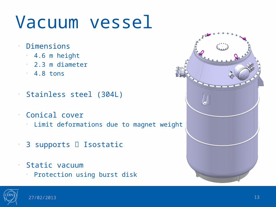
Vacuum vessel• Dimensions
• 4.6 m height• 2.3 m diameter• 4.8 tons
• Stainless steel (304L)
• Conical cover• Limit deformations due to magnet weight
• 3 supports Isostatic
• Static vacuum• Protection using burst disk
27/02/2013

14
Helium vessel• Max pressure : 5 bar
• Stainless steel (316 L, 316 LN)
• Welded to conical cover
• Neck thermalisation to limit heat in-leak
• Magnet support by lambda plate seat
• Heat exchanger for magnet cooling to 1.8 K
27/02/2013
1.9K
4.2K
300K

15
Helium vessel• Jumper
• Regroup all cryogenic lines• Connection to valve box
• Fixed point• Cryogenic lines• Block lines movement• G10 plate + Collars
27/02/2013
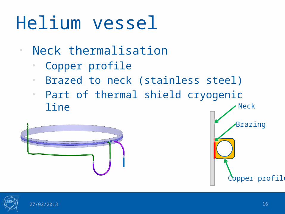
16
Helium vessel• Neck thermalisation
• Copper profile• Brazed to neck (stainless steel)• Part of thermal shield cryogenic line
27/02/2013
Neck
Brazing
Copper profile

17
Helium vessel• Heat exchanger
• Copper tube brazed to stainless steel tube
• U shaped and welded to flange (30 x)
• Saturated helium (18 mbar – 1.8 K) in the tubes
• Cool-down pressurized helium (magnet)
by conduction through copper
• Cooling power ≈ 100 W @ 1.9K
(1.5 day Cool-Down)
27/02/2013

18
Helium vessel• Heat exchanger prototype
27/02/2013
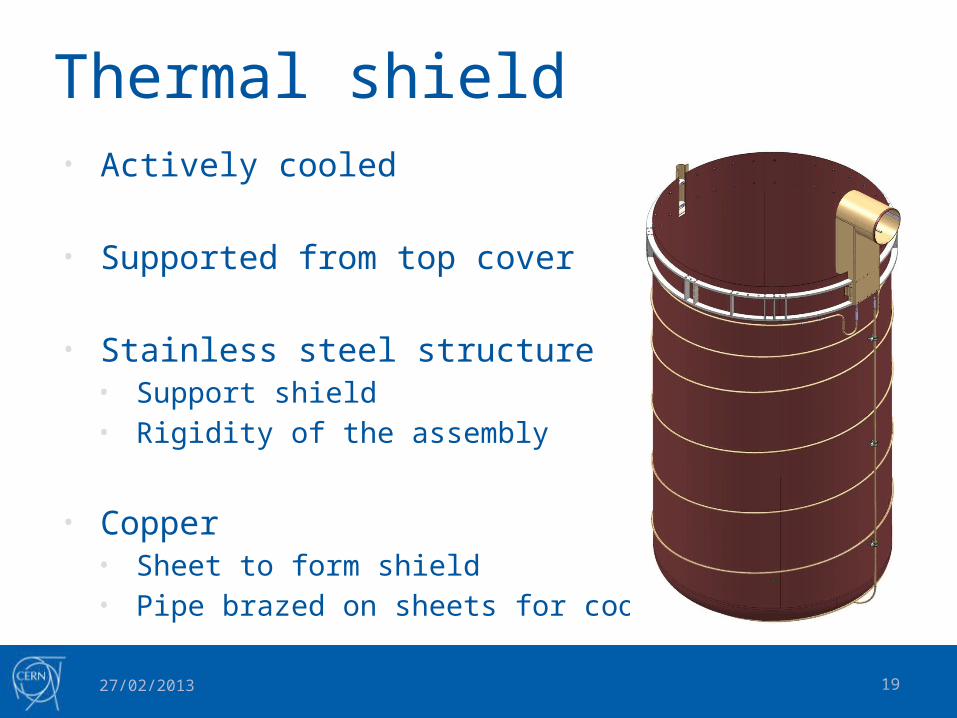
19
Thermal shield• Actively cooled
• Supported from top cover
• Stainless steel structure• Support shield• Rigidity of the assembly
• Copper• Sheet to form shield• Pipe brazed on sheets for cooling
27/02/2013

20
Insert (concept)• Top plate
• Current leads• Instrumentation
• Radiative screens
• Lambda plate• Quench valve (DN150)• Splices• Instrumentation
• Mechanical support• Lambda plate to top plate• Magnet (15 tons) to lambda plate
27/02/2013

21
Status
27/02/2013

22
Vacuum vessel
• Design : Finished
• Construction : In progress• First production meeting : 14th February 2013
• Delivery : June 2013
27/02/2013

23
Helium vessel• Design : Almost finished
• Call for tender : March 2013
• Order : Summer 2013
• Delivery : 6-7 months after order (Early 2014)
27/02/2013
24
Thermal shield and Insert• Thermal Shield
• Design in progress• Construction in the shadow of helium vessel
• Order expected for summer 2013
• Insert• Design in progress• Construction at CERN
27/02/2013

25
Conclusion
27/02/2013
26
Conclusion• Design almost finished
• Construction in progress• All components at CERN early 2014
• Assembly phase to be planned• Assembly of the cryostat• Connection to other components
27/02/2013

27
Acknowledgment• M. Bajko (TE-TF)• V. Benda (TE-CRG)• G. De Rijk (TE)• C. Giloux (TE-TF)• P. Minginette (EN-MME)• V. Parma (TE-MSC)• P. Perret (EN-MME)• P. Viret (TE-TF)• CERN TE-MSC-CMI Section
27/02/2013

28
Thank you for your attention !
27/02/2013
