armor materials research
TRANSCRIPT

Regular readers of the AMPTIAC Quarterly will have noticed thatwe’ve published several ‘special issues’ over the past few years. Thecommon aim of these publications has been to highlight topics ofspecial interest to targeted technological communities. Examplesinclude our issues on nanotechnology (May 2002) and blast mitiga-tion (Protecting People at Risk, February 2003). Both issues were well received by our readers but for different reasons: Nanotechnol-ogy represents an exciting andunexplored frontier with intense scientific interest; while protect-ing people and structures fromexplosions has gained national attention, especially since 9/11. This current issue addresses perhaps an even more important topic:the development of new technologies to enable our ground troopsto become more effective in the war against terror as well as otheremerging global threats.
All one has to do is follow the news reports to appreciate themajor technological hurdles now facing the Army. Gone are the days when we faced large standing armies, consisting of heavilyarmored units employing traditional tactics much like our own.Today, we face adversaries that seemingly have no qualms at sacrific-ing their lives or those of innocent bystanders in an attempt toinflict damage on our troops. Through a mix of conventional andunconventional weapons (such as improvised explosive devices or IEDs) these fanatics have forced us to adopt new tactics whilerelying upon our existing weaponry and equipment.
To be totally effective against our new and other possible futureenemies, the Army must transform from a force relying on heavyarmor to one employing a broad spectrum of lightweight, yet sur-vivable systems and equipment that will enhance their ability tofight. In this context, the word ‘transform’ means to change doc-trine, tactics, and assets to respond rapidly to the environments ofthe new battlefield. The challenge for our community is to developthe advanced materials that will provide the Army improved effec-tiveness across the full spectrum of operational environments. Tomake things even more complex, researchers must address addition-al 21st Century requirements beyond mere system performance.They must give greater consideration for ‘green’ solutions thatreduce the generation or introduction of toxic materials into theenvironment during production, training, deployment, or othermilitary operations.
Much recent work has been undertaken to improve the surviv-ability of vehicles and their occupants subjected to fire from ballis-tic weapons as well as blast and fragmentation from mines, Rock-et-Propelled Grenades (RPGs), and IEDs. Discussed in thispublication are several of the emerging materials that will enableimproved yet lighter armor for future systems. Included are ceram-ic, metal, and composite material research programs that show
tremendous promise. Pastarmor research has yielded theeffective but heavy systems weemploy today. Becoming more
effective against insurgents requires lighter armored vehiclesemploying innovative materials including transparent armor forwindshields and visors. Armor research has been and continues tobe a significant activity at the Army Research Laboratory.
Other subjects of significant interest are those related to ordnancematerials, including propellants, projectiles, and even the systemsused to shoot them. One area of concern lately has been to findreplacements for lead bullets and depleted uranium (DU) kineticenergy penetrators. Environmental concerns are the primary reasonsfor finding alternative materials for these applications, and several ofthe articles here discuss the programs addressing the problem.
One approach to reduce the weight and complexity of systems isto develop multifunctional materials that perform two or more pri-mary functions. Army researchers have many programs underwaythat are leading to technologies that exploit this concept and sever-al of them are mentioned here. A multitude of other technologydevelopment efforts are also being examined to develop the newgeneration of lighter, higher performance materials needed toimprove warfighting effectiveness.
The twenty separate articles contained in this issue of the AMPTIAC Quarterly will provide you with a glimpse at some of thetechnologies that will enable the Army to transform into a moremobile, survivable, and lethal force while simultaneously becominga better steward of the environment. There are numerous technicalchallenges yet to be overcome, but as the reader will notice the ArmyResearch Laboratory’s Weapons and Materials Research Directorate(ARL/WMRD) is actively pursing those technologies necessary forthe Army to transform the face of the new battlefield.
David H. Rose AMPTIAC Director
Editorial:Adapting to a Changing Battlefield
The AMPTIAC Quarterly is published by the Advanced Materials and Processes Technology Information AnalysisCenter (AMPTIAC). AMPTIAC is a DOD-sponsored Information Analysis Center, administratively managed bythe Defense Technical Information Center (DTIC). Policy oversight is provided by the Office of the Secretary ofDefense, Director of Defense Research and Engineering (DDR&E). The AMPTIAC Quarterly is distributed tomore than 15,000 materials professionals around the world.
Inquiries about AMPTIAC capabilities, products, and services may be addressed to David H. RoseDirector, AMPTIAC315-339-7023
E M A I L : a m p t i a c @ a l i o n s c i e n c e . c o mU R L : http :/ / a m p t i a c . a l i o n s c i e n c e . c o m
We welcome your input! To submit your related articles, photos, notices, or ideas for future issues, please contact:
AMPTIACATTN: CHRISTIAN E. GRETHLEIN201 Mill StreetRome, New York 13440
PHONE : 315 .339 .7009
FAX : 315 .339 .7107
E M A I L : a m p t i a c _ n ews @ a l i o n s c i e n c e . c o m
Editor-in-ChiefChristian E. Grethlein, P.E.
Creative Director Cynthia Long
Content EditorsRichard A. LaneBenjamin D. Craig
Information ProcessingJudy E. TallarinoPatricia McQuinn
Inquiry ServicesDavid J. Brumbaugh
Product SalesGina Nash

INTRODUCTIONThe US Army is undergoing a paradigm shift toward highlymobile, rapidly deployable, readily sustained units of action hav-ing unprecedented lethality and survivability. While currentground fighting vehicles have evolved to their 70+ ton status, inpart to defend against the ever-increasing lethality of ballisticthreats, their sheer mass and support requirements do not makethem easily transportable or readily sustainable. Therefore, asthe US Army transforms, future combat systems (FCS) willemploy lightweight, highly mobile, transportable, and lethalarmored vehicles that maintain the highest level of survivability.
To achieve armor performance exceeding that of the currentcombat vehicles for new vehicular systems weighing less than20 tons, significant advances in survivability technology arerequired. Advanced materials and their multifunctional inte-gration are critical to the successful design of new light armors.One such light armor solution being developed is an advancedcomposite armor that combines ceramics, metals, and polymer-ic composites to provide unmatched mass efficient protection.Such rapid advancements are only possible with similar devel-opments in individual materials and modeling technology. Asceramics and metals are the focus of other articles in this issue,this paper will first highlight the evolution of ‘the plastic tank’and then detail the recent advancements in organic materialstechnology and advanced simulation capability for applicationof composites in vehicle armor.
THE ‘PLASTIC TANK’ - A HISTORY OF COMPOSITE STRUCTURAL ARMORComposite armor systems are not new. During the pioneeringlight armor experiments against small arms threats conducted inthe late 1960’s, Wilkins and co-workers [1-3] determined that
hard ceramics coupled with a thin ductile backing form effec-tive, mass efficient armor systems. These researchers recognizedthat ceramics possess characteristics such as low density, highhardness, and high compressive strength; all of which were well-suited for light armor systems. When coupled with compositematerials having superior strength-to-weight and stiffness-to-weight properties, ceramic/composite armor provides mass effi-cient ballistic protection against a number of threats. Integratingthese materials as a mass efficient armor system on armoredvehicles has been reported in the open literature since the 1980’s[4], and the US Army’s efforts in the development and applica-tion of composite armor during this time are detailed below.
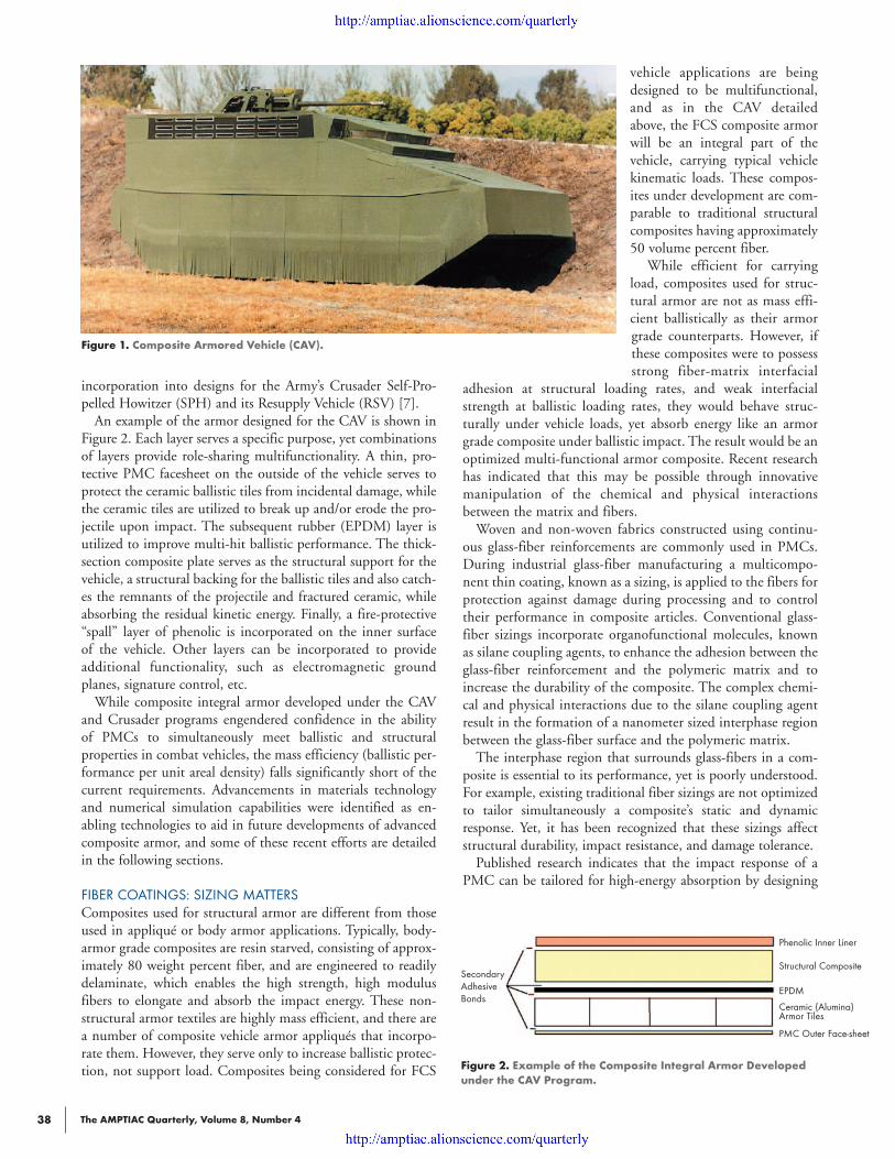
Through several key R&D programs during the 1980’s and1990’s, the Army established a confidence-building baseline forthe application of polymer matrix composites (PMCs) to light-en heavy forces while also improving survivability for lightforces. The first application of thick-section PMCs to armoredvehicles was in a demonstration program in the late 1980’sunder which a polyester/glass composite hull was developed toreplace the aluminum hull on the Bradley Infantry FightingVehicle (BIFV). The resulting vehicle, with a thick-sectioncomposite hull and appliqué ceramic armor tiles, becameknown as the Composite Infantry Fighting Vehicle (CIFV) anddemonstrated the ability of PMCs to perform well structurallyin an armored vehicle [5]. This vehicle was followed by theComposite Armored Vehicle (CAV) program; established toassess the application of PMCs in the ground-up design of anarmored vehicle [6]. To meet the stringent weight and ballisticperformance requirements of the CAV, which is shown in Fig-ure 1, the concept of a multifunctional PMC-based armor wasdeveloped. The resulting composite integral armor (CIA) per-formed exceptionally well and was subsequently adapted for
Bryan A. CheesemanRobert Jensen
Christopher HoppelWeapons and Materials Research Directorate
US Army Research LaboratoryAberdeen Proving Ground, MD
The AMPTIAC Quarterly, Volume 8, Number 4 37
The AMPTIAC Quarterly, Volume 8, Number 438
incorporation into designs for the Army’s Crusader Self-Pro-pelled Howitzer (SPH) and its Resupply Vehicle (RSV) [7].
An example of the armor designed for the CAV is shown inFigure 2. Each layer serves a specific purpose, yet combinationsof layers provide role-sharing multifunctionality. A thin, pro-tective PMC facesheet on the outside of the vehicle serves toprotect the ceramic ballistic tiles from incidental damage, whilethe ceramic tiles are utilized to break up and/or erode the pro-jectile upon impact. The subsequent rubber (EPDM) layer isutilized to improve multi-hit ballistic performance. The thick-section composite plate serves as the structural support for thevehicle, a structural backing for the ballistic tiles and also catch-es the remnants of the projectile and fractured ceramic, whileabsorbing the residual kinetic energy. Finally, a fire-protective“spall” layer of phenolic is incorporated on the inner surface of the vehicle. Other layers can be incorporated to provideadditional functionality, such as electromagnetic groundplanes, signature control, etc.
While composite integral armor developed under the CAVand Crusader programs engendered confidence in the ability of PMCs to simultaneously meet ballistic and structural properties in combat vehicles, the mass efficiency (ballistic per-formance per unit areal density) falls significantly short of thecurrent requirements. Advancements in materials technologyand numerical simulation capabilities were identified as en-abling technologies to aid in future developments of advancedcomposite armor, and some of these recent efforts are detailedin the following sections.
FIBER COATINGS: SIZING MATTERSComposites used for structural armor are different from thoseused in appliqué or body armor applications. Typically, body-armor grade composites are resin starved, consisting of approx-imately 80 weight percent fiber, and are engineered to readilydelaminate, which enables the high strength, high modulusfibers to elongate and absorb the impact energy. These non-structural armor textiles are highly mass efficient, and there area number of composite vehicle armor appliqués that incorpo-rate them. However, they serve only to increase ballistic protec-tion, not support load. Composites being considered for FCS
vehicle applications are beingdesigned to be multifunctional,and as in the CAV detailedabove, the FCS composite armorwill be an integral part of thevehicle, carrying typical vehiclekinematic loads. These compos-ites under development are com-parable to traditional structuralcomposites having approximately50 volume percent fiber.
While efficient for carryingload, composites used for struc-tural armor are not as mass effi-cient ballistically as their armorgrade counterparts. However, ifthese composites were to possessstrong fiber-matrix interfacial
adhesion at structural loading rates, and weak interfacialstrength at ballistic loading rates, they would behave struc-turally under vehicle loads, yet absorb energy like an armorgrade composite under ballistic impact. The result would be anoptimized multi-functional armor composite. Recent researchhas indicated that this may be possible through innovativemanipulation of the chemical and physical interactionsbetween the matrix and fibers.
Woven and non-woven fabrics constructed using continu-ous glass-fiber reinforcements are commonly used in PMCs.During industrial glass-fiber manufacturing a multicompo-nent thin coating, known as a sizing, is applied to the fibers forprotection against damage during processing and to controltheir performance in composite articles. Conventional glass-fiber sizings incorporate organofunctional molecules, knownas silane coupling agents, to enhance the adhesion between theglass-fiber reinforcement and the polymeric matrix and toincrease the durability of the composite. The complex chemi-cal and physical interactions due to the silane coupling agentresult in the formation of a nanometer sized interphase regionbetween the glass-fiber surface and the polymeric matrix.
The interphase region that surrounds glass-fibers in a com-posite is essential to its performance, yet is poorly understood.For example, existing traditional fiber sizings are not optimizedto tailor simultaneously a composite’s static and dynamicresponse. Yet, it has been recognized that these sizings affectstructural durability, impact resistance, and damage tolerance.
Published research indicates that the impact response of aPMC can be tailored for high-energy absorption by designing
Figure 1. Composite Armored Vehicle (CAV).
Figure 2. Example of the Composite Integral Armor Developedunder the CAV Program.
Phenolic Inner Liner
Structural Composite
EPDM
Ceramic (Alumina)Armor Tiles
PMC Outer Face-sheet
SecondaryAdhesiveBonds

The AMPTIAC Quarterly, Volume 8, Number 4 39
weak fiber-matrix interfacial interactions. Conversely, structur-al performance (strength) is achieved by strong fiber-matrixinterfacial interactions. Hence, the aforementioned trade-offsexist. Although the achievement of simultaneous high strengthand energy absorption levels is desirable, the technology hasnot been available. New approaches are now available to over-come these traditional materials shortcomings.
The glass-fiber sizing research being performed at ARL hassystematically examined the nature of the glass-fiber/ther-mosetting polymer interphase region to develop the fundamen-tal understanding necessary to propose and validate an entirelynew class of sizing materials. Specifically, mixed organofunc-tional silane coupling agents are being employed to vary thechemical reactivity toward the polymeric matrix phase to pro-duce bond strengths that are dependent on the viscoelasticproperties of the matrix and fiber-coating. This results in aninherent “viscoelastic switch” at the fiber-matrix interphase thatyields strong fiber-matrix interactions (high structural strength)at low strain rates and weak fiber-matrix interactions (ballisticperformance) at high strain rates. This triggered response iscoupled with the application of inorganic-organic sol-gelprocesses to develop silane-based, glass-fiber sizings thatincrease the surface roughness of commercially produced glassfibers. The result is an increased coefficient of friction betweenthe fiber and matrix during the fiber pullout stages of compos-ite failure, further resulting in enhanced energy absorption inthe composite during ballistic events. These results were firstdocumented mechanically on micro-scale model compositespecimens. Subsequently, the experimental inorganic-organichybrid fiber sizings were scaled-up and applied using commer-cial manufacturing equipment to demonstrate their behavior inmacroscale composite materials.
Figure 3 shows the successful nano-texturing of the fibersurfaces produced on a commercial scale using atomic forcemicroscopy (AFM). Glass reinforced composite materials weremanufactured using these specialized fabrics, and the structur-al and impact energy responses were measured. Figure 4 cap-tures the impact energy absorption and structural performanceof composites produced using state-of-the-art commercial siz-ings and the ARL inorganic-organic hybrid sizings. Theseresults show the traditional trade-offs found when using com-mercially available fibers that have been coated with either astructural or ballistic sizing. In comparison, these trade-offs donot exist for the ARL inorganic-organic hybrid sizing, and theimpact and structural performance of this optimized sizing areboth excellent. A 40% increase in the energy absorption ofcomposites fabricated with no loss in structural properties will
enable the use of PMCs in ballistic applications where theyhave not been used previously, perhaps with reduced cost.
ADVANCES IN MODELING: ROBUST COMPOSITE MATERIAL MODEL FOR IMPACT AND BLASTLess than ten years ago, a review paper on the state-of-the-artin numerical modeling of high-velocity impact stated thatthere was no definitive computational model for ceramics andthat high velocity impact calculations of fiber-reinforced com-posites were a research task [8]. These limitations in numericaltechniques and robust material models resulted in much of thedesign of composite armor systems being guided by experi-mental efforts. However, since then the advances in numericaltechniques and development of robust material models haveallowed modelers to simulate accurately what is observedexperimentally, and this has allowed greater insight into howthe components of the composite armor work together duringthe impact event. These recent developments have allowedexperiments and simulations to be utilized together to improvethe performance of composite armor for FCS.
MODELING COMPOSITE ARMORAccuracy in modeling of ceramics has been aided by the use ofLaGrangian particle techniques, either smooth particle hydro-dynamics (SPH) or general particle algorithms (GPA), which,when coupled with a validated material model, have given verygood correlation with experimental observations of impact into
Figure 3. Surface AFM Images of Standard Commercial Fiber (Left) in Comparison to ARL Nano-RoughenedCommercially Produced Fiber (Right).
Figure 4. Mechanical Performance of Composites with VariousSizings. The ARL Sizing Shows Exceptional Performance in bothEnergy Absorption (Shown in Green) and Compressive Strength(Shown in Orange).
“Structural” ARL Hybrid “Ballistic”Fiber Sizing Fiber Sizing Fiber Sizing
120
100
80
60
40
20
0
160
140
120
100
80
60
40
20
0
Ener
gy A
bsor
ptio
n M
ax L
oad
(J)
Com
pres
sive
Stre
ngth
(MPa
)
The AMPTIAC Quarterly, Volume 8, Number 440
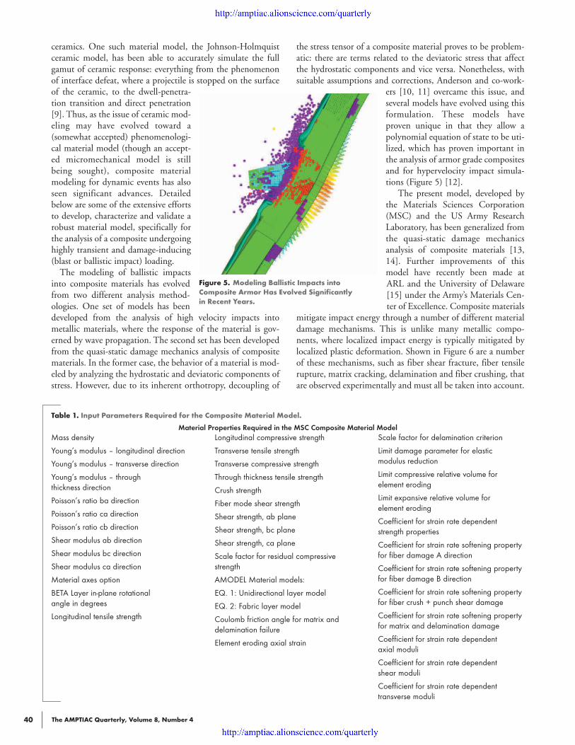
ceramics. One such material model, the Johnson-Holmquistceramic model, has been able to accurately simulate the fullgamut of ceramic response: everything from the phenomenonof interface defeat, where a projectile is stopped on the surfaceof the ceramic, to the dwell-penetra-tion transition and direct penetration[9]. Thus, as the issue of ceramic mod-eling may have evolved toward a(somewhat accepted) phenomenologi-cal material model (though an accept-ed micromechanical model is stillbeing sought), composite materialmodeling for dynamic events has alsoseen significant advances. Detailedbelow are some of the extensive effortsto develop, characterize and validate arobust material model, specifically forthe analysis of a composite undergoinghighly transient and damage-inducing(blast or ballistic impact) loading.
The modeling of ballistic impactsinto composite materials has evolvedfrom two different analysis method-ologies. One set of models has beendeveloped from the analysis of high velocity impacts intometallic materials, where the response of the material is gov-erned by wave propagation. The second set has been developedfrom the quasi-static damage mechanics analysis of compositematerials. In the former case, the behavior of a material is mod-eled by analyzing the hydrostatic and deviatoric components ofstress. However, due to its inherent orthotropy, decoupling of
the stress tensor of a composite material proves to be problem-atic: there are terms related to the deviatoric stress that affectthe hydrostatic components and vice versa. Nonetheless, withsuitable assumptions and corrections, Anderson and co-work-
ers [10, 11] overcame this issue, andseveral models have evolved using thisformulation. These models haveproven unique in that they allow apolynomial equation of state to be uti-lized, which has proven important inthe analysis of armor grade compositesand for hypervelocity impact simula-tions (Figure 5) [12].
The present model, developed bythe Materials Sciences Corporation(MSC) and the US Army ResearchLaboratory, has been generalized fromthe quasi-static damage mechanicsanalysis of composite materials [13,14]. Further improvements of thismodel have recently been made atARL and the University of Delaware[15] under the Army’s Materials Cen-ter of Excellence. Composite materials
mitigate impact energy through a number of different materialdamage mechanisms. This is unlike many metallic compo-nents, where localized impact energy is typically mitigated bylocalized plastic deformation. Shown in Figure 6 are a numberof these mechanisms, such as fiber shear fracture, fiber tensilerupture, matrix cracking, delamination and fiber crushing, thatare observed experimentally and must all be taken into account.
Figure 5. Modeling Ballistic Impacts into Composite Armor Has Evolved Significantly in Recent Years.
Table 1. Input Parameters Required for the Composite Material Model.
Material Properties Required in the MSC Composite Material ModelMass density
Young’s modulus – longitudinal direction
Young’s modulus – transverse direction
Young’s modulus – through thickness direction
Poisson’s ratio ba direction
Poisson’s ratio ca direction
Poisson’s ratio cb direction
Shear modulus ab direction
Shear modulus bc direction
Shear modulus ca direction
Material axes option
BETA Layer in-plane rotational angle in degrees
Longitudinal tensile strength
Longitudinal compressive strength
Transverse tensile strength
Transverse compressive strength
Through thickness tensile strength
Crush strength
Fiber mode shear strength
Shear strength, ab plane
Shear strength, bc plane
Shear strength, ca plane
Scale factor for residual compressivestrength
AMODEL Material models:
EQ. 1: Unidirectional layer model
EQ. 2: Fabric layer model
Coulomb friction angle for matrix anddelamination failure
Element eroding axial strain
Scale factor for delamination criterion
Limit damage parameter for elastic modulus reduction
Limit compressive relative volume for element eroding
Limit expansive relative volume for element eroding
Coefficient for strain rate dependentstrength properties
Coefficient for strain rate softening propertyfor fiber damage A direction
Coefficient for strain rate softening propertyfor fiber damage B direction
Coefficient for strain rate softening propertyfor fiber crush + punch shear damage
Coefficient for strain rate softening propertyfor matrix and delamination damage
Coefficient for strain rate dependent axial moduli
Coefficient for strain rate dependent shear moduli
Coefficient for strain rate dependent transverse moduli
The AMPTIAC Quarterly, Volume 8, Number 4 41
Generally, in composite damage mechanics models, materialdamage and failure are accounted for only by a resultantdecrease in the material stiffness in the corresponding materialdirections. The current model utilizes this concept, but alsoaccounts for the inter-relations of the different failure modesthrough quadratic failure criteria and a novel damage tensorthat relates the specific failure modes to the extensional andshear moduli that are compromised. The formulation is basedon the continuum damage model for composite failure devel-oped by Matzenmiller et al. [16] and has been extended toincorporate strain rate sensitivity of both stiffness and strengthand post failed material softening.
While the details of this elegant and complex material modelare beyond the scope of the current article (for further details,refer to [13]), it is not surprising that there are a number of
material constants that must be determined in order togenerate accurate simulations. Table 1 shows a list of theconstants required by the composite damage model,which has been incorporated into the commercialdynamic finite element analysis software LS-DYNA,where it is known as MAT 161/162. Obviously, in orderto perform accurate simulations of a composite materialusing the current model, a substantial material character-ization program is required. As part of the CompositeMaterial Technology (CMT) program, the Center forComposite Materials (CCM) at the University ofDelaware has been working with ARL and MSC to fullycharacterize materials of interest and validate these valuesby performing simulations of the experiments using LS-DYNA and the current material model.
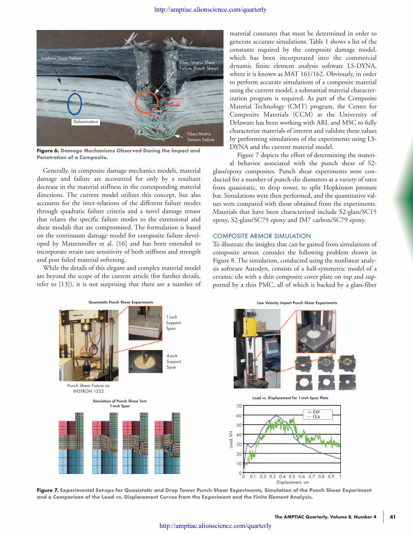
Figure 7 depicts the effort of determining the materi-al behavior associated with the punch shear of S2-
glass/epoxy composites. Punch shear experiments were con-ducted for a number of punch-die diameters at a variety of ratesfrom quasistatic, to drop tower, to split Hopkinson pressurebar. Simulations were then performed, and the quantitative val-ues were compared with those obtained from the experiments.Materials that have been characterized include S2-glass/SC15epoxy, S2-glass/SC79 epoxy and IM7 carbon/SC79 epoxy.
COMPOSITE ARMOR SIMULATIONTo illustrate the insights that can be gained from simulations ofcomposite armor, consider the following problem shown inFigure 8. The simulation, conducted using the nonlinear analy-sis software Autodyn, consists of a half-symmetric model of aceramic tile with a thin composite cover plate on top and sup-ported by a thin PMC, all of which is backed by a glass-fiber
Figure 6. Damage Mechanisms Observed During the Impact and Penetration of a Composite.
Figure 7. Experimental Set-ups for Quasistatic and Drop Tower Punch Shear Experiments, Simulation of the Punch Shear Experimentand a Comparison of the Load vs. Displacement Curves from the Experiment and the Finite Element Analysis.
In-plane Shear Failure
Delamination
Fiber/Matrix ShearFailure (Punch Shear)
Fiber/MatrixTension Failure
Crush
1-inchSupportSpan
Punch Shear Fixture onINSTRON 1332
Simulation of Punch Shear Test:1-inch Span
Quasistatic Punch Shear Experiments Low Velocity Impact Punch Shear Experiments
Load vs. Displacement for 1-inch Span Plate
4-inchSupportSpan
0 0.1 0.2 0.3 0.4 0.5 0.6 0.7 0.8 0.9 1Displacement, cm
70
60
50
40
30
20
10
0
EXPFEA
Load
, kN

The AMPTIAC Quarterly, Volume 8, Number 442
PMC. In the impact region, all of the materials are modeledusing smooth particle hydrodynamics (SPH). The tile itself issurrounded and confined by steel brackets modeled usingLaGrangian elements.
As a measure of how the composite armor reacts uponimpact, the deceleration of a target point on the rear surface ofthe fragment-simulating projectile (FSP) is tracked during theimpact event. The deceleration of the FSP for this baseline caseis given in Figure 9. From this figure, it can be seen that thedeceleration curve of the FSP has three distinct portions: aninitial steep deceleration up to approximately 35 µs, a transi-tion region from roughly 35-45 µs, and a final, more moderatedeceleration curve from 45-90 µs.
By observing the plots of the material damage through time,an understanding of the mechanisms behind these regionsbecomes discernible. The initial rapid deceleration is caused bythe hard ceramic deforming the FSP. During this time, theceramic itself fails, its failure starting on the surface oppositethe impact surface due to the tensile reflections from the initialcompressive stress wave. In Figure 9, green regions indicateundamaged material, and colored regions indicate material thatis either plastically deformed or damaged. The cyan color of theprojectile indicates that it is plastically deforming. For the com-posite, the cyan and orange coloring indicates transverse sheardamage, the purple indicates in-plane tensile failure and for allmaterials, red indicates bulk failure. The cracking of the ceram-ic leads to the formation of a conoid (a cone of ceramic mate-rial under the impactor) which loads the backing plates.
Extensive transverse shear damage mechanisms appear in allof the composites by 20 µs. The initial deceleration of the pro-jectile transitions to a more moderate deceleration of the pro-jectile at approximately 30 µs, and it is at this time that thedamaged composites have displaced enough locally to allow thefailed ceramic in the conoid to start moving, both in the direc-tion of the projectile and laterally, out of the way of the projec-tile. The effectiveness of the ceramic diminishes greatly from 30µs to 45 µs. After 45 µs, the damaged glass/epoxy compositecatches both the ceramic rubble and the plastically deformedprojectile.
SUMMARYThe application of polymer-matrix composite materials toarmor systems has principally been driven by the need toincrease performance (survivability) in very lightweight fight-ing vehicles. The stringent weight requirements for these typesof applications have provided the motivation for the develop-ment of multi-functional armor systems. Ceramic-compositearmor systems have been developed to provide ballistic protec-tion from a range of battlefield threats and also serve as thevehicle structure.
Substantial progress has been made in the development ofmaterials technology for lightweight fighting vehicles, includ-ing advances in fiber sizings that have been formulated to pro-vide strain-rate sensitive response (strong fiber-matrix interfa-cial adhesion at structural loading rates, and weak interfacialstrength at ballistic loading rates). Additionally, the develop-ment, characterization and validation of improved materialconstitutive models have allowed ballistic experiments to bestudied using numerical simulations, which have provided newinsight into how the materials behave and interact duringimpact. Further advances in materials technology and theirincorporation into lightweight armor will focus on theincreased integration of multifunctionality, such as the incor-poration of power storage, communication, sensing, and healthmonitoring, which are described elsewhere in this issue of theAMPTIAC Quarterly. Numerical simulations will allow engi-neers to examine the influence of multifunctional materials onimproving the performance of ceramic composite armor thatwill be utilized in future combat systems.
REFERENCES[1] M.L. Wilkins, Second Progress Report of the Light Armor Pro-gram, Lawrence Livermore National Laboratory, Livermore,CA, Technical Report No. UCRL 50284, 1967[2] M.L. Wilkins, Third Progress Report of the Light Armor Pro-gram, Lawrence Livermore National Laboratory, Livermore,CA, Technical Report No. UCRL 50349, 1968[3] M.L. Wilkins, C.F. Cline, and C.A. Honodel, FourthProgress Report of the Light Armor Program, Lawrence Livermore
Figure 8. Model Used for the Numerical Simulation of aComposite Armor System.
Figure 9. Projectile Velocity as a Function of Time for theBaseline Configuration.
Steel Projectile (SPH) Composite TileSupport Layer
CompositeCoverSteel
Surrounds
Glass Composite Backing
0 0.02 0.04 0.06 0.08 0.1Time (ms)
FSP
Velo
city
(m/s
)
1000
800
600
400
200
0
SPH
LaGrangeElements
Ceramic
I
II III
FSP Velocity vs. Time for Ceramic Backed by Carbon Fiber Composite Configuration
The AMPTIAC Quarterly, Volume 8, Number 4 43
National Laboratory, Livermore, CA, Technical Report No.50694, 1969[4] R.M. Ogorkiewicz, Armored Vehicles of Composite Materials,International Defence Review, July 1989[5] G. Thomas, A. Larson, and J. Garces, Composite Hull Program Final Technical Report, Army Research LaboratoryContractor Report No. ARL-CR-179, December 1994[6] T. Pike, M. McArthur, and D. Schade, Vacuum-AssistedResin Transfer Molding of a Layered Structural Laminate forApplication on Ground Combat Vehicles, Proceedings of the 28thInternational SAMPE Technical Conference, Seattle, WA, pp.374-380, November 4-7, 1996[7] B.K. Fink, Performance Metrics for Composite Integral Armor,Journal of Thermoplastic Composite Materials, Vol. 13, No. 5,pp. 417-431, September 2000[8] J.A. Zukas, Numerical Modeling of High Velocity Impact inNon-Metallic Materials, Vol. 48, High Strain Rate Effects onPolymer, Metal and Ceramic Matrix Composites and OtherAdvanced Materials, ASME, New York NY, 1995[9] T.J. Holmquist and G.R. Johnson, Response of Silicon Carbide to High Velocity Impact, Journal of Applied Physics,91(9), pp. 5858-5866, 2002[10] P.E. O’Donoghue, C.E. Anderson, Jr., G.J. Friesenhahn,and C.H. Parr, A Constitutive Formulation for Anisotropic
Materials Suitable for Wave Propagation Computer Programs,J.Comp. Materials, pp. 26(13), pp. 1860-1884, 1992[11] C.E. Anderson, Jr., P.A. Cox, G.R. Johnson, and P.J.Maudlin, A Constitutive Formulation for Anisotropic MaterialsSuitable for Wave-Propagation Computer Programs 2, Computa-tional Mechanics, 15(3), pp. 201-223, 1994.[12] W. Riedel, W. Harwick, D.M. White, and R.A. Clegg,ADAMMO Advanced Material Damage Models for NumericalSimulation Codes, EMI Report No. 175/03, Freiburg Germany,October 31 2003[13] C.F. Yen, Ballistic Impact Modeling of Composite Materials,Proceedings of the 7th International LS-DYNA Users Confer-ence, Dearborn MI, May 19-21, 2002[14] C.F. Yen, and A.A. Caiazzo, Design Methodology and Validation for Multifunctional Composite Armor, MSC Technical Progress Report, US Army Research Laboratory,Contract No. DAAD17-01-C-0111, July 2002[15] C.F. Yen, B.A. Cheeseman, C.P.R. Hoppel, B.A. Gama,and J.W. Gillespie, Modeling of the Compressive Failure of PlainWeave Composites, ASC/ASTM-D30 Joint 19th Annual Tech-nical Conference, Atlanta Georgia, October 17-20, 2004[16] A. Matzenmiller, J. Lubliner, and R.I. Taylor, A Constitu-tive Model for Anisotropic Damage in Fiber-Composites,Mechanics of Materials, 20, pp. 125-152, 1995
Dr. Christopher Hoppel leads the Kinetic Energy Defeat Team in the US Army Research Laboratory. He overseesthe development of structural armor for the Army’s Future Combat Systems. He serves on the executive committeeof the American Society of Composites and Leads the joint DOD/DOE TCG XII program (Advanced CompositeMaterials for Munitions). Dr. Hoppel earned his BS, ME, and PhD in Engineering Science and Mechanics fromPennsylvania State University.
Dr. Robert Jensen is a Research Chemist in the Engineering Materials Team of the Multifunctional Materials Branch,at the US Army Research Laboratory, Aberdeen Proving Ground, MD. Dr. Jensen’s research involves the develop-ment of novel sol-gel based fiber sizings for energy absorption in composite materials as well as the investigationof surface and adhesion phenomena. Dr. Jensen holds a BS in Chemistry from Francis Marion University; and a PhDin Physical Chemistry from Virginia Tech, specializing in structure-property relationships in polymeric materials.
Dr. Bryan A. Cheeseman is a mechanical engineer in the Survivability Materials Branch of the US Army ResearchLaboratory’s Weapons & Materials Research Directorate. He leads numerical simulation efforts investigating ballistic impact into fabrics, composites, and lightweight composite armor. In addition, he also conducts coupledEulerian-LaGrangian blast-structure interaction simulations. Dr. Cheeseman earned his BS, MS, and PhD inMechanical Engineering from the University of Delaware.