arm: microcontroller touch-switch design & test (part 1) - imperial
TRANSCRIPT

ARM: Microcontroller Touch-switch Design & Test (Part 1)
2nd Year Electronics Lab
IMPERIAL COLLEGE LONDON
v2.00

2
Table of Contents
Equipment ............................................................ 2
Aims ........................................................................ 2
Objectives ............................................................. 2
Recommended Timetable ............................... 2
Introduction – Capacitive touch-switch
principle of operation ...................................... 2
Sessions 1 & 2 – Hardware & PCB Design .. 3
Sessions 3 & 4 – Software ................................ 4
Counting Loop Basics ............................................ 5 Software Implementation and Testing .......... 5 Further Optimization (Optional) ..................... 7
Further Information ......................................... 8
Equipment mbed module
mbed account (one per student)
LPCxpresso Base Board for mbed with
OLED display
Breadboard and IDC breakout adaptor
Signal generator (for 0V 3V square
wave output)
Oscilloscope (to check signal generator
output)
EAGLE v5 CAD software (freeware
version)
Aims In this experiment and its continuation (SWITCH
next term), you will design, build and test a touch-
switch input device used with a high-performance
ARM processor. You will learn:
How to implement embedded systems
with appropriate use of high level
languages
How to design, build and test simple PCBs
Objectives 1. Design hardware PCB for touch-switch
2. Become familiar with the mbed
embedded programming environment
3. Write and test code for software
implementation of one or more capacitive
touch-switches via measurement of
frequency on the microcontroller input
pins. All software can be implemented in
C++, a high-level programming language.
4. Next term, your PCBs will return from the
manufacturer. In the SWITCH experiment,
you will build and test hardware, choose
component values, integrate and test the
complete system by developing the
software further.
This experiment links to the programming
exercise in Introduction to Computer Architecture
course (EE2-19), which uses a low-level
assembler solution to this problem. The code
written for ARM in this experiment is expected to
be high-level, you do not have enough time to
write an assembler solution.
Recommended Timetable Session 1 – PCB tutorial, working through
a simple sample design followed by the
start of your (real) PCB design according
to specifications provided in this handout.
Session 2 – Finish the real PCB design.
Check for correctness. Submit for
assessment
Session 3 – Familiarization with mbed
environment. Write code to measure
frequency on one input. Measure
performance.
Session 4 – Code software for multiple
inputs. Measure performance. If time
allows, experiment with optimizations.
Introduction – Capacitive touch-switch
principle of operation A resistor R and capacitor C, combined with a
logic inverter, forms a Schmidt Trigger oscillator
with output frequency dependent on values of R
and C. The capacitor is formed from the parallel
combination of a fixed capacitor and a touch-pad
as shown in Figure 1. The effective capacitance of
the touch-pad increases when a finger is brought
close, reducing the output frequency.

3
If the output frequency is measured and
compared with a fixed threshold frequency, this
will give a touch/no touch indication.
The system may have some noise, but using two
thresholds for the output frequency, as shown in
Figure 2, is an effective method to reduce noise.
Figure 1 - Circuit for a single touch-switch
Figure 2 - Frequency Waveform
A number of hardware circuits could be used to
measure frequencies; we will explore the simplest
and most flexible method. The digital oscillator
output is connected to a microcontroller input
port and software is used to count the number of
signal transitions, measure frequency and
perform thresholding. In a typical application of
this, the microcontroller would have many other
functions too, so the incremental cost of the
touch-switch circuit is only that of the oscillators.
Sessions 1 & 2 – Hardware & PCB Design In this section you will design a PCB, which
contains touch-pads, oscillators and an output via
a connector (Figure 3) to the microcontroller
board. The supply comes from the microcontroller
(+3.3V) via the connector.
You will be using EAGLE PCB software to design
the touch-switch PCB with the given EAGLE
library arm-parts.lbr, which has suitable
components for resistors, capacitors, touch-switch
pads, hex logic inverters and the connector. If you
wish to experiment with this at home, EAGLE can
be downloaded to your own PCs from the web
free of charge as a demo version.
NOTE: The latest EAGLE version (v6) will not be compatible with the ARM experiment, so you musn’t use it. This may also be the default version on the EEE system.
IDC socket mbed pin Port.Bit 1 GND 2 +3.3V 3 GND 4 +3.3V 5 NC 6 p30 p30 P0.4 7 NC 8 p29 p29 P0.5 9 p27 p27 P0.11
10 p28 p28 P0.10 11 NC 12 p11 p11 P0.18 13 NC 14 NC
NC = must be kept open circuit Figure 3 - 14pin IDC socket pinouts. A ribbon cable will
connect this to the LPCxpresso Base Board.
In order to complete your PCB design, you should
refer to the Specification for PCB on the ARM
handout web page.
List of actions for this task:
1. Work through the introductory EAGLE
tutorial (see ARM handout web page). The
questions (Q) in this are designed to help
you understand PCB design issues.
2. Enter a schematic (circuit diagram) using
components from the arm-parts library
(from the EAGLE PCB files on the ARM
handout web page) to construct 4 touch
switches (Figure 1) and connect each
touch-switch to a separate microcontroller
I/O port via a single 14-pin IDC socket
(Figure 3). You have some choice of
packages, the IC must be 74HC14 and the
capacitor can be small or large. Vcc for the
74HC14 IC should connect to the +3.3V pin
from the connector.
3. Check schematic consistency using ERC.
4
4. Check the PCB board specifications on the
ARM handout web page. These include
important board layout requirements.
Follow these requirements carefully. Ask a
demonstrator if there is anything you do
not understand.
5. Convert the schematic to a board. Change
the size of the board outline to that
specified by moving the top and RHS
edges. Clicking the middle of each edge
will move it as a whole. Check the
horizontal (X) and vertical (Y) dimensions
using statistics-brd.ulp before you start
placing components, since changing these
later will be troublesome.
6. Arrange components within the PCB
boundary. Add your lab group name
(important), PAD names on the layout and
any other text you wish.
7. Use auto-route to make PCB tracks. If you
do not get 100% optimization, or if the
layout is non-optimal, you may need to
rearrange the components. See the box
Routing Constraints below for instructions
on optimal routing.
Routing Constraints
PCBs can induce electromagnetic interference between adjacent tracks. In this circuit the only problem you will meet is the inverter inputs, which are high impedance nodes and can pick up interference. Specifically they can pick up interference from fast edges on other inverter outputs. The effect of this can be to lock oscillator frequencies together. To avoid this problem, ensure you inspect all tracks connected to each inverter input and check that it does not run adjacent and parallel to the tracks connected to an inverter output for more than 5mm.
8. Add testpoints and connections so that
you can test the board before you connect
them to the microcontroller. It will be
useful to have testpoints connected to
GND and Vcc. Reroute connections as
necessary.
9. Check board consistency with DRC.
10. Do one final check of the board
specifications, as well as a DRC check.
Submit board for manufacture via the link
on the ARM handout web page.
NOTE: that PCB submission is assessed and must be completed BEFORE THE END OF THE TWO SCHEDULED WEEKS OF THE EXPERIMENT.
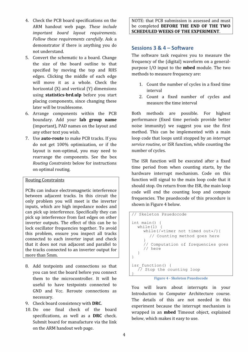
Sessions 3 & 4 – Software The software task requires you to measure the
frequency of the (digital) waveform on a general-
purpose I/O input to the mbed module. The two
methods to measure frequency are:
1. Count the number of cycles in a fixed time
interval
2. Count a fixed number of cycles and
measure the time interval
Both methods are possible. For highest
performance (fixed time periods provide better
noise immunity) we suggest you use the first
method. This can be implemented with a main
loop code that loops until stopped by an interrupt
service routine, or ISR function, while counting the
number of cycles.
The ISR function will be executed after a fixed
time period from when counting starts, by the
hardware interrupt mechanism. Code on this
function will signal to the main loop code that it
should stop. On return from the ISR, the main loop
code will end the counting loop and compute
frequencies. The psuedocode of this procedure is
shown in Figure 4 below.
// Skeleton Psuedocode
int main() { while(1) {
while(/*timer not timed out*/){
// Counting method goes here
} // Computation of frequencies goes
// here
} }
isr_function() { // Stop the counting loop
} Figure 4 - Skeleton Psuedocode
You will learn about interrupts in your
Introduction to Computer Architecture course.
The details of this are not needed in this
experiment because the interrupt mechanism is
wrapped in an mbed Timeout object, explained
below, which makes it easy to use.

5
Using an interrupt in this manner has the
advantage that the main counting loop
computation time will be smaller, which means
the counting loop will work for higher input
frequencies. The mbed platform has high-level
support for such interrupts (e.g. the Timeout
class), which makes this straightforward even if
you have no knowledge of the underlying
mechanism.
Your final deliverable in this experiment will be to
implement embedded code on the mbed that will
measure the frequency of multiple
microcontroller input pins driven by logic level
waveforms. Higher maximum frequencies
measured are desirable.
Counting Loop Basics
Figures 5 and 6 show two different
implementations of the pseudocode needed for
mbed to count the number of cycles of a digital
input. In Figure 5, the outer loop code is executed
once per cycle of the input. The two inner loops
each execute for the time the input is low and
high, respectively. In Figure 6 the loop executes
continuously.
count = 0;
// Set up Timeout object to change a // global variable after T ms.
// This loop executes till Timeout // happens.
while (/*timer has not timed out*/) {
while (pin == 0) {
pin = iopin();
// Read digital value on I/O pin // into pin
}
while (pin == 1) { pin = iopin();
// Read digital value of I/O pin // into pin
}
count = count + 1; }
Figure 5 - Pseudocode to count number of input cycles: version 1
count = 0; // Set up Timeout object to change a
// global variable after T ms. // This loop executes till Timeout // happens.
while (/*timer has not timed out*/) {
pin = iopin(); // Read digital value on I/O pin into
// pin
if (pin != pin_slave) { count = count + 1;
pin_slave = pin; }
} Figure 6 - Pseudocode to count number of input cycles:
version 2
Q Which pseudocode would be possible to adapt
to measure multiple input frequencies during the
same period?
For each pseudocode or for the one you decide to
use:
Q How does the value of count relate to the timer
period and the input frequency?
Q How could the algorithm be adapted to measure
multiple input frequencies simultaneously?
Q What happens to these loops if the input
frequency is too high?
Q* How would an input which has an asymmetric
duty cycle (e.g. 1 for 10 ns, 0 for 20 ns) affect the
maximum frequency at which the code will work?
Q* Is there a minimum frequency which can be
detected?
You may be able to answer these questions
theoretically and in any case will verify your
answers experimentally.
Software Implementation and Testing
Using your mbed module and the instructions on
the handout page, set up for an mbed account on
the mbed website (mbed.org). (You should wait at
least 30 minutes or so after setting up the first
account before repeating the process). You may
use either account for the experiments.
When signed in to the mbed website note the
tabs:

6
Compiler: Gives you a cloud-based
workspace from which you can write,
compile and download your programs.
Handbook: Quick reference on the
standard mbed I/O functions (API).
Cookbook: Extensive reference on other
code including the EAOLED code that
controls the display on your board.
The mbed module has a USB interface entirely
separate from the microcontroller, which
enumerates as a USB flash disk. This disk can
contain multiple files and is seen under windows.
When the microcontroller starts, it automatically
downloads the most recent hex file as a program
and runs it. This is what you usually want.
When you use a module it may already have files
on it. You can ignore these. It is possible to delete
files from the module, but you must wait enough
time for the operation to complete (it is slow). If
you don’t do this, you corrupt the USB flash disk.
In this case, should it happen, the solution is to
reformat the disk and start again. Since everything
on the USB disk is temporary this is not a
problem. Nevertheless, to save time, you are
advised to make no changes to files on the flash
disk unless this becomes necessary - for example
if the disk is full.
List of actions for this task:
1. Download the EAOLED zip file from the
ARM handout web page.
2. Log into your mbed account and open up
the cloud compiler.
3. You will need to import the EAOLED zip
file as a program into your mbed
compiler (right-click on "My Programs"
from the Program Workspace panel and
select "Import Program" option. Select the
"Upload" tab and browse to downloaded
EAOLED zip file. When it shows up on the
list, click "Import!").
4. The imported file (main-test-OLED) is a
sample main file that demonstrates how to
write to the OLED and use Timeout
objects. Before compiling the code to run
on your mbed module, it is likely that the
library dependencies are out of date and
needs to be updated. Expand your
program directory from the Program
Workspace panel and click on mbed
build (cog symbol). Click "Update" on the
Program Details panel on the right.
5. You can now modify the sample file, or
write your own main file, to implement
your code. Using the mbed compiler and
API, write code that could implement a
single touch switch by detecting the input
frequency on a pin.
The following mbed C++ API classes will be
needed: Timeout, DigitalIn (see documentation
in mbed web handbook). You are however free to
use others as necessary. To debug and instrument
your software initially, write code that will display
the measured frequency from an input pin on the
OLED display. Make sure that the measurement
time can easily be changed.
Because the Timeout object code operates
asynchronously of the main loop code, it is
essential that all global variables used to
communicate between Timeout code and main
loop code are declared volatile. You will find
an example of this in the skeleton code.
Q The Timeout object in the mbed API is
implemented by an interrupt. When the specified
function terminates, the interrupt will return and
execution resume as though the Timeout had
never happened. How does the Timeout code
signal to the main code that the Timeout has
happened?
Q* Why is it not a good idea to put code executed
after the timeout into the Timeout function, rather
than the main code. (This is possible, but not
recommended).
Q** Why is the volatile declaration needed here
for some global variables?
Test the operation of the software loop before
testing the hardware by modifying each inner
loop so it terminates immediately (version 1) or
so that count is always incremented (version 2).
Observe that the count is correctly displayed on
the OLED and changes as expected if the Timeout
period is changed or the loop time is made shorter
or longer, by adding extra code.

7
Q How do the final value of count, loop time, and
Timeout time relate to each other?
Figure 7 documents which mbed inputs are
available on the IDC breakout adaptor.
GND GND
NC NC
(P0.11) p27 NC NC
1 3 5 7 9
11 13
2 4 6 8
10 12 14
+3.3V out +3.3V out p30 (P0.4) p29 (P0.5) p28 (P0.10) p11 (P0.18) NC
NC pN P0.M
= = =
must be not connected mbed pin N LPC1768 - Port 0, Bit M
TOP VIEW as plugged into breadboard
Pins are as on the DIL adaptor photo above Figure 7 – IDC breakout adaptor pinouts
Use a signal generator for hardware testing. Read
and follow the protocol in Figure 8 before you
touch the hardware. The mbed modules are
fragile and will break if you connect a signal
generator with the wrong output.
IMPORTANT
1. Check scope GND and function generator
GND are connected to board GND on the IDC breakout adaptor.
2. Set scope to measure 3.3VDC. Check this is correct by measuring board supply from the IDC breakout adaptor with a scope. This should be 3.3V.
3. Check that function generator square wave output varies between 0 and 3v. Note that this voltage range will require use of the offset knob.
4. ARE YOU SURE ALL IS OK? ERROR WILL BREAK mbed. Connect the signal generator.
5. Make sure you do not normally connect anything to the +3.3v supply from the adaptor. It is permitted if necessary to
construct a Schmidt trigger oscillator on the breadboard using the +3.3v supply, be very careful to check connections. Figure 8 - Important Safety Instructions
Connect the waveform to one of the mbed inputs
using the supplied connection lead.
Debug your code and determine what the
maximum frequency it can measure is.
Q How does the maximum frequency vary with
asymmetric input waveforms?
Q* Can you predict this from your earlier
measurements?
In order to use this software with your n touch
switches (n = 4 typically) you will need to
measure n input frequencies on different input
pins. If you do this one after another, which is
simplest, your switch delay time will be larger
than if you do it in parallel. Of course using a
shorter measurement time interval would solve
the problem but you will find that times shorter
than 20ms have much larger interference from
mains and are therefore less good.
Q* Why might time intervals shorter than 20ms
have larger mains interference?
Q** Can you find an analytic expression for the
likely error due to mains interference as a
function of measurement time assuming that
mains waveform is a 50Hz sinusoid? What other
assumptions do you make in developing this?
To finish the experiment implement and test
software which measures simultaneously multiple
switch input frequencies.
Further Optimization (Optional)
This section is optional in case you finish early; it
contains some ideas for speeding up the counting
code, some of which are simple while others quite
complex. Don’t attempt them unless you have
completed the rest of the activity. You are also
encouraged to use your own initiative to
investigate or improve the code, so you are not
limited to the ideas here.
1. The PortIn API class is more difficult to
use than DigitalIn, but considerably faster.

8
2. The input lines from the hardware are
routed to different bits on the same
LPC1768 port. They can therefore be input
in parallel, as a single 32 bit word. It is
possible to implement counting as a
sequence of 32 bit logical operations, with
a number of registers holding the bottom
few bits of the required count. Note that C
“bitwise logical” operations (& | ^ ~) will
compile to ARM logical operations.
3. Migrating parts of the code to assembler
will possibly (but not necessarily) speed
up the code. See documentation under
mbed site for how to write assembler and
note that the Keil tools can also be used.
Not however for the fainthearted. The
mbed module uses an advanced ARM ISA,
which is backwards compatible with the
ARM7 instructions taught in Introduction
to Computer Architecture. Read the Keil
ARM documentation for details.
4. Note that the code you test in this
experiment will be used in the SWITCH
experiment Spring Term. You will make
further enhancements and changes to it at
that point.
Further Information If you are interested in this experiment the
following resources will take you further and may
be useful in future project work:
Capacitive touch-switches are now widely
used, as are touch-screens. One popular
implementation, with sophisticated
special-purpose ICs, determines the
position of a finger by the ratio of
capacitance changes in an XY grid of wires.
This allows position sensing on a finer grid
than the wires used to sense.
The mbed framework is very easy to use
but inflexible. You can create hex files
compatible with the mbed platform using
Keil tools (see Introduction to Computer
Architecture web page). The mbed
website gives further information. One
advantage that the mbed compiler has
over Keil is that it is not size limited; the
free version of Keil is limited to 32K.
mbed modules cost £40. There is however
a new cheaper module. Also, the NXP
LPC1768 microcontroller is cheap and can
be used on its own with suitable
programming tools, but note the difficulty
in soldering SMT packages.