arm dsp working together
DESCRIPTION
ARM DSP working together. Multicore Training. Agenda. Managing the peripherals and IP in hydrogenous device Linux Device Tree Memory Management Resource Management ARM-DSP communication Architecture. Challenges. How to use peripherals and other Ip in ARM and DSP KeyStone devices? - PowerPoint PPT PresentationTRANSCRIPT
Multicore Training
ARM DSP working together
Multicore Training
Multicore Training
Agenda
• Managing the peripherals and IP in hydrogenous device
• Linux Device Tree• Memory Management• Resource Management• ARM-DSP communication Architecture
Multicore Training
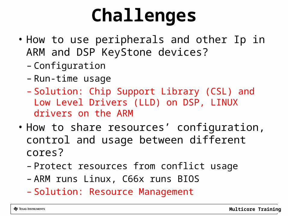
Challenges• How to use peripherals and other Ip in ARM and
DSP KeyStone devices?– Configuration– Run-time usage– Solution: Chip Support Library (CSL) and Low Level
Drivers (LLD) on DSP, LINUX drivers on the ARM• How to share resources’ configuration, control
and usage between different cores?– Protect resources from conflict usage– ARM runs Linux, C66x runs BIOS– Solution: Resource Management
Multicore Training
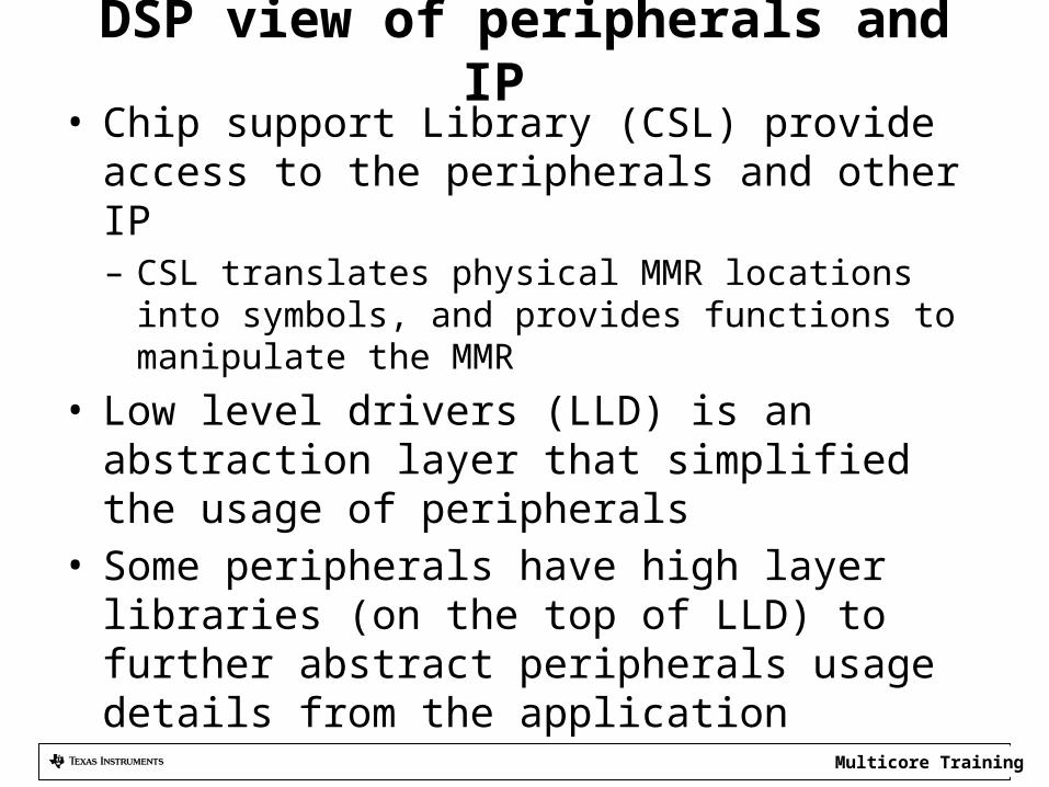
DSP view of peripherals and IP • Chip support Library (CSL) provide access to the
peripherals and other IP– CSL translates physical MMR locations into symbols, and
provides functions to manipulate the MMR• Low level drivers (LLD) is an abstraction layer that
simplified the usage of peripherals• Some peripherals have high layer libraries (on the top
of LLD) to further abstract peripherals usage details from the application
Multicore Training
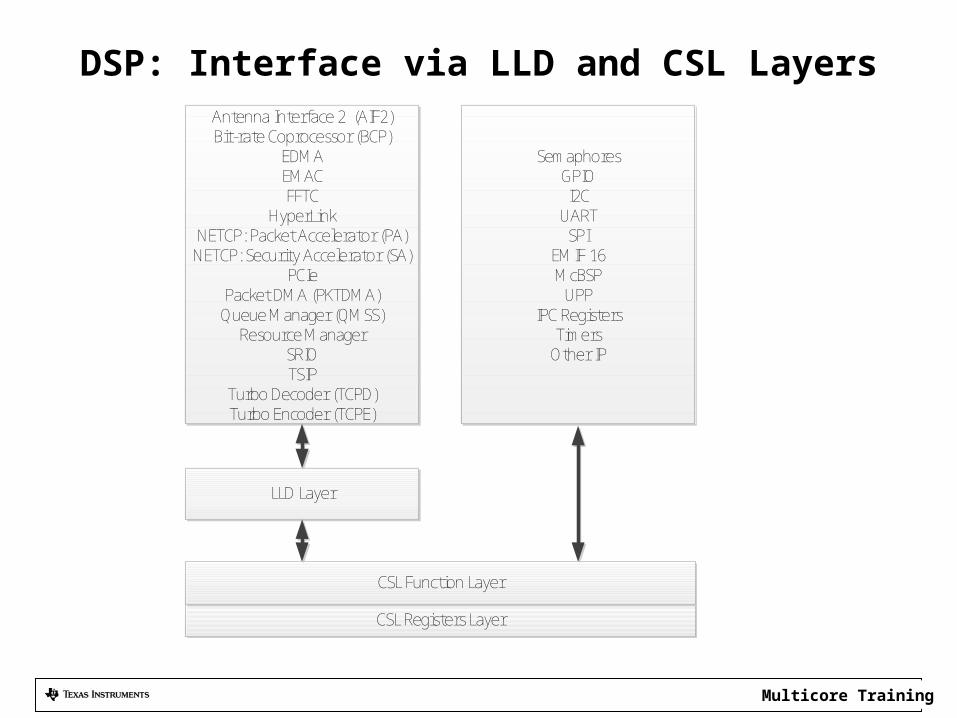
DSP: Interface via LLD and CSL Layers
CSL Registers Layer
CSL Function Layer
LLD Layer
Antenna Interface 2 (AIF2)Bit-rate Coprocessor (BCP)
EDMAEMACFFTC
HyperLinkNETCP: Packet Accelerator (PA)
NETCP: Security Accelerator (SA)PCIe
Packet DMA (PKTDMA)Queue Manager (QMSS)
Resource ManagerSRIOTSIP
Turbo Decoder (TCPD)Turbo Encoder (TCPE)
SemaphoresGPIOI2C
UARTSPI
EMIF 16McBSP
UPPIPC Registers
TimersOther IP
Multicore Training
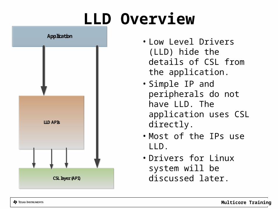
LLD Overview• Low Level Drivers (LLD)
hide the details of CSL from the application.
• Simple IP and peripherals do not have LLD. The application uses CSL directly.
• Most of the IPs use LLD.• Drivers for Linux system
will be discussed later.CSL layer (API)
LLD APIs
Application
Multicore Training
Linux Control peripherals and IP • MMU controls memory access for user mode
in Linux. Application does not see physical address
• Device drivers can be called by the applications, they can access physical memory
• Linux Device Drivers provide– Modularity– Standard interface– Standard structure
Multicore Training
What are Linux Device Drivers?
• Link between standard interface and the hardware• Hides the complexity of device operation from the
user• Provides standard API to use the device• Maps the API to one or more functions that
manipulate the specific hardware device.• Linux kernel modularity scheme enables easy
plugging of new device drivers to a kernel.
Multicore Training
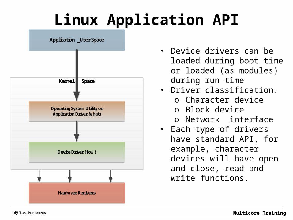
Linux Application API
• Device drivers can be loaded during boot time or loaded (as modules) during run time
• Driver classification:o Character deviceo Block deviceo Network interface
• Each type of drivers have standard API, for example, character devices will have open and close, read and write functions.
Hardware Registers
Application _User Space
Kernel Space
Device Driver (How)
Operating System Utility orApplication Driver (what)
Multicore Training
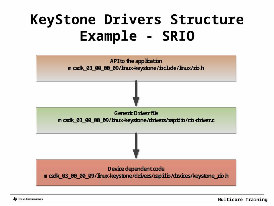
KeyStone Drivers StructureExample - SRIO
Device dependent codemcsdk_03_00_00_09/linux-keystone/drivers/rapidio/drvices/keystone_rio.h
Generic Driver filemcsdk_03_00_00_09/linux-keystone/drivers/rapidio/rio-driver.c
API to the applicationmcsdk_03_00_00_09/linux-keystone/include/linux/rio.h
Multicore Training11
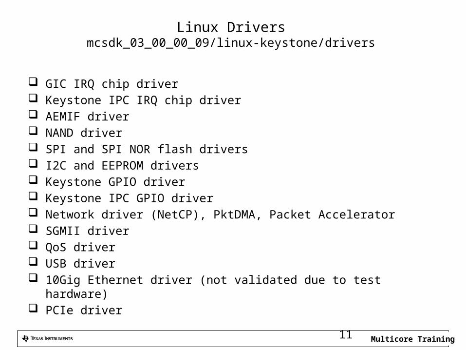
Linux Driversmcsdk_03_00_00_09/linux-keystone/drivers
GIC IRQ chip driver Keystone IPC IRQ chip driver AEMIF driver NAND driver SPI and SPI NOR flash drivers I2C and EEPROM drivers Keystone GPIO driver Keystone IPC GPIO driver Network driver (NetCP), PktDMA, Packet Accelerator SGMII driver QoS driver USB driver 10Gig Ethernet driver (not validated due to test hardware) PCIe driver
Multicore Training
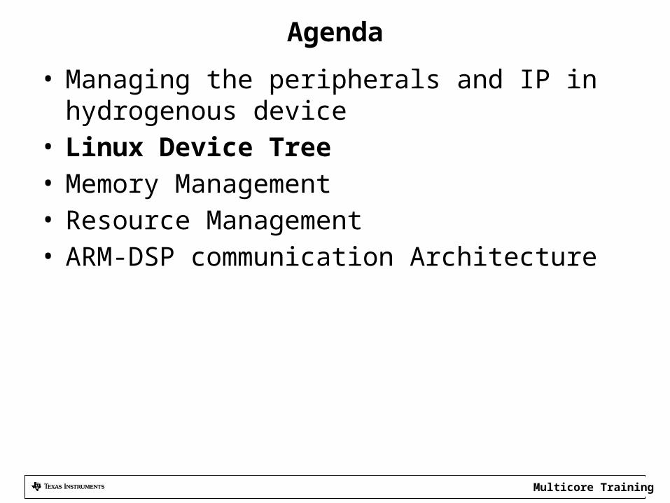
Agenda
• Managing the peripherals and IP in hydrogenous device
• Linux Device Tree• Memory Management• Resource Management• ARM-DSP communication Architecture
Multicore Training
Linux Device Tree
• How do Linux drivers know what resources are available and what are the physical attributes of the resources?
The device tree • Linux Device tree is an ASCII file *.dts that
describes the resources available to Linux. A compiled version of the file *.dtb is used by the linux system
• Device tree source code has a well defined syntax.
Multicore Training
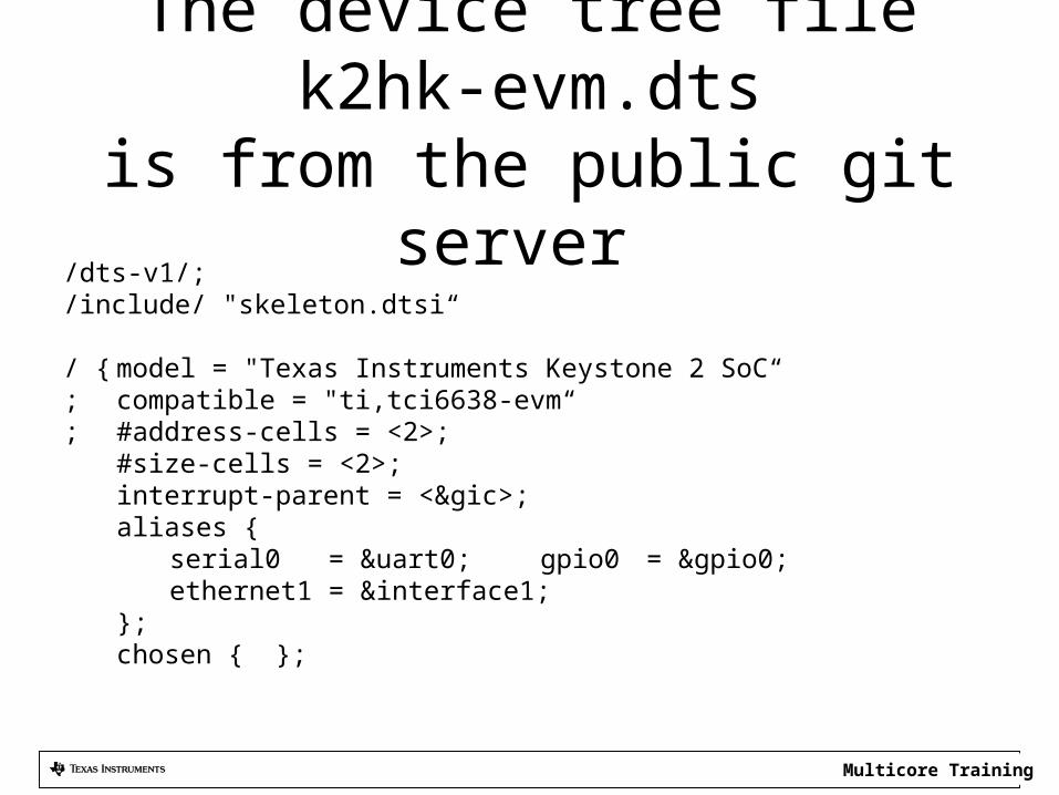
The device tree file k2hk-evm.dtsis from the public git server
/dts-v1/;/include/ "skeleton.dtsi“
/ { model = "Texas Instruments Keystone 2 SoC“; compatible = "ti,tci6638-evm“; #address-cells = <2>;
#size-cells = <2>;interrupt-parent = <&gic>;aliases {
serial0 = &uart0; gpio0 = &gpio0;ethernet1 = &interface1;
};chosen { };
Multicore Training
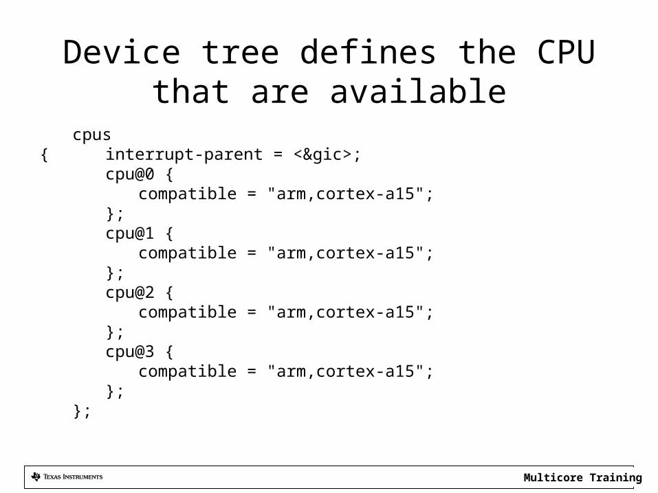
Device tree defines the CPU that are available
cpus { interrupt-parent = <&gic>;
cpu@0 {compatible = "arm,cortex-a15";
};cpu@1 {
compatible = "arm,cortex-a15";};cpu@2 {
compatible = "arm,cortex-a15";};cpu@3 {
compatible = "arm,cortex-a15";};
};
Multicore Training
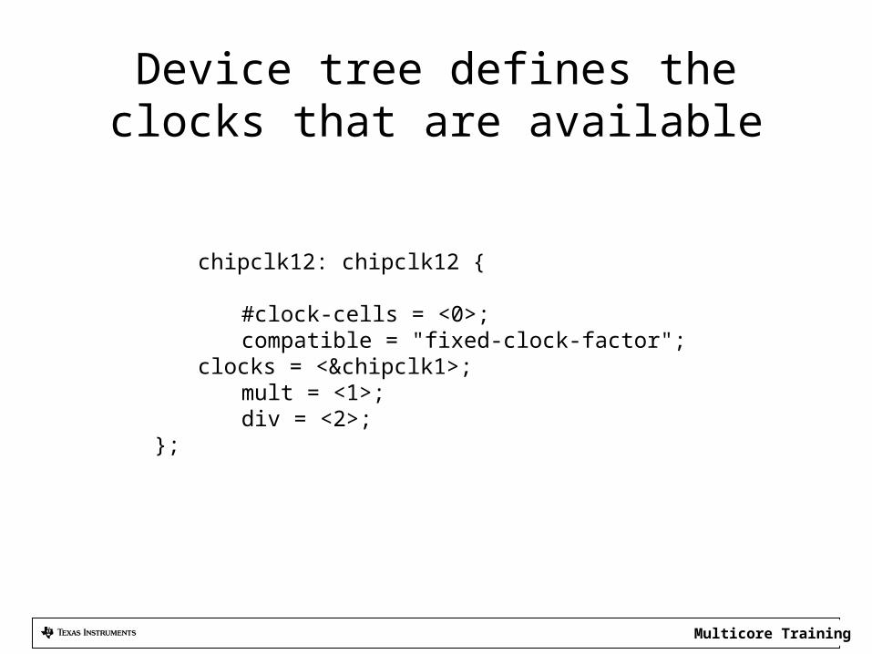
Device tree defines the clocks that are available
chipclk12: chipclk12 {
#clock-cells = <0>;compatible = "fixed-clock-factor";
clocks = <&chipclk1>;mult = <1>;div = <2>;
};
Multicore Training
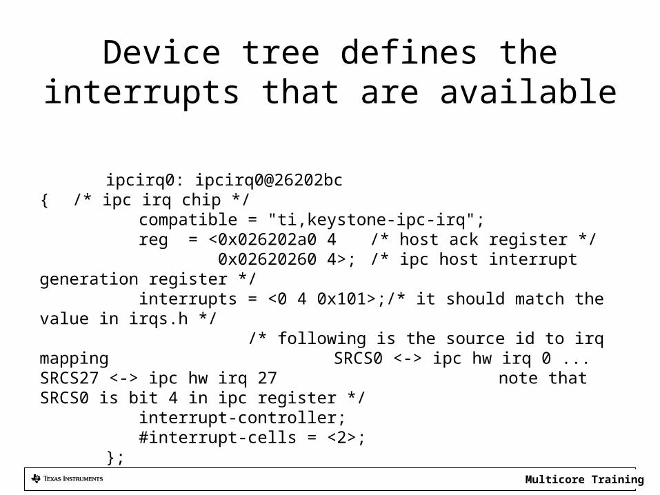
Device tree defines the interrupts that are available
ipcirq0: ipcirq0@26202bc { /* ipc irq chip */
compatible = "ti,keystone-ipc-irq";reg = <0x026202a0 4 /* host ack register */ 0x02620260 4>; /* ipc host interrupt
generation register */interrupts = <0 4 0x101>;/* it should match the value in
irqs.h */ /* following is the source
id to irq mapping SRCS0 <-> ipc hw irq 0 ... SRCS27 <-> ipc hw irq 27
note that SRCS0 is bit 4 in ipc register */interrupt-controller;#interrupt-cells = <2>;
};
Multicore Training
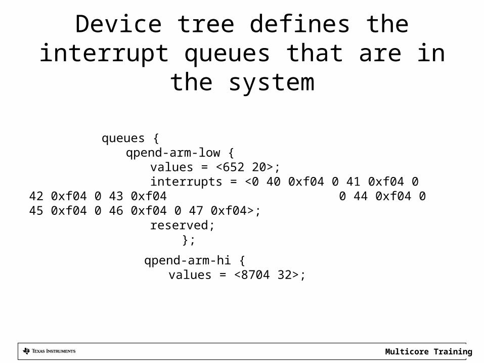
Device tree defines the interrupt queues that are in the system
queues {qpend-arm-low {
values = <652 20>;interrupts = <0 40 0xf04 0 41
0xf04 0 42 0xf04 0 43 0xf04 0 44 0xf04 0 45 0xf04 0 46 0xf04 0 47 0xf04>;
reserved; };
qpend-arm-hi { values = <8704 32>;
Multicore Training
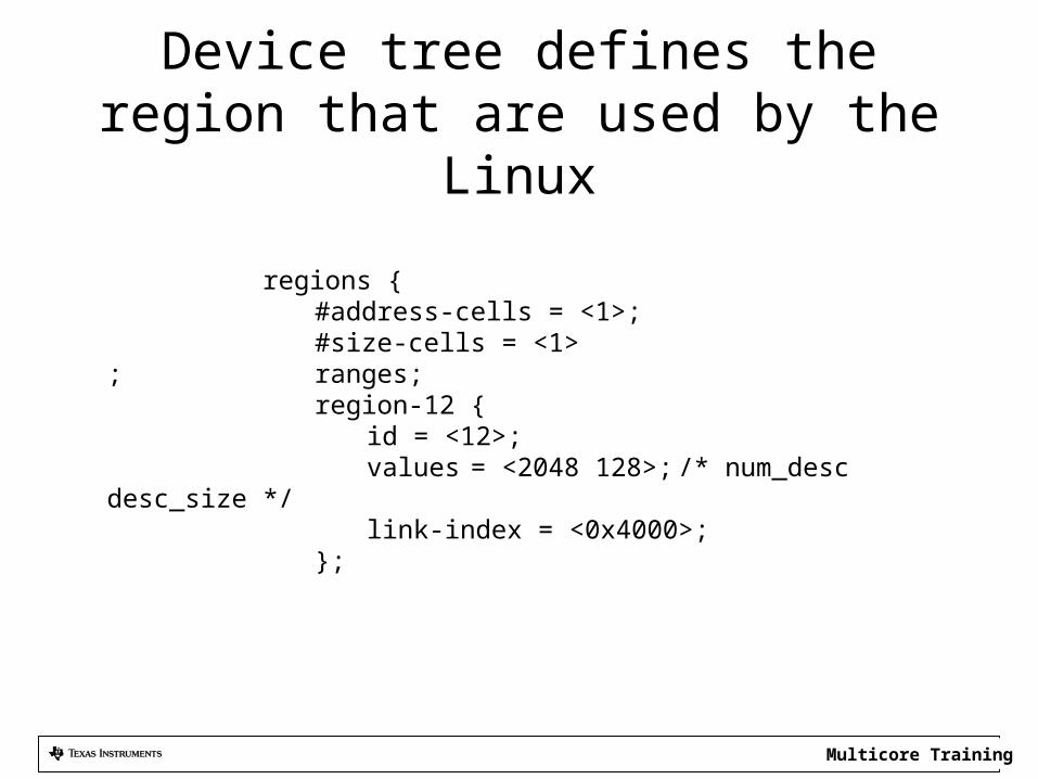
Device tree defines the region that are used by the Linux
regions {#address-cells = <1>;#size-cells = <1>
; ranges;region-12 {
id = <12>;values = <2048 128>;
/* num_desc desc_size */link-index = <0x4000>;
};
Multicore Training
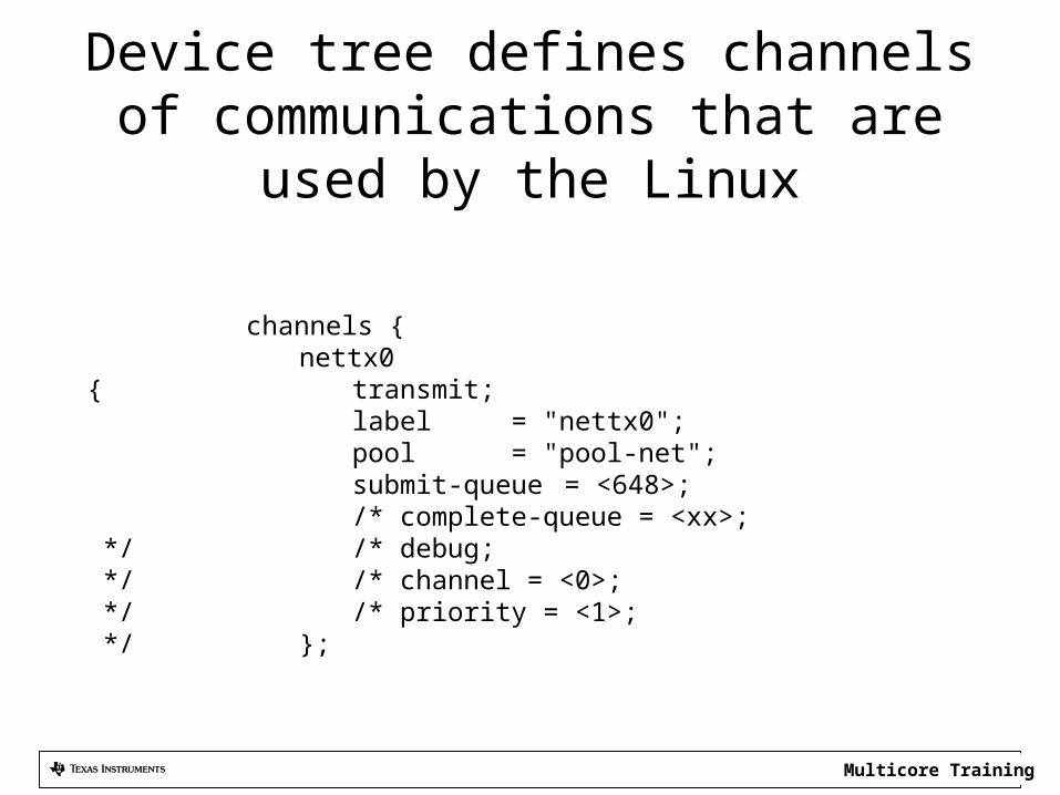
Device tree defines channels of communications that are used by the Linux
channels {nettx0
{ transmit;label = "nettx0";pool = "pool-net";submit-queue = <648>;/* complete-queue = <xx>;
*/ /* debug; */ /* channel = <0>; */ /* priority = <1>; */ };
Multicore Training
A word about ARM – DSP resource Management
• When ARM and DSP co-exist, some resources are managed by the resource manager server
• Memories are managed differently. The next few slides describe how memories are managed in DSP-Linux system
Multicore Training
Agenda
• Managing the peripherals and IP in hydrogenous device
• Linux Device Tree• Memory Management• Resource Management• ARM-DSP communication Architecture
Multicore Training23
Memory defined in the Device Tree• In the device tree we define what memories will be
used by the Linux and what by the DSP*• During boot time (U-BOOT) builds a device tree table
and updates it based on U-BOOT environment• Device Tree for the EVM is tci6638-evm.dts. It defines
several memories. It defines the total logical memory and what part of it will be used by the kernel, and it defines what memories will be reserved for the DSP
Multicore Training24
Disclaimer
• The Following slides show how TI implementation that runs on TCIEVM6638K2K words
• Other implementations may be different
Multicore Training25
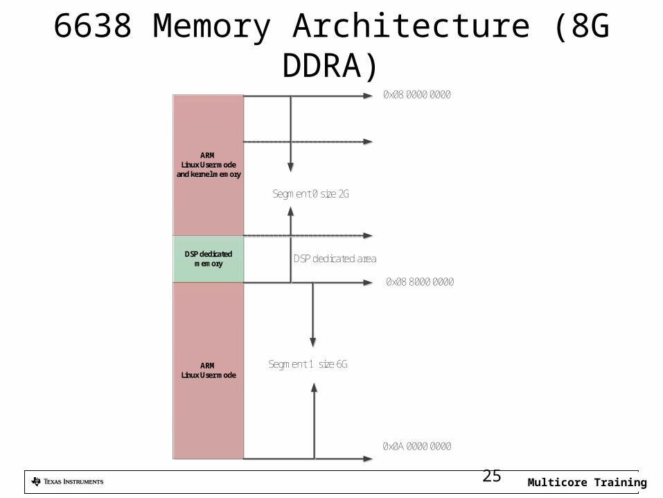
6638 Memory Architecture (8G DDRA)
DSP dedicated memory
ARMLinux User mode
and kernel memory
Segment 0 size 2G
0x08 0000 0000
0x0A 0000 0000
ARMLinux User mode
Segment 1 size 6G
DSP dedicated area
0x08 8000 0000
Multicore Training26
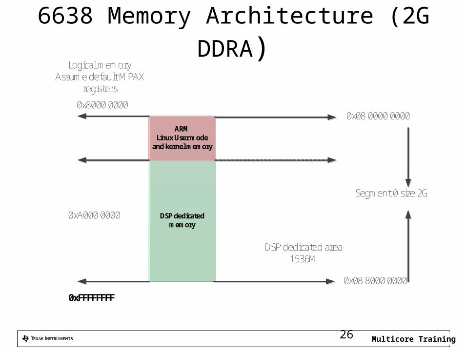
6638 Memory Architecture (2G DDRA)
DSP dedicated memory
ARMLinux User mode
and kernel memory
Segment 0 size 2G
0x08 0000 0000
DSP dedicated area 1536M
0x08 8000 0000
Logical memoryAssume default MPAX
registers
0x8000 0000
0xA000 0000
0xFFFFFFFF
Multicore Training27
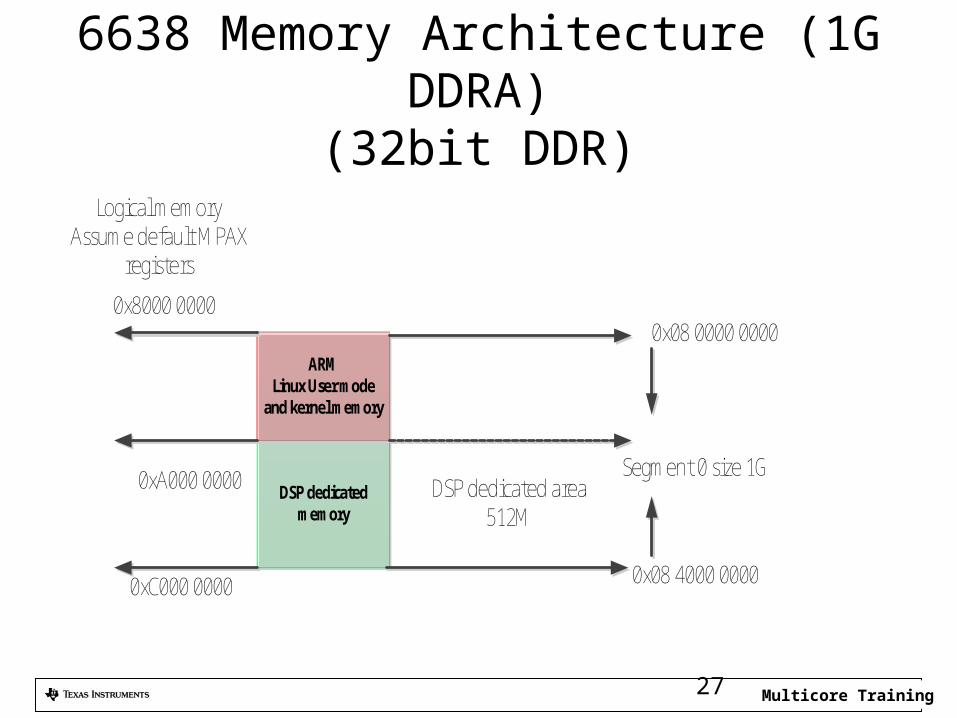
6638 Memory Architecture (1G DDRA)(32bit DDR)
DSP dedicated memory
ARMLinux User mode
and kernel memory
Segment 0 size 1G
0x08 0000 0000
DSP dedicated area 512M
0x08 4000 0000
Logical memoryAssume default MPAX
registers
0x8000 0000
0xA000 0000
0xC000 0000
Multicore Training28
DDR and MSM Memories• DSP and other masters translate the 32 bit logical
address into 36 (40) bits physical address using MPAX registers
• ARM MMU translates 32 bit logical memory into 40 bits physical memory
• In TI implementation, U-BOOT defines the memory that is available to the MMU
• Starting from device tree and modifies it • Arm A15 in KeyStone uses large Physical Address
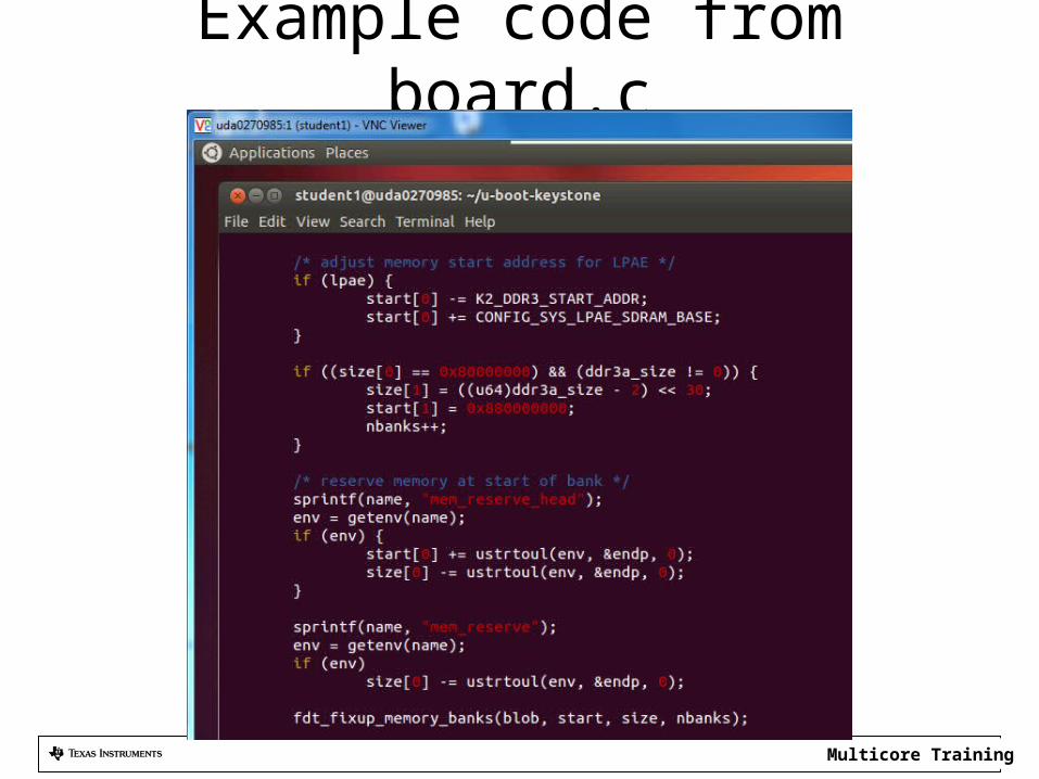
Extension mode • The file board.c (see later) defines the physical
memories for the MMU
Multicore Training29
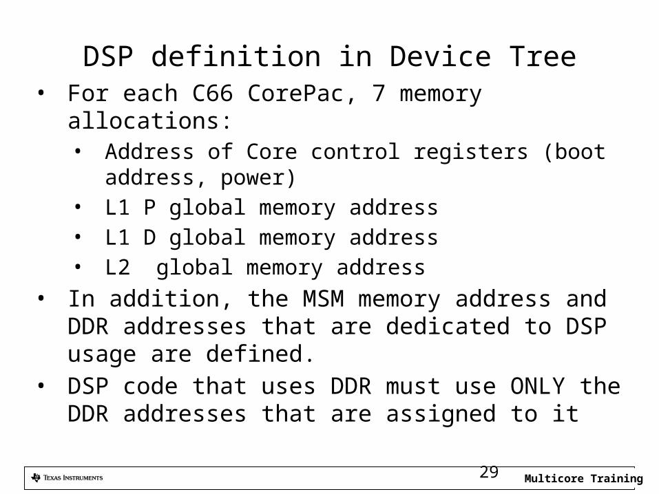
DSP definition in Device Tree• For each C66 CorePac, 7 memory allocations:
• Address of Core control registers (boot address, power)
• L1 P global memory address• L1 D global memory address• L2 global memory address
• In addition, the MSM memory address and DDR addresses that are dedicated to DSP usage are defined.
• DSP code that uses DDR must use ONLY the DDR addresses that are assigned to it
Multicore Training30
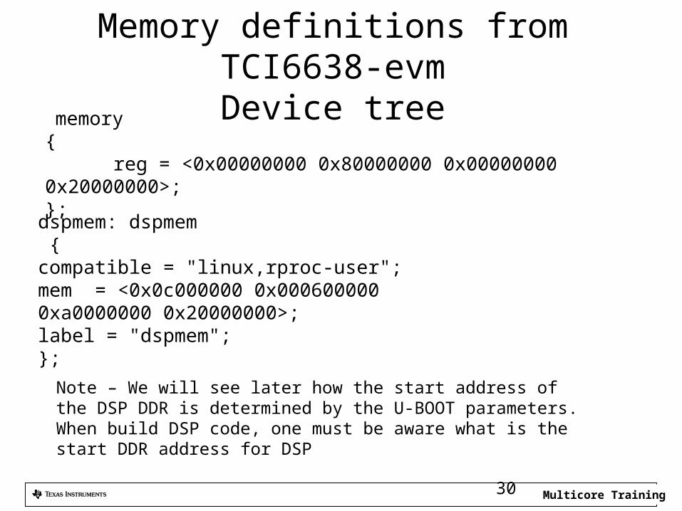
Memory definitions from TCI6638-evmDevice tree
dspmem: dspmem {compatible = "linux,rproc-user";mem = <0x0c000000 0x000600000
0xa0000000 0x20000000>;label = "dspmem";};
memory { reg = <0x00000000 0x80000000 0x00000000 0x20000000>; };
Note – We will see later how the start address of the DSP DDR is determined by the U-BOOT parameters. When build DSP code, one must be aware what is the start DDR address for DSP
Multicore Training31
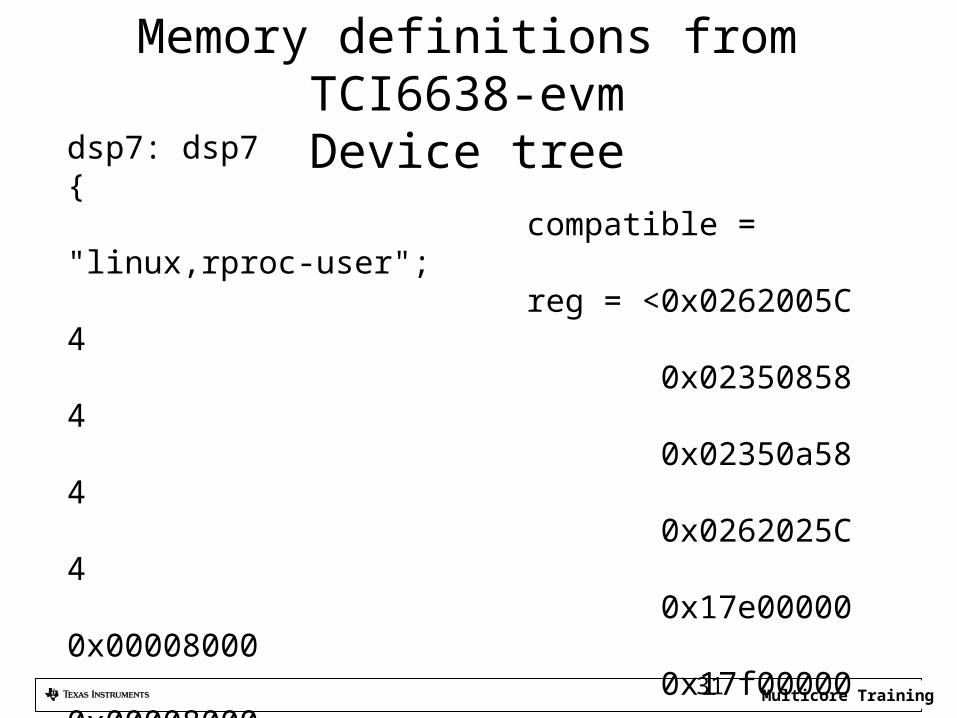
Memory definitions from TCI6638-evmDevice treedsp7: dsp7
{ compatible = "linux,rproc-user"; reg = <0x0262005C 4 0x02350858 4 0x02350a58 4 0x0262025C 4 0x17e00000 0x00008000 0x17f00000 0x00008000 0x17800000 0x00100000>; reg-names = "boot-address", "psc-mdstat", "psc-mdctl", "ipcgr", "l1pram", "l1dram", "l2ram";
Multicore Training
U-BOOT and mem_reserve• Two segment of memory are defined for the MMU to
use. • The first starts at physical address 0x08 0000 0000 and
size of 2G • The second segment starts at 0x08 8000 0000 and size
6G • Part of the first segment of memory is reserved for the
DSP memory. This is used to load programs and data from the ARM user’s domain to the DSP memory
• The size of the DSP reserve memory is defined in U-BOOT. It is called mem_resereve. A default size is 512M – 0x2000 0000 32
Multicore Training
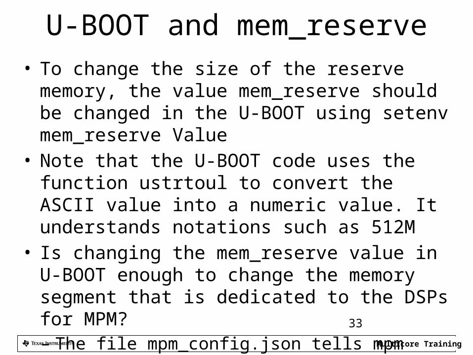
U-BOOT and mem_reserve• To change the size of the reserve memory, the value
mem_reserve should be changed in the U-BOOT using setenv mem_reserve Value
• Note that the U-BOOT code uses the function ustrtoul to convert the ASCII value into a numeric value. It understands notations such as 512M
• Is changing the mem_reserve value in U-BOOT enough to change the memory segment that is dedicated to the DSPs for MPM?– The file mpm_config.json tells mpm what memories are
available. It must agree with the device tree and the U-BOOT 33
Multicore Training
Example code from board.c
34
Multicore Training35
MPM Configuration
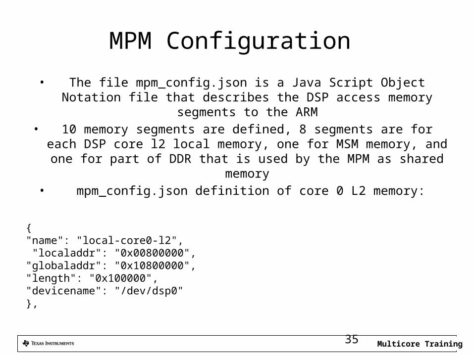
• The file mpm_config.json is a Java Script Object Notation file that describes the DSP access memory segments to the ARM
• 10 memory segments are defined, 8 segments are for each DSP core l2 local memory, one for MSM memory, and one for
part of DDR that is used by the MPM as shared memory• mpm_config.json definition of core 0 L2 memory:
{"name": "local-core0-l2", "localaddr": "0x00800000","globaladdr": "0x10800000","length": "0x100000","devicename": "/dev/dsp0"},
Multicore Training36
MPM Configuration (2)
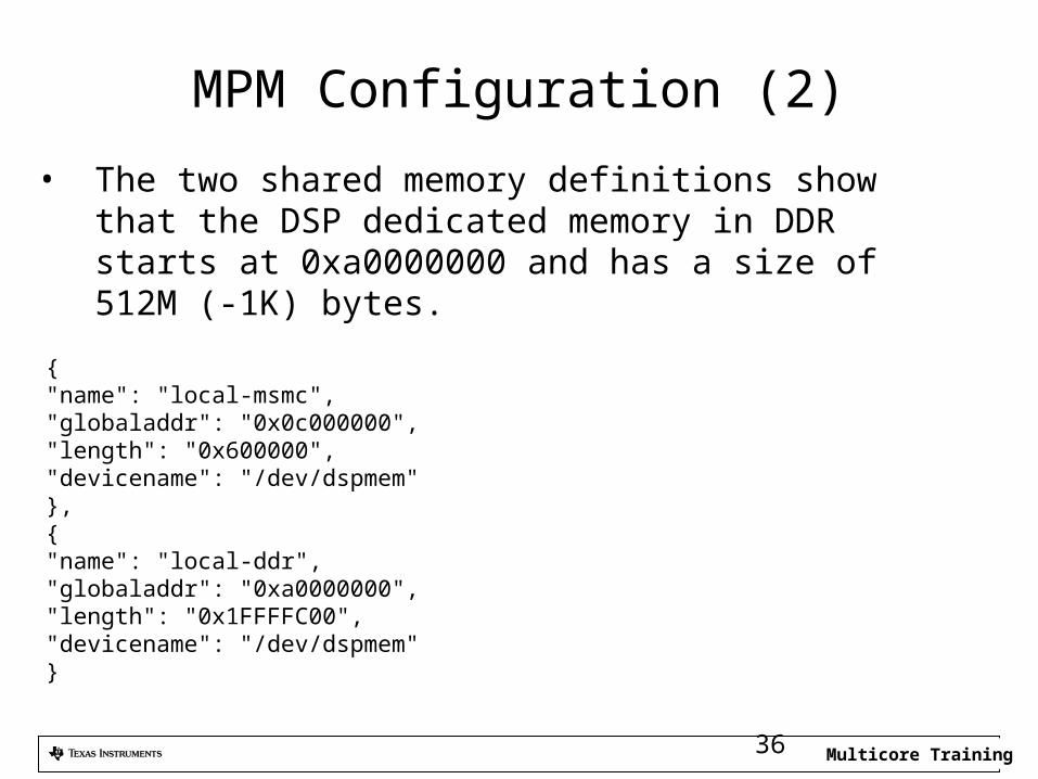
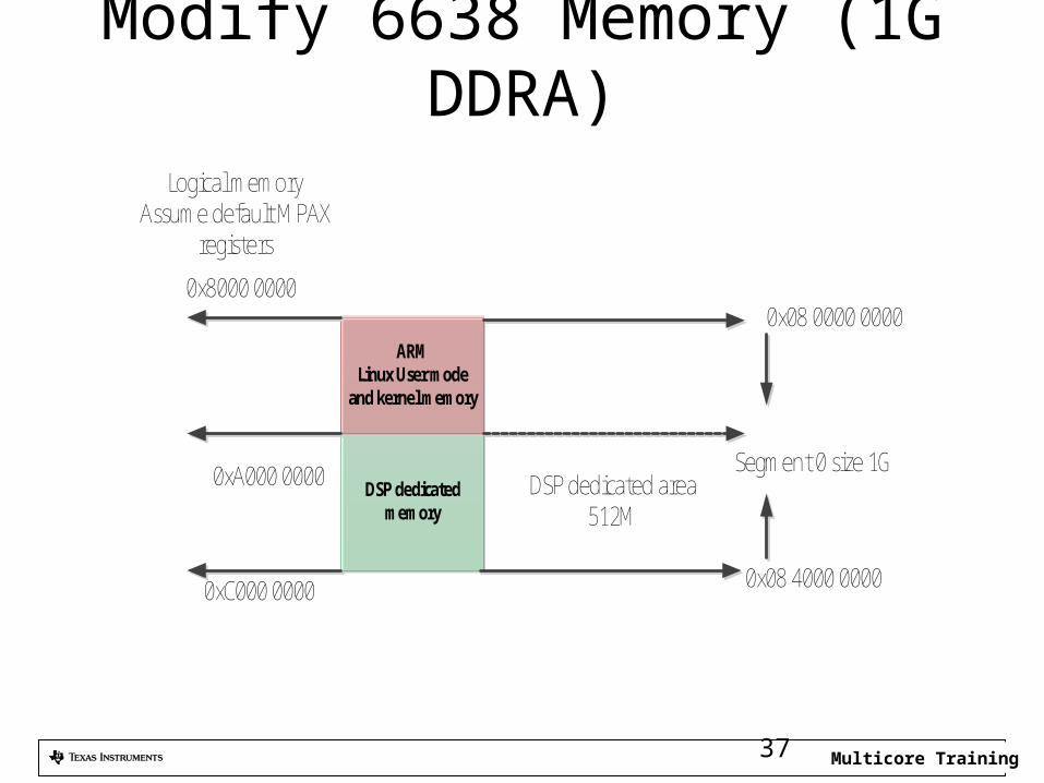
• The two shared memory definitions show that the DSP dedicated memory in DDR starts at 0xa0000000 and has a size of 512M (-1K) bytes.
{"name": "local-msmc","globaladdr": "0x0c000000","length": "0x600000","devicename": "/dev/dspmem"},{"name": "local-ddr","globaladdr": "0xa0000000","length": "0x1FFFFC00","devicename": "/dev/dspmem"}
Multicore Training37
Modify 6638 Memory (1G DDRA)
DSP dedicated memory
ARMLinux User mode
and kernel memory
Segment 0 size 1G
0x08 0000 0000
DSP dedicated area 512M
0x08 4000 0000
Logical memoryAssume default MPAX
registers
0x8000 0000
0xA000 0000
0xC000 0000
Multicore Training38
Building DSP code to work with MPM
• DSP projects that use RTSC must define a platform• The standard TI platform (standard = in the
release) was not built to work with MPM• A new platform must be defined• Projects that do not use RTSC must have a linker
command to define the memory structure. The link command must be modified to work with MPM
Multicore Training
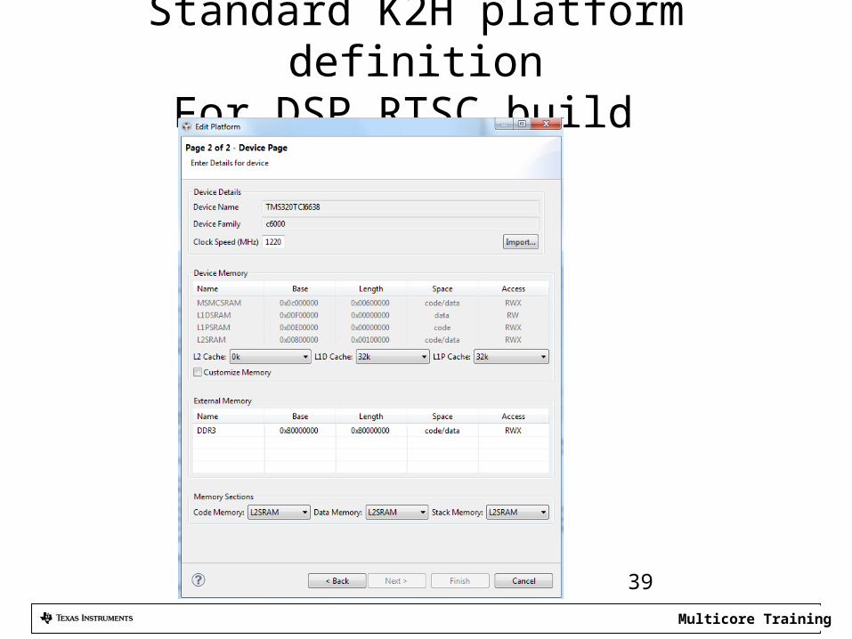
Standard K2H platform definitionFor DSP RTSC build
39
Multicore Training
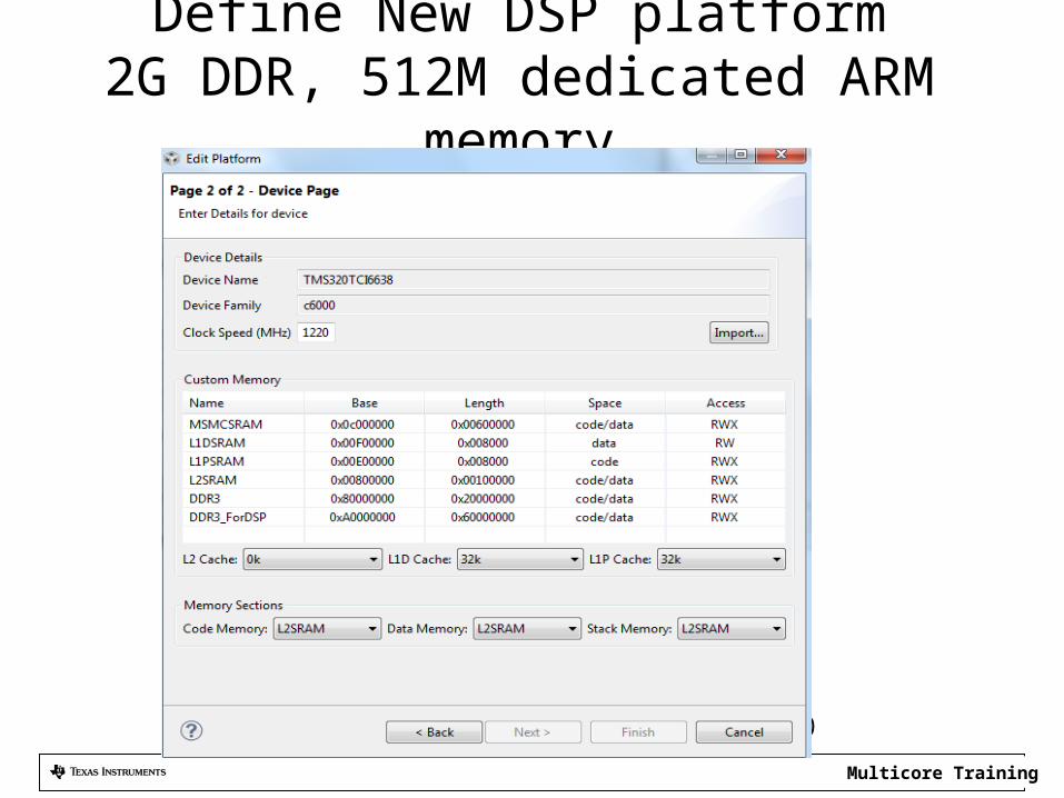
Define New DSP platform2G DDR, 512M dedicated ARM memory
40
Multicore Training
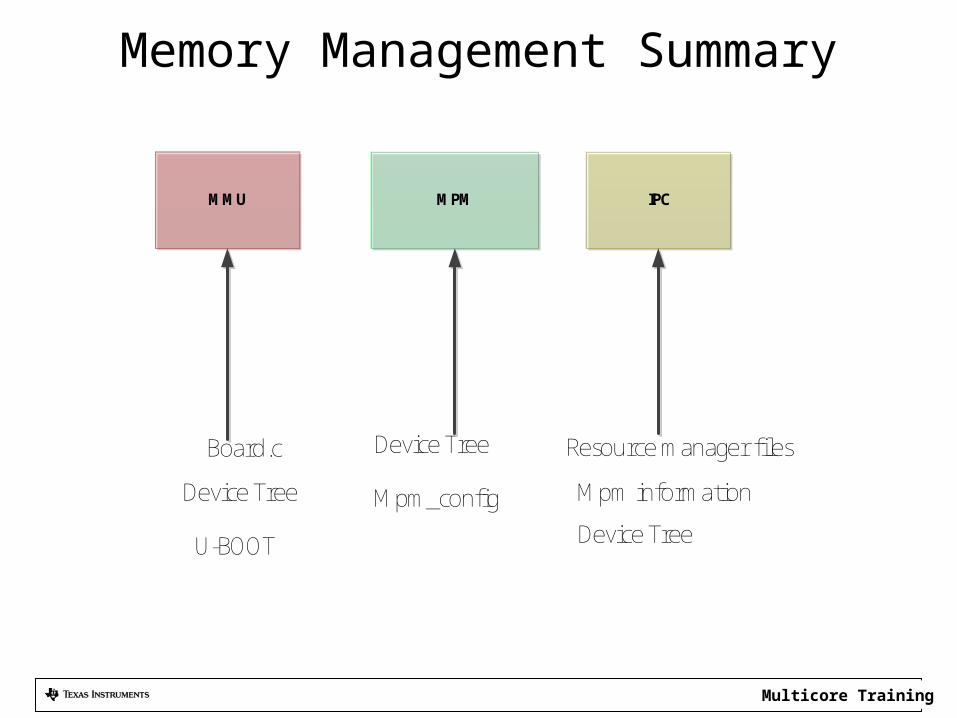
Memory Management Summary
MPMMMU IPC
Board.c Device Tree
Mpm_configDevice Tree
U-BOOT Device Tree
Resource manager files
Mpm information
Multicore Training
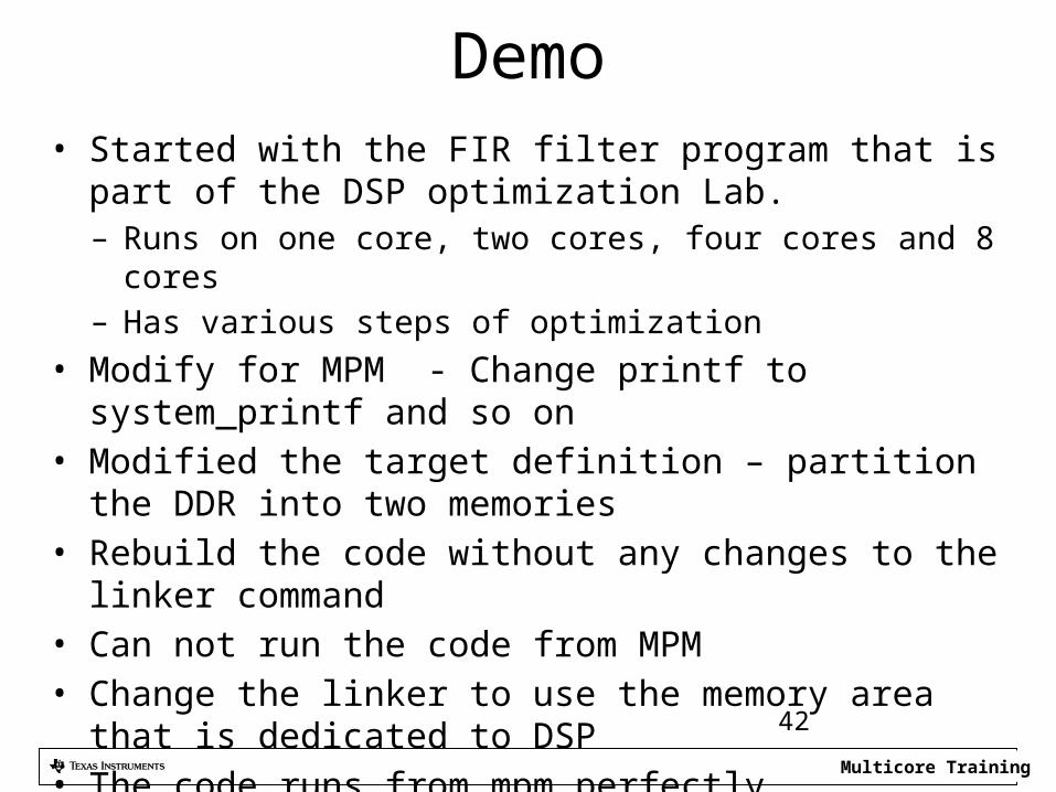
Demo• Started with the FIR filter program that is part of the DSP
optimization Lab. – Runs on one core, two cores, four cores and 8 cores– Has various steps of optimization
• Modify for MPM - Change printf to system_printf and so on• Modified the target definition – partition the DDR into two
memories• Rebuild the code without any changes to the linker command• Can not run the code from MPM• Change the linker to use the memory area that is dedicated to
DSP• The code runs from mpm perfectly
42
Multicore Training
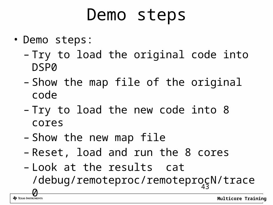
Demo steps• Demo steps:
– Try to load the original code into DSP0– Show the map file of the original code– Try to load the new code into 8 cores– Show the new map file– Reset, load and run the 8 cores– Look at the results cat
/debug/remoteproc/remoteprocN/trace0
43
Multicore Training
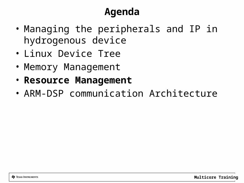
Agenda
• Managing the peripherals and IP in hydrogenous device
• Linux Device Tree• Memory Management• Resource Management• ARM-DSP communication Architecture
Multicore Training
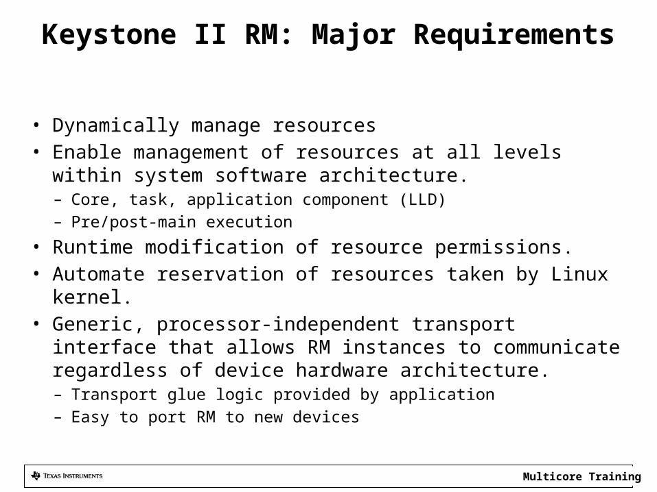
Keystone II RM: Major Requirements
• Dynamically manage resources • Enable management of resources at all levels within system
software architecture.– Core, task, application component (LLD)– Pre/post-main execution
• Runtime modification of resource permissions.• Automate reservation of resources taken by Linux kernel.• Generic, processor-independent transport interface that allows
RM instances to communicate regardless of device hardware architecture.– Transport glue logic provided by application– Easy to port RM to new devices
Multicore Training
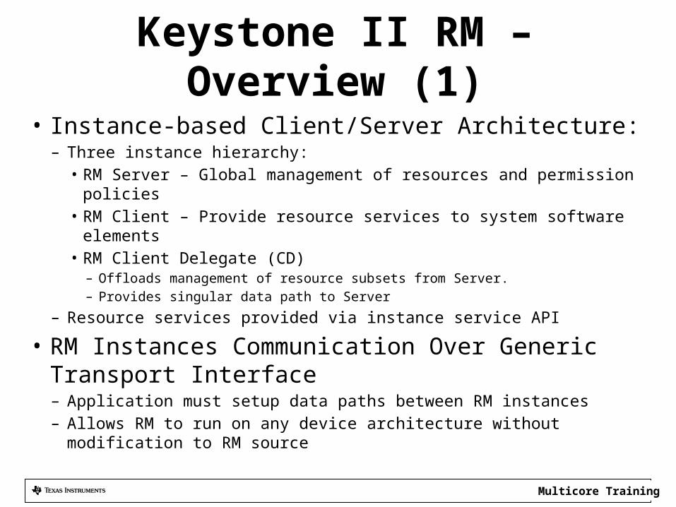
Keystone II RM – Overview (1)• Instance-based Client/Server Architecture:
– Three instance hierarchy:• RM Server – Global management of resources and permission policies• RM Client – Provide resource services to system software elements• RM Client Delegate (CD)
– Offloads management of resource subsets from Server. – Provides singular data path to Server
– Resource services provided via instance service API
• RM Instances Communication Over Generic Transport Interface– Application must setup data paths between RM instances– Allows RM to run on any device architecture without modification to RM
source
Multicore Training
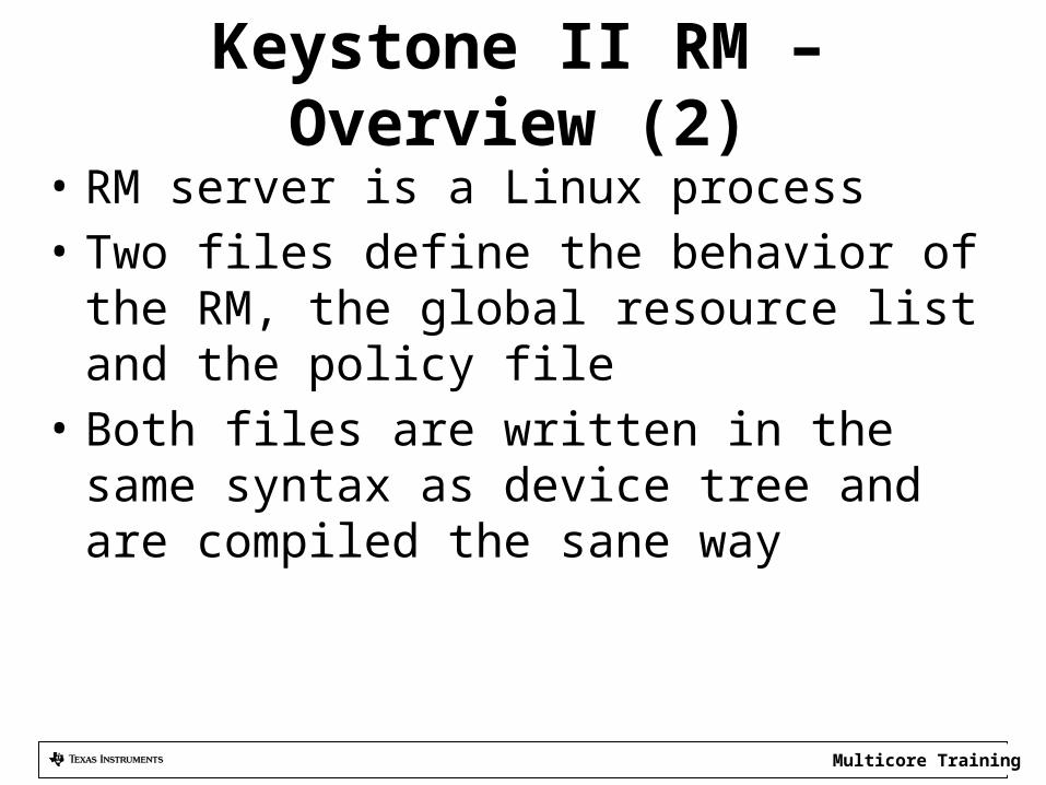
Keystone II RM – Overview (2)• RM server is a Linux process• Two files define the behavior of the RM, the
global resource list and the policy file• Both files are written in the same syntax as
device tree and are compiled the sane way
Multicore Training
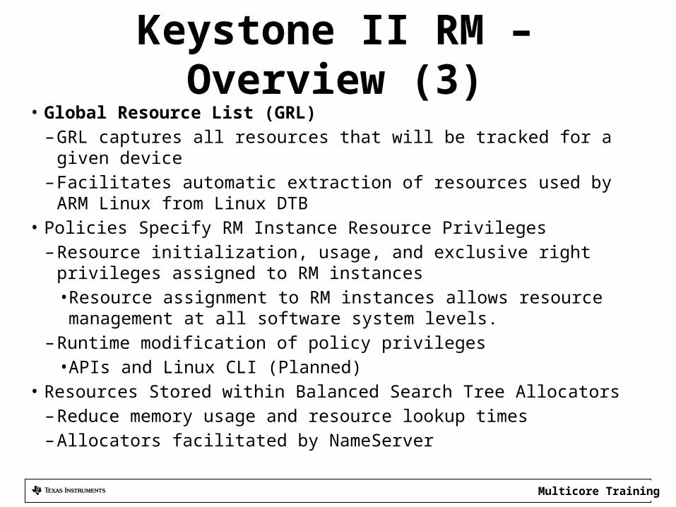
Keystone II RM – Overview (3)• Global Resource List (GRL)
– GRL captures all resources that will be tracked for a given device– Facilitates automatic extraction of resources used by ARM Linux from
Linux DTB• Policies Specify RM Instance Resource Privileges
– Resource initialization, usage, and exclusive right privileges assigned to RM instances• Resource assignment to RM instances allows resource management at
all software system levels.– Runtime modification of policy privileges
• APIs and Linux CLI (Planned)• Resources Stored within Balanced Search Tree Allocators
– Reduce memory usage and resource lookup times– Allocators facilitated by NameServer
Multicore Training
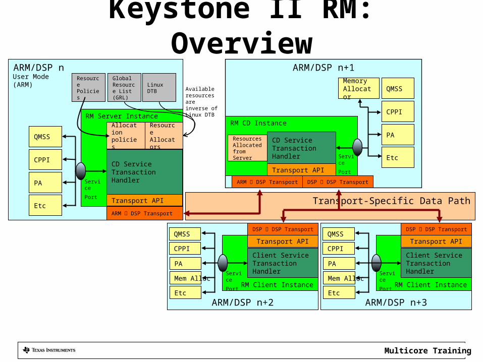
Keystone II RM: Overview
ARM/DSP n+2
RM Client Instance
ARM/DSP n
Transport-Specific Data Path
ARM/DSP n+1
ARM DSP Transport
Transport API
RM CD Instance
Resources Allocated from Server
CD Service Transaction Handler
Client Service Transaction Handler
RM Server Instance
Resource Allocators
PA
QMSS
Allocation policies
CPPI
QMSS
Etc
User Mode (ARM)
Available resources are inverse of Linux DTB
Resource Policies
Transport API
PA
CPPI
QMSS
Etc
Memory Allocator
CPPI
PA
Mem Alloc
EtcARM/DSP n+3
RM Client Instance
QMSS
CPPI
PA
Mem Alloc
Etc
Service
Port
Service
Port
Transport API
Client Service Transaction Handler
DSP DSP Transport DSP DSP Transport
Service
Port
ARM DSP Transport
Transport API
CD Service Transaction Handler
Service
Port
Global Resource List (GRL)
Linux DTB
DSP DSP Transport
Multicore Training
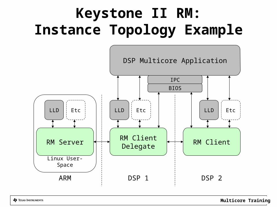
Keystone II RM:Instance Topology Example
Linux User-Space
RM Server RM Client Delegate RM Client
BIOSIPC
LLD
DSP Multicore Application
Etc
ARM DSP 1 DSP 2
LLD Etc LLD Etc
Multicore Training
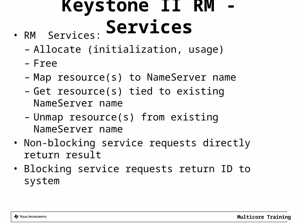
Keystone II RM - Services• RM Services:
– Allocate (initialization, usage)– Free– Map resource(s) to NameServer name– Get resource(s) tied to existing NameServer name– Unmap resource(s) from existing NameServer name
• Non-blocking service requests directly return result• Blocking service requests return ID to system
Multicore Training
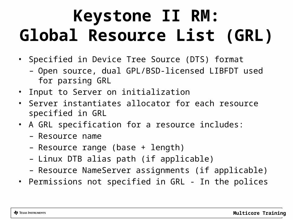
Keystone II RM:Global Resource List (GRL)
• Specified in Device Tree Source (DTS) format– Open source, dual GPL/BSD-licensed LIBFDT used for parsing GRL
• Input to Server on initialization• Server instantiates allocator for each resource specified in GRL• A GRL specification for a resource includes:
– Resource name– Resource range (base + length)– Linux DTB alias path (if applicable)– Resource NameServer assignments (if applicable)
• Permissions not specified in GRL - In the polices
Multicore Training
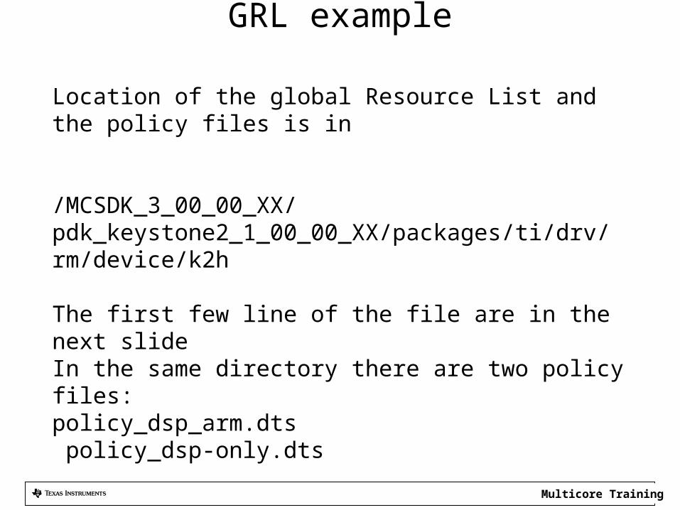
GRL example
Location of the global Resource List and the policy files is in
/MCSDK_3_00_00_XX/pdk_keystone2_1_00_00_XX/packages/ti/drv/rm/device/k2h
The first few line of the file are in the next slideIn the same directory there are two policy files:policy_dsp_arm.dts policy_dsp-only.dts
Multicore Training
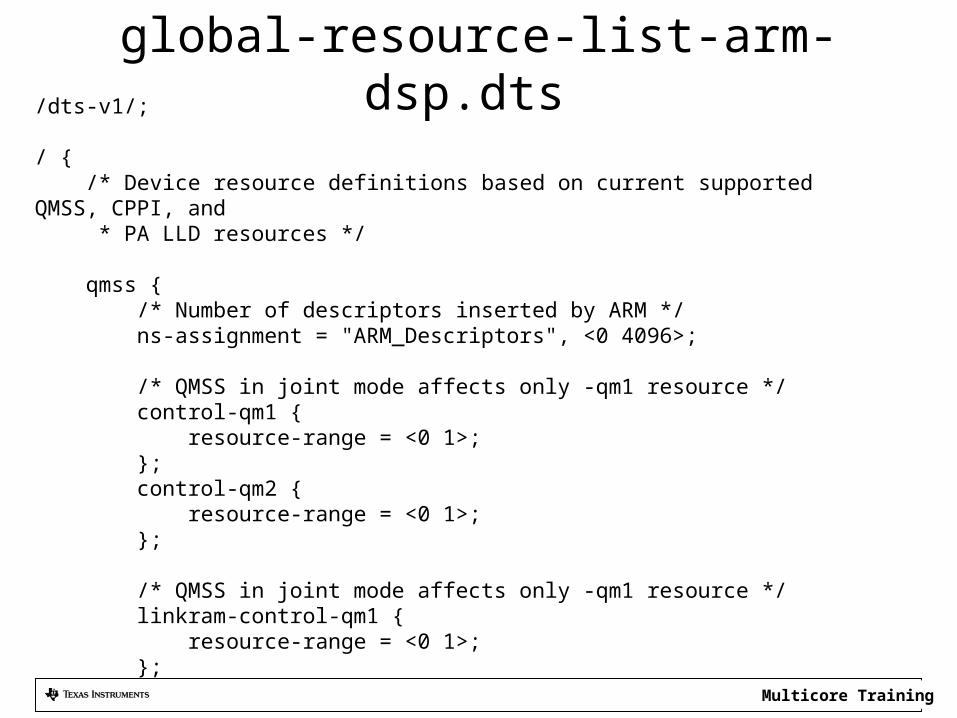
global-resource-list-arm-dsp.dts /dts-v1/;
/ { /* Device resource definitions based on current supported QMSS, CPPI, and * PA LLD resources */
qmss { /* Number of descriptors inserted by ARM */ ns-assignment = "ARM_Descriptors", <0 4096>;
/* QMSS in joint mode affects only -qm1 resource */ control-qm1 { resource-range = <0 1>; }; control-qm2 { resource-range = <0 1>; };
/* QMSS in joint mode affects only -qm1 resource */ linkram-control-qm1 { resource-range = <0 1>; };
Multicore Training
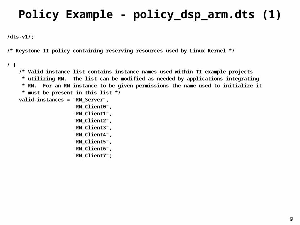
Policy Example - policy_dsp_arm.dts (1) /dts-v1/;
/* Keystone II policy containing reserving resources used by Linux Kernel */
/ { /* Valid instance list contains instance names used within TI example projects * utilizing RM. The list can be modified as needed by applications integrating * RM. For an RM instance to be given permissions the name used to initialize it * must be present in this list */ valid-instances = "RM_Server", "RM_Client0", "RM_Client1", "RM_Client2", "RM_Client3", "RM_Client4", "RM_Client5", "RM_Client6", "RM_Client7";
Multicore Training
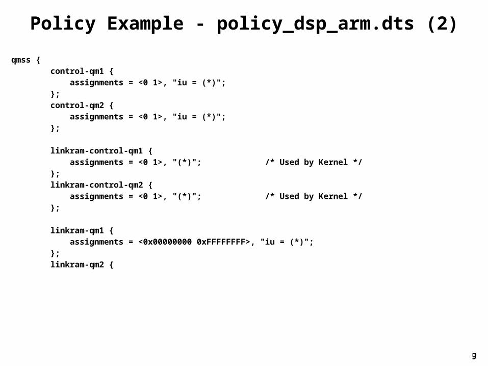
Policy Example - policy_dsp_arm.dts (2) qmss { control-qm1 { assignments = <0 1>, "iu = (*)"; }; control-qm2 { assignments = <0 1>, "iu = (*)"; };
linkram-control-qm1 { assignments = <0 1>, "(*)"; /* Used by Kernel */ }; linkram-control-qm2 { assignments = <0 1>, "(*)"; /* Used by Kernel */ };
linkram-qm1 { assignments = <0x00000000 0xFFFFFFFF>, "iu = (*)"; }; linkram-qm2 {
Multicore Training
Agenda
• Managing the peripherals and IP in hydrogenous device
• Linux Device Tree• Memory Management• Resource Management• ARM-DSP communication Architecture
Multicore Training
ARM-DSP collaboration
• MPM – Managing the DSP cores from the ARM– DSP executables are in the ARM file system– ARM can reset, load, run, and get messages and dump core
out of a DSP core• IPC – exchanging data and messages between ARM
and DSP– User Space libraries: IPC v3, MsgCom, PktIO– Applications that use IPC – OpenCL, openMP– Sockets– openEM
Multicore Training
Multicore Training
IPC Types Overview • Control Path – IPCv3
– Standard APIs agree with older versions of IPC– General purpose control path supports reliable
delivery– Designed to deliver short messages, but can be
used for “unlimited” data movement– Uses RPMSG kernel driver for clean partition
between user and kernel space, Thus slower than data path
Multicore Training
IPC Types Overview
• Fast Path – PktIO and QMSS– On the ARM side, it provides a library netapi that
supports creating, sending and receiving packets from the ARM User space
– Fire and forger (send) polling (ARM) for receive. On DSP, receive is polling , or interrupt or accumulators (using QMSS DLL)
– Navigator based transaction, sending packets (descriptors)
– Low latency, high throughput
Multicore Training
IPC Types Overview
• MsgCom – QMSS based library (User space) – Supports zero copy or PktDMA copy of descriptors– Supports a wide set of communication features
(blocking, non-blocking, interrupt, polling)– Depends on several other component such as
receive agent and job scheduler
Multicore Training
ARM IPC Support
Remote Processor Messaging (RPMsg)RPMsg or Remote Processor Messaging is an open-source friendly Inter Processor Communication (IPC) frameworkSysLinkSysLink is runtime library that provides software connectivity between multiple processors. Each processor may run either an HLOS such as Linux, QNX, etc. or an RTOS such as SYS/BIOS.
Multicore Training
RPMsgThe following are the main features provided by the RPMsg framework:Device Management: Complete life-cycle management of the remote processor cores including the following specific functionalities
Device Initialization - Programming and loading an executable, memory management and powering up the processorPower Management - Runtime power management of the remote processors, putting them into lowest power state (suspend) when not being used activelyTracing - Provide trace logging of code running on remote processorsException Management - Provide information regarding a remote processor fatal errors or exceptionsError Recovery - Reload and reboot the remote processors upon any fatal error or exception
Messaging Framework: A generic Linux messaging architecture/framework with the ability to exchange fixed size control messages with remote processorsResource Management: Request and release peripherals/hardware accelerators for usage by the remote processors, and putting constraints like bandwidth, frequency and latency to meet specific application performance and power requirements
Multicore Training
SysLink
The SysLink product provides the following services to frameworks and applications:Processor ManagerInter-Processor CommunicationUtility modules
Multicore Training
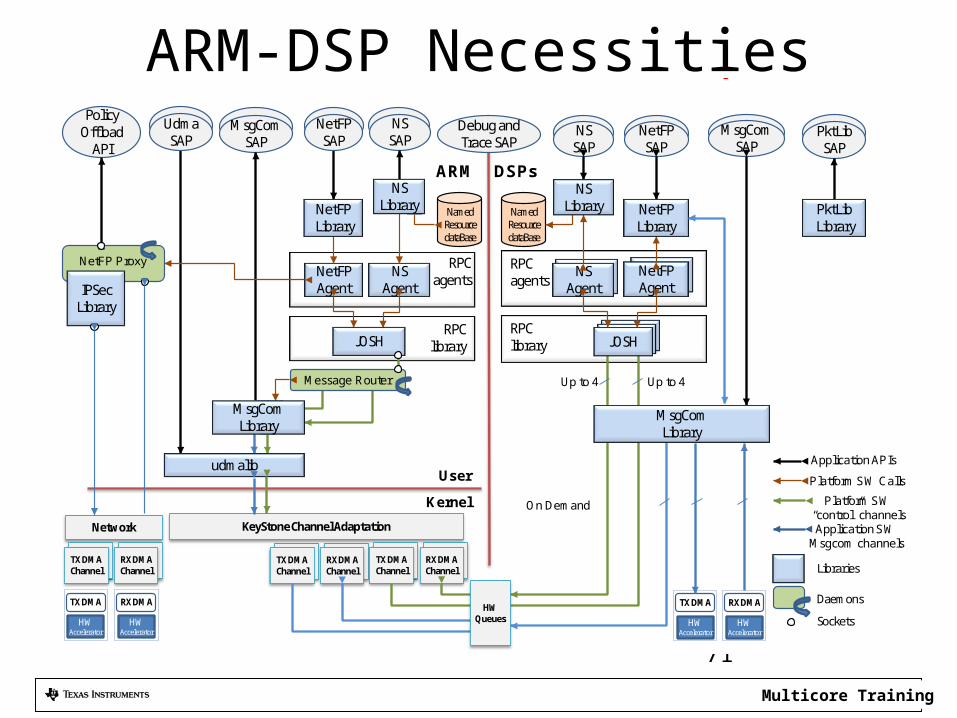
ARM-DSP Necessities
71
RPC agents
PolicyOffload
API
RPC library
RPC library
RPC agents
SC-MCSDK GA Platform Software Components
NSAgent
NetFP Agent
MsgCom SAP
NSAgent
NetFP Agent
NetFPSAP
MsgCom SAP
NSSAP
NetFP SAP
NSSAP
User
Kernel
ARM DSPs
PktLibSAP
Client
Up to 4
NetFP Library
PktLibLibrary
TX DMA Channel
RX DMA Channel
KeyStone Channel Adaptation
Up to 4
On Demand
TX DMA Channel
RX DMA Channel
HW Queues
Application APIs
Platform SW Calls
Platform SW “control” channelsApplication SW
Msgcom channels
NetFP Proxy
IPSec Library
Network
Message Router
NS Library
JOSH
udmalib
MsgCom Library
NS Library
JOSH
TX DMA Channel
RX DMA Channel
TX DMA
HW Accelerator
RX DMA
HW Accelerator
TX DMA
HW Accelerator
RX DMA
HW Accelerator
MsgCom Library
Daemons
Libraries
Sockets
Debug and Trace SAP
UdmaSAP
NetFPLibrary
NamedResource dataBase
NamedResource dataBase
Multicore Training
Msgrouter• Creates special msgcom channels known as
“control channels” or “control path”• Control channel used for system messages and
synchronization purposes• Agent module (later slide) runs consistently
while waiting for messages on these control channels– “ARM created a new data channel, let’s let the DSP
know by sending a message over the control path”
72
Multicore Training
Job Scheduler (JOSH)• Allows function call made on one processing
element to be executed on another processing element
• Defines a prototype for a job/function call• For DSP to understand what ARM is saying (or
vice versa), “execute this particular function on DSP”– Must have common message type
• User application does not directly exercise any of the JOSH APIs
73
Multicore Training
Agent• Module which implements remote procedure
calls between the ARM and the DSP• Main purpose is to sync resources between
ARM and DSP– Utilizes msgcom control path to sync updates
about resources – creation, deletion, modification• Must have separate instance of Agent for each
DSP core being used.
74
Multicore Training
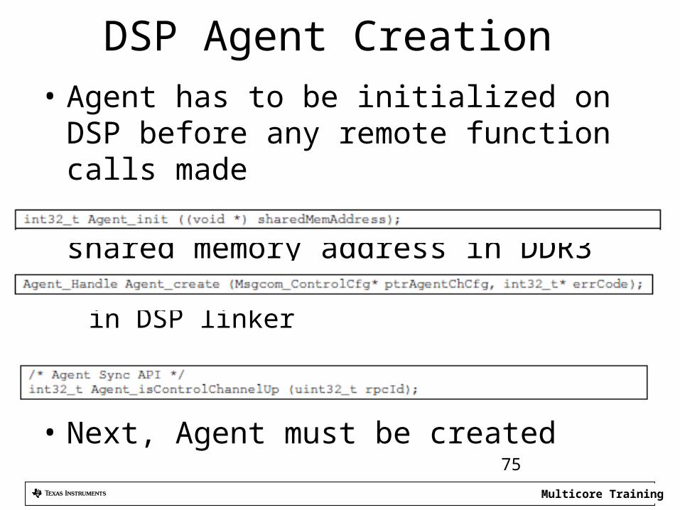
DSP Agent Creation • Agent has to be initialized on DSP before any
remote function calls made• Agent initialization requires a shared memory
address in DDR3– Must reserve 4096 bytes of memory in DSP linker
• Next, Agent must be created
• Finally the Agent must be synced75
Multicore Training
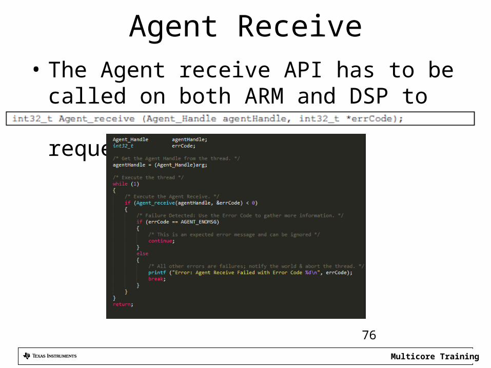
Agent Receive• The Agent receive API has to be called on both
ARM and DSP to receive remote function call requests
76
Multicore Training
For More Information• Software downloads and device-specific Data
Manuals for the KeyStone II SoCs can be found at TI.com/multicore.
• For articles related to multicore software and tools, refer to the Embedded Processors Wiki for the KeyStone Device Architecture.
• For questions regarding topics covered in this training, visit the support forums at theTI E2E Community website.