arib 2020 and beyond ad hoc group white paper 2020 and beyond ad hoc group white paper mobile...
TRANSCRIPT

ARIB 2020 and Beyond Ad Hoc Group
White Paper Mobile Communications Systems
for 2020 and beyond
Version 1.0.0
October 8, 2014
Association of Radio Industries and Businesses (ARIB)

General Notes
1. The copyright of this document is ascribed to the Association of Radio
Industries and Businesses (ARIB).
2. All rights reserved. No part of this document may be reproduced, stored in a
retrieval system, or transmitted, in any form or by any means, without the
prior written permission of ARIB.

ARIB 2020 and Beyond Ad Hoc Group White Paper
Mobile Communications Systems for 2020 and beyond (Version 1.0.0, October 8, 2014)
i
Table of Contents
Scope ................................................................................................................................... 1
1 Introduction .......................................................................................................... 2
2. Objectives ............................................................................................................. 3
3. Market and User Trends of ICT ......................................................................... 4
4. Traffic Trend ........................................................................................................ 7
4.1 Future trend of video data and video traffic ...................................................... 7
4.2 Traffic variation and environmental dependency ............................................. 8
4.3 Mobile traffic growth in the past and future ..................................................... 8
5. Cost Implications ............................................................................................... 12
5.1 Cost analysis of mobile network deployment .................................................. 12
5.2 Cost implication in the 5G era .......................................................................... 12
5.3 Factors contributing to cost reduction of 5G ....................................................... 13
6. Spectrum Implications ...................................................................................... 16
7. Typical Usage Scenarios, General Requirements and Roles of 5G ................ 20
7.1 Typical usage scenarios of 5G ........................................................................... 20
7.2 Impacts of video communications in the 5G era .............................................. 22
7.3 General requirements for 5G ............................................................................ 24
8. Framework and Capabilities of 5G ................................................................... 26
8.1 General ............................................................................................................... 26
8.2 Framework ......................................................................................................... 26
8.3 Maximum capability of 5G from system’s perspective .................................... 27
8.3.1 Quantitatively or qualitatively evolved capabilities from IMT-Advanced
27
8.3.2 Genuine and new capabilities of 5G ......................................................... 30
9. Definition of 5G .................................................................................................. 32
9.1 General ................................................................................................................... 32
9.2 Interworking of 5G RAN ................................................................................... 34
10. 5G Radio Access Technologies .......................................................................... 35
10.1 General ............................................................................................................... 35
10.2 Network architecture(s) .................................................................................... 35
10.2.1 Overall network concept and architecture .............................................. 35
10.2.2 Overview of 5G radio access network ...................................................... 37
10.3 Radio spectrum aspect ....................................................................................... 38

ARIB 2020 and Beyond Ad Hoc Group White Paper
Mobile Communications Systems for 2020 and beyond (Version 1.0.0, October 8, 2014)
ii
11. Conclusion .......................................................................................................... 41
Annex A Functions of 5G Radio Access Technologies ................................................ 42
A.1 General ............................................................................................................... 42
A.2 Technologies to enhance the radio interface .................................................... 45
A.2.1 Advanced modulation, coding and multiple access schemes .................. 45
A.2.2 Multi-antenna and multi-site technologies ............................................. 47
A.2.3 Network densification ............................................................................... 50
A.2.4 Flexible spectrum usage ........................................................................... 51
A.2.5 Simultaneous transmission and reception (STR) ................................... 61
A.2.6 Other Technologies to enhance the radio interface ................................ 63
A.3 Technologies to support wide range of emerging services .............................. 66
A.3.1 Technologies to support the proximity services ...................................... 66
A.3.2 Technologies to support M2M................................................................... 67
A.4 Technologies to enhance user experience ........................................................ 70
A.4.1 Cell edge enhancement ............................................................................. 70
A.4.2 Quality of service enhancement ............................................................... 71
A.4.3 Low latency ................................................................................................ 71
A.4.4 High reliability .......................................................................................... 72
A.4.5 Radio Local Area Network (RLAN) interworking ................................... 72
A.4.6 Context Aware ........................................................................................... 72
A.4.7 Mobility Enhancement with Linear Cell ................................................. 73
A.5 Technologies to improve energy efficiency ....................................................... 73
A.5.1 Network-level power management .......................................................... 74
A.5.2 Energy-efficient network deployment ...................................................... 75
A.5.3 Other item .................................................................................................. 76
A.6 Terminal Technologies ...................................................................................... 76
A.6.1 Advanced receiver...................................................................................... 76
A.7 Network Technologies ....................................................................................... 77
A.7.1 Technologies to enhance network architectures ..................................... 77
A.7.2 Technologies to support ease of deployment and increase network reach
80
A.7.3 Novel RAN architecture ............................................................................ 81
A.7.4 Cloud-RAN (C-RAN).................................................................................. 83
A.7.5 RAN sharing enhancement ....................................................................... 89

ARIB 2020 and Beyond Ad Hoc Group White Paper
Mobile Communications Systems for 2020 and beyond (Version 1.0.0, October 8, 2014)
iii
A.8 Technologies to enhance privacy and security ................................................ 91
A.9 Technical studies on millimeter wave and centimeter wave .......................... 91
A.9.1 Propagation properties in higher frequency bands ................................. 91
A.9.2 Semiconductor technologies for higher frequency bands ....................... 94
Annex B Typical User Throughput ............................................................................. 96
B.1 General ............................................................................................................... 96
B.2 Consideration of deriving Typical User Throughput ...................................... 96
B.3 Related performance requirements and test scenarios specified for
LTE-Advanced (Information for future investigations) .................................. 98
Annex C Roadmap towards 5G .................................................................................. 100
Annex D Provisional Estimate of Video Communication Traffic ........................ 101
References ...................................................................................................................... 103
Terminology, abbreviations .......................................................................................... 112
Change history ............................................................................................................... 116

ARIB 2020 and Beyond Ad Hoc Group White Paper
Mobile Communications Systems for 2020 and beyond (Version 1.0.0, October 8, 2014)
1
Scope
This document summarizes the results of studies on system concepts and technical
trends of mobile communications systems in 2020 and beyond. The study on system
concepts includes market and user trends, traffic trends, cost and spectrum
implications, usage scenarios, requirements and capabilities of mobile communications
systems in 2020 and beyond. As for the study on technical trends, this document
addresses radio access technologies and network technologies of mobile communications
systems in 2020 and beyond.
Although this document mainly addresses radio aspects, non-radio aspects are also
addressed to clearly depict a full picture of mobile communications systems in 2020 and
beyond.

ARIB 2020 and Beyond Ad Hoc Group White Paper
Mobile Communications Systems for 2020 and beyond (Version 1.0.0, October 8, 2014)
2
1 Introduction
Mobile communications systems have been playing prominent roles in the society
over the last couple of decades, and against the backup of the recent boost in mobile
data traffic, they are expected to play even more important roles in the years to come.
This white paper entitled “Mobile Communications Systems for 2020 and beyond" was
developed by “2020 and Beyond Ad Hoc (20B AH)”of Association of Radio Industries and
Businesses (ARIB), Japan to describe vision for the terrestrial mobile communications
systems planned to be commercialized in 2020 and beyond (See Annex C).
The paper first addresses the socio-economic environment surrounding 5G, including
market and user trends, traffic trends, and spectrum implications in the 5G era. It then
identifies the ever increasing roles of 5G and its typical usage scenarios. Cost
implications, which are critical for wide-range deployment of 5G systems, are addressed
in Chapter 5. New capabilities and the framework expected for 5G are shown in
Chapter 8, where the capabilities of 5G are illustrated from a broad perspective, in
particular, in comparison to IMT-advanced systems. Also in Chapter 8, several
diagrams are proposed to address the capabilities of 5G. Then, a definition of “5G” from
the perspective of radio access technologies is proposed in Chapter 9. In Annex A, which
is entitled “5G Radio Access Technologies”, numerous technologies in various categories
required for 5G development are identified.
Throughout the paper, the term “5G” is tentatively used to denote the mobile
communications systems to be commercialized in 2020 and beyond.

ARIB 2020 and Beyond Ad Hoc Group White Paper
Mobile Communications Systems for 2020 and beyond (Version 1.0.0, October 8, 2014)
3
2. Objectives
The primary objective of the paper is to capture agreement on roles and expectations
for 5G and to identify enabling technologies for 5G. The output of the paper will be
made public by taking advantage of various occasions and fora in and outside Japan. It
is also the objective of the paper to send messages and proposals to the industries,
governments, and academia to promote and stimulate 5G development.

ARIB 2020 and Beyond Ad Hoc Group White Paper
Mobile Communications Systems for 2020 and beyond (Version 1.0.0, October 8, 2014)
4
3. Market and User Trends of ICT
In this chapter, overall market and user trends of ICT in the 5G era are addressed
without limiting its scope to the trends of 5G mobile communications systems. In the
subsequent chapters, the discussion will be focused on 5G.
The world today is empowered by information: the opportunities created by ICT
development are one of the main impacting factors on how the society has evolved in the
past decades. Actually, the Internet has become an indispensable tool in everyday life.
It is expected that ICT development will make further progress, resulting in creating
the environment where everything can be done via the Internet in 2020 and beyond. In
other words, the use of ICT will further increase and ICT will be applied to diversified
services.
For example, ICT will be required to deal with a huge amount of data in a wide
variety of applications, thereby fostering innovation in different industries, e.g. M2M,
as shown in Fig. 3-1. M2M will allow wider and efficient deployment of infrastructure
monitoring aimed at disaster prevention, environment conscious and innovative
agriculture with saving water, tailored health monitoring, etc.
Fig. 3-1 ICT dealing with a huge amount of data coming from a wide variety of
applications
ICT will also support flexible life styles, e.g. working, learning, shopping, creating
community and interest groups as shown in Fig. 3-2. Younger generations now use the
Internet for social networking, online gaming/education, and are enjoying/creating
multi-media contents such as movies and music. Future trends of services and

ARIB 2020 and Beyond Ad Hoc Group White Paper
Mobile Communications Systems for 2020 and beyond (Version 1.0.0, October 8, 2014)
5
applications are generally shaped by the evolution of needs of new generations of users
and entailing diversified life styles.
Fig. 3-2 ICT supporting flexible life styles
ICT will also need to address socio-economic requirements, such as disaster
prevention and relief efforts, super-aging society, resource problems, and environmental
problems as shown in Fig. 3-3.
Regarding the disaster prevention and relief efforts, our society has frequently
suffered from natural disasters, such as earthquakes and eruptions. When a wide-scale
disaster happens, infrastructure may be damaged and a huge number of people may
suffer, e.g. losing their houses. Hence, disaster prevention and relief efforts by means of
ICT are strongly demanded in our society.
Regarding the super-aging society, difference between the number of elderly and
younger people is increasing in the developed countries. Fig. 3-4 shows the estimation of
old-age dependency ratio in Japan. In such a society, working-age people will bear
heavy burdens of taking care of elderly people, hence there will be demand for ICT to
ease the burdens in medical/health care and nursing care.
With the increase in population and development of ICT on a global scale, energy
consumption is expected to boost, and it may cause depletion of the underground
resources. Therefore, ICT realized with low power consumption is critical.

ARIB 2020 and Beyond Ad Hoc Group White Paper
Mobile Communications Systems for 2020 and beyond (Version 1.0.0, October 8, 2014)
6
0
10
20
30
40
50
60
70
80
90
100
2015 2020 2025 2030
Rat
io [
%]
Year
Regarding the environmental problems, environmental destruction has still been
observed and we need to prevent further environmental damage. Hence reduction of
emission associated with transportation and electrical power generation is strongly
demanded.
Fig. 3-3 Socio-economic requirements such as disaster prevention and relief efforts,
super-aging society, resource problems, and environmental problems
Fig. 3-4 Estimation of old-age dependency ratio in Japan (Age 65+ / Age 20-64) [1]

ARIB 2020 and Beyond Ad Hoc Group White Paper
Mobile Communications Systems for 2020 and beyond (Version 1.0.0, October 8, 2014)
7
4. Traffic Trend
Over the past few years, there has been significant growth in the volume of mobile
data traffic following the proliferation of smartphones and new mobile devices that
support a wide range of applications and services. There is a general consensus in the
industry that such growth will continue well into the future. Data traffic in super dense
area, such as train stations, stadiums, shopping mall, is expected to become extremely
high. The growth will also be accelerated by new types of communication services and
involved devices, such as proximity services including device-to-device (D2D)
communications and machine to machine communications (M2M).
4.1 Future trend of video data and video traffic
An enhancement of high definition video such as 8K Ultra High Definition (UHD) will
be available around 2020. The number of pixels of visual contents increases accordingly
as shown in Fig. 4-1. The increase in the number of pixels will not be directly translated
into traffic volume, however, impact on traffic volume is inevitable. The provisional
estimate of the total video communication traffic in 2020 carried over mobile and fixed
systems is more than 2600 times the traffic in 2010 (see Annex D). This will have a
certain impact on mobile traffic volume.
Fig. 4-1 Increase in information volume of visual content

ARIB 2020 and Beyond Ad Hoc Group White Paper
Mobile Communications Systems for 2020 and beyond (Version 1.0.0, October 8, 2014)
8
4.2 Traffic variation and environmental dependency
Traffic volume varies greatly depending on time, locations, applications and devices,
and as a result, traffic distribution becomes more and more uneven and not uniform
these days. The trend of traffic non-uniformity will also be prevalent in the 5G era,
when services will be more diversified and require richer contents, and traffic
distribution will become denser. Regarding indoor/outdoor traffic ratio, it is reported
that at least 80% of the total mobile traffic comes from indoor locations [2]. On the other
hand, it is also well known that the indoor/outdoor traffic ratio highly varies depending
on time and locations: outdoor traffic is dominant, e.g. during the daytime as shown in
Fig. 4-2.
Fig. 4-2 Example of indoor/outdoor traffic variation during a day
4.3 Mobile traffic growth in the past and future
Regarding uplink/downlink traffic ratio, downlink traffic would continue to be
dominant in many locations, however, the growth rate of uplink traffic is expected to be
higher than that of downlink traffic, and such trend has been observed recently in
Japan as explained below. In some crowded events such as sporting events and at
concert venues, many photos and video are taken and uploaded simultaneously,
therefore, traffic volume of uplink would be significantly high and may exceed that of
downlink in some cases.
Indoor traffic
Outdoor traffic
0:00 12:00 23:59

ARIB 2020 and Beyond Ad Hoc Group White Paper
Mobile Communications Systems for 2020 and beyond (Version 1.0.0, October 8, 2014)
9
This tremendous increase in the volume of mobile data traffic was not foreseen before
WRC-07. For instance, actual data traffic in 2010 was more than five times greater than
some of the estimates in Report ITU-R M.2072. According to the recent report of MIC
(Ministry of Internal Affairs and Communications) shown in Fig. 4-3-1 to Fig. 4-3-3, the
growth rate of mobile traffic in the past 3 years was around 1.7 per year as a whole and
downlink traffic accounted for nearly 90 percent of the total traffic. Growth rate of
downlink traffic is around 1.7 per year while that of uplink is slightly higher and
around 1.8 per year. The growth rate in busy hour around 23 o’clock also shows a
similar tendency to that of the average traffic growth.
Fig. 4.3-1 Average traffic of mobile communications in Japan [3]

ARIB 2020 and Beyond Ad Hoc Group White Paper
Mobile Communications Systems for 2020 and beyond (Version 1.0.0, October 8, 2014)
10
Fig. 4.3-2 Busy hour traffic of mobile communications in Japan [3]
Fig. 4.3-3 Average traffic per subscriber of mobile communications in Japan [3]
Please note the traffic charts above show the total traffic of mobile data in Japan,

ARIB 2020 and Beyond Ad Hoc Group White Paper
Mobile Communications Systems for 2020 and beyond (Version 1.0.0, October 8, 2014)
11
excluding voice and Wi-Fi traffic.
Based on those mobile data traffic measured in the past, future traffic growth can be
predicted as shown below.
Fig. 4.3-4 Mobile data traffic growth forecast for 2020 and beyond - Example
Fig. 4-3-4 is an example of future mobile data forecast which takes into account both
uplink and downlink traffic derived from the past statistics. In this chart, annual
growth rates of the data traffic of 2.1 and 1.5 times are assumed, corresponding to an
aggressive scenario and a conservative scenario respectively, which were actually
observed in the last few years. With these assumed rates, the 1,000-fold traffic from
2010 will be reached in the timeframe between 2020 and 2025.

ARIB 2020 and Beyond Ad Hoc Group White Paper
Mobile Communications Systems for 2020 and beyond (Version 1.0.0, October 8, 2014)
12
5. Cost Implications
5.1 Cost analysis of mobile network deployment
Despite huge growth of data traffic predicted for the coming future, the average
revenue per user (ARPU) will not increase so drastically in the 5G era as compared to
those in the previous generations. Therefore the total operational revenue is not likely
to grow in proportion to the pace of 5G network expansion aiming to satisfy a wide
variety of market needs including increased data traffic. In view of this background,
cost reduction is one of the key factors in 5G network deployment.
Cost associated with mobile network deployment is roughly divided into two
categories: capital expenditures (hereafter called CAPEX) and operational expenditures
(hereafter called OPEX). According to the past experience in the previous generations,
CAPEX and OPEX can be broken down into elements as shown below.
CAPEX
Equipment cost
- Radio equipment (hardware and software)
- Supplementary equipment (i.e. batteries, air conditioner, transmission equipment,
cubicles, etc.)
Construction cost
- Network planning
- Site acquisition
- Civil works
Construction cost is the dominant part, and equipment cost represents only a fraction
of CAPEX.
OPEX
Site rental fee
Electricity
Operation and Maintenance
Backhaul and front haul cost
5.2 Cost implication in the 5G era
At present, a large portion of capital expenditure associated with radio access
network deployment is attributed to construction cost. As shown in the next section, as

ARIB 2020 and Beyond Ad Hoc Group White Paper
Mobile Communications Systems for 2020 and beyond (Version 1.0.0, October 8, 2014)
13
a result of emerging new technologies, downsizing of base stations using small cells and
mass production, it is expected that equipment cost will go down. Reduction of
construction cost will be increasingly important as well in the 5G era.
Therefore, every effort from a variety of perspectives should be made to minimize the
construction cost. For example, in the U.S., there are wireless providers and companies
that build cell phone towers, rooftop wireless sites, and other facilities required for radio
access network deployment to be shared among mobile operators.
5.3 Factors contributing to cost reduction of 5G
The following are the factors which will have potential impact on CAPEX and/or
OPEX reduction in the 5G systems. The individual impact on each factor will be
referred to in the technology part of this white paper.
- Network Function Virtualization (NFV) of core and radio access networks.
- Global harmonization of spectrum
- Global compatibility of features and equipment (infrastructure and handsets).
- Mechanism to reduce construction cost including, but not limited to sharing of
infrastructure.
- Flexible utilization of equipment including resource pooling.
- Smart OAM systems enabling the reduction of human resources required for
network operation.
- Downsizing of base stations leading to less construction cost, less construction time
and less space.
- Energy saving schemes for both infrastructure and handsets.
- Offloading of traffic to less costly network wherever available.
The following table shows potential elements which may contribute to cost reduction
in the 5G radio networks. It should be noted there may be trade-off among these factors
in terms of influence on OPEX and CAPEX. For more accurate description, detailed
analysis would be required.

ARIB 2020 and Beyond Ad Hoc Group White Paper
Mobile Communications Systems for 2020 and beyond (Version 1.0.0, October 8, 2014)
14
Table 5-1 Potential enablers for cost reduction
Key enabler Contribution
factors Description Cost Impact
MASS-SCALE
MERIT
Support of
major hit
applications
offered in
worldwide
market
*Capability of supporting
popular applications (e.g. OTT,
SNS, Multimedia) and common
features for massive sales and
mass-production for
mega-markets.
* A large scale of production
and sales contributes to
lowering the unit price.
(CAPEX)
Global
Compatibility
* Global standards and open
interfaces will facilitate common
design and inter-operability.
* Manufacturing cost will be
reduced by scale of economy.
(CAPEX)
* Open standards and open
interfaces facilitate
inter-operability and easy
roaming among
multi-vendor systems
without complicated
conversion. (CAPEX)
* Device conformance to the
operation bands identified by
3GPP and ITU-R.
*Manufacturing cost of the
radio devices will be reduced
by scale of economy if the
bands are harmonized.
(CAPEX)
SCALABLE
& OPTIMAL
CONTROL
Scalability
* Capability to adjust capacity in
a scalable manner according to
variation of data volume and
nature of traffic.
* System capability of
scalable operation for
accommodating required
volume of data traffic and
transport demands will help
in reducing cost of
communication
systems.(CAPEX, OPEX)
Optimal control
*Dynamic control/adjustment of
system configuration parameters
(e.g. transmission bandwidths,
channels and transmission
power) based on services and
occasions.
* Tuning for optimal
processing of variable data
and signaling can save
required resources and
operation cost.(OPEX)
NETWORK
VIRTUALIZA
TON
Resource
sharing
*Functions of multiple nodes and
multiple units will be realized by
a common platform.
* The shared structure will
reduce total cost compared
with the case of discrete
structure. (CAPEX)
Flexible
deployment
*Software-based virtual
processing scheme has the
capability of flexible and
controllable operation and
management.
* Small start, timely
roll-out, agile change of
system configuration will be
available.(CAPEX)
*Operational flexibility with
virtualized entities
supporting variable traffic
and diverse services will be
available. (OPEX)
CENTRALIZE
D
Centralized
structure
*BBUs pooled in the central site
in conjunction with the
*Required space for multiple
cell sites will be reduced.

ARIB 2020 and Beyond Ad Hoc Group White Paper
Mobile Communications Systems for 2020 and beyond (Version 1.0.0, October 8, 2014)
15
Key enabler Contribution
factors Description Cost Impact
CONTROL transceivers and antenna system
placed in distributed cells.
*The operation can be controlled
by a central processor.
(CAPEX)
* Total electric power
required for BBU operation
and air-conditioning will be
reduced. (OPEX)
Central control
and
management
*Comprehensive control of
pooled BBU, remote transceivers
and antenna system under the
central brain with a consistent
policy and management.
*Integrated control with the
reasonable set of resources
and the minimum power
operation result in reduction
of operational cost. (OPEX)
Smart OAM
*Central station covers and
conducts radio network
operation, call monitoring, and
maintenance in an intelligent
manner.
*System operation,
maintenance and
trouble-shooting can be
conducted in a timely
manner with minimum
resources.(OPEX)
RADIO
STATIONS
Wireless
connections
*Non-wired free camping of radio
stations and mobile terminals for
radio networking, including
nomadic stations for advanced
D2D and wireless backhaul.
*Autonomous plug-&-play by
advanced SON.
* Agile construction with no
wire-line and the flexible
rollout will reduce
construction cost. (CAPEX)
Down Sizing
*Compact base station
equipment installable in a
limited space.
*Saving of site space,
construction cost, and
consumption power will be
achieved. (CAPEX and
OPEX)
RADIO
DEVICES
Semiconductor
device and
module
technologies for
higher
frequency
*Development of innovative RF
devices (e.g. GaN, InP, GaAs,
SiGe, CMOS ) and module
technologies for transceiver, PA,
LNA, antenna to realize higher
efficiency with smaller size,
higher integration and
longer-life operation in higher
frequency bands (mmWave)
*Cost reduction of such RF
devices and modules will be
one of the key factors.
(CAPEX and OPEX)
MULTI-RAT
INTERWORK
RATs
Interworking
*5G interwork with the existing
radio access infrastructure (e.g.
3G, 4G, and RLAN) which
satisfies requirements for the
systems of previous generations.
* Interwork with the
previous generation
system(s) may lead to
saving the 5G deployment
cost. (CAPEX)

ARIB 2020 and Beyond Ad Hoc Group White Paper
Mobile Communications Systems for 2020 and beyond (Version 1.0.0, October 8, 2014)
16
6. Spectrum Implications
As can be seen from Fig. 6-1, total radio spectrum bandwidth for UMTS/LTE (FDD) in
Japan has been expanding steadily, which reflects rapid growth of traffic over the
mobile communication systems and the results of every effort in satisfying the market
demand. In the meantime, the number of logical frequency bands specified in 3GPP has
also been increasing (see Fig. 6-2) as a consequence of worldwide explosion of
UMTS/LTE.
Fig. 6-1 Radio spectrum bandwidth of UMTS/LTE used in Japan [4]
Fig. 6-2 The number of logical frequency bands specified in 3GPP [4]
Although both the gross total spectrum bandwidth identified for UMTS or LTE and
the number of logical frequency bands in 3GPP have been increasing in a steady
manner, it should be noted that some of these logical frequency bands specified in 3GPP

ARIB 2020 and Beyond Ad Hoc Group White Paper
Mobile Communications Systems for 2020 and beyond (Version 1.0.0, October 8, 2014)
17
overlap each other due to similar but not exactly the same frequency arrangements in
each region or nation. This would imply that the systems now have a variety of
frequency arrangements and that spectrum allocation is diversified or could be
segmented.
Since the component carrier frequency bandwidth of UMTS was set as 5 MHz (or at
most 20 MHz in LTE), most of the frequency bandwidths of one logical frequency band
of UMTS (or LTE) are set around a few 10MHz as shown in Fig. 6-3. Accordingly,
‘Carrier Aggregation’ technology is being developed in 3GPP which aggregates
component carriers and provide wider radio communication links to the users.
It can also be observed in Fig. 6-4 that frequency bandwidth of each frequency band
correlates to its carrier frequency. The higher the carrier frequency, the wider
bandwidth is available.
Fig. 6-3 Bandwidths of logical frequency bands specified in 3GPP [4]

ARIB 2020 and Beyond Ad Hoc Group White Paper
Mobile Communications Systems for 2020 and beyond (Version 1.0.0, October 8, 2014)
18
Fig. 6-4 Bandwidths and carrier frequency of logical frequency bands [4]
Considering the required capacity to satisfy the future traffic demand towards 2020
and beyond, the current frequency spectrum used for mobile communications systems is
not sufficient, and thus wider range of frequency spectrum should be efficiently utilized
in the 5G era, ranging from the existing lower frequency bands to the future higher
frequency bands, e.g., up to millimeter waves. Formerly, such higher frequency bands,
e.g. beyond 6 GHz, were not considered for the mobile communications systems due to
their propagation characteristics. However, technical evolution in the 5G era such as
combined usage of the lower and higher frequency bands will make such higher
frequency bands useful, and thus such higher frequency bands and related technologies
should be investigated for the future mobile communications systems.
Lower frequency bands, e.g., below 6GHz, will continue to be important also in the 5G
era to provide basic coverage and mobility. In the future, wider spectrum bandwidths
are generally required considering the future traffic demand in the mobile
communications systems. Furthermore, the current frequency assignment is highly
fragmented with multiple spectrum chunks over multiple frequency bands. Therefore,
refarming of the existing spectrum allocations should be considered to enable utilization
of wider contiguous spectrum as much as possible in the lower frequency bands.
On the other hand, higher frequency bands, e.g. beyond 6 GHz, also need to be
investigated for future mobile communications systems to utilize much wider

ARIB 2020 and Beyond Ad Hoc Group White Paper
Mobile Communications Systems for 2020 and beyond (Version 1.0.0, October 8, 2014)
19
contiguous frequency spectrum since the bandwidths that can be obtained in the lower
frequency bands are fundamentally limited. It is also desirable that future new
spectrum bands in higher frequency are globally harmonized as much as possible to
avoid possible market fragmentation and implementation complexity. In order to use
unpaired frequency bands efficiently, new duplex schemes beyond the conventional ones
are also of interest.

ARIB 2020 and Beyond Ad Hoc Group White Paper
Mobile Communications Systems for 2020 and beyond (Version 1.0.0, October 8, 2014)
20
7. Typical Usage Scenarios, General Requirements and Roles of 5G
7.1 Typical usage scenarios of 5G
Fig. 7-1 shows typical usage scenarios of 5G.
From the socio-economic perspective, 5G will enhance user satisfaction for existing
services. Navigation and autonomous driving provide more efficient and safer
transportation. Richer contents such as multiuser UHD teleconferences, videos, music,
and books are distributed over 5G networks. Home security and remote control of
consumer electronics realize safe and comfort life. Collision avoidance and rescue from
distress and accidents reduce the number of victims. Distance learning and virtual
experience redress regional disparities of education. Prediction technology for disaster
using M2M networks and robust infrastructure support the disaster relief. Remote
medical examination provides routine preventive care.
In addition to the enhancement of user satisfaction for existing services, 5G induces
completely new use cases as shown in Fig. 7-2. Smart citizen services realize knowledge
creation and activity support. Shared experience provides virtual and perceptual
touches with fidelity, reality and tactile sense. Automatic information sharing in
proximity assists communication between unacquainted persons.
Fig. 7-1 Usage scenarios from socio-economic perspective
Disaster relief Prediction
Robustness to disaster
Health careRemote medical
examination
Richer contents Multiuser UHD teleconference,
Purchase enriched video, music, book
HouseHome security
TransportationMore efficient and safer
NavigationAutonomous driving
5G will enhance the
socio-economic
satisfaction
Safety and lifeline systemCollision avoidanceRescue (Distress, Accident, etc.)
EducationDistance learning
Virtual experience
Consumer electronicsRemote control

ARIB 2020 and Beyond Ad Hoc Group White Paper
Mobile Communications Systems for 2020 and beyond (Version 1.0.0, October 8, 2014)
21
Fig. 7-2 Completely new use cases of 5G
Table 7-1 summarizes reasons why each usage scenario requires wireless access and
the general requirements for 5G in terms of the difference from IMT-Advanced.
Table 7-1 Usage scenarios and their general requirements for 5G in terms of the
difference from IMT-Advanced
Usage scenarios Reasons why the usage
scenario requires wireless access
General requirements for 5G (In terms of difference
from IMT-Advanced)
Transportation (More efficient
and safer, Navigation,
Autonomous driving)
More efficient/safer navigation
and autonomous driving will be
realized by the communication
on vehicle to vehicle and vehicle
to roadside equipment.
For reliable connection, low
latency, mobility, and
guaranteed connectivity will be
required. Safety and lifeline
system(Collision avoidance,
Rescue)
Richer contents
(Multiuser UHD
teleconferences, purchase
enriched videos, music, books)
Richer contents such as videos,
music, books, and multiuser
UHD teleconferences will be
provided in the mobile
environment.
Considering two way
communication, not only
downlink capacity but also
uplink capacity should be
increased.
House (Home security) Many sensors and controllers
will be installed in home
equipment. Due to the difficulty
in wiring, such equipment tends
to have a capability of wireless
connection.
High density connectivity.
Consumer electronics
(Remote control)
Education (Distance learning
Virtual experience)
Distance learning and virtual
experience will be provided on
wireless communication in the
developing regions/countries.
Capacity and peak data rate are
required to support rich
contents.
Assist communication between unacquainted personsShare information in proximity
Smart citizen servicesKnowledge creationActivity support
Share experienceMore fidelity, realisticTactile

ARIB 2020 and Beyond Ad Hoc Group White Paper
Mobile Communications Systems for 2020 and beyond (Version 1.0.0, October 8, 2014)
22
Usage scenarios Reasons why the usage
scenario requires wireless access
General requirements for 5G (In terms of difference
from IMT-Advanced)
Health care Sensors capturing physical
conditions will upload the data
to the server via wireless
connection.
Data on physical conditions
need to be uploaded anytime
and anywhere. Hence
connectivity is important.
Disaster relief (Prediction,
Robustness to disaster)
Smart citizen services
(Knowledge creation, Activity
support)
Utilizing real-time knowledge
created/derived from next
generation hypermedia data,
context relevant services are
provided everywhere. Services
would include support of
business, social, health, sports,
environment, and safety critical
applications.
Note: 'Citizen' here is used in its
broadest sense and includes
human and associated objects.
Large capacity, high density,
and highly dependable
ubiquitous access are required
for mass usage. Interactive
context relevant to real-time
hypermedia services require low
latency.
Share experience (More fidelity,
realistic
Tactile)
Tourists can share their
experience during the travel
with their family and friends in
real time.
Capacity and peak data rate
will be required to transmit rich
contents including videos,
sound, smell, and taste.
Assist communication between
unacquainted persons
Mobile devices automatically
exchange personal information
over wireless connection, then
the terminals search common
experience, hobbies, and
friends.
Low latency will be required to
assist human communication.
7.2 Impacts of video communications in the 5G era
Today, ICT supports entertainment such as video streaming that can be viewed
anytime, anywhere. In the 5G era, such entertainment will provide higher definition
videos than today’s 2K broadcasting. Since television will support 4K/8K beyond 2020,
4K/8K video streaming will also be needed. The following transmission rates should be
supported for each format in case High Efficiency Video Coding (HEVC) is used for
video streaming as in 4K/8K broadcasting.
40 Mbps for 4K (60 fps)
48 Mbps for 4K (120 fps)
100 Mbps for 8K (60 fps)
120 Mbps for 8K (120 fps)
In the meantime, ICT will also support Virtual Reality (VR) which will greatly
enhance user experience with its imaging techniques. For instance, VR will be able to

ARIB 2020 and Beyond Ad Hoc Group White Paper
Mobile Communications Systems for 2020 and beyond (Version 1.0.0, October 8, 2014)
23
virtually take a user anywhere in the world. Scenery captured by image sensors
installed at various places in the world will be transmitted through the mobile networks
and will be displayed on a head mounted display (HMD). Consequently, users will
experience the views as if they were on the spot.
Fig. 7-3 Enhancement of user experience (virtual trip)
In order to realize virtual trips with reality, resolution of at least 8K with 120 fps is
required. In the case of 3D, required information rate will be twice as high as that of 2D.
Therefore, the data rate of 240 Mbps should be supported by the mobile networks if an
image of the whole celestial sphere is to be transmitted. If an image of the desired spot
can be projected in a relatively short time, an image of the half celestial sphere may be
sufficient instead of the whole celestial sphere image. In this case, the data rate of 120
Mbps is required and the time delay should be minimized so that the view projected on
HMD will be in accordance with the movements of the user’s eyes. The HMD requests to
send the image calculated from the angle that the sensor (e.g. gyro, accelerometer) in
the HMD senses according to the movement of the person’s eyes. Then, the remote
cameras on the spot of interest will capture the new images and send them back to the
HMD. Clearly, this process will cause some processing delay. In order to improve users'
perception, the image should be displayed on the HMD within around 8 ms after the
movement of the user’s eyes. In practice, a maximum delay of 12 ms may be tolerable
since the use of predictive algorithms can potentially provide a 4 ms margin. The
non-network-related delay contributions in the current technology can be summarized
as follows:

ARIB 2020 and Beyond Ad Hoc Group White Paper
Mobile Communications Systems for 2020 and beyond (Version 1.0.0, October 8, 2014)
24
camera 4 ms
encoder and server 2 ms
decoder 1 ms
attitude sensor 1 ms
display 2 ms
10 ms total
Therefore, it should be noted that for satisfying the total end to end requirement of 12
ms, the delay budget of network and data processing is critical and requires attention.
7.3 General requirements for 5G
In the 5G era, many new application services are expected to emerge to satisfy diverse
needs and requirements of users by leveraging innovative multimedia applications and
telecommunication technologies.
Fig. 7-4 indicates that, from users’ perspectives, required capabilities vary depending
on applications. Four typical applications are used to illustrate the different capabilities
required by respective application.
(i) Video streaming
(ii) Virtual reality
(iii) M2M communication (i.e. sensors)
(iv) Autonomous driving (i.e. collision avoidance)
As users’ requirements differ depending on applications, the network does not
necessarily have to exhibit maximum performance capabilities, instead, the network
resources should be used efficiently depending on applications.

ARIB 2020 and Beyond Ad Hoc Group White Paper
Mobile Communications Systems for 2020 and beyond (Version 1.0.0, October 8, 2014)
25
Fig. 7-4 Diversified required capabilities from users’ perspectives depending on
applications

ARIB 2020 and Beyond Ad Hoc Group White Paper
Mobile Communications Systems for 2020 and beyond (Version 1.0.0, October 8, 2014)
26
8. Framework and Capabilities of 5G
8.1 General
This chapter first shows a diagram that highlights the difference of capabilities
between 5G and IMT-Advanced/Enhanced IMT-Advanced. Then shows another
diagram that describes maximum system capabilities of 5G. In the latter diagram, the
capabilities consist of those quantitatively or qualitatively evolved from IMT-Advanced
[5] and those genuine and new for 5G.
8.2 Framework
One of the main goals of the 5G systems is to provide better user experience in wider
area with a variety of user densities. Considering this aspect, user experience can be
better represented by ‘Typical User Throughput’ (TUT) than, for example, the peak data
rate. The diagram below illustrates the framework of the 5G systems which is
characterized by ‘Typical User Throughput (TUT) in [bps/device]’ (normalized by that of
IMT-Advanced system in the figure) and ‘User density’ in [device/km2].
TUT represents throughput per user/device under a typical condition, including
user/device density. The typical condition should be set considering reasonable
operation conditions, radio propagation conditions, user density as well as expected
typical deployment of the system (See Annex B).
Typical user throughput can be kept constant for a certain range of user density by
reducing the cell coverage area. It should be noted that the framework provided below
does not restrict any possible deployment in practice, therefore, potentially, the 5G
systems have the ability to provide higher user throughput to its users than what is
illustrated, depending on the deployment conditions.
The following are the three main areas where the capabilities should be enhanced by
5G compared with that of IMT-Advanced;
(i) Coverage expansion in isolated areas, i.e. in rural areas or on a ship distant from
land etc.
In the 5G era, it is essential to offer services in isolated or extremely sparsely
populated areas in a more cost effective manner than IMT-Advanced. The result of the
study carried out by MIC of Japan [6] indicates that dead zones of the existing mobile
phone services in Japan will be halved by 2017, however, approx. 17,000 subscribers
will still remain to be in the ‘out of service’ area. The 5G systems should cope with this

ARIB 2020 and Beyond Ad Hoc Group White Paper
Mobile Communications Systems for 2020 and beyond (Version 1.0.0, October 8, 2014)
27
coverage issue and provide stable and secure services.
(ii) Typical User Throughput improvement
In 5G RAT, the maximum available throughput per single radio link should be
increased by a factor of 100. Together with proper deployment and operation of smaller
cells in the system, this improved maximum throughput will lead to improvement of the
typical user throughput as well, compared with that of the 4G systems.
(iii) Capacity augmentation.
When the user density exceeds a certain point, excessive interference from
neighbouring cells would become a limiting factor to the system capacity. To cope with
this capacity degradation, the 5G systems should adopt several technologies to properly
control interference amongst these smaller cells.
Fig. 8.2-1 Framework of 5G RAN
8.3 Maximum capability of 5G from system’s perspective
8.3.1 Quantitatively or qualitatively evolved capabilities from IMT-Advanced
The diagram below describes the maximum system capabilities of 5G in comparison
to that of IMT-Advanced. In the radar chart, six axes are selected, which are most
appropriate to highlight the difference between the two systems. It should be noted that
the chart represents the maximum capability, and each maximum capability element
would be dependent on other capabilities. For example, the maximum number of
connected devices per single cell in 5G would be kept the same as in Enhanced
IMT-Advanced (probable evolution of IMT-Advanced). However, that should be

ARIB 2020 and Beyond Ad Hoc Group White Paper
Mobile Communications Systems for 2020 and beyond (Version 1.0.0, October 8, 2014)
28
available with larger capacity per area than that in Enhanced IMT-Advanced.
Fig. 8.3.1-1 Maximum system capabilities of 5G RAN
Enhancements to the 6 existing capabilities are shown in the radar chart, and their
quantitative comparisons to IMT-advanced are explained below.
Capacity and peak data rate
To accommodate the soaring mobile traffic and increased number of devices in the 5G
era, system capacity needs to be augmented with high peak data rate and massive
device connectivity. The system capacity of 5G should be approx. 1000 times, in terms of
bit/s/km2, than that of IMT-Advanced. The peak data rate for 5G should be more than
10 Gbit/s while it is approx. 1 Gbit/s for IMT-Advanced. 5G needs new RAT(s) to realize
such a very high peak data rate.
Number of connected devices
Massive device connectivity by the Internet of Things will emerge in the 5G era. It is
forecasted that an increased number of devices, especially M2M sensors and actuators
will be installed on top of the user handsets toward 2020 and beyond. According to some
analysis [7], some tens of billions devices are estimated in the world in 2020, which
would be higher than the number of world population. The number of connected devices
for 5G can be approx. 100 times than that for IMT-Advanced. Enhanced IMT-Advanced
might be able to accommodate such very large number of connected devices [8].

ARIB 2020 and Beyond Ad Hoc Group White Paper
Mobile Communications Systems for 2020 and beyond (Version 1.0.0, October 8, 2014)
29
Latency
Some future real-time applications will impose very short latency. The user plane
latency of 5G should be less than 1 ms while IMT-Advanced requires user plane latency
of less than 10 ms. The definition of user plane latency is the same as that in Subsection
4.5.2 of [5]: “the user plane latency (also known as transport delay) is defined as the
one-way transit time between an SDU packet being available at the IP layer in the user
terminal/base station and the availability of this packet (protocol data unit, PDU) at IP
layer in the base station/user terminal.”
Mobility
Increased traffic demand is expected even in high-speed vehicular environments. 5G
needs to offer higher data rates than IMT-Advanced in the high mobility environments
of approx. 500 km/h. In light of the feasibility study of LTE-Advanced [9], Enhanced
IMT-Advanced is also expected to support mobility of 500 km/h in certain frequency
bands.
Energy efficiency
In order to make 5G a sustainable system, the total energy consumption of 5G should
not significantly exceed that of current RAN. Therefore, energy consumption of 5G in
terms of energy/bit needs to be much smaller than that of today. As for mobile terminals,
5G including new RAT(s) will require less power consumption to realize longer battery
life. The demand for energy efficiency in Enhanced IMT-Advanced is smaller than that
in 5G because of smaller system capacity.
Availability and reliability
Reliability for a certain service can be defined as an ensemble success rate or
possibility to satisfy a set of service requirements at a certain condition. The service
requirements can be user throughput, E2E latency or connection setup time, etc. They
shall be specified depending on each service.
Availability is defined as the ratio of area (and period) in which the reliability or
predefined service requirements are satisfied over the coverage area. The coverage area
for some specific services (i.e. service coverage) could be smaller or larger than that of
other services.

ARIB 2020 and Beyond Ad Hoc Group White Paper
Mobile Communications Systems for 2020 and beyond (Version 1.0.0, October 8, 2014)
30
In the 5G era, ICT will play a role of lifeline systems, providing many services in daily
life as well as during emergency. Examples of availability and reliability for certain
capabilities are listed below.
Availability of 99.999% (almost 100%) to satisfy ultra-low E2E latency
requirement (e.g. less than 10 ms with the probability of 99.9% for each data
transmission) in the coverage area dedicated to ultra-reliable M2M services
such as drive assist and control of automobiles. Obviously such mission-critical
systems should be fail safe and need to have room to tolerate delay to
guarantee ultra-high safety even if the delay requirement is not met.
Availability of 99.9% to satisfy the requirement of connection recovery in
serious disasters (e.g. recovery within one hour after the disaster occurs) in
order to discover and contact disaster victims at the early stages.
Availability of 99% to satisfy the basic throughput requirement (e.g. 1 Mbps) in
order to provide basic social services for citizens such as e-government.
Availability of 90% to satisfy the high throughput requirement (e.g. 40 Mbps)
in order to provide high-quality video services such as 4K video streaming (see
section 7.2).
The quantitative values above need further studies. Some related information may be
helpful to derive them.
The penetration rate of public water supply is approx. 97.5% in Japan
according to Ministry of Health, Labour and Welfare (MHLW) of Japan [10].
Because both mobile communications systems and public water supply are
fundamental and important lifeline infrastructure, the figure could be used as
a reference in terms of service availability of mobile communications systems.
As a reference of required throughput, IMT-Advanced requires spectrum
efficiency of 0.04 bps/Hz with location probability of 95% in pre-defined
simulation assumption with high-speed environment [9].
As a reference of E2E latency, the allowable latency for pre-cash warning is 20
ms [11].
8.3.2 Genuine and new capabilities of 5G
In addition to the enhanced capabilities from IMT-Advanced, 5G needs to have totally

ARIB 2020 and Beyond Ad Hoc Group White Paper
Mobile Communications Systems for 2020 and beyond (Version 1.0.0, October 8, 2014)
31
new capabilities to satisfy requirements for new sorts of applications. Such totally new
capabilities of 5G are listed below.
Guaranteed connectivity to serve as lifeline system
5G needs to guarantee ubiquitous connectivity regardless of geographical locations.
This can help ICT to be provided to everyone as a lifeline system.
Maximizing quality of experience (QoE)
5G needs to be controlled to maximize user perception considering user’s specific
conditions with limited network resources.
Flexibility to support more diversified application needs
New application services are expected to emerge to satisfy more diverse needs, and
required capabilities from users’ perspectives will vary depending on applications.
Flexible and efficient use of network resources will be needed for 5G.
RAT capability for network virtualization
5G will integrate several radio access technologies (RATs) such as Enhanced
IMT-Advanced and New RAT(s). By employing network virtualization, 5G can realize
flexible and efficient use of network resources including multi-RAT to provide seamless
communication experience to customers.

ARIB 2020 and Beyond Ad Hoc Group White Paper
Mobile Communications Systems for 2020 and beyond (Version 1.0.0, October 8, 2014)
32
9. Definition of 5G
9.1 General
Current IMT-Advanced RAT will continue to be developed as Enhanced
IMT-Advanced by adding some new features for enhancing its capabilities, while
maintaining consistency in provided services to the mobile users, e.g. seamless
geographical coverage. It is, however, foreseen that more and more system capabilities
beyond those of Enhanced IMT-Advanced will be needed for mobile radio systems to
fully satisfy users’ demands in the year 2020 and beyond.
Such capabilities, among others, are listed in the order of priority;
Capacity/User Throughput
Latency
Number of Connections
New RAT(s) will be required to achieve even larger gain than that of Enhanced
IMT-Advanced with one or more emerging extremely high capabilities in a cost-effective
manner, even by sacrificing compatibility and commonality with the IMT-Advanced
system and its enhancements. Multiple New RATs, which will focus on other
requirements, may be required to fully cover the emerging capabilities.
The New RAT(s) will focus on major 5G capabilities, e.g. larger gain in capacity and
user throughput, which Enhanced IMT-Advanced cannot sufficiently provide.
IMT-Advanced has evolved from IMT-2000, which was originally designed to provide
mobile multimedia services by using the frequency ranges around 2 GHz. Its design was
not intended to support such extremely higher capacity and user throughput with wider
and contiguous bandwidth in higher frequency bands. Different design criteria, e.g.
considering implementation complexity of carrier aggregation to support extremely
wider bandwidth and severe phase noise in higher frequency ranges, such as mmWave,
would be required for the design of the New RAT(s). On the other hand, the New RAT(s)
may not focus on the scenarios and applications which Enhanced IMT-Advanced can
sufficiently support. For example, the New RAT(s) may not support an extremely large
cell size, which will require redundant options such as specific radio parameters or
frame formats only for isolated areas and emergency cases. Some broadcast type
services also may not be supported since they are required to guarantee reliability over
the entire coverage area. Furthermore, the New RAT(s) may be optimized to the future
higher frequency bands, e.g. beyond 6 GHz, and thus it would not be suitable for the
frequency ranges around 2 GHz.
5G RAN as a whole will, therefore, be realized by the complementary interworking of

ARIB 2020 and Beyond Ad Hoc Group White Paper
Mobile Communications Systems for 2020 and beyond (Version 1.0.0, October 8, 2014)
33
its constituent RATs; Enhanced IMT-Advanced and New RAT(s), which satisfy all the
requirements foreseen for mobile radio communications in the year 2020 and beyond.
The road towards 5G RAN is depicted in Fig. 9.1-1.
Fig. 9.1-1 Road to 5G
The first version of the New RAT(s) will need to be available in the year 2020, and
they will continue to be enhanced. In 2020, the New RAT(s) will not replace Enhanced
IMT-Advanced, although the future possibility could not be precluded at this time,
ROAD TO 5G
20202014
Evolution
New RAT(s)
IMT-Advanced
Enhanced
IMT-Advanced
5G RAN
Year
IMT-Advanced will
continue to be enhanced
New RAT(s) will emerge to satisfy
the requirements not satisfied by
Enhanced IMT-Advanced
Notes:
- 5G RAN, which satisfies all the requirements identified
in this white paper for 2020 and beyond, consists of New
RAT(s) and Enhanced IMT-Advanced.
- New RAT(s) need to be developed in order to satisfy the
requirements not satisfied by Enhanced IMT-Advanced.
- Enhanced IMT-Advanced is a further enhancement of
IMT-Advanced.

ARIB 2020 and Beyond Ad Hoc Group White Paper
Mobile Communications Systems for 2020 and beyond (Version 1.0.0, October 8, 2014)
34
because replace/not replace depends on technologies’ availability in the future.
9.2 Interworking of 5G RAN
Fig. 9.2-1 depicts interworking of 5G RAN with other radio systems indicated before,
where 5G RAN consists of two RAT groups; Enhanced IMT-Advanced and the New
RAT(s). These two RAT groups independently work but also closely and
complementarily interwork to provide the full capabilities of 5G RAN as a whole. 5G
RAN also interworks with other RATs for users to be optimally and cost-effectively
connected.
Fig. 9.2-1 Interwork of 5G RAN
Other radio systems are IMT-2000 and IMT-Advanced, RLAN [12], or BWA, including
their possible future enhancements.
5G RAN
Enhanced
IMT-AdvancedNew RAT(s)
RLAN
IMT-2000/
IMT-Advanced
BWA
Interworking

ARIB 2020 and Beyond Ad Hoc Group White Paper
Mobile Communications Systems for 2020 and beyond (Version 1.0.0, October 8, 2014)
35
10. 5G Radio Access Technologies
10.1 General
In order to realize the 5G systems, advanced radio access technologies should be
applied. In the following subsections, considerations on network architecture(s) of 5G
and radio spectrum aspects are summarized, which could be the premise to develop 5G
radio access technologies. Candidate radio access technologies to realize the 5G systems
are enumerated in Annex A.
10.2 Network architecture(s)
Novel mobile network architecture will need to be structured to achieve the following:
Massive capacity and massive device accommodation;
Intelligently controlled virtual network to provide scalability and resource
management;
Integrated cloud network computing and aggregation to backhaul;
Interworking with multiple RATs including data offload.
In the following chapters and subsections, some technical measures to achieve above
goals are described as probable solutions.
10.2.1 Overall network concept and architecture
In the 5G era, the mobile telecommunication architecture should be evolved to
provide substantially increased manageability and scalability in addition to
massive-capabilities compared to those in the preceding generations. This can be
achieved through the introduction of a centralized software-based network control
structure for the mobile telecommunication network which supports various services.
At the same time, the legacy network (e.g. 4G or 3G) structure may also be applicable as
long as the expected quality of service, which satisfies the 5G performance
requirements, can be delivered to the users.
Adaptive network solutions will be necessary for accommodating IMT evolution and
innovative air interface technologies. Programmable operation, functional
virtualization and network service technologies will reshape the entire mobile
ecosystem, and 5G will facilitate creation of massive-scale services and applications.
ARIB 2020 and Beyond Ad Hoc Group White Paper
Mobile Communications Systems for 2020 and beyond (Version 1.0.0, October 8, 2014)
36
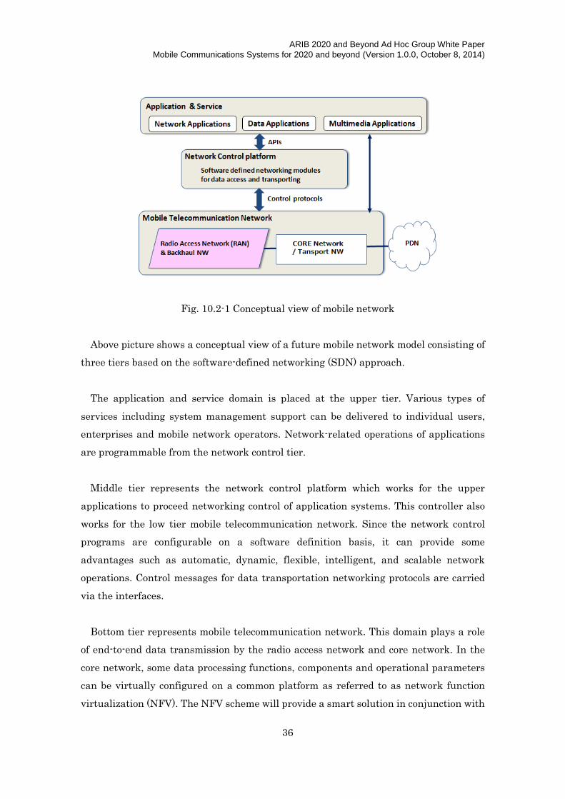
Fig. 10.2-1 Conceptual view of mobile network
Above picture shows a conceptual view of a future mobile network model consisting of
three tiers based on the software-defined networking (SDN) approach.
The application and service domain is placed at the upper tier. Various types of
services including system management support can be delivered to individual users,
enterprises and mobile network operators. Network-related operations of applications
are programmable from the network control tier.
Middle tier represents the network control platform which works for the upper
applications to proceed networking control of application systems. This controller also
works for the low tier mobile telecommunication network. Since the network control
programs are configurable on a software definition basis, it can provide some
advantages such as automatic, dynamic, flexible, intelligent, and scalable network
operations. Control messages for data transportation networking protocols are carried
via the interfaces.
Bottom tier represents mobile telecommunication network. This domain plays a role
of end-to-end data transmission by the radio access network and core network. In the
core network, some data processing functions, components and operational parameters
can be virtually configured on a common platform as referred to as network function
virtualization (NFV). The NFV scheme will provide a smart solution in conjunction with

ARIB 2020 and Beyond Ad Hoc Group White Paper
Mobile Communications Systems for 2020 and beyond (Version 1.0.0, October 8, 2014)
37
the SDN for flexible and optimal network control which are managed by the NFV
operation system.
The approach of software-oriented network and cloud based services will provide the
users with best quality of services (QoS) and experiences (QoE), and will also provide
the operators with reduction of OPEX/CAPEX and energy saving.
10.2.2 Overview of 5G radio access network
The radio access network (RAN) and aggregated backhaul support the capabilities of
data transport, radio transmission and reception. In the 5G era, these capabilities shall
be much more enhanced for accommodating massive traffic capacity and device
connectivity while providing enhanced quality of user experience. Many innovative
technologies mentioned in Annex A will be introduced to improve the performance in
the system for 2020 and beyond. Some of these technologies are illustrated in the figure
below. It should be noted that the technologies in the figure are not exhaustive but just
picked to illustrate some of the probable aspects of these radio access technologies.
Fig. 10.2-2 Radio access technologies for the 5G systems
The 5G RAN coordinates multiple RATs, frequency bands, and heterogeneous
network layers. The coordination can be centralized in the Cloud RAN (C-RAN)
architecture or distributed in the Distributed RAN (D-RAN) architecture. RAN
architectures are expected to be flat and flexible, and may even be virtualized. Cells are
traditionally categorized as Macro, Micro, Pico, and Femto cells depending on the

ARIB 2020 and Beyond Ad Hoc Group White Paper
Mobile Communications Systems for 2020 and beyond (Version 1.0.0, October 8, 2014)
38
coverage radius. New coverage schemes using narrow beams may be considered as well.
The wider radio frequency range including much higher frequency such as mmWave is
used depending on the radio environment and deployment scenarios. The 5G RAN has
the capability of interworking with some earlier generation systems such as 3G and 4G,
and also with other land radio systems such as RLAN and BWA. Additionally,
cooperation with satellite systems can be considered to cover isolated areas, for example.
Some novel radio access technologies will need to be introduced such as new
modulation/coding, interference reduction schemes, advanced antenna systems, flexible
spectrum management. On the mobile terminal side, new network topologies can be
organized among the UE devices, for example, by the enhanced networking of D2D
communication.
10.3 Radio spectrum aspect
Encouraged by the exponential growth of the mobile traffic and the resulting
spectrum exhaustion problem, the mobile industry has continued to make efforts to
drastically improve the network capacity: one such effort is to continue to seek new
spectrum on top of trying to aggregate channels of the already-allocated frequency
bands, i.e. carrier aggregation (CA). Fig. 10.3-1 illustrates examples of corresponding
UE configurations. Configuration on the left-hand side represents a CA-capable UE
which combines component carriers and utilizes wider spectrum bandwidth by
introducing a duplexer. This configuration results in excessive signal losses both in its
transmitter chain and receiver chain, causing increased power consumption and impact
on its physical dimensions. If wider spectrum bandwidth is available as shown on the
right-hand side of the figure, it would provide a simpler UE architecture and more
attractive attributes in terms of performance as well as physical dimensions.

ARIB 2020 and Beyond Ad Hoc Group White Paper
Mobile Communications Systems for 2020 and beyond (Version 1.0.0, October 8, 2014)
39
Fig. 10.3-1 Examples of UE configurations: CA-capable UE and wider single band UE
Given this background, one of the ways to achieve even higher network capacity is to
take advantage of higher frequency bands that have not been considered for cellular
systems in the past. The millimeter waves including centimeter waves, we call in this
white paper “mmWave”, are attracting increased attention of the industry simply
because mmWave has several advantages in terms of 1) system densification due to
shorter range with less interference, 2) bandwidth due to overwhelmingly broader
bands, and 3) spectral efficiency enabled by advanced beam steering and massive
MIMO. Needless to say, even though the use of mmWave is being examined as a
candidate, the UHF bands which have been targeted by cellular services from the
beginning should still be the key bands for the 5G systems.
Radio propagation characteristics have significant impact on the design of the radio
system architecture. Compared to the UHF bands, other than free-space path loss, in
the mmWave bands, further significant attenuation loss factors come into play, such as
absorption losses by molecules of oxygen, water vapor and other gaseous atmospheric
constituents. Millimeter wave propagation characteristics have been studied
extensively for a very long time. Detailed calculations of those atmospheric absorptions
were first published in the 1940s and the CCIR published a report on the topic [13].
As its descendant, ITU-R elaborated a recommendation in [14]. Rain loss depends on
frequency and hourly precipitation as studied in [15]. Foliage losses at millimeter wave
frequencies are also significant [16]. For non-line-of-sight (NLOS), radio wave
propagates via reflection, diffraction or bending. As is the case for light waves, mmWave

ARIB 2020 and Beyond Ad Hoc Group White Paper
Mobile Communications Systems for 2020 and beyond (Version 1.0.0, October 8, 2014)
40
is subject more to shadowing and reflection than diffraction due to the nature of short
wavelength. The short wavelength also causes diffusion at the reflection surface(s).
However, direct reflection is normally the greatest contributor in NLOS [15].
Radio system designs for mmWave should take into account these propagation
characteristics. The basic approach would be to avoid the particular frequency bands in
mmWave which show significantly high attenuation, considering power efficiency both
in base stations and user equipment.

ARIB 2020 and Beyond Ad Hoc Group White Paper
Mobile Communications Systems for 2020 and beyond (Version 1.0.0, October 8, 2014)
41
11. Conclusion
This white paper entitled “Mobile Communications Systems for 2020 and beyond”
was developed by “2020 and Beyond Ad Hoc (20B AH)” of Association of Radio
Industries and Businesses (ARIB), Japan, in order to describe the terrestrial mobile
communications systems to be commercialized in 2020 and beyond.
The paper addressed the socio-economic environment surrounding 5G, including
market and user trends, traffic trends, cost and spectrum implications, as well as the
framework and capability aspects of 5G. Based on the examination on the development
road towards ‘5G’, it was concluded that the radio access network (RAN) for IMT for
2020 and beyond as a whole will be realized by the complementary interworking of its
constituent Radio Access Technologies (RATs), i.e., Enhanced IMT-Advanced and New
RAT(s), which satisfy all the requirements foreseen for mobile radio communications in
the year 2020 and beyond. As for the framework, ‘Typical User Throughput’ is
considered one of the most important measures to characterize IMT for 2020 and
beyond, focused on user experience in the wide range of user density.
Numerous technologies in various categories identified as effective 5G RAT(s)
technologies are summarized in the list in Annex A.

ARIB 2020 and Beyond Ad Hoc Group White Paper
Mobile Communications Systems for 2020 and beyond (Version 1.0.0, October 8, 2014)
42
Annex A Functions of 5G Radio Access Technologies
A.1 General
In the following subsections, candidate radio access technologies to realize 5G system
are enumerated. Table-A.1-1 shows correlation between these candidate radio access
technologies and 5G capabilities described in Chapter 8. It should be noted that in some
cases, those technologies in each section (each row in Table A.1-1) may not support
capabilities marked as ‘x’ but subset of the technologies involved in the section or
combination of them with certain conditions or deployment may support the capability.

ARIB 2020 and Beyond Ad Hoc Group White Paper
Mobile Communications Systems for 2020 and beyond (Version 1.0.0, October 8, 2014)
43
Table.A.1-1 Correlation between 5G RAT and 5G RAN features, capabilities
Feature, Capability
Radio Access Technology
Covera
ge [8
.2 (i)]
Use
r Th
rou
gh
pu
t [8
.2 (ii)]
Pea
k D
ata
Ra
te [8
.3.1
]
Mob
ility [8
.3.1
]
Cap
acity
[8
.2 (III), 8
.3.1
]
Con
necte
d d
evice
s [8
.3.1
]
La
ten
cy [8
.3.1
]
En
erg
y [8
.3.1
]
Ava
ilability
/ Relia
bility
[8.3
.1]
Life
line co
nn
ectio
n [8
.3.2
]
QoE
[8.3
.2]
Ap
plica
tion
div
ersity
[8.3
.2]
Virtu
aliz
atio
n [8
.3.2
]
A.2 Technologies to enhance the radio interface
A.2.1 Advanced modulation, coding and multiple access schemes x x x x x x x x
A.2.2 Multi-antenna and multi-site technologies x x x x x x
A.2.3 Network densification x x x x x x
A.2.4 Flexible spectrum usage x x x x x x x
A.2.5 Simultaneous transmission and reception (STR) x x x x x x
A.2.6 Other Technologies to enhance the radio interface x x x x x
A.3 Technologies to support wide range of emerging services
A.3.1 Technologies to support the proximity services x x x x
A.3.2 Technologies to support M2M x x x x x x x
A.4 Technologies to enhance user experience
A.4.1 Cell edge enhancement x x x x
A.4.2 Quality of service enhancement x x x
A.4.3 Low latency x x
A.4.4 High reliability x x
A.4.5 Radio Local Area Network (RLAN) interworking x x x
A.4.6 Context Aware x x
A.4.7 Mobility Enhancement with Linear Cell x x
A.5 Technologies to improve energy efficiency

ARIB 2020 and Beyond Ad Hoc Group White Paper
Mobile Communications Systems for 2020 and beyond (Version 1.0.0, October 8, 2014)
44
Feature, Capability
Radio Access Technology
Covera
ge [8
.2 (i)]
Use
r Th
rou
gh
pu
t [8
.2 (ii)]
Pea
k D
ata
Ra
te [8
.3.1
]
Mob
ility [8
.3.1
]
Cap
acity
[8
.2 (III), 8
.3.1
]
Con
necte
d d
evice
s [8
.3.1
]
La
ten
cy [8
.3.1
]
En
erg
y [8
.3.1
]
Ava
ilability
/ Relia
bility
[8.3
.1]
Life
line co
nn
ectio
n [8
.3.2
]
QoE
[8.3
.2]
Ap
plica
tion
div
ersity
[8.3
.2]
Virtu
aliz
atio
n [8
.3.2
]
A.5.1 Network-level power management x x
A.5.2 Energy-efficient network deployment x
A.5.3 Other item x x
A.6 Terminal Technologies A.6.1 Advanced receiver x x x x x x x x
A.7 Network Technologies A.7.1 Technologies to enhance network architectures x x x x x
A.7.2 Technologies to support ease of deployment and increase network reach x x x x
A.7.3 Novel RAN architecture x x x x x
A.7.4 Cloud-RAN (C-RAN) x x x x
A.7.5 RAN sharing enhancement x x x x x
A.8 Technologies to enhance privacy and security x x
A.9 Technical studies on millimeter wave and centimeter wave x x x x

ARIB 2020 and Beyond Ad Hoc Group White Paper
Mobile Communications Systems for 2020 and beyond (Version 1.0.0, October 8, 2014)
45
A.2 Technologies to enhance the radio interface
A.2.1 Advanced modulation, coding and multiple access schemes
A.2.1.1 Non-orthogonal multiple access
Future RAN systems must cope with increasing data traffic and a large number of
connected users. It is required to achieve not only high system capacity but also high
user throughput on a macro cell layer which cope with increasing data traffic and a
large number of connected users. The technique employing non-orthogonal multiple
access can achieve to assign radio resources to users immediately even if the radio
resources are occupied by other users. The non-orthogonal multiple access techniques
may employ both power levels and spreading codes in combination as mechanisms to
facilitate the recovery of different data packets transmitted on common resources.
Non-orthogonal multiple access (NOMA)
Non-orthogonal multiple access based on the use of power levels and advanced
receivers has been introduced in [17]. Considering downlink operation with this
technique, multiple downlink signals for different users are superimposed before
transmission on common resources. The signals may be assigned different power levels
to facilitate reception at the user. As for the uplink multiple access, the base station
assigns the radio resources to multiple users so that the uplink signals are
spatially-multiplexed on radio channel. The criteria for paired user selection may
include conditions on the power levels arriving at the uplink receiver.
Interleave Division Multiple Access (IDMA)
Interleave Division Multiple Access (IDMA) is a contention based access scheme in
which very low-rate error control code words are applied and different interleaves are
used to distinguish users. While it has been originally proposed as single-carrier
transmission scheme, multi-carrier IDMA called OFDM-IDMA has been recently
proposed, which successfully combines the advantages of OFDM and has higher
throughput in a multipath environment compared to single-carrier IDMA. IDMA is
suited to transmit small packet because it reduces the amount of require control signals
used for frequency scheduling [18].
Sparse code multiple access (SCMA)
The non-orthogonal multiple access may also be based primarily on spreading codes
[19]. The sparse code multiple access (SCMA) scheme also uses a nonlinear spreading
mechanism, and enables the non-orthogonal superposition technique. In the SCMA,

ARIB 2020 and Beyond Ad Hoc Group White Paper
Mobile Communications Systems for 2020 and beyond (Version 1.0.0, October 8, 2014)
46
FEC encoded binary domain data are directly mapped to sparse complex domain
codewords selected from a predefined codebook set. The codewords are then mapped to
OFDMA resource elements, for implementing the spreading process. Multiple user access
is achievable by the application of codebooks to each layer or user and adding their
respective contribution to the complex vector to be transmitted using the allocated
OFDMA resource elements. A key characteristic of the sparse spreading codes is that
the system resources can be overloaded such that the number of multiplex layers can be
more than the spreading factor. The spreading codes can be optimized for shaping gain
(by maximizing decoding decision distance over multiple dimensions) and can also use
different power on the active tones.
With these non-orthogonal multiple access schemes mentioned above, it is essential to
implement interference cancellation and/or suppression at the receiver in order to
reduce the inter-user interference caused by the non-orthogonally multiplexing. For the
NOMA scheme based on power level multiplexing, non-linear receiver algorithms such as
successive interference cancellation (SIC), turbo equalization (iterative soft interference
cancellation, and so on), are promising candidates to obtain significant non-orthogonal
multiple access gain. For the SCMA, a codeword base MPA receiver can be seen in [19].
The capability of interference cancellation is required for the base station for the
uplink and the user for the downlink to discriminate the desired signals. Moreover, for
further enhancement of user throughput, channel dependent scheduling should be
considered in the three-dimensional domains, i.e. time, frequency, and space.
A.2.1.2 Advanced modulation, coding and Waveform
To cope with the large traffic in the future, there is strong demand to improve the
spectral efficiency. New signal waveform transmission schemes, e.g., Faster-Than
Nyquist (FTN) transmission, Filter Bank Multi Carrier (FBMC) transmission, may be
one of the potential radio access technologies under such an environment. Although the
highly-sophisticated processing is required, some of these schemes may become one of
the approaches with the potentiality to improve the spectral efficiency by increasing the
data rate.

ARIB 2020 and Beyond Ad Hoc Group White Paper
Mobile Communications Systems for 2020 and beyond (Version 1.0.0, October 8, 2014)
47
A.2.2 Multi-antenna and multi-site technologies
A.2.2.1 Multi-antenna technologies
(1) Narrow beamforming in rural area
5G RAN needs to serve very high throughput of users even in rural area. Use of small
cells is able to improve throughput of congested users in urban area, whereas
beamforming is effective to improve throughput of sparsely-scattered users in large cell
coverage of rural area. By using adaptive narrow beamforming, transmission power can
be highly concentrated on small area around static and/or moving user(s). The
technologies to control large number of antenna elements, obtain accurate channel state
information and track moving users are required to be investigated.
(2) Nonlinear precoding MU-MIMO
Multi-user MIMO (MU-MIMO) transmission is one of promising techniques for
improving the spectral efficiency of both macro and small cell. The improvement of
small cell spectral efficiency is mandatory necessary for offloading the large data traffic.
Nonlinear precoding MU-MIMO, e.g., Tomlinson Harashima precoding, Vector
perturbation, is more beneficial for small cell than current linear precoding MU-MIMO
because the transmission performance of nonlinear precoding does not need severe user
pairing required in the linear precoding MU-MIMO. This indicates the nonlinear
precoding MU-MIMO can multiplex a larger number of users than the linear precoding,
therefore, the nonlinear precoding MU-MIMO will successfully deal with the large data
traffic of high load small cell.
Nonlinear precoding MU-MIMO can suppress the inter-user interference by the
linear filtering similar to the current linear precoding. However, before the linear
filtering, the nonlinear precoding can add a perturbation vector to extend the original
constellation of modulation symbol as the multiples of constellation in the infinite
lattice. By selecting the suitable perturbation vector, the transmit power increased by
the linear filtering can be reduced. Any point in the infinite lattice can be recovered in
the original constellation by the modulo operation. Therefore, from the viewpoint of the
receiver algorithms at user terminal side, it is sufficient that each receiver applies the
simple modulo operation to the received signal.

ARIB 2020 and Beyond Ad Hoc Group White Paper
Mobile Communications Systems for 2020 and beyond (Version 1.0.0, October 8, 2014)
48
(3) Narrow-beam antenna
Fig. A.2.2-1 Several-tens elements array antenna
The current state-of-the-art MIMO scheme is typically based on closed loop spatial
multiplexing using PMI (Precoding Matrix Indicator) feedback and SFBC (Space
Frequency Block Code). For Enhanced IMT-Advanced, narrow beamforming using an
antenna array consisting of several tens elements is utilized in a 3D MIMO scenario. In
3D MIMO, a beam pattern is controlled in both horizontal and vertical spatial
dimension to avoid interference from neighboring cells.
(4) Enhanced MIMO for interference cancellation
In addition to the current MIMO scheme, the enhanced MIMO scheme will be
introduced into the base stations and cancel/reduce the interference signal, which can
be realized by analyzing the interference signals from the adjacent base stations and/or
unconnected user equipment to the base station, This will be based on the same
technology which is introduced to the current user equipment as IRS (Interference
rejection combining).
This enhanced MIMO scheme improves not only the receiver sensitivity of the base
stations, but also the system capacity by the reduction of the interference between cells.
This improvement will be particularly effective and useful to solve the interference
issues in the dense deployment of the small cell base stations.

ARIB 2020 and Beyond Ad Hoc Group White Paper
Mobile Communications Systems for 2020 and beyond (Version 1.0.0, October 8, 2014)
49
(5) ABF Cell/Small Massive Antenna
Fig. A.2.2-2 Small Massive Antenna/ ABF Cell
In the development of 5G, it is important to overcome propagation loss in higher
frequency band, and to improve spatial user multiplexing performance for both mobile
and static use cases. A new cell concept, Adaptive BeamForming (ABF) cell, will satisfy
the aforementioned 5G requirements using massive antennas. In the adaptive
BeamForming cell, massive antennas are used to provide flexible beam patterns,
allowing expansion of a cell radius and MU-MIMO with higher capacity. The proposed
cell is also designed for clustered mobile use cases. For example, within the proposed
cell, commuter bus riders can use high data rate services during rush hour.
(6) High speed 3D beamforming
By tracking the narrowed beam very fast to vehicles or trains, very stable and high
throughput communication can be realized in such a fast moving object by using high
speed 3D beam forming. Especially to trains, even if the speed is very fast, the starting
time, starting position and root of tracking can be easily predicted by the information
which includes the time table, rail map and train position offered by the train control
system, if the base stations have the interface to the system and they are well
coordinated. Moreover this coordination will be very useful for the hand over system
between base stations. So it might be more easily installed to the well-controlled trains.

ARIB 2020 and Beyond Ad Hoc Group White Paper
Mobile Communications Systems for 2020 and beyond (Version 1.0.0, October 8, 2014)
50
A.2.2.2 Multi-site technologies
Multi-site technologies with beamforming
Multi-site transmission/reception technologies with beamforming are needed to
prevent link loss due to shadowing and execute smooth handover. In the proposed ABF
cell scenario, UE and a target cell need to find each other to establish a communication
link with an optimize beam pattern. Therefore, UE or target cell search function needs
to be improved or developed.
The technologies shall improve the following performances:
- Probability of handover failure, radio link failure
- Time required optimizing beams
A.2.3 Network densification
To address the challenge of able to provide extremely high traffic capacity and
multi-Gbps data rates in specific scenarios, the introduction of ultra-dense network
deployments is foreseen with nodes operating with very wide transmission bandwidths
in higher-frequency bands relying on new RAT.
• Ultra-dense networks will consist of low-power access nodes being deployed with
much higher density than the networks of today. In extreme cases, we foresee
indoor deployments with access nodes in every room and outdoor deployments with
access nodes at lamppost distance apart. To reliably support multi-Gbps data rates,
ultra-dense networks should support minimum transmission bandwidths of several
100MHz with the possibility of an extension up to GHz-order bandwidth.
• Ultra-dense networks will primarily operate in the high frequency (typically above
20GHz). High frequency bands appear more suitable to the shorter-range
communication of ultra-dense networks. Higher frequency bands make it easier to
provide the very wide transmission bandwidth needed to reliably support
multi-Gbps data rates. Ultra-dense networks will include advanced network
solutions, such as integrated wireless multi-hop self-backhaul and advanced node
coordination.
• Although they will operate in different spectrum and will most likely be based on
new RAT, the ultra-dense networks should be well integrated with the overlaid
cellular networks, providing a seamless user experience as devices move in and out
of ultra-dense network coverage.

ARIB 2020 and Beyond Ad Hoc Group White Paper
Mobile Communications Systems for 2020 and beyond (Version 1.0.0, October 8, 2014)
51
A key technical trend efficiently to deploy dense network is a Phantom cell concept
[20], which is a network architecture concept splitting control (C)-plane and user data
(U)-plane between macro-cell layer and small-cell layer in the overlaid cellular network
using different frequency bands as shown in Fig. A.2.3-1. The C-plane is provided by a
macro cell in a lower frequency band to maintain good connectivity and mobility. The
macro cell also works as a normal cell supporting both C-plane and U-plane signaling.
On the other hand, a broadband U-plane is provided by a small cell using a higher
frequency band in order to boost the capacity and data rate. In the concept, there are
variable motivations to be addressed for practical dense small cell deployments as
follows.
• Small cell deployment without impact on mobility management
• Energy/cost efficient small cell operations
• Relaxing of cell planning effort and backhaul requirements
• Efficient small cell discovery
Phantom cell concept also includes functionality of inter-node carrier aggregation, i.e.,
dual connectivity, to relax the backhaul requirements between macro cell and small cell.
In the 5G era, such network configuration splitting C-plane and U-plane will be the
baseline to integrate future multi-layer networks using lower and higher frequency
bands.
Figure A.2.3-1 Phantom cell concept with C/U-plane splitting.
A.2.4 Flexible spectrum usage
The mobile communication systems have been evolved by adapting new technologies
Existing
cellular bands
Higher
frequency bands
C-plane: Macro cell maintains
good connectivity and mobility
Macro cell
U-plane: Small cell provides
higher data rate and more flexible
& cost-energy efficient operations
Small cell

ARIB 2020 and Beyond Ad Hoc Group White Paper
Mobile Communications Systems for 2020 and beyond (Version 1.0.0, October 8, 2014)
52
to improve their spectrum efficiency, e.g. cellular concept, adaptive modulation and
coding scheme and efficient radio resource management to alleviate the spectrum
demand for mobile communications. Due to the ever increasing demand for mobile data
communications, the spectrum demand is still increasing. The spectrum demand for
mobile communications is forecasted 1000 to 2000 MHz by the year 2020 [21]. Since the
radio spectrum resource is limited and scarce, it is getting more difficult to get new
radio spectrum for mobile communication systems and/or to refarm radio spectrum in
order to assign more spectrum to mobile communication systems within the framework
of current spectrum usage scheme. Schemes and technologies for more “flexible” use of
spectrum need to be developed to satisfy ever-increasing demands for spectrum.
The focus area of R&D is also shifting from the development of spectrally efficient
technologies to that of flexible use of spectrum so that all the spectrum resources
available can be fully exploited.
In the flexible use of spectrum, there are two major categories; (1) flexible spectrum
use retaining the current spectrum regime (Sections A.2.4.1, A.2.4.2 and A.2.4.3) and
(2) flexible spectrum use that needs changes to some extent in the spectrum regime
(Sections A.2.4.4 and A.2.4.5).
In a single RAT, for example LTE, the RAT has conventionally used one of the
multiple frequency bands, e.g. 800-900MHz, 1.5 GHz and 2GHz ranges, which are
assigned to LTE/LTE-Advanced mobile communication systems. Recently, the
technology has been developed so that the RAT can aggregate multiple frequency bands
to obtain a logical broadband radio channel (Carrier Aggregation). In the future, the
RAT will flexibly use/aggregate these frequency bands to fully exploit the different
nature of these frequency bands to achieve higher efficiency of spectrum utilization.
This technology is described in Section A.2.4.1.
The other approach to exploit advantages of the difference of the spectrum band is a
heterogeneous network of different types of RATs, in which multiple RATs are
aggregated as described in Section A.2.4.2. This approach flexibly manages multiple
RATs to achieve high efficient spectrum use by exploiting both the difference of
spectrum bands and systems. The first attempt of this approach has been used for
offloading mobile communication traffic to a Wi-Fi which sometimes less utilizes the
radio spectrum.
The emerging approaches for higher spectrum use are those fall in Flexible Spectrum
Access (FSA) as described in A.2.4.3 to A.2.4.5, in which a focus is brought into

ARIB 2020 and Beyond Ad Hoc Group White Paper
Mobile Communications Systems for 2020 and beyond (Version 1.0.0, October 8, 2014)
53
spectrum sharing with multiple radio communication systems to achieve higher
spectrum usage rate, assuming that some spectrum bands are underutilized depending
on time and geographical areas according to the results of spectrum occupancy
measurements [22] [23]. Section A.2.4.3 addresses the shared use of license-exempt
spectrum bands by mobile RAT such as LTE, which has been operated in frequency
bands exclusive to public land mobile communications. Section A.2.4.4 provides
overview of Dynamic Spectrum Access (DSA), in which several approaches are
introduced to use spectrum in a more dynamic manner in time domain. Section A.2.4.5
addresses Licensed or Authorized Shared Access (LSA/ASA) in which spectrum sharing
is allowed in orderly manner.
Section A.2.4.6 addresses a programmable radio frequency (RF) technology which
supports the flexible use of spectrum.
A.2.4.1 Flexible spectrum management in a single RAT
(1) Heterogeneous network using various types of cell deployments
The network consisting of different types of cell in a single RAT, e.g. LTE, has been
considered as heterogeneous network in 3GPP.
Considering 5G mobile systems in 2020 and beyond, in addition to conventional IMT
frequency bands, the use of higher frequency bands (e.g. above 6GHz) is expected to
accommodate huge traffic. Such higher frequency bands are suitable for smaller cell
deployment due to its larger radio propagation loss. Therefore, the network will consist
of several types of cells such as traditional high power macro-cell with conventional IMT
frequency bands and lower power small cell with higher frequency bands, etc. In
addition, such smaller cells are expected to be deployed densely to improve the area
spectral efficiency while ensuring the coverage. In such heterogeneous network scenario
including various types of cells, the flexible use of multiple frequency bands together
with multiple cells deployments is needed.
Multiple cell deployment can be realized by centralized and distributed coordination,
as shown in Fig. A.2.4-1. Such coordination helps cooperate to mitigate interference,
improve the received signal power, or enhance the data rate.
Centralized coordination can be realized by the ideal backhaul such as high capacity
optical fiber which carries baseband or RF signal. It connects remote antennas and a
central baseband unit. Another way of centralized coordination can be realized by a
non-ideal backhaul such as fiber optics to carry IP, or even copper (xDSL) line and

ARIB 2020 and Beyond Ad Hoc Group White Paper
Mobile Communications Systems for 2020 and beyond (Version 1.0.0, October 8, 2014)
54
wireless interface. It connects multiple small eNBs and centralized coordination entity.
Distributed coordination can be realized by a non-ideal backhaul. Multiple small
eNBs are connected each other. In distributed coordination, self-organized coordination
with intelligent distributed manner is quite important, although such self-organized
coordination would also be required among central entities in centralized coordination.
To achieve high data rate while maintaining efficient mobility management, control /
user plane splitting or separation needs to be considered as one of effective solutions.
Fig. A.2.4-1 Multiple cell deployment
(2) Control- / User-Plane splitting for flexible spectrum use
With requirements of higher system capacity for cellular systems, denser deployment
of access points in large cities has been widely introduced, mainly for achieving higher
spectral efficiency. However, we have currently, another important restriction for cell
size, i.e. the increase of user peak rate becomes difficult because transmit power cannot
be increased although user rate is getting higher. The reduction of cell size is, therefore,
no longer a parameter to control system capacity itself, but becomes a strict restriction
to cope with dynamic range expansion of user rate in future mobile systems. On the
other hand, terminal mobility management becomes more complex when cell size
becomes smaller. Therefore, more dynamic cell size control while considering existence
of higher mobility terminal becomes very important for future mobile systems.
Introduction of control- and user-plane (C/U) splitting is widely discussed as a useful
technique to cope with hierarchy cell configurations. In this scheme, macro- and
micro-cells are introduced in a hierarchy cell structure, where control signals are
exchanged over macro-cell links, and user data is exchanged over micro-cell links in a
macro and microcell integrated scheme. This configuration will be beneficial especially
Centralized Distributed
frequency
Ideal backhaul
Wider spectrum utilization under high frequency bands (above 6GHz)
Legacy frequency bands

ARIB 2020 and Beyond Ad Hoc Group White Paper
Mobile Communications Systems for 2020 and beyond (Version 1.0.0, October 8, 2014)
55
when a millimeter wave system is introduced in future mobile systems, because the cell
size for the millimeter wave system is extremely small, e.g. several meters to 10 m
whereas the cell size for a macro cell is 100m or more. Because the situations of
microcell systems in a macro cell can be recognized by a heterogeneous network and can
be controlled by the control plane of macro cell, cooperative transmission as well as area
information support of microcell systems are available via the macro cell networks.
Therefore, such a C/U splitting control in heterogeneous networks will be very
beneficial to construct extremely high speed wireless access networks.
A.2.4.2 Heterogeneous Network - Advanced interworking among multiple RATs
(1) Heterogeneous network using different types of RATs
Wi-Fi technology has widely been deployed and Wi-Gig technology will be deployed as
well. These non-cellular radio access technologies are different from cellular access
technologies. Although joint radio resource management (RRM) strategies and
algorithms within cellular access technologies have been implemented, joint RRM
strategies and algorithm between cellular and non-cellular access technologies have
more possibility of the improvement.
Fig. 2.4-2 shows a heterogeneous network including different types of RATs. In order
to cope with a huge amount of data from a wide variety of services which are forecasted
in the year 2020 and beyond, such joint operations between multiple RATs in the
heterogeneous network will be important in terms of efficient use of spectrum. Each
RAT has different advantages in its service properties. Therefore, flexible integration of
multiple RATs including 2G, 3G, LTE, Wi-Fi, Wi-Gig, and new RATs, if any, will also be
important to accommodate wide range of service properties. In addition, to use the
legacy/evolution of the existing RATs would minimize the total cost of deployment
and/or standardization. The networks customized for service, application, user and/or
location can flexibly be provided with the coordination of multiple RATs, taking into
account traffic, user distribution, user needs/preference. Usability should also be
improved by automatic network coordination since users need not care which RAT they
are currently connected over, e.g. LTE, Wi-Fi, or Wi-Gig, etc.
Coordination of multiple RATs can be realized by centralized and distributed
coordination. Such coordination helps cooperation to improve QoS of users. Similar to
the case within a single cellular system, control / user plane splitting among different
RATs can be considered as one of the effective solutions to achieve high data rate while

ARIB 2020 and Beyond Ad Hoc Group White Paper
Mobile Communications Systems for 2020 and beyond (Version 1.0.0, October 8, 2014)
56
maintaining efficient mobility management.
In addition, a lot of uncoordinated network and air interface resources would be
available in a multiple RAT operation scenario, especially with Wi-Fi. Such
uncoordinated network may be appear or disappear according to the users’ use case
scenarios i.e. the scenario that individual users and/or organizations set up Wi-Fi access
points by themselves would be a typical one among other scenarios. Therefore, to
coordinate “uncoordinated networks” is a promising area in improving system capacity
and user experience in multi-RAT capable networks and terminals. Such improvement
can be realized by distributed coordination, such as self-organized network with an
intelligent distributed manner. It can be realized by the network control based
coordination and terminal-driven network coordination with also the possibility of
network assistance.
Fig. A.2.4-2 Heterogeneous network including different types of RATs
LTE macro cell
LTE small cells
WiFi
WiGig

ARIB 2020 and Beyond Ad Hoc Group White Paper
Mobile Communications Systems for 2020 and beyond (Version 1.0.0, October 8, 2014)
57
(2) Evolution of the heterogeneous network
Fig. A.2.4-3 Future network evolution through heterogeneous networking
Fig. A.2.4-3 shows a future network evolution from a viewpoint of heterogeneous
networking. In the beginning of the year 2000, when heterogeneous networking was
proposed, integration of wireless LAN and cellular systems was the most promising
combination for heterogeneous networks, because peak user rate for cellular systems is
limited to 2 Mbps whereas Radio LAN (R-LAN), e.g. Wi-Fi can support up to 54 Mbps in
those days. However, as the enhancement of functionality in cellular networks,
combination of cellular and wireless LAN is no longer promising because homogeneous
network that consists of 3G and/or 4G, e.g. LTE or LTE-Advanced can cover user data
rate supported by the R-LAN systems. Therefore, in future heterogeneous networks, the
systems that are designed based on completely different priorities would be combined. A
possible combination would be the introduction of millimeter wave systems that has a
spectrum bandwidth of more than 8 GHz into cellular systems, because contiguous
bandwidth of more than 8 GHz is completely impossible to be assigned to the future
mobile systems in the spectrum range below 6 GHz.
A.2.4.3 Application of mobile RAT to license-exempt bands
The alternative approach to cope with the shortage of spectrum resources due to
traffic explosion in high capacity 5G era, is the use of spectrum in license-exempt bands,
3G + 4G (LTE/LTE-A) + HetNet
HetNet is functionally, still homogeneous
3G (< 2Mbps)
3G + 4G (LTE/LTE-A) 100 Mbps or more
is supportableHomogeneous
mmWave sysemSeveral Gbps
3G + 4G (LTE/LTE-A) + HetNet
Until now
In the future
Classical (in 1990s)Heterogeneous network
Homogeneous Era Homogeneous Era
When cellular network is enhanced, heterogeneously added function might be vanished.
Bandwidth of 8GHz in 60 GHz is very promising because it is impossible to obtain 8GHz bandwidth in the current LTE spectrum ranges (6GHz and lower)
Current situation

ARIB 2020 and Beyond Ad Hoc Group White Paper
Mobile Communications Systems for 2020 and beyond (Version 1.0.0, October 8, 2014)
58
e.g. Industry-Science-Medical (ISM) band in 2.4 GHz. There will be a pressing need for
additional spectrum resource other than licensed spectrum since the amount of
available licensed spectrum for exclusive use is limited and costly. Therefore, the use of
license-exempt spectrum bands for data offloading will be one of the key features in
terms of flexible spectrum usage in the year 2020 and beyond.
Even though the data offloading of a cellular system via an R-LAN, e.g. Wi-Fi system
has been widely achieved as an application of license-exempt spectrum utilization, more
integrated approach will be required in the year 2020 and beyond, i.e. the application of
the same radio access technology for licensed spectrum bands to the license-exempt
bands. This would be one of the promising enhancements for future IMT system(s).
For example, utilization of license-exempt spectrum bands with assistance of the
existing cellular system in licensed spectrum may increase the total system capacity,
since the license-exempt spectrum bands having a wide variety of properties, e.g., the
different nature of interference from other systems, and radio propagation property
(path loss, Doppler frequency, etc.), can flexibly be used based on the wide range of
applications and services.
The benefits of license-exempt spectrum utilization would be to offer 1) potentially
better frequency efficiency and coverage, and 2) cost-effective operation for mobile
operators.
On the other hand, there are different technical and/or operational restrictions for the
use of license-exempt spectrum bands in different countries. The technical
enhancements, e.g., “listen before talk”, may therefore be required in order for the
cellular system to be used in the license-exempt spectrum bands. In addition,
coexistence with other legacy RATs in the license-exempt spectrum bands also needs to
be considered as a new technical challenge.
A.2.4.4 Dynamic Spectrum Access (DSA)
The spectrum demand for mobile communications is forecasted to further grow due to
their huge data traffic. The spectrum resources have been assigned exclusively to
specific radio services in a predefined and static manner. The recent spectrum survey
reveals that there is a variation in the use of spectrum both in a temporal and
geographical domain, depending on radio services. The use of radio spectrum resources
in more dynamic manner has been studied in both regulatory, industry and academic
arenas.

ARIB 2020 and Beyond Ad Hoc Group White Paper
Mobile Communications Systems for 2020 and beyond (Version 1.0.0, October 8, 2014)
59
Dynamic Spectrum Access
Dynamic Exclusive Use Model Open Sharing Model(Spectrum Commons Model)
Hierarchical Access Model
Spectrum OverlaySpectrum UnderlayDynamic Spectrum AllocationSpectrum Property Rights
Dynamic Spectrum Access (DSA) encompasses various methods to use spectrum
dynamically [24], as depicted in Fig. A.2.4-4.
Fig. A.2.4-4 A taxonomy of Dynamic Spectrum Access
Dynamic Exclusive Use Model maintains basic regulatory framework in that
spectrum bands are licensed to radio services for exclusive use. This model is further
categorized into two categories; Spectrum Property Rights and Dynamic Spectrum
Allocation.
Spectrum Property Rights model allows licensees to sell and trade spectrum as well
as to choose Radio Access Technology (RAT) by licensee’s decision, while most of the
present “Command and Control” regimes only allow licensees to use particular
frequency bands for particular radio systems. This approach is dynamic in that the
licensees may choose a radio communication system dynamically according to the
market demands, without getting a new permission from authorities.
Dynamic Spectrum Allocation is another approach to improve spectrum efficiency by
dynamic spectrum assignment with exploiting the temporal and geographical difference
of traffic of radio communication systems.
Open Sharing model is also known as spectrum commons, which employs open
sharing among users who have an equal access right to spectrum. This model originally
comes from the experience of R-LAN, e.g. Wi-Fi operation in license exempt ISM band.
The application of mobile radio systems to the license exempt band is delineated in
Section A.2.4.3.
The Hierarchical Access model is based on the spectrum access structure of two

ARIB 2020 and Beyond Ad Hoc Group White Paper
Mobile Communications Systems for 2020 and beyond (Version 1.0.0, October 8, 2014)
60
different layers; primary and secondary users. This approach is also called “vertical
sharing” model. Under this model, secondary users are only allowed to access spectrum
under the condition that they do not give any harmful interference to the primary users.
This scheme further has two major approaches; Spectrum Underlay, e.g. Ultra Wide
Band (UWB) and Spectrum Overlay, i.e. opportunistic spectrum access although there
are some approaches in-between.
Dynamic Spectrum Access becomes feasible and practical with the aid of Cognitive
Radio capabilities, such as the cognition of radio environments for interference
avoidance.
Some elements in the flexible spectrum use of Dynamic Spectrum Access approaches
would be introduced in 5G RAN in order to further improve spectrum efficiency.
A.2.4.5 Licensed or Authorized Shared Access (LSA/ASA)
In a circumstance where radio systems run out of its available range in a certain
frequency band, spectrum sharing approach may be effective measure to be introduced.
Shared spectrum access method has several schemes in which two or more users or
wireless applications are authorized to utilize the same span of frequency bands on a
non-exclusive basis in a defined sharing arrangement along with any other possibility
for multiple users to access the radio spectrum without having exclusive rights.
Licensed Shared Access (LSA) is an effective shared spectrum access scheme to
achieve spectrum sharing between the incumbent holder(s) and LSA licensee. The LSA
enables spectrum sharing flexibly when and where the operation of incumbent user is
vacant or very limited at a time in an area. The LSA facilitates introduction of new
spectrum users in that spectrum band while maintaining the incumbent services by
ensuring a certain level of guarantee in terms of spectrum access and protection against
harmful interference for both the incumbent(s) and LSA licensee(s), thereby allowing
them to provide a predictable quality of service under the control. This scheme
contributes to efficient spectrum utilization on the time, space and frequency domains.
( [25], [26])
An example of LSA architecture is described in [27] where the key functional
components are listed as follows:
LSA Repository:
It is database with relevant information (i.e. spatial, frequency, time) on spectrum use
by the incumbents. That is required to deliver information and associated conditions.

ARIB 2020 and Beyond Ad Hoc Group White Paper
Mobile Communications Systems for 2020 and beyond (Version 1.0.0, October 8, 2014)
61
LSA Controller:
It manages the access to the spectrum made available to the LSA licensee based on
sharing rules, policy and information on the incumbent’s use provided by the LSA
repository. It computes LSA spectrum availability based on LSA repository and on the
rules.
Operations, Administration, and maintenance (OA&M):
It translates the LSA Controller message into radio resource management (RRM)
commands on the LSA spectrum availability over the underlying incumbent spectrum.
Above LSA control architecture enables unlock of the incumbent spectrum
dynamically or in some statistical manner depending on the operational availability
and negotiation terms with the incumbent band operation. That can fulfill the cell
capacity requirement under the predictable QoS assurance simultaneously.
In some scenario, for example, the LSA scheme can work effectively in conjunction
with carrier aggregation (CA) between a licensed band and another LSA band when it is
available for non-wasteful spectrum usage.
A.2.4.6 Programmable radio frequency (RF)
A totally programmable access point (AP) in which RF signal processing is also
programmable enables 5G RAN to realize flexible interworking of various wireless
systems such as LTE, Wi-Fi and so on. The AP needs to realize wide-range
programmability of frequency bands from UHF band to millimeter wave band and
transmission power from several ten milli-watts to several ten watts. Moreover, it needs
to be equipped with self-monitoring functions that can guarantee the accurate
realization of configured parameters and can avoid spurious emission due to change of
parameters. One of the subjects of future investigation is digital circuit realization of
frequency-tunable functions, which can exclude the imperfection of the analogue devices
and can reduce both sizes and power consumption of AP, provided future evolution of
the semiconductor process.
A.2.5 Simultaneous transmission and reception (STR)
Frequency Division Duplex (FDD) has, until now, been the dominating duplex scheme
for cellular communication and will clearly continue to be very important, especially for
macro deployments.
However, the importance of Time Division Duplex (TDD) can be expected to increase

ARIB 2020 and Beyond Ad Hoc Group White Paper
Mobile Communications Systems for 2020 and beyond (Version 1.0.0, October 8, 2014)
62
in the future, especially in light of an expected increased importance of very dense
network deployments with low-power network nodes outdoor on street level or indoor.
The expected much larger transmission bandwidths of future wireless access, with
bandwidth of at least several 100 MHz in higher frequency bands being considered, will
also increase the relevance of TDD due to the difficulty of finding sufficiently large
paired-spectrum allocations.
It should also be noted that the increased interest for direct device-to-device (D2D)
communication makes TDD more relevant.
Current TDD-based cellular technologies assume a relatively static assignment of
transmission resources to the two transmission directions. Future TDD should allow for
much more dynamic assignment of resources to the different transmission directions in
order to enable more efficient utilization of radio resources.
Simultaneous transmission and reception (STR) or full duplex radio is a technology to
improve the spectrum efficiency significantly, i.e. theoretically doubling the spectrum
efficiency.
STR or full duplex radio implies transmission and reception taking place on the same
frequency at the same time with the interference from the transmitter being suppressed
by different means. In principle, this interference suppression is straightforward as the
interfering signal is fully known to the receiver. However, in practice the cancellation is
very difficult due to the extreme power difference between the target and interfering
signals at the receiver side. In order to relax the dynamic requirements on A/D
converters, the experiments/demonstrations of full duplex has relied on a combination
of over-the-air suppression, analog suppression/cancellation and digital
suppression/cancellation.
At current technology level, STR or full duplex radio communication is not
commercially feasible except, perhaps, in case of very specific scenarios. However, with
future implementation advancements, STR or full duplex radio may be applicable to
more scenarios. Thus, the possibility for later introduction of STR or full duplex radio
should be taken into account in the design of future radio-access technology even if it is
not realizable in the early introduction of such technology.
It can be concluded that:
- FDD based on paired spectrum will continue to be important, especially for
spectrum targeting high-power macro deployments.
- The importance of TDD will increase, especially for higher frequency bands

ARIB 2020 and Beyond Ad Hoc Group White Paper
Mobile Communications Systems for 2020 and beyond (Version 1.0.0, October 8, 2014)
63
targeting more dense deployments of low-power network nodes. Future TDD
technologies should preferably allow for dynamic assignment of resources to the
different transmission directions.
- Future radio-access technologies should preferably be designed to allow for the
introduction of STR or full-duplex when implementation so allows.
A.2.6 Other Technologies to enhance the radio interface
A.2.6.1 Programmable Air Interface
5G system is expected to support a much broader range of deployment and application
scenarios than the previous generation wireless systems. On one hand, people expect to
watch and exchange high quality video over mobile broadband networks, at home or in
vehicles, without any perceptible experience degradations (e.g. buffering delays, stalls).
On another hand, a huge proliferation of IoT devices may be connected via these same
networks for the purpose of issuing small messages for periodic or event based reporting.
Air interface adaptation will enable the 5G system to serve contrasting applications
efficiently.
Flexible configuration of air interface elements can be achieved dynamically by a
radio interface controller. Characteristics of air interface may be adapted depending on
the operational environments or link conditions in a similar manner to the adaptive
modulation and coding (AMC). Also, the air interface may be adjusted or customized to
serve different type of service applications in different use cases. By introducing the air
interface adaptation control, it enables efficient use of the resources such as frequency
spectrum, time, transmission power and the total energy. This approach also
contributes to reduce the interference risk on neighbor cells and the coexisting systems,
while maintaining the desired level of service qualities for user experience.
Adaptation candidates may include configurable elements such as the waveform and
modulation, coding scheme, frame structure, re-transmission scheme, access scheme,
and multiple RAT selection.
Configurable elements for adaptation candidate may include those of the waveform
and modulation(e.g. OFDM, SCM, FBMC, FTN), frame structure (e.g. Multiple level
TTI), coding scheme, transmission and re-transmission scheme, multiple access scheme
(e.g. dedicated channel resource, shared channel resource, contention/non-contention

ARIB 2020 and Beyond Ad Hoc Group White Paper
Mobile Communications Systems for 2020 and beyond (Version 1.0.0, October 8, 2014)
64
based), and multiple RATs group (e.g. 5G air-interface, 4G, 3G, RLAN).
Those elements may be configurable by an adaptation mechanism with signaling
exchange between UEs and the air interface control entity in the network, which is
working on the PHY, MAC, RRM and IP layer. For example, at the initial step for access
procedure, the UE capability information is sent to the network side, and the
air-interface components selection is ordered to the UE from the network side based on
some measurement metrics (e.g. CQI). Those physical components of fundamental
air-interface may be explicitly controlled by signaling exchanges in the protocol, while
supplemental attributes and the associated parameters may be invoked in implicit
manner.
A.2.6.2 Further enhancement of traffic adaptation
Dynamic traffic adaptation is to enhance capacity for the small cells overlaid by
macro layer and a user-centric resource allocation, i.e. the user perceived throughput,
can be achieved by effectively and dynamically change the transmission directions
according to the time instance of the downlink and uplink traffic load. The dynamic
traffic adaptation can maximize the traffic adaptation gain under the condition
regarded as the isolated small cell, e.g. the condition where the small cell base station
and user equipment (UEs) are within the same indoor building.
As challenge to apply the dynamic traffic adaptation to the outdoor small cells in high
load case, interference mitigation techniques need to be studied to mitigate cross-link
interference between small cells due to the different transmission directions among
small cells. The type of cross-link interference includes co-channel small cells for the
same operator, adjacent channel small cells of the same operator, and adjacent channel
small cells of different operators. Furthermore, to realize traffic adaptation in the dense
small cell networks, further enhancement of interference mitigation techniques needs
to be studied including small cell coordination between small cells, and downlink/uplink
power control.
A.2.6.3 Flexible backhaul
Currently, fixed backhaul solution such as wired backhaul (e.g. optical fiber, cable) or
wireless backhaul is costly and inefficient in some typical scenarios. Affordable cost and
high reliability flexible backhaul solution is required for covering traffic hot spot in

ARIB 2020 and Beyond Ad Hoc Group White Paper
Mobile Communications Systems for 2020 and beyond (Version 1.0.0, October 8, 2014)
65
nomadic manner.
Flexible backhaul solution, based on the IMT radio access technology, can satisfy
various requirements such as point to point, point to multi-point system. It is a key
technology having benefits of higher spectrum efficiency, and convenience of
maintenance. Also, it facilitates network availability with the available resources to
achieve high capacity, low latency and high reliability for wireless backhauling.
Concept of flexible backhaul:
It is a complete solution to improve transmission capability of mobile backhaul with
scalable and dynamic network topology, through flexibly utilizing the available system
resources and dynamic resource allocation to meet the network transmission
requirement with affordable cost. The wireless self-backhaul realizes fiber-like access to
the fixed network.
Fig. A.2.6-1 Flexible backhaul
Key features of flexible backhaul are noted below:
Flexible system resources:flexibly utilizing any system resources including wired
resources, wireless resources (e.g. mmWave) and the hybrid resources, in order to
increase the resource utilization efficiency
Dynamic network topology: adjusting mobile network topology and backhaul
transmission nodes dynamically in order to cover the varying traffic and to meet the
transmission capability. Plug-and-play capability is essential to deployment where such

ARIB 2020 and Beyond Ad Hoc Group White Paper
Mobile Communications Systems for 2020 and beyond (Version 1.0.0, October 8, 2014)
66
nodes will need to access and self-organize available spectrum blocks.
Dynamic resource scheduling:exploiting the freedom degree of network resources in
terms of frequency, space, power, and time, in order to maximize the transmission
capability of access network aggregated to the backhaul.
A.2.6.4 Terrestrial-Satellite Cooperation
As 5G is to provide lifeline communication, it is important for 5G to cover everywhere
including mountainous region, ocean, etc. The satellite communication is more efficient
for the coverage enhancement in such isolated areas. In addition, especially on serious
natural disaster occasions, the satellite communication will be the important
alternative to terrestrial system. Hence, terrestrial-satellite cooperation is expected in
5G.
The technology enablers for terrestrial-satellite cooperation are:
- Cognitive radio which selects appropriate systems (terrestrial or satellite)
automatically
- A high degree of commonality between the terrestrial and satellite radio interfaces
A.3 Technologies to support wide range of emerging services
A.3.1 Technologies to support the proximity services
The popularity of proximity services is anticipated to grow dramatically in the 5G era.
D2D communication can be a powerful enabler of such location based, or location aware
services which will be also useful in provisional or nomadic scenes as well. As the
typical applications, some telecommunications in traffic safety, public safety, and
general proximity services are favored with D2D direct communication owing to its
potential contributions to higher spectrum efficiency, coverage extension, and
significant reduction of latency in the air interface compared with the case of the
conventional communication via the network infrastructure. For example of proximity
services, in front of a shop in a shopping area, AR applications may benefit from
metadata delivery over inter-device links connecting the user with nearby points of
interest which are enabled with transceivers.
In addition, D2D communication can be used for various devices as well as
smartphones and tablet devices. For the various devices, such as home appliances and
vehicles, the direct communication among terminals could conduct the future life style,

ARIB 2020 and Beyond Ad Hoc Group White Paper
Mobile Communications Systems for 2020 and beyond (Version 1.0.0, October 8, 2014)
67
traffic safety, and so on.
Grouping of D2D devices for the purpose of cooperation may be determined by devices
themselves on an ad-hoc basis protocol exchanging in some level, or may be
network-assisted. Under the network control, D2D will offer carrier-grade reliability to
local communication services since the network can manage the D2D traffic in the
available band. Hence D2D can improve user experience of proximity services.
From the technical point of view, there are several challenges, such as interference
management (between cellular signal and D2D signal, between D2D signals), new
frame design with a flexible UL/DL pattern which itself will enable support for more
flexible adaptation to different scenarios: e.g. UL and DL traffic imbalance,
self-backhauling, easier device-to-device communication and faster dormancy for lower
energy consumption.
A.3.2 Technologies to support M2M
Machine to Machine (M2M) communications impose a key challenge on 5G radio
access in order to enable the accommodation of a massive number of connected devices
with a wide range of requirements. Thus, the support of massive device connectivity for
future Internet of Things (IoT) is a fundamental requirement of 5G as also explained in
Section 8.3.1. Besides massive device connectivity, there would be other requirements
specific to particular M2M use cases, such as super long battery life and ultra-high
reliability. Hereafter, technical issues and solutions corresponding to three major
requirements related to M2M use cases are presented as shown in Fig. A.3.2-1. Note
that such a variety of M2M requirements may be supported by a single new RAT or
multiple new RATs together with Enhanced LTE RAT.

ARIB 2020 and Beyond Ad Hoc Group White Paper
Mobile Communications Systems for 2020 and beyond (Version 1.0.0, October 8, 2014)
68
Fig. A.3.2-1 Three major requirements of M2M use cases
Massive M2M connectivity
The support of massive device connectivity is a fundamental requirement for 5G radio
access taking into account the variability of requirements of M2M use cases. Possible
technical issues regarding massive M2M connectivity are as follows.
- Radio capacity for massive device connections
- Reduction of signaling impact on core network
- Efficient support of various Quality of Experience (QoE)
- Efficient support of small payloads, e.g., signaling traffic
- Efficient support of large number of simultaneous accesses
- Efficient support of variable communication triggers such as proximity-triggered
communications
In order to address such a variety of technical issues, a set of solutions would be
required as summarized in Table A.3.2-1.

ARIB 2020 and Beyond Ad Hoc Group White Paper
Mobile Communications Systems for 2020 and beyond (Version 1.0.0, October 8, 2014)
69
Table A.3.2-1 Technical issues and solutions for massive M2M connectivity
Support for super long battery life for specific M2M devices (Eco M2M)
As explained in Section 8.3.1, longer battery life for mobile terminals is a general
requirement of 5G radio access, and some specific M2M devices such as sensors and
smart meters may require extremely longer battery life, e.g., up to 10 years. Such “Eco
M2M” use cases typically require lower device cost and have lower data rate per device.
A long range of coverage, e.g., up to deep in house, may also be required in some usage
scenarios. In order to address such technical issues, a set of solutions would be required
as summarized in Table A.3.2-2.
Technical issues Possible solutions
Radio capacity for massive device
connections
General capacity enhancing
technologies such as NOMA, massive
MIMO, etc.
Reduction of signaling impact to core
network
Efficient device grouping, flexible RAN
architecture, etc.
Efficient support of various Quality of
user Experience (QoE)
Efficient QoE aware scheduling and
related L1/L2 protocol design
Efficient support of small payloads, e.g.,
signaling traffic
Low signaling overhead for small
payloads, e.g., transmission without
channel state information (CSI)
feedback, etc.
Efficient support of large number of
simultaneous accesses
Efficient paging and random access
schemes
Efficient support of variable
communication triggers such as
proximity-triggered communications
Efficient device discovery, etc.

ARIB 2020 and Beyond Ad Hoc Group White Paper
Mobile Communications Systems for 2020 and beyond (Version 1.0.0, October 8, 2014)
70
Table A.3.2-2 Technical issues and solutions for “Eco M2M” use cases
Support for ultra-reliable M2M/D2D use cases (Reliable M2M)
As explained in Section 7.1 and 7.3, some M2M or device-to-device (D2D) use cases
such as transportation and safety/lifeline system will require very high reliability while
supporting the required latency and mobility. Such M2M usage cases should be
available immediately when needed. In order to address such technical issues, a set of
solutions would be required as summarized in Table A.3.2-3.
Table A.3.2-3 Technical issues and solutions for “Reliable M2M” use cases
A.4 Technologies to enhance user experience
A.4.1 Cell edge enhancement
Large area scheduling
Large area scheduling is a data scheduling over large geographical area and long time
Technical issues Possible solutions
Long battery life, e.g., up to 10 years Small Tx power capability, efficient long
DRX mechanism, energy aware
scheduling, etc.
Lower device cost - Huge economy of scale (ecosystem)
like LTE
- Lower data rate capability, relaxation
of RF bandwidth and requirements, etc.
Coverage extension Repetition and lower coding rate,
narrowband transmission, beamforming
technology, etc.
Technical issues Possible solutions
Ultra high reliability Robust transmission technologies such
as diversity, enhanced channel coding,
hybrid ARQ, error detection scheme,
etc.
Ultra low latency - Short Tx time interval (TTI) and round
trip delay (RTD)
- Fast radio access establishment
including efficient discovery, etc.
High possibility of availability Use of licensed spectrum, multi-level
diversity, etc.

ARIB 2020 and Beyond Ad Hoc Group White Paper
Mobile Communications Systems for 2020 and beyond (Version 1.0.0, October 8, 2014)
71
duration. On downloading large amount of data or updating applications, which need no
quick response from network, a user of poor channel quality and/or in heavy-traffic
environment had better to wait until the situation improves in order to increase
spectrum efficiency. Therefore, the large area scheduling can increase system spectrum
efficiency drastically by controlling data transmission based on the future channel
quality assumed by behavior prediction of users. Technologies for accurate behavior
prediction and efficient data-forwarding between base stations need to be investigated.
A.4.2 Quality of service enhancement
QoE based radio resource management
The advanced radio resource management (RRM) should be able to handle variety of
application traffic in different required communication quality and data size. From the
viewpoint of enhancing quality of service (QoS) for RRM, users’ quality of experience
(QoE) can be introduced as an enhanced RRM metric. The QoE is “the overall
acceptability of an application or service, as perceived subjectively by the end-user” as is
defined by ITU. The QoE based RRM can contribute in the radio access aspects to make
the RAN more users friendly, namely various applications on many UEs can run with
sufficient quality.
Programmable Air Interface for QoS enhancement
In order to enhance Quality of service aspect, some of the functions such as
Programmable Air Interface technologies described in section A.2.6.1 would be useful.
As for the parameter selection or configuration control to improve Quality of Experience,
Deep Packet Inspection, i.e. setting these parameters by analyzing packet headers of
higher layers, could also be applied in addition to the ordinal statistical traffic
measures.
A.4.3 Low latency
Novel Air Interface
Significant reduction in air interface latency can be achieved by novel physical and
higher layer concepts. This prepares the grounds for an inbuilt-support of interference
management and efficient device-to-device communications, machine-type
communications and self-backhauling.
Regarding adaptive or optimized latency control, flexible configuration setting /

ARIB 2020 and Beyond Ad Hoc Group White Paper
Mobile Communications Systems for 2020 and beyond (Version 1.0.0, October 8, 2014)
72
parameter set selection in Layer1 and Layer 2 protocols considering required service
properties or content attributes would be useful as well.
Programmable Air Interface
Programmable air I/f (may implement frame structures and protocols supporting low
u-plane latency), Radio access virtualization (minimizes impact from c-plane latency
(cell follows user)), Alternative multiple access approaches.
A.4.4 High reliability
Several radio access technologies described in section A.2, such as technologies for
multi-antenna control or Control- / User-Plane splitting with small cell deployment,
would provide stable connectivity and sustained high throughput for certain scenarios.
Technologies providing lower communication latency captured in section A.4.3 would be
important in some use cases as well. In some cases, eg. secured communications
between devices to control machines or vehicles would be another important aspect
considering the communication reliability as a whole. As such, depends on the required
level of communication reliability, proper radio access technologies and their control
parameter should be set.
A.4.5 Radio Local Area Network (RLAN) interworking
Integration of both novel and existing access technologies is the key concept of 5G,
which will not be a completely new radio technology, but an integration of novel with
existing access technologies such as LTE-Advanced and RLAN (Wi-Fi). With different
RATs - an evolution of what we know now and revolutionary technologies tied to meet
more extreme requirements for 5G - and different cell sizes one can aim at designing a
scalable system that is able to connect huge amount of low-cost sensors, provide
broadband upload, and enable omnipresent connectivity and virtually zero latency
where and when it is needed.
A.4.6 Context Aware
Information has become so broadly available that we will now experience an
increasing need to filter and deliver it to end users. As an example, technicians
repairing complex devices would obtain tailored instructions on their glasses, which are
overlaid in real-time with what they can see in reality. An uptake of augmented reality

ARIB 2020 and Beyond Ad Hoc Group White Paper
Mobile Communications Systems for 2020 and beyond (Version 1.0.0, October 8, 2014)
73
applications will require decent guaranteed data rates, most likely in conjunction with
ultra-low latency. A context-aware provisioning of resources and network functionality
will be essential.
A.4.7 Mobility Enhancement with Linear Cell
Linear Cell
Deploying "linear cell", where cells are placed along the road or railway line, is one
solution to achieve higher throughput and greater coverage area than that of today.
In order to achieve high throughput transmission for mobile users, a tradeoff among
the size of a cell, transmission frequency and frequency of handovers needs to be
considered. It is clear that high throughput transmission can be achieved at high radio
frequency at the cost of reduced cell radius. As the result of reduced size of cells,
frequent handovers are required. Since commuter buses or trains move in the same
direction, if narrow cells are placed linearly along the direction of users’ movements,
handover between cells can be achieved efficiently.
Massive antennas, spatial multiplexing and beam tracking can be utilized for forming
the linear cells, and they can bring further expansion in throughput and capacity to the
high-mobility users.
Leaky coaxial cables (LCX) are also used to form the linear cells in some deployments
to cover the blind zones such as tunnels and subways. Although LCX is not considered
as a cost effective solution for a general deployment, the enhancement supporting
MIMO capability (LCX-MIMO) may bring further expansion in throughput and
capacity to the high-mobility users.
A.5 Technologies to improve energy efficiency
Increased cost and energy efficiency will be of major importance in 5G design. On the
infrastructure side, energy and cost efficiency may be increased through flat network
architecture, a more efficient resource usage, and fully self-configuring and
self-optimizing radio access and network architecture. Energy efficiency on the device
side will be especially needed in sensor networks or in general machine type
communication where a multitude of small devices is used for gathering large amounts
of data. While cost reduction may be driven by the economy of scale, the energy
efficiency needs to be assisted by the design of the infrastructure, devices and the
principles of next generation mobile communications system.

ARIB 2020 and Beyond Ad Hoc Group White Paper
Mobile Communications Systems for 2020 and beyond (Version 1.0.0, October 8, 2014)
74
A.5.1 Network-level power management
A.5.1.1 Inter-Base Station Energy Saving
While energy saving on the base station level is important to enable a base station to
utilize its physical resources in the most efficient way, note that much higher energy
savings can be achieved when relations between multiple base stations are considered
appropriately. Such inter-base station energy saving could, for example, allow
coordination of base stations to optimize energy saving decisions by leveraging actual
knowledge of capacity and coverage demand. Such coordination involves the exchange
of certain information among base stations, including load, coverage, and interference,
and a collective decision for the energy saving state of particular network elements.
A typical scenario is inter-base station energy saving in urban areas. Here, the network is designed
to accommodate peak-hour traffic conditions by positioning cells relatively closely, forming dense
arrangements for frequency reuse and capacity increase purposes. An example of establishing such
an energy saving configuration is illustrated in Figure A.5.1-1.
The objective is to match the capacity demand with the energy consumption at all times. This is
ensured by a dynamic load and energy state arrangement, which balances extra load on a determined
optimal set of base stations, thus maintaining minimum energy consumption. Base station hardware
is designed to minimize the power consumption in sleep mode. To ensure that the operators’
quality-of-service targets are always met, a complementary process can determine the optimal cell or
site to wake-up to adapt to increasing load conditions, while introducing minimal additional energy
consumption.

ARIB 2020 and Beyond Ad Hoc Group White Paper
Mobile Communications Systems for 2020 and beyond (Version 1.0.0, October 8, 2014)
75
Fig.A.5.1-1 Inter-Base Station Energy Saving
A.5.2 Energy-efficient network deployment
A.5.2.1 Minimization of CRS transmission
Under the network with the high density small cells, each small cell tends to have
typically low average but high burst load. In this case, cell-specific reference signal
(CRS) is always transmitted from small cells regardless downlink data traffic so that it
could be one of the main reasons of the interference and the network energy
consumption. Therefore, if CRS could be stopped in the absence of downlink data, this
could contribute to improve the network energy efficiency.
A.5.2.2 Energy Efficient Small Cell Activation for Heterogeneous Networks
This is an intelligent cell activation mechanism, which considers the energy saving
gains obtained based on the amount of traffic load offloaded from the macro cell to small
cells, while avoiding QoS degradation of the UE. The main idea is to offload traffic to
small cells in energy saving mode, only when there is significant energy saving gains
achievable from the process, thereby minimizing the total energy consumption of the
network. It is considered the activation of small cells, always assuming the presence of
overlaid macro cells providing coverage. This could be one of the preferred modes of
deployment for network operators, since it provides flexible energy saving operation of
the network without the probability of introducing coverage holes in the network.

ARIB 2020 and Beyond Ad Hoc Group White Paper
Mobile Communications Systems for 2020 and beyond (Version 1.0.0, October 8, 2014)
76
A.5.3 Other item
A.5.3.1 Energy-efficient network configuration using natural energy
5G RAN needs to be a sustainable and “green” system while achieving very high
traffic capacity (1,000 or more times larger than 4G). Therefore, the reduction of energy
consumption is a very big problem for 5G RAN. In order to solve the problem, the power
consumption of network infrastructure such as transmission power and power
consumption of digital circuits needs to be reduced. At the same time, more efficient
electricity infrastructure by using smart grid and so on is also very promising. 5G RAN
could realize drastic reduction of energy consumption by efficiently using both network
and electricity infrastructures. For example, a system utilizing small cell nodes with
power supply from natural energy such as solar panels and rechargeable batteries can
be a candidate of such a high energy-efficiency system. The distributed solar panels not
only enable effective use of solar energy and reduction of transmission electricity loss
but also realize more disaster-resistant system. In order to provide stable
communication quality in spite of instability of power supply from natural energy, it is
required to control ON/OFF switching and transmission power of each node by
considering remaining battery power as well as traffic distribution and load balance.
A.6 Terminal Technologies
A.6.1 Advanced receiver
With rapidly increasing demand to further improve capacity and user throughput, an
advanced receiver can cope with this demand from the receiver point of view. In the
higher-order MIMO technologies, the cancellation or suppression of self-interference
due to inter-stream interference is applicable without any assistance from the network.
Furthermore, severe intra-cell/inter-cell interference should also be mitigated at a
terminal side especially in the dense small cell deployment. In this case, a
network-assisted intra-cell/inter-cell interference cancellation or suppression has a
potential capability of achieving significant throughput gain. Non-linear detection such
as turbo equalization (iterative soft interference cancellation) or maximum likelihood
detection (MLD) is expected as a candidate for the advanced receiver. The advanced
receiver can contribute to increase of the number of MIMO streams and
spatially-multiplexed users, and thereby the capacity and user throughput are
enhanced.

ARIB 2020 and Beyond Ad Hoc Group White Paper
Mobile Communications Systems for 2020 and beyond (Version 1.0.0, October 8, 2014)
77
A.7 Network Technologies
Following subsections describe innovative network technologies to provide the novel
mobile telecommunication capabilities.
A.7.1 Technologies to enhance network architectures
This section describes overall network architecture encompassing the radio access
network (RAN) which will be able to provide autonomous resource management. Such a
network adaptation can be achieved well with Software-Defined Networking (SDN)
based concept and Network Function Virtualization (NFV) based configuration. Those
innovations for advanced network will cultivate potential capabilities of intelligent
operation by reducing complexity of the network. In following subsections, those
approaches are described.
A.7.1.1 Software oriented network control
The picture below shows a conceptual model of overall network view.

ARIB 2020 and Beyond Ad Hoc Group White Paper
Mobile Communications Systems for 2020 and beyond (Version 1.0.0, October 8, 2014)
78
Fig. A.7.1-1 Future network conceptual model - example
As noted briefly in another section, the upper tier represents the application and
service domain which works on higher layer which would also include the transport
layer as well. This domain encompasses a variety of applications for network operation
support, reliable data provision, and multimedia services. Operation management and
system control of those diverse services could be combined, scheduled, and organized by
the orchestration management system.
Bottom tier represents the infrastructure of mobile telecommunication network that
transports data from end to end by processing data in low layers from the physical layer
up to the transport layer. Data processing is conducted on the user plane via the

ARIB 2020 and Beyond Ad Hoc Group White Paper
Mobile Communications Systems for 2020 and beyond (Version 1.0.0, October 8, 2014)
79
associated protocols of the control plane, which are working on the radio access network
(RAN) and the core network. The RAN, UE devices, and the backhaul blocks are the
major focus of this white paper document, as those include the radio access components
of 5G radio access technologies (RATs).
The middle tier represents a centralized control platform, which is composed of some
software modules for network control. This platform plays a role of network control by
sending the protocol control messages onto the infrastructure user-plane blocks
downwards, while sending the network related management instructions to the upper
application and service domain via application programming interfaces (APIs). The
SDN controller may manage the user packet transport path in end-to-end; from the
multiple base stations to the application servers passing through appropriate
processing network nodes by means of its routing control depending on the associated
service policy per the user, the terminal device, and/or the application, etc.
This style of SDN structure and the enhancement will contribute to conduct
sophisticated network management that will enlarge capability and intelligence of the
network including RAN by the external programming instructions working on a
software based network control platform.
A.7.1.2 NFV based network virtualization
The software defined network controlling approach is suited well to the network
function virtualization (NFV) for virtual operation. In the NFV architectural framework,
the virtual network functions (VNFs) are configured upon a virtual platform of the NFV
Infrastructure (NFVI). Those VNFs may be key functional nodes of the core network
nodes and even the base station element (e.g. Baseband processing unit (BBU), the
Switch (SW), and the control unit) of RAN. Functional chain of those nodes and the
upper operation supporting system can be managed by the NFV Management and
Orchestration (NFV MANO) system.
In data communication in RAN side, the packet data traffic aspect of newly emerging
services may be much different from those of conventional data services. By virtue of
the NFV approach, the processing power of each node resource associated with the
service can be designed and allocated appropriately. Also, the NFV framework will

ARIB 2020 and Beyond Ad Hoc Group White Paper
Mobile Communications Systems for 2020 and beyond (Version 1.0.0, October 8, 2014)
80
contribute to optimal management of functional node operation that is beneficial for
reduction of CAPEX, OPEX, energy consumption, and for agile rollout of the system.
The NFV like virtual configuration, scalable, flexible architecture, and the
management capability will be enhanced towards the future mobile system on a
software basis.
The flat layer structure based on the NFV will provide the industry with the open
system services such as IaaS (Infrastructure as a Service), PaaS (Platform as a Service),
and SaaS (Software as a Service).
Following sections describe network structures and the technologies, which may be
applied to 5G Radio Access Network (RAN) and the Backhaul network.
A.7.2 Technologies to support ease of deployment and increase network reach
5G network deployment approaches should consider integration with multiple radio
access technologies. Diverse network topologies may be configured by the cell sites or
user terminal devices under unified management control entity.
A.7.2.1 Multi-radio access and multi-mode
In the 5G radio system, a set of integrated radio-access technologies jointly enables
the long-term networked society. The new technology components include both cases of
evolution of the existing radio-access technologiess and new complementary
radio-access technologies.
Fig. A.7.2-1 Multi-radio access and multi-mode
This 5G system enables Multiple Radio access integration and the possible
interworking with 3G/4G/BWA/RLAN. The set of integrated radio access technologies
jointly enables the long-term network society. This may be supported by flexible

ARIB 2020 and Beyond Ad Hoc Group White Paper
Mobile Communications Systems for 2020 and beyond (Version 1.0.0, October 8, 2014)
81
Multi-RAT RRM as well as the service aware traffic steering and seamless handover
between simultaneously connected RATs. An improved capability to scale the system by
adding new RATs is also anticipated. To achieve these capabilities, a unified radio
controller (URC) is required. The URC has following coordination roles:
5G RAN centric Coordination with other complementary access technologies
Multi-RAT Coordination
Multi-Band Coordination
Multi-Layered Functions Coordination
Seamless Handover of Inter-RAT, and Inter-Band
A.7.2.2 Mesh and Grouping
Mobile relay operation may be realized as an extensional mode of the device
cooperated ad-hoc communication and device mesh networking. Inter-device link can
provide an opportunity to route some traffic over device mesh networks. The device
mesh network routing can be configured by an advanced algorithm like the Selected IP
Traffic Offload (SIPT) basis for example, where the usage of the primary air-link
between infrastructure and devices may be avoided by finding another optimal route
instead.
A.7.2.3 Mobile relay
Group mobility with mobile relay:
Mobile terminals on the transportation, e.g. commuter buses and trains, handover
simultaneously. High signaling load due to handover of such mobile terminals is
frequently generated if commuter buses or trains move in the area where many small
cells are placed. However, it might be possible to reduce signaling load if a mobile relay
is introduced and the group mobility concept, which manages mobility of mobile
terminals connected to the mobile relay node, is used. In order to realize the group
mobility operation with the mobile relay, the mobility management function for the
mobile relay node and the connected mobile terminals needs to be implemented in RAN
and core network.
A.7.3 Novel RAN architecture
A.7.3.1 Multi-layer / Multi-band cells
In order to achieve all the requirements for the wide area coverage, spot coverage, and

ARIB 2020 and Beyond Ad Hoc Group White Paper
Mobile Communications Systems for 2020 and beyond (Version 1.0.0, October 8, 2014)
82
higher capacity accommodation with higher throughput, the cell size based
categorization and the heterogeneous operation may be introduced. Different types of
cell may be deployed in overlaid layers with multiple cell and multiple carrier band in
order to satisfy multiple requirements such as coverage and capacity simultaneously in
the overlapped operation area. Different type of radio technologies may have to be
applied in these different types of cell and frequency bands. One example of multiple
cell deployment is described below.
Coverage cell:
This cell is C-plane responsible cell and an optional U-plane. This cell covers wide
range and higher mobility user. The transmission performance may be limited by
inter-cell interference. The existing radio access technologies or the enhancements
will be available in this cell operation. Within this wide coverage area, mobile relay
operation and the enhanced D2D communication are available.
Cell profile - e.g. Carrier frequency is below 3GHz. The bandwidth is less than
20MHz for example.
Efficiency cell:
This cell is U-plane responsible cell and an optional C-plane, and will further
improve the spectral efficiency in higher/wider frequency bands assuming the same
PHY parameters as the coverage cell. In this cell operation, the existing radio access
technologies or its enhancements will be used for efficient data offloading. The
transmission performance may be limited by inter-cell interference.
Cell profile -e.g. Carrier frequency is around 3 to 10GHz. The bandwidth is about
40-100MHz, for example.
Capacity cell:
This cell is U-plane responsible cell for higher capacity and throughput in a local
area or spot operation in higher/wider frequency bands than the coverage and middle
cell. The transmission performance may be limited by surrounding noise in the local
area. New radio access technologies may need to be applied on this high frequency
capacity cell.
Cell profile -e.g. Carrier frequency is above 10GHz and below 60GHz. Carrier
bandwidth is wider than 100 or 200MHz, for example.
Smaller cells may also handle the offload traffic data from the larger cell(s).

ARIB 2020 and Beyond Ad Hoc Group White Paper
Mobile Communications Systems for 2020 and beyond (Version 1.0.0, October 8, 2014)
83
Fig. A.7.3-1 (a) Multiple type cells
Fig. A.7.3-1 (b) Multi-layer/Multi-band cells overlay
A.7.4 Cloud-RAN (C-RAN)
Radio cell operation system may be unified in a central cloud RAN management
controller referred to as Cloud RAN (C-RAN). Radio cell processing functions are
integrated in the intelligent computing architecture, while the antennas and radio
transceiveres are deployed around the distributed cells. The C-RAN platform consists of
a number of baseband processing units (BBU) working in the layers from PHY, MAC
RLC, PDCP and RRC, and the switching units, cloud computing processor,, and the
fiber units typically. This cloud structure may be implemented on the virtual platform
of NFV framework.
Higher
Frequency
Lower
Frequency
Capacity Cell
Coverage Cell
Max. 20 MHz
bandwidth
for coverage cell
Freq.
About 60MHz
bandwidth
for capacity cell
(3 – 6 GHz)
Max. 20 MHz
bandwidth
for coverage cell
Freq.
About 60MHz
bandwidth
for middle cell
(e.g. 3 – 10 GHz)
More than 200MHz
bandwidth
for capacity cell
(e.g. 10 – 60 GHz)
Efficiency cell
Three types are considerable
Capacity Cell
Efficiency Cell
Coverage Cell
U-plane
Interference Limited
C-plane (& U-plane)
New PHY parameters
Current PHY parameters
Current PHY parameters
Interference Limited
Noise limited
●
●
●●
●
●
●
●
U-plane (& C-plane)●

ARIB 2020 and Beyond Ad Hoc Group White Paper
Mobile Communications Systems for 2020 and beyond (Version 1.0.0, October 8, 2014)
84
Fig. A.7.4-1 Cloud RAN (C-RAN)
This approach of cloud baseband integrated processing has some capabilities as
follows, including but not limited to:
Hierarchical cellular architecture where high density user data access is covered by
small cells and the control signals are processed in the C-RAN platform. (e.g. Joint
operation of RAN cells and backhaul node is available under the C-RAN.)
Unified traffic steering, mobility manegement, multiple RATs management, and
call manegment (e.g. 5G coordination control of IMT-advanced RAT and New-RAT
is available in the BBU opeation)
Joint radio resource management for uniform performance over multiple cells (e.g.
cell edge gain improvement with joint radio transmission by coordinatd scheduling
and power control)
Flexibile cell site deployment under managment of the centralized self-organizatoin
network technology. (e.g. plug-and-play camping of addtional cell site)
Enable “virtual multi-transceiver” approach as a virtual radio access with multiple
transceivers. The radio transmission link can be dynamically configured to meet
the QoS requirement by optimal grouping of transmitters and receivers activated in
multiple cells and multiple UEs.
As a result, the C-RAN architecture can serve to provide better user experience
everywhere in the service area., under the integrated cloud control platform.

ARIB 2020 and Beyond Ad Hoc Group White Paper
Mobile Communications Systems for 2020 and beyond (Version 1.0.0, October 8, 2014)
85
In the following subsections, a few examples of C-RAN application to the radio
network are described.
A.7.4.1 Joint operation of RAN and Backhaul
In order to accommodate higher traffic amount encountered in dense urban area and
to realize scalable configuration for efficient resource utilization, a joint radio network
of small cells and the backhaul node in a hierarchical structure will provide a smart
solution. A key management platform exists in the C-RAN with its centralized
processing to enable interworking of the backhaul mode and small cell operations.
This RAN hierarchy structure consists of following layered radio network entities:
C-RAN central control platform
Enables a consolidated interwork management of the small cells and backhaul node
by virtue of centralized processing for the coordination and cooperation. This platform
also provides a capability of interworking with other C-RAN platform.
Backhaul layer:
Reinforcement will be required in the backhaul aggregation network due to the
further increasing data traffic encountered in urban area and hot spot. The backhaul
span lines from cell sites may be fixed fiber, or wireless radio to realize flexible
deployment with affordable cost.
Radio access layer:
Any number of small cells is deployed in high traffic area and hot spots.

ARIB 2020 and Beyond Ad Hoc Group White Paper
Mobile Communications Systems for 2020 and beyond (Version 1.0.0, October 8, 2014)
86
Fig. A.7.4-2 RAN and Backhaul joint operation model
This hierarchy architecture is beneficial to enable the consolidated management of
multiple small cells while saving the required network resources.
A.7.4.2 Coordination of Multi-RAT and Multi-cell
The C-RAN central processor provides some solutions for multi-RAT and multi-cell
coordination.
This C-RAN controller enbales consolidated operation of multiple RATs. For example,
the integrated contrrol of New-RAT with IMT-enhanced RAT will be available for those
data processing in combinatoin under an efficient interwork manegement of the C-RAN
and the BBU control.
In the multi-cell coordination under the C-RAN supervise, the
joint-transmission/reception scheduling coordinattion of UE or multi-point BSs are
optimally controlled and adjusted in a C-RAN management in order to provide a
performance gain and uniform quality around cells.

ARIB 2020 and Beyond Ad Hoc Group White Paper
Mobile Communications Systems for 2020 and beyond (Version 1.0.0, October 8, 2014)
87
Fig. A.7.4-3 Multi-cell control under C-RAN
RAN tarffic sterring prosessor may be implemented in the C-RAN central computing
platform to achieve optimal traffic balancing among multiple cells efficiently under
C-RAN, depening on the traffic load of each cell. That system may work depending on
the concerned cell loading metric and the call blocking rate to manage the UE hand over
to another neighboring cell. The control procedure and criteria to achieve uniform traffic
loading are highly dependent of the policy of operator. This scheme will contribute to
provide fair data service performance for users throughout multiple cells on a real-time
basis, although the C-RAN based operation is not a sole solution for the traffic load
balancing.
A.7.4.3 Virtual multi-transceiver
The C-RAN architecture enables the “virtual multi-transceiver” approach to mobile
access. The data links can be dynamically configured to meet different QoS
requirements through the optimization of both transmitter and receiver sets in
real-time, by means of C-RAN, multiple transceiver configuration, and UE direct
communication additionally. This radio access virtualization can help realizing the
joint-layer optimization where radio resources are efficiently utilized.
Virtual multi-transceiver processing is capable of implementing joint transmission
(JT) and joint processing (JP) at the same time to realize a synergy among a large
number of pooled transmit / receive points. This pooled hardware resource includes

ARIB 2020 and Beyond Ad Hoc Group White Paper
Mobile Communications Systems for 2020 and beyond (Version 1.0.0, October 8, 2014)
88
radios and antennas belonging to both infrastructure access points and mobile devices.
The processing can vastly improve the channel condition of users that would be
categorized as cell edge in a non-cooperative network. In this case, users can share
almost equal spectrum efficiency at any place of a cell maximizing both the capacity and
user experience. This is analogous to lighting which minimizes visible shadowing in
indoor environments.
Considering transmission point pooling and the application of JT/JP schemes in
C-RAN, a new virtualized cell generation concept can be introduced. With the virtual
multi- transceiver, radio resource allocations may be dynamic in the dimension of
transmit points as well as time and frequency. A logical cell can be dynamically formed
anywhere that the hyper transceiver has the capability to put it. In principle, it is not
necessary to limit the use of a cell-ID to a single transmit point. Multiple transmit
points may also share the same higher layer protocol stack, e.g. MAC/RLC/PDCP.
Fig. A.7.4-4(1) Virtual multi-transceiver

ARIB 2020 and Beyond Ad Hoc Group White Paper
Mobile Communications Systems for 2020 and beyond (Version 1.0.0, October 8, 2014)
89
Fig. A.7.4-4(2) Virtual multi-transceiver
A.7.5 RAN sharing enhancement
Traffic load balancing between neighboring cells in a mobile radio system has been
one of the key technologies for efficient and flexible/dynamic use of limited resources of
infrastructure and spectrum. Several technologies have been developed and applied to a
mobile radio system operated by a single operator, in order to offload traffic in a flexible
manner. In future mobile radio systems, flexible resource usage can be enhanced to the
case where multiple operators share the common Radio Access Network (RAN) for
exploiting the scarce spectrum resource and the flexible use of network.
RAN sharing may be defined as any arrangement by which multiple operators share
the capacity of a physical network. That applies to the case of two or more MNOs
pooling their network infrastructure by leasing capacity each other, as well as the case
in which a network owner leases capacity to one or more mobile virtual network
operators (MVNOs).
The RAN sharing refers specifically to the sharing of radio access network assets, and
can be classified to either passive or active sharing. In the case of passive RAN sharing,
operators share only the cell sites. In the active RAN sharing, it extends the capability
widely to the sharing of transport infrastructure, radio spectrum and baseband
processing resources.
For example, it enables optimal traffic balance among some cells shared by multiple
operators and the associated public land mobile networks (PLMNs), depending on the
data traffic amount observed in each cell. When the loading of an individual cell exceeds
an overload level, the RAN sharing control system will reduce traffic in the concerned

ARIB 2020 and Beyond Ad Hoc Group White Paper
Mobile Communications Systems for 2020 and beyond (Version 1.0.0, October 8, 2014)
90
cell of multiple operators by re-allocating some UE connections to another cell where
more capacity room exists for additional traffic under a traffic sharing agreement. That
will help reducing excessive traffic load encountered in a cell and in the connected
PLMNs of operators, and will contribute to provide the traffic load balance in an agreed
level among the multiple operators.
Fig.A.7.5-1 RSE Load Balance control
Following are potential benefits of the RAN sharing enhancement.
CAPEX and OPEX savings: The primary benefit of RAN sharing for operators is the
cost saving in planning, rolling out, maintaining and upgrading their networks.
Network owners can subsidize their costs by leasing capacity to MVNOs, while
MVNOs benefit from having not deployed and maintained their own infrastructure.
New revenue sources: Virtualization of radio resources allows network owners to
package and lease radio spectrum more flexibly in smaller units than has
previously been possible. As a result, network owners can offer much possibility for
MVNOs.
Service-centric networks: Sharing of network infrastructure will encourage a shift
from competition on a basis of network coverage to competition on a basis of
features and services.
Environmental benefits: RAN sharing is a greener option than traditional
single-operator networks since the sharing of equipment and sites facilitates

ARIB 2020 and Beyond Ad Hoc Group White Paper
Mobile Communications Systems for 2020 and beyond (Version 1.0.0, October 8, 2014)
91
operators to reduce their energy consumption and minimize environmental impact
by deploying fewer antenna masts. Active RAN sharing enables pooling of baseband
processing resources, resulting in further energy savings particularly during
periods of low load.
A.8 Technologies to enhance privacy and security
As ‘5G’ must support variety of services with wider footprint, it should serve robust
and secure communication links in every level of its connection links. Depends on the
service aspect or use cases to be applied, different level of robustness or security would
be required considering sensible balance between these performance and cost,
processing delay, power consumption effect etc. These aspects are so important and
should further be investigated.
A.9 Technical studies on millimeter wave and centimeter wave
Ultra dense deployments with high traffic and low latency requirement will
encourage new revolutionary technologies to emerge in 5G era. The introduction of new
radio access technologies (New RATs) for the higher frequency bands, i.e., centimeter to
millimeter wave, is the key element of 5G systems.
New PHY (with modified OFDM numerology or based on single carrier), MAC and
higher layer concepts should be required for the new RAT(s) to meet such requirement.
The new RAT(s) will allow a significant reduction in air interface latency and prepare
the grounds for an inbuilt-support of interference management and efficient
device-to-device communications, machine-type communications and self-backhauling.
A lot of different traffic use cases shall be supported for variety of 5G applications;
therefore flexible resource adaptation such as dynamic UL/DL allocation is expected to
be important.
A.9.1 Propagation properties in higher frequency bands
The utilization of millimeter wave bands will open the door to an abundance of
spectrum, but the very different propagation properties in these bands bring up
challenges that require novel forms of network deployment, infrastructure and
management. The millimeter waves (mmWave) communication is a promising solution
for wireless backhaul of future small nodes (also including multi hop backhauling), but
we also see a large potential in using not only centimeter but also millimeter wave band
for access links in very dense small cell deployments. The propagation characteristics in

ARIB 2020 and Beyond Ad Hoc Group White Paper
Mobile Communications Systems for 2020 and beyond (Version 1.0.0, October 8, 2014)
92
high frequency ranges are such that transmission should be done through a few selected
paths (without relying on scattered energy), clearly the strongest one being the
line-of-sight (LOS) path. Main challenges in the design of a system for such bands are
related to overcoming radio wave propagation rather than increasing spectral efficiency.
As compared to channels at below 6 GHz bands, mmWave band channels carry the
following unique propagation characters:
Free-space path loss – As antenna size shrinks with frequency, free-space path
loss decreases with respect to the electromagnetic wavelength.
Reflection loss – Coarse reflection surfaces may not appear to be specular to
mmWave signals, which will cause scattering and diffusion in addition to
reflection, although high reflectivity and large surface scattering can lead to
large signals [17].
Diffraction loss – The quasi-optical character leads to high diffraction loss at
mmWave bands.
These characters lead to (1) much smaller number of the path clusters at mmWave
band than that of at below 6 GHz bands and (2) high blockage probability at mmWave
band. Figure A.9-1 compares the number of significant path clusters for a cell with
collocated LTE band at 2.5 GHz and mmWave band at 28 GHz, generated by the
channel modelling architecture proposed in [28]. The small number of clusters and the
blockage issue at mmWave band can be observed. Note that this channel modeling
architecture generally applies for all microwave frequency bands (300 MHz – 3 THz).
The figure takes 28 GHz as an example for demonstration and ease of calibration
purpose (many available channel measurement data are at 28 GHz band [29]).

ARIB 2020 and Beyond Ad Hoc Group White Paper
Mobile Communications Systems for 2020 and beyond (Version 1.0.0, October 8, 2014)
93
Fig. A. 9-1 Number of path clusters for cell with co-located LTE band and mmWave band.
The system is noise limited in mmWave due to its large path loss rather than
interference limited in lower frequency. Thus a relatively simple air interface would
suffice the needs in the new RAT for mmWave. Higher data rate is achieved simply by
wider carrier bandwidth rather than relying on the spectrum efficient high rank MIMO.
This is aligned with the implication that higher the frequency band is, wider the
available contiguous spectrum is. This also helps to satisfy the low latency requirement
by easing the handling of interference and high order transmission.
For mmWave bands, the size of antenna modules is expected very small even for a
large number of antenna elements. A new antenna array technology for mmWave such
as chip scale phase array is expected technically feasible towards 2020 and beyond.
Such multi-element antenna modules can be used for efficient beam steering techniques
to enable communication in a band where radio waves behave like rays of light.
Therefore the mmWave system relies on the beam forming gain and ultra-dense
deployment to achieve the 5G capacity target.

ARIB 2020 and Beyond Ad Hoc Group White Paper
Mobile Communications Systems for 2020 and beyond (Version 1.0.0, October 8, 2014)
94
A.9.2 Semiconductor technologies for higher frequency bands
For millimeter wave device, a compound semiconductor process such as GaAs is
superior in performances such as noise of receiver, output power of transmitter and
phase noise of signal source in general. RF devices using compound semiconductor
process have been developed and already put in practical use for high speed wireless
communication in millimeter-wave region. On the other hands, RF performances of a
recent Si process such as RF-CMOS or SiGe-BiCMOS accomplishes remarkable
development and the research and development about the application to
millimeter-wave radar and wireless communication of the Si process are widely carried
out. And RF devices using the Si process begin to be gradually applied to commercial
products. The Si process has characteristics of lower wafer-cost, higher integration, and
higher functionality by integration with digital circuits in comparison with the
compound semiconductor process. However it is inferior in RF performances.
Therefore, there is trade-off among the appropriate processes from the viewpoint of
cost, size and RF performances. In the 5G system, all Si-RFIC will be desired for cost
and size reduction. However, future miniaturization of the Si process causes
degradation of RF output power due to drop of breakdown voltage. Fig. A.9-2 shows
saturation power (Psat) of millimeter-wave power amplifiers (PA), that were published
in technical papers and conference digests [30] - [134]. It is clear that the PAs fabricated
by compound semiconductor perform higher Psat than SiGe/CMOS PAs. Therefore, in
the case of the requirement for high output power of transmitter, a combination of Si
and GaAs devices will be desired.

ARIB 2020 and Beyond Ad Hoc Group White Paper
Mobile Communications Systems for 2020 and beyond (Version 1.0.0, October 8, 2014)
95
CMOS
SiGe
GaAs
GaN CMOS
SiGe
GaAs
GaN
Fig.A.9-2 Saturation power (Psat) of millimeter-wave PA [30] - [134]

ARIB 2020 and Beyond Ad Hoc Group White Paper
Mobile Communications Systems for 2020 and beyond (Version 1.0.0, October 8, 2014)
96
Annex B Typical User Throughput
B.1 General
Typical User Throughput (TUT) represents throughput per user or device under a
typical condition, including user or device density. The typical condition should be set
considering reasonable operation conditions, radio propagation conditions, user density
as well as expected typical deployment of the system. To set the typical conditions,
several pieces of useful information are collected in the following subsections.
Regarding the user density, population densities in different situations shown in
Table B.1-1 give several scenarios for user density of from 10-4 to 103 [x 104
person/km2] which range corresponds to the horizontal axis of Fig.8.2-1. Assuming
number of devices per person as 0.5 to 2 as mentioned in [135], device density could be
attained from the population density in Table B.1-1 by multiplying the number of
devices per person. It would be worthwhile to note that devices per person could be even
larger than two considering possible wearable sensors or devices in ‘5G’ era.
Under these user or device density conditions, 5G RAT should provide required
Typical User Throughput (TUT).
Table B.1-1 Population density in different regions or scenarios
Target area or
situations
Population density
[ x 104 person/km2] Remarks
Alaska state, USA 0.5 x 10⁻⁴ 1.2 person/mile2, as of 2010 [136]
USA 3.5 x 10⁻³ As of 2013 [137]
Hokkaido, Japan 0.7 x 10⁻² As of 2009 [138]
Japan 0.35 x 10⁻¹ As of 2013 [137]
Fukuoka, Japan 1.02 x 10⁻¹ 5.07 million persons
4847 km2, As of 2010 [139]
Tokyo metropolitan
area (Special 23 wards
area)
1.44 x 100 8.97 million persons
623 km2, As of 2010 [140]
Kwun Tong District,
Hong Kong 0.57 x 101 As of 2013 [141]
Events in National
stadium of Japan 0.76 x 10²
Capacity: 54,224 people
Land area: 71,707m2 [142]
Crowded outdoor
event scenario
(eg. Fireworks event,
Outdoor concert etc.)
0.6 x 10³ Based on the maximum crowd density of 6 to
9.2 person per square meter [143] [144]
B.2 Consideration of deriving Typical User Throughput
In order to derive sensible requirement of ‘Typical User Throughput (TUT)’, variety of
possible deployment considering typical use cases should be investigated. Afterwards

ARIB 2020 and Beyond Ad Hoc Group White Paper
Mobile Communications Systems for 2020 and beyond (Version 1.0.0, October 8, 2014)
97
typical upper layer configurations and radio configurations for physical layers would be
derived. It should be noted that even for the same user/device density (per unit area),
typical deployment for LTE-Advanced/LTE and 5G RAT may be different and it would
be sometimes tricky to compare these TUTs as a simple comparison.
Fig. B-1 Reference configuration defining Typical User Throughput
Fig. B-1 shows possible definition of TUT as well as its measurement configuration.
Reference point of TUT should be set at the output or input of a network protocol layer
in the receiving entity (Represented X in Fig.B-1). It should be noted that the figure
focuses on user plane and control plane is not shown there. Overall conditions to define
TUT for certain scenario will be attained by the following procedure;
1. Depends on the use cases or deployment scenarios, pseudo user data/packet
source and pseudo user data/packet destination entities are set and their actual
parameters, eg. Peak and average packet data rate, duration of active and
inactive period etc. will be defined.
2. Network protocols (eg. TCP/IP or UDP) and their parameters are also defined for
each use case in question.
3. Regarding the radio channels, it should imitate typical propagation conditions

ARIB 2020 and Beyond Ad Hoc Group White Paper
Mobile Communications Systems for 2020 and beyond (Version 1.0.0, October 8, 2014)
98
such as desired signal strength, relative noise level and co-channel/adjacent
channel interference from other transmitter chains (eg. Other user devices in the
same geographic area) considering corresponding user/device density in question.
Reverse link channel should also be provided in case ARQ or hybrid ARQ type
connections is applied.
4. For the case of multiple access channel with probable collision, accesses from
competing devices are imitated by pseudo competing device sources according to
the assumed traffics.
5. As for 5G RAT, parameters for each U-plane stratum, they will be defined so as to
afford required TUT for each propagation conditions as well as network protocol
parameters derived from the use case or deployment scenario considered.
B.3 Related performance requirements and test scenarios specified for
LTE-Advanced (Information for future investigations)
For LTE-Advanced, several performance requirements and test scenarios related to
data transmission are defined in 3GPP in order to ensure that actual system complies
with the requirements of IMT-Advanced.
Demodulation performance requirements:
Demodulation performance requirements for the physical channels are specified in
[145], [146], [147] and [148]. These requirements are specified under the specified
measurement channels and the propagation conditions with the specified uplink or
downlink channel. These requirements are set in order to ensure the minimum
requirements and defined by the relative throughput to the corresponding maximum
(peak) throughput (such as 70% of the maximum throughput) under specified radio
channel propagation condition with predefined received signal strength and
interference signal levels.
Sustained downlink data rate provided by lower layers:
Sustained downlink data rate provided by lower layers (Layer 1) are specified in [145]
and [146]. The sustained downlink data rate shall be verified in terms of the success
rate of delivered service data unit(s) by Layer 2. The test case below specifies the RF
conditions and the required success rate of delivered TB by Layer 1 to meet the
sustained data rate requirement. The requirements are set by the relative throughput
to the maximum (peak) throughput but in this case, the relative term is 95% with stable
radio channel propagation conditions with relatively higher and enough received signal

ARIB 2020 and Beyond Ad Hoc Group White Paper
Mobile Communications Systems for 2020 and beyond (Version 1.0.0, October 8, 2014)
99
power.
Deployment configurations
For the case of “Home enhanced Node B”, which is a small base station to be deployed
in uncoordinated manner, study results of its deployment configurations are captured in
[149] and [150]. Depends on the expected use cases or scenarios, deployment
configuration may differ however once the configurations are set, radio propagation
conditions or radio signal strength and interference level at each radio signal receiver in
certain position in each service area could be identified and derived.
Upper layer signals
Total throughput will be affected by configurations and communication parameters
set in upper layers as well. As a part of conformance tests for LTE-Advanced UE, ‘IP
test model’ is defined in [151] and [152]. It contains definitions of “IP user data”,
“Configuration of Sockets” etc.

ARIB 2020 and Beyond Ad Hoc Group White Paper
Mobile Communications Systems for 2020 and beyond (Version 1.0.0, October 8, 2014)
100
Annex C Roadmap towards 5G
Fig. C-1 below represents a roadmap towards ‘5G’ elaborated in [153], which gives a
whole picture of ‘5G’ related activities to realize ‘5G’ system towards year of 2020 and
beyond. As can be seen in the figure, the present white paper will provide a good basis
for investigations in the next stage towards ‘5G’.
Note: In July 2014, the Round-table Conference on Radio Policy Vision held by
Ministry of Internal Affairs and Communications published its interim report. In the
report, variety of observations and suggestions on the radio policy are captured as
interim outcomes from the conference up to June. Fruition of ‘5G’ is one of the major
topics in the conference and the report provides roadmap towards ‘5G’ as shown in Fig.
C-1. The conference will finalize the report in December 2014 and future radio policy
will be elaborated based on the report.
Fig. C-1 Roadmap towards realization of 5G [153]

ARIB 2020 and Beyond Ad Hoc Group White Paper
Mobile Communications Systems for 2020 and beyond (Version 1.0.0, October 8, 2014)
101
Annex D Provisional Estimate of Video Communication Traffic
A provisional estimate of the traffic trend based on a pure demand, which excludes
traffic controls such as throughput limitation, can be calculated by assuming its use
cases. Estimation in the lightest use case is carried out as follows;
Assumptions:
4K video transmission becomes common in year 2020.
Usage in one-person households;
- A person uses a personal computer or a tablet to watch 4K video streaming or to
download 4K video contents for two hours a day.
- In addition, a person uses a smartphone to watch 4K video streaming or to
download 4K video contents for one hour a day
Transmission rates;
- 48Mbps for the personal computer and tablet
- 10Mbps for the smartphone (high compression codec is assumed for mobile devices)
Traffic amount per month in a household;
Monthly traffic per one-person households
= (48[Mbps]*2[hour]+10[Mbps]*1[hour])*60[sec]*60[min]*30[day]*0.125[byte/bit]
= 918000 [Mbytes]
= 0.918 [Tbytes]
Therefore,
Total traffic per month in Japan
= (Monthly traffic per one-person households)*(Total households of Japan [154])
= 0.918*53000000
= 48654000 [Tbytes]
In the year 2010, monthly total traffic in Japan was 18572 [Tbytes] [3].
Therefore,

ARIB 2020 and Beyond Ad Hoc Group White Paper
Mobile Communications Systems for 2020 and beyond (Version 1.0.0, October 8, 2014)
102
Increase ratio of year 2020 to 2010
= 48654000/18572
= 2619
As a result of the above calculations, the provisional estimate of the video traffic in
2020 which is based on market demand is more than 2600 times the video traffic in
2010. Since the assumptions used for these calculations are based on the minimum
family structure and do not include business scenes in the office, the increase ratio
should actually be much larger than this result.

ARIB 2020 and Beyond Ad Hoc Group White Paper
Mobile Communications Systems for 2020 and beyond (Version 1.0.0, October 8, 2014)
103
References
[1] United Nations, Department of Economic and Social Affairs, "World Population Porspects: The
2012 Revision," (http://esa.un.org/unpd/wpp/Excel-Data/population.htm), 2012.
[2] M. Paolini, "Beyond Data Caps – An Analysis of the Uneven Growth in Data Traffic," Senza Fili
Consulting, 2011.
[3] Ministry of Internal Affairs and Communications, Japan, "Mobile communication traffic in
Japan," Data base of ICT statistics, Dec. 2013.
[4] 3GPP TS 36.101 (Rel-99–Rel-12), "Evolved Universal Terrestrial Radio Access (E-UTRA); User
Equipment (UE) radio transmission and reception," 1999-2014.
[5] ITU-R, "R-REP-M.2134-2008-MSW-E, Requirements related to technical performance for
IMT-Advanced radio interface(s)".
[6] Press release of The Ministry of Internal Affairs and Communications (MIC), "Holding Study
Meeting on Ideal Development of Mobile Phone Base Stations," 25 Sep. 2013.
[7] Cisco, "Visual Networking Index," 2012.
[8] Janusz Bryzek, Berkley, CA, "Roadmap for the Trillion Sensor Universe," 2 Apr. 2013.
[9] 3GPP TR 36.912 V11.0.0 (2012-09), "Feasibility study for Further Advancements for E-UTRA
(LTE-Advanced)," Sep. 2012.
[10] Ministry of Health, Labour and Welfare, Japan, " Coverage of the water supply system and
water supply population," (in Japanese)
(http://www.mhlw.go.jp/stf/seisakunitsuite/bunya/topics/bukyoku/kenkou/suido/database/kihon
/fukyu.html), 2012.
[11] Vehicle Safety Communications Consortium, "Vehicle Safety Communications Project Final
Overview".
[12] Recommendation ITU-R M.1450-5, "Characteristics of broadband radio local area networks,"
Apr. 2014.
[13] CCIR, "Attenuation by atmospheric gases," CCIR Report 719-3,, 1990.
[14] ITU-R, "Attenuation by atmospheric gasses," Recommendation ITU-R P.676-10, Sep. 2013.
[15] FCC, "Millimeter Wave Propagation: Spectrum Management Implications,," Vols. Bulletin No.
70. Office of Engineering and Technology, New Technology Development Division., July 1997.
[16] CCIR, "Influence of terrain irregularities and vegetation on tropospheric propagation," CCIR
Report 236-6, 1986.
[17] "Non-Orthogonal Multiple Access (NOMA) for Cellular Future Radio Access," Proc. IEEE 77th
Vehicular Technology Conference (VTC2013-Spring), pp. pp.1-5, 2-5 June 2013.
[18] "Performance analysis of interleave-division multiple access for uplink in multi-cell
environment," Proc. IEEE 7th International Wireless Communications and Mobile Computing
Conference (IWCMC), pp. 376 - 381, July 2011.
[19] "Sparse code multiple access," Proc. IEEE 24th Personal Indoor and Mobile Radio
Communications (PIMRC), pp. 332-336, 8-11 Sept. 2013.
[20] NTT DOCOMO, “Requirements, candidate solutions & technology roadmap for LTE Rel-12
onward,” 3GPP RWS-120010, June 2012.
[21] ITU-R, “Future Spectrum requirements estimate for terrestrial IMT,” ITU-R Report
M.2290-0, Dec. 2013.
[22] K. Patil, R. Prasad and K. Skouby, "Survey of Worldwide Spectrum Occupancy Measurement
Campaigns for Cognitive Radio," 2011 IEEE International Conference on Devices and
Communications (ICDeCom), February 2011.
[23] T. M. Taher, R. B. Bacchus, K. J. Zdunek , D. A. Roberson, “Long-term Spectral Occupancy
Findings in Chicago,” 2011 IEEE International Symposium on Dynamic Spectrum Access
Networks (DySPAN), May 2011.

ARIB 2020 and Beyond Ad Hoc Group White Paper
Mobile Communications Systems for 2020 and beyond (Version 1.0.0, October 8, 2014)
104
[24] Q. Zhao and B. M. Sadler, "A survey of dynamic spectrum access: Signal processing, networking
and regulatory policy,," IEEE Signal Processing magazine, May 2007.
[25] "Licensed Shared Access (LSA)," ECC Report 205, Feb. 2014.
[26] Chairman CEPT/WGFN Project Team FM53, "Regulatory aspects of Licensed Shared Access
(LSA)," 19 Feb. 2014.
[27] "ETSI TR 103 113 V1.1.1 (2013-07)," Jul. 2013.
[28] Q. Li, G. Wu and T. S. Rappaport, "Channel model for millimeter-wave communications based
on geometry statistics," IEEE Globecom, 2014 (to be published).
[29] T. S. Rappaport, S. Sun, H. Zhao, Y. Azar, K. Wang, G. N. Wong, J. K. Schulz, M. Shamimi and
F. Gutierrez, "Millimeter wave mobile communications for 5G cellular: It will work!," IEEE
Access, vol. 1, pp. 335-345, May 2013.
[30] T. Quemerais, L. Moquillon, J.-M. Fournier, P. Benech and N. Corrao, "Methodology of design
of millimeter wave power amplifiers complying with 125°C electromigration design rules in
advanced CMOS technology,," Wireless and Microwave Technology Conference (WAMICON),
2010 IEEE 11th Annual,, pp. 1 - 4, 2010.
[31] A. Valdes-Garcia, S. Reynolds , J.-O. Plouchart, “60 GHz transmitter circuits in 65nm
CMOS,,” Radio Frequency Integrated Circuits Symposium, 2008. RFIC 2008. IEEE,, pp. 641 -
644, 2008.
[32] T. Quemerais, L. Moquillon, S. Pruvost, J.-M. Fournier, P. Benech and N. Corrao, "A CMOS
class-A 65nm power amplifier for 60 GHz applications,," Silicon Monolithic Integrated Circuits
in RF Systems (SiRF), 2010 Topical Meeting on, , pp. 120 - 123, 2010.
[33] T. Quemerais, L. Moquillon, J. Fournier, P. Benech , V. Huard, “Design-in-Reliable
Millimeter-Wave Power Amplifiers in a 65-nm CMOS Process,,” Microwave Theory and
Techniques, IEEE Transactions on, Volume: 60, Issue: 4, , pp. 1079 - 1085.
[34] J. Liu, R. Berenguer , M. Chang, “Millimeter-Wave Self-Healing Power Amplifier With
Adaptive Amplitude and Phase Linearization in 65-nm CMOS,,” Microwave Theory and
Techniques, IEEE Transactions on, Volume: 60, Issue: 5, , pp. 1342 - 1352.
[35] Y. He, D. Zhao, L. Li and P. Reynaert, " Design considerations for 60 GHz CMOS power
amplifiers,," Microwave Conference Proceedings (APMC), 2010 Asia-Pacific, , pp. 1613 - 1616.
[36] Q. Gu, Z. Xu , M.-C. Chang, “Two-Way Current-Combining W-Band Power Amplifier in 65-nm
CMOS,,” Microwave Theory and Techniques, IEEE Transactions on, Volume: 60, Issue: 5, , pp.
1365 - 1374.
[37] K.-J. Tsai, J.-L. Kuo , Huei Wang, “A W-band power amplifier in 65-nm CMOS with 27GHz
bandwidth and 14.8dBm saturated output power,,” Radio Frequency Integrated Circuits
Symposium (RFIC), 2012 IEEE,, pp. 69 - 72.
[38] H. Asada, K. Matsushita, K. Bunsen, K. Okada , A. Matsuzawa, “A 60GHz CMOS power
amplifier using capacitive cross-coupling neutralization with 16 % PAE,,” Microwave
Conference (EuMC), 2011 41st European,, pp. 1115 - 1118, 2011.
[39] X. Bi, Y. Guo, J. Brinkhoff, L. Jia, L. Wang, Y. Z. Xiong, M. S. Leong and Fujiang Lin, "A
60-GHz 1-V Supply Band-Tunable Power Amplifier in 65-nm CMOS,," Circuits and Systems II:
Express Briefs, IEEE Transactions on, Volume: 58, Issue: 11,, pp. 719 - 723.
[40] W. Chan and J. Long, "A 58–65 GHz Neutralized CMOS Power Amplifier With PAE Above 10%
at 1-V Supply,," Solid-State Circuits, IEEE Journal of, Volume: 45, Issue: 3, , pp. 554 - 564.
[41] D. Sandstrom, B. Martineau, M. Varonen, M. Karkkainen, A. Cathelin and K. Halonen, "
94GHz power-combining power amplifier with +13dBm saturated output power in 65nm
CMOS,," Radio Frequency Integrated Circuits Symposium (RFIC), 2011 IEEE, , pp. 1 - 4, 2011.
[42] T. Wang, T. Mitomo, N. Ono and O. Watanabe, "A 55 to 67GHz power amplifier with 13.6%
PAE in 65 nm standard CMOS,," Radio Frequency Integrated Circuits Symposium (RFIC),
2011 IEEE, , pp. 1 - 4, 2011.

ARIB 2020 and Beyond Ad Hoc Group White Paper
Mobile Communications Systems for 2020 and beyond (Version 1.0.0, October 8, 2014)
105
[43] H. Asada, K. Matsushita, K. Bunsen, K. Okada and A. Matsuzawa, "A 60GHz CMOS power
amplifier using capacitive cross-coupling neutralization with 16 % PAE,," Microwave
Integrated Circuits Conference (EuMIC), 2011 European, , pp. 554 - 557, 2011.
[44] S. Drean, N. Deltimple, E. Kerherve, B. Martineau and D. Belot, "A 65nm CMOS 60 GHz class
F-E power amplifier for WPAN applications,," Integrated Circuits and Systems Design
(SBCCI), 2012 25th Symposium on, , pp. 1 - 4, 2012.
[45] Y. Kawano, A. Mineyama, T. Suzuki, M. Sato, T. Hirose and K. Joshin, "A fully-integrated
K-band CMOS power amplifier with Psat of 23.8 dBm and PAE of 25.1 %,," Radio Frequency
Integrated Circuits Symposium (RFIC), 2011 IEEE, , pp. 1 - 4, 2011.
[46] Z. Xu, Q. Gu and M.-C. Chang, "A 100-117 GHz W-Band CMOS Power Amplifier With On-Chip
Adaptive Biasing,," Microwave and Wireless Components Letters, IEEE, Volume: 21, Issue:
10,, pp. 547 - 549.
[47] M. Seo, B. Jagannathan, J. Pekarik and M. Rodwell, "A 150 GHz Amplifier With 8 dB Gain and
+6 dBm Psatin Digital 65 nm CMOS Using Dummy-Prefilled Microstrip Lines,," Solid-State
Circuits, IEEE Journal of, Volume: 44, Issue: 12,, pp. 3410 - 3421.
[48] J.-C. Liu, A. Tang, N.-Y. Wang, Q. Gu, R. Berenguer, H.-H. Hsieh, P.-Y. Wu, C. Jou and M.-C.
Chang, "A V-band self-healing power amplifier with adaptive feedback bias control in 65 nm
CMOS,," Radio Frequency Integrated Circuits Symposium (RFIC), 2011 IEEE, , pp. 1 - 4, 2011.
[49] J.-W. Lai and A. Valdes-Garcia, "A 1V 17.9dBm 60GHz power amplifier in standard 65nm
CMOS,," Solid-State Circuits Conference Digest of Technical Papers (ISSCC), 2010 IEEE
International,, pp. 424 - 425, 2010.
[50] T. T. Ta, K. Matsuzaki, K. Ando, K. Gomyo, E. Nakayama, S. Tanifuji, S. Kameda, N.
Suematsu, T. Takagi and K. Tsubouchi, "A high efficiency Si-CMOS power amplifier for 60 GHz
band broadband wireless communication employing optimized transistor size,," Microwave
Conference (EuMC), 2011 41st European, , pp. 151 - 154, 2011.
[51] Y.-N. Jen, J.-H. Tsai, T.-W. Huang and Huei Wang, "Design and Analysis of a 55-71-GHz
Compact and Broadband Distributed Active Transformer Power Amplifier in 90-nm CMOS
Process,," Microwave Theory and Techniques, IEEE Transactions on, Volume: 57, Issue: 7,, pp.
1637 - 1646.
[52] N. Zhang, L. Sun, J. Wen, J. Liu, J. Lou, G. Su and He Li, "A 60GHz power amplifier using
90-nm RF-CMOS technology,," ASIC (ASICON), 2011 IEEE 9th International Conference on, ,
pp. 933 - 936.
[53] K. Maruhashi, M. Tanomura, Y. Hamada, M. Ito, N. Orihashi and S. Kishimoto, "60-GHz-Band
CMOS MMIC Technology for High-Speed Wireless Personal Area Networks,," Compound
Semiconductor Integrated Circuits Symposium, 2008. CSIC '08. IEEE, , pp. 1 - 4, 2008.
[54] N. Mallavarpu, D. Dawn and J. Laskar, "Temperature-dependent scalable large signal CMOS
device model developed for millimeter-wave power amplifier design,," Radio Frequency
Integrated Circuits Symposium (RFIC), 2011 IEEE, , pp. 1 - 4, 2011.
[55] Y. Jin, M. Sanduleanu, E. Rivero and J. Long, "A millimeter-wave power amplifier with 25dB
power gain and +8dBm saturated output power,," Solid State Circuits Conference, 2007.
ESSCIRC 2007. 33rd European, , pp. 276 - 279, 2007.
[56] K.-J. Kim, T. Lim and K. ,. Ahn, "The transformer coupled mm-Wave CMOS Power Amplifier,,"
Circuits and Systems (APCCAS), 2010 IEEE Asia Pacific Conference on, , pp. 276 - 279, 2010.
[57] Y. Jin, M. Sanduleanu and J. ,. Long, "A Wideband Millimeter-Wave Power Amplifier With 20
dB Linear Power Gain and +8 dBm Maximum Saturated Output Power,," Solid-State Circuits,
IEEE Journal of, Volume: 43, Issue: 7, , pp. 1553 - 1562.
[58] D. Dawn, S. Sarkar, P. Sen, B. Perumana, D. Yeh, S. Pinel and J. ,. Laskar, "17-dB-gain CMOS
power amplifier at 60GHz,," Microwave Symposium Digest, 2008 IEEE MTT-S International, ,
pp. 859 - 862, 2008.
[59] A. Hamidian, V. Subramanian, R. Doerner, R. Shu, A. Malignaggi, M. Ali and G. ,. Boeck, "60

ARIB 2020 and Beyond Ad Hoc Group White Paper
Mobile Communications Systems for 2020 and beyond (Version 1.0.0, October 8, 2014)
106
GHz power amplifier utilizing 90 nm CMOS technology,," Radio-Frequency Integration
Technology (RFIT), 2011 IEEE International Symposium on, , pp. 73 - 76, 2011.
[60] C. Law and A.-V. Pham, "A high-gain 60GHz power amplifier with 20dBm output power in
90nm CMOS,," Solid-State Circuits Conference Digest of Technical Papers (ISSCC), 2010 IEEE
International, , pp. 426 - 427, 2010.
[61] T. LaRocca, J.-C. Liu and M.-C. ,. Chang, "60 GHz CMOS Amplifiers Using
Transformer-Coupling and Artificial Dielectric Differential Transmission Lines for Compact
Design,," Solid-State Circuits, IEEE Journal of, Volume: 44, Issue: 5, , pp. 1425 - 1435.
[62] J.-L. Kuo, Z.-M. Tsai, K.-Y. Lin and Huei Wang, "A 50 to 70 GHz Power Amplifier Using 90 nm
CMOS Technology,," Microwave and Wireless Components Letters, IEEE, Volume: 19, Issue:
1, , pp. 45 - 47.
[63] Y. Kawano, T. Suzuki, M. Sato, Y. Nakasha, T. Hirose, N. Hara and K. ,. Joshin, "20-GHz,
20-dBm pseudo-differential power amplifier in standard 90-nm CMOS,," Microwave
Conference, 2008. APMC 2008. Asia-Pacific, , pp. 1 - 4, 2008.
[64] J. Lee, C.-C. Chen, J.-H. Tsai, K.-Y. Lin and Huei Wang, "A 68-83 GHz power amplifier in 90
nm CMOS,," Microwave Symposium Digest, 2009. MTT '09. IEEE MTT-S International, , pp.
437 - 440, 2009.
[65] D. Chan and M. Feng, "A Compact W-Band CMOS Power Amplifier With Gain Boosting and
Short-Circuited Stub Matching for High Power and High Efficiency Operation,," Microwave
and Wireless Components Letters, IEEE, Volume: 21, Issue: 2, , pp. 98 - 100.
[66] D. Chan and M. ,. Feng, "W-band monolithic CPW Wilkinson CMOS power amplifier,," Power
Amplifiers for Wireless and Radio Applications (PAWR), 2011 IEEE Topical Conference on, ,
pp. 33 - 36, 2011.
[67] T.-Y. Chang, C.-S. Wang and Chorng-Kuang Wang, "A 77 GHz power amplifier using
transformer-based power combiner in 90 nm CMOS,," Custom Integrated Circuits Conference
(CICC), 2010 IEEE, , pp. 1 - 4, 2010.
[68] Y. Hamada, M. Tanomura, M. Ito and K. ,. Maruhashi, "A High Gain 77 GHz Power Amplifier
Operating at 0.7 V Based on 90 nm CMOS Technology,," Microwave and Wireless Components
Letters, IEEE, Volume: 19, Issue: 5, , pp. 329 - 331.
[69] M. Bohsali and A. ,. Niknejad, "Current combining 60GHz CMOS power amplifiers,," 2009, pp.
31 - 34, Radio Frequency Integrated Circuits Symposium, 2009. RFIC 2009. IEEE, .
[70] D. Dawn, S. Sarkar, P. Sen, B. Perumana, M. Leung, N. Mallavarpu, S. Pinel and J. Laskar,
"60GHz CMOS power amplifier with 20-dB-gain and 12dBm Psat,," Microwave Symposium
Digest, 2009. MTT '09. IEEE MTT-S International, , pp. 537 - 540, 2009.
[71] Y. Yoshihara, R. Fujimoto, N. Ono, T. Mitomo, H. Hoshino and M. ,. Hamada, "A 60-GHz CMOS
power amplifier with Marchand balun-based parallel power combiner,," Solid-State Circuits
Conference, 2008. A-SSCC '08. IEEE Asian, , pp. 121 - 124, 2008.
[72] T. LaRocca and M.-C. ,. Chang, "60GHz CMOS differential and transformer-coupled power
amplifier for compact design,," Radio Frequency Integrated Circuits Symposium, 2008. RFIC
2008. IEEE, , pp. 65 - 68, 2008.
[73] Jeng-Han, Y.-L. Lee, T.-W. Huang, C.-M. Yu and J. ,. Chern, "A 90-nm CMOS Broadband and
Miniature Q-band Balanced Medium Power Amplifier,," Microwave Symposium, 2007.
IEEE/MTT-S International, , pp. 1129 - 1132, 2007.
[74] J. Chang and Y. ,. Lin, "60 GHz CMOS power amplifier with Psat of 11.4 dBm and PAE of
15.8%,," Electronics Letters, Volume: 48, Issue: 17 ,, pp. 1038 - 1039.
[75] X. Bi, Y. Guo, J. Brinkhoff, M.-S. Leong and Fujiang Lin, "60GHz unilateralized CMOS
differential amplifier,," Microwave and Millimeter Wave Technology (ICMMT), 2010
International Conference on, , pp. 204 - 207, 2010.
[76] J.-H. Tsai, C.-H. Wu, H.-Y. Yang and Tian-Wei Huang, "A 60 GHz CMOS Power Amplifier With
Built-in Pre-Distortion Linearizer,," Microwave and Wireless Components Letters, IEEE,

ARIB 2020 and Beyond Ad Hoc Group White Paper
Mobile Communications Systems for 2020 and beyond (Version 1.0.0, October 8, 2014)
107
Volume: 21, Issue: 12, , pp. 676 - 678.
[77] B. Wicks, E. Skafidas and R. Evans, "A 60-GHz fully-integrated Doherty power amplifier based
on 0.13-µm CMOS process,," Radio Frequency Integrated Circuits Symposium, 2008. RFIC
2008. IEEE, , pp. 69 - 72, 2008.
[78] B. Wicks, C. Ta, E. Skafidas, R. Evans and I. Mareels, "A 60-GHz power amplifier and
transmit/receive switch for integrated CMOS wireless transceivers,," Microwave and
Millimeter Wave Technology, 2008. ICMMT 2008. International Conference on, Volume: 1, , pp.
155 - 158, 2008.
[79] P. Chen, P.-C. Huang, J.-J. Kuo and Huei Wang, "A 22-31 GHz Distributed Amplifier Based on
High-Pass Transmission Lines Using 0.18 µm CMOS Technology,," Microwave and Wireless
Components Letters, IEEE, Volume: 21, Issue: 3, , pp. 160 - 162.
[80] P. Huang, J. Juo, Z. Tsai, K. Lin and H. Wang, "A 22-dBm 24-GHz power amplifier using
0.18-µm CMOS technology,," Microwave Symposium Digest (MTT), 2010 IEEE MTT-S
International, , p. 1, 2010.
[81] C.-C. Hung, J.-L. Kuo, K.-Y. Lin and Huei Wang, "A 22.5-dB gain, 20.1-dBm output power
K-band power amplifier in 0.18-µm CMOS,," Radio Frequency Integrated Circuits Symposium
(RFIC), 2010 IEEE, , pp. 557 - 560, 2010.
[82] A. Chakrabarti and H. Krishnaswamy, "High power, high efficiency stacked mmWave
Class-E-like power amplifiers in 45nm SOI CMOS,," Custom Integrated Circuits Conference
(CICC), 2012 IEEE,, pp. 1 - 4.
[83] S. Chaki, H. Amasuga, S. Goto, K. Kanaya, Y. Yamamoto, T. Oku and T. Ishikawa, "A V-Band
High Power and High Gain Amplifier MMIC using GaAs PHEMT Technology,," Compound
Semiconductor Integrated Circuits Symposium, 2008. CSIC '08. IEEE,, pp. 1 - 4, 2008.
[84] M. Rodriguez, J. Tarazi, A. Dadello, E. Convert, M. McCulloch, S. Mahon, S. Hwang, R. Mould,
A. Fattorini, A. Young, J. Harvey, A. Parker, M. Heimlich and Wen-Kai Wang, "Full ETSI
E-Band Doubler, Quadrupler and 24 dBm Power Amplifier,," Compound Semiconductor
Integrated Circuit Symposium (CSICS), 2012 IEEE, , pp. 1 - 4, 2012.
[85] B. Kim, A. Tran and J. Schellenberg, "Full W-band power amplifier/combiner utilizing GaAs
technology,," Microwave Symposium Digest (MTT), 2012 IEEE MTT-S International, , pp. 1 - 3,
2012.
[86] A. Tessmann, A. Leuther, H. Massler, M. Kuri, M. Riessle, M. Zink, R. Sommer, A. Wahlen and
H. Essen, "Metamorphic HEMT Amplifier Circuits for Use in a High Resolution 210 GHz
Radar,," Compound Semiconductor Integrated Circuit Symposium, 2007. CSIC 2007. IEEE, ,
pp. 1 - 4, 2007.
[87] A. Tessmann, A. Leuther, C. Schwoerer and H. Massler, "Metamorphic 94 GHz power amplifier
MMICs,," Microwave Symposium Digest, 2005 IEEE MTT-S International, 2005.
[88] H.-Y. Chang, H. Wang, M. Yu and Yonghui Shu, "A 77-GHz MMIC power amplifier for
automotive radar applications,," Microwave and Wireless Components Letters, IEEE, Volume:
13, Issue: 4, , pp. 143 - 145.
[89] J. Lynch, E. Entchev, B. Lyons, A. Tessman, H. Massler, A. Leuther and M. Schlechtweg,
"Design and analysis of a W-band multiplier chipset,," Microwave Symposium Digest, 2004
IEEE MTT-S International, Volume: 1, , pp. 227 - 230, 2004.
[90] P.-S. Wu, T.-W. Huang and Huei Wang, "An 18-71 GHz multi-band and high gain GaAs MMIC
medium power amplifier for millimeter-wave applications,," Microwave Symposium Digest,
2003 IEEE MTT-S International, Volume: 2, , pp. 863 - 866, 2003.
[91] H.-C. Chiu and Bo-Yu Ke, "High performance V-band GaAs power amplifier and low noise
amplifier using low-loss transmission line technology,," High Speed Intelligent Communication
Forum (HSIC), 2012 4th International, , pp. 1 - 4, 2012.
[92] S. Mahon, A. Dadello, A. Fattorini, A. Bessemoulin and J. Harvey, "35 dBm, 35 GHz power
amplifier MMICs using 6-inch GaAs pHEMT commercial technology,," Microwave Symposium

ARIB 2020 and Beyond Ad Hoc Group White Paper
Mobile Communications Systems for 2020 and beyond (Version 1.0.0, October 8, 2014)
108
Digest, 2008 IEEE MTT-S International, , pp. 855 - 858, 2008.
[93] S. Mahon, A. Young, A. Fattorini and J. Harvey, "6.5 Watt, 35 GHz Balanced Power Amplifier
MMIC using 6-Inch GaAs pHEMT Commercial Technology,," Compound Semiconductor
Integrated Circuits Symposium, 2008. CSIC '08. IEEE, , pp. 1 - 4, 2008.
[94] M.-C. Chuang, P.-S. Wu, M.-F. Lei, H. Wang, Y.-C. Wang and Chan Shin Wu, "A miniature
15-50-GHz medium power amplifier,," Radio Frequency Integrated Circuits (RFIC)
Symposium, 2006 IEEE, 2006.
[95] S. Chen, S. Nayak, M.-Y. Kao and J. Delaney, "A Ka/Q-band 2 Watt MMIC power amplifier
using dual recess 0.15 µm PHEMT process,," Microwave Symposium Digest, 2004 IEEE MTT-S
International, Volume: 3, , pp. 1669 - 1672, 2004.
[96] A. Bessemoulin, "A broadband 20- to 40 GHz linear driver amplifier MMIC in surface mount
QFN 3x3-mm package,," Microwave Integrated Circuits Conference (EuMIC), 2010 European, ,
pp. 310 - 312, 2010.
[97] A. Bessemoulin, S. Mahon, A. Dadello, G. McCulloch , J. Harvey, “Compact and broadband
microstrip power amplifier MMIC with 400-mW output power using 0.15-/spl mu/m GaAs
PHEMTs,,” Gallium Arsenide and Other Semiconductor Application Symposium, 2005.
EGAAS 2005. European,, pp. 41 - 44, 2005.
[98] T. Merkle, A. Tessmann and S. Ramberger, "Intercept point behavior of Ka-band GaAs high
power amplifiers,," Microwave Symposium Digest, 2002 IEEE MTT-S International, Volume:
1,, pp. 453 - 456, 2002.
[99] M. Aust, A. Sharma, O. Fordham, R. Grundbacher, R. To, R. Tsai and R. Lai, "A 2.8-W Q-Band
High-Efficiency Power Amplifier,," Solid-State Circuits, IEEE Journal of, Volume: 41, Issue:
10,, pp. 2241 - 2247.
[100] D.-Z. Li, C. Wang, W.-C. Huang, R. Krishna, S.-J. Cho, B. Shrestha, G. I. Kyung and
Nam-Young Kim, "A high-power Ka-band power amplifier design based on GaAs P-HEMT
technology for VSAT ODU applications,," Microwave, Antenna, Propagation and EMC
Technologies for Wireless Communications, 2009 3rd IEEE International Symposium on,, pp.
20 - 23, 2009.
[101] J. Udomoto, T. Matsuzuka, S. Chaki, K. Kanaya, T. Katoh, Y. Notani, T. Hisaka, T. Oku, T.
Ishikawa, M. Komaru and Y. Matsuda, "A 38/77 GHz MMIC transmitter chip set for
automotive applications,," Microwave Symposium Digest, 2003 IEEE MTT-S International,
Volume: 3,, pp. 2229 - 2232, 2003.
[102] K. Fujii and H. Morkner, "Ka-band 2W and 4W MMIC Power Amplifiers In 7Ã 7mm Low-cost
SMT Package,," Microwave Symposium, 2007. IEEE/MTT-S International,, pp. 829 - 832, 2007.
[103] D. Schwantusche, C. Haupt, R. Kiefer, P. Bruckner, M. Seelmann-Eggebert, M. Mikulla, I.
Kallfass and R. Quay, "A 56-65 GHz high-power amplifier MMIC using 100 nm AlGaN/GaN
dual-gate HEMTs,," Microwave Integrated Circuits Conference (EuMIC), 2011 European,, pp.
656 - 659, 2011.
[104] H. Yao, Y. Cao, X. Wang, Y. Zhong and Zhi Jin, "W-band MMIC amplifiers based on 50-nm
dual-gate InP HEMT,," Millimeter Waves (GSMM), 2012 5th Global Symposium on,, pp. 9 - 13,
2012.
[105] Y. Wei, S. Lee, K. Sundararajan, M. Dahlstrom, M. Urteaga and M. Rodwell, "W-band
InP/GaAs/InP DHBT MMIC power amplifiers,," Microwave Symposium Digest, 2002 IEEE
MTT-S International, Volume: 2,, pp. 917 - 920, 2002.
[106] U. Pfeiffer, D. Goren, B. Floyd and S. Reynolds, "SiGe transformer matched power amplifier for
operation at millimeter-wave frequencies,," Solid-State Circuits Conference, 2005. ESSCIRC
2005. Proceedings of the 31st European,, pp. 141 - 144, 2005.
[107] B.-W. Min, M. Chang and G. Rebeiz, "SiGe T/R Modules for Ka-Band Phased Arrays,,"
Compound Semiconductor Integrated Circuit Symposium, 2007. CSIC 2007. IEEE,, pp. 1 - 4,
2007.

ARIB 2020 and Beyond Ad Hoc Group White Paper
Mobile Communications Systems for 2020 and beyond (Version 1.0.0, October 8, 2014)
109
[108] A. Komijani and A. Hajimiri, "A Wideband 77-GHz, 17.5-dBm Fully Integrated Power
Amplifier in Silicon,," Solid-State Circuits, IEEE Journal of, Volume: 41, Issue: 8,, pp. 1749 -
1756.
[109] N. Kalantari and J. Buckwalter, "A 19.4 dBm, Q-Band Class-E Power Amplifier in a 0.12 µm
SiGe BiCMOS Process,," Microwave and Wireless Components Letters, IEEE, Volume: 2, Issue:
5,, pp. 283 - 285.
[110] T. Farmer, A. Darwish, E. Viveiros, H. Hung and M. Zaghloul, "94 GHz power amplifier device
architecture in SiGe for active phased arrays,," Antennas and Propagation Society
International Symposium (APSURSI), 2012 IEEE,, pp. 1 - 2, 2012.
[111] T. Farmer, A. Darwish, B. Huebschman, E. Viveiros, H. Hung and M. Zaghloul,
"Millimeter-Wave SiGe HBT High Voltage/High Power Architecture Implementation,,"
Microwave and Wireless Components Letters, IEEE, Volume: 21, Issue: 10,, pp. 544 - 546.
[112] N. Kalantari and J. Buckwalter, "A Nested-Reactance Feedback Power Amplifier for Q-Band
Applications,," Microwave Theory and Techniques, IEEE Transactions on, Volume: 60, Issue:
6,, pp. 1667 - 1675.
[113] H.-T. Dabag, J. Kim, L. Larson, J. Buckwalter and P. Asbeck, "A 45-GHz SiGe HBT amplifier at
greater than 25 % efficiency and 30 mW output power,," Bipolar/BiCMOS Circuits and
Technology Meeting (BCTM), 2011 IEEE,, pp. 25 - 28, 2011.
[114] Y. Zhao and J. Long, "A Wideband, Dual-Path, Millimeter-Wave Power Amplifier With 20 dBm
Output Power and PAE Above 15% in 130 nm SiGe-BiCMOS.," Solid-State Circuits, IEEE
Journal of, Volume: 47, Issue: 9,, pp. 1981 - 1997.
[115] N. Demirel, E. Kerherve, R. Plana, D. Pache and D. Belot, "59-71GHz wideband MMIC
balanced power amplifier in a 0.13um SiGe technology,," Microwave Conference, 2009. EuMC
2009. European,, pp. 1852 - 1855, 2009.
[116] N. Demirel, E. Kerherve, R. Plana, D. Pache and D. Belot, "59-71GHz wideband MMIC
balanced power amplifier in a 0.13um SiGe technology,," Microwave Integrated Circuits
Conference, 2009. EuMIC 2009. European,, pp. 499 - 502, 2009.
[117] M. Chang and G. Rebeiz, "A 26 to 40GHz Wideband SiGe Balanced Power Amplifier IC,," Radio
Frequency Integrated Circuits (RFIC) Symposium, 2007 IEEE,, pp. 729 - 732, 2007.
[118] V. Giammello, E. Ragonese and G. Palmisano, "A Transformer-Coupling Current-Reuse SiGe
HBT Power Amplifier for 77-GHz Automotive Radar,," Microwave Theory and Techniques,
IEEE Transactions on, Volume: 60, Issue: 6,, 1676 - 1683.
[119] K. Datta, J. Roderick and H. Hashemi, "A 20 dBm Q-band SiGe Class-E power amplifier with
31% peak PAE,," Custom Integrated Circuits Conference (CICC), 2012 IEEE,, pp. 1 - 4, 2012.
[120] S. Nicolson, K. Tang, K. Yau, P. Chevalier, B. Sautreuil and S. Voinigescu, "A Low-Voltage
77-GHz Automotive Radar Chipset,," Microwave Symposium, 2007. IEEE/MTT-S
International,, pp. 487 - 490, 2007.
[121] N. Demirel, E. Kerherve, R. Plana and D. Pache, "79GHz BiCMOS single-ended and
differential power amplifiers,," Microwave Integrated Circuits Conference (EuMIC), 2010
European,, pp. 448 - 451, 2010.
[122] W. Tai, L. Carley and D. Ricketts, "A Q-band SiGe power amplifier with 17.5 dBm> saturated
output power and 26% peak PAE,," Bipolar/BiCMOS Circuits and Technology Meeting (BCTM),
2011 IEEE,, pp. 146 - 149, 2011.
[123] Y. Sun, G. Fischer and J. Scheytt, "A Compact Linear 60-GHz PA With 29.2% PAE Operating
at Weak Avalanche Area in SiGe,," Microwave Theory and Techniques, IEEE Transactions on,
Volume: 60, Issue: 8,, pp. 2581 - 2589.
[124] J. Chen and A. Niknejad, "Design and Analysis of a Stage-Scaled Distributed Power
Amplifier,," Microwave Theory and Techniques, IEEE Transactions on, Volume: 59, Issue: 5,,
pp. 1274 - 1283.
[125] P. Riemer, J. Humble, J. Prairie, J. Coker, B. Randall, B. Gilbert and E. Daniel, "Ka-Band SiGe
ARIB 2020 and Beyond Ad Hoc Group White Paper
Mobile Communications Systems for 2020 and beyond (Version 1.0.0, October 8, 2014)
110
HBT Power Amplifier for Single-Chip T/R Module Applications,," Microwave Symposium, 2007.
IEEE/MTT-S International,, pp. 1071 - 1074, 2007.
[126] D. Hou, Y.-Z. Xiong, W.-L. Goh, W. Hong and M. Madihian, "A D-Band Cascode Amplifier With
24.3 dB Gain and 7.7 dBm Output Power in 0.13 μm SiGe BiCMOS Technology,," Microwave
and Wireless Components Letters, IEEE, Volume: 22, Issue: 4,, pp. 191 - 193.
[127] S. Nicolson, K. Yau, S. Pruvost, V. Danelon, P. Chevalier, P. Garcia, A. Chantre, B. Sautreuil
and S. Voinigescu, "A Low-Voltage SiGe BiCMOS 77-GHz Automotive Radar Chipset,,"
Microwave Theory and Techniques, IEEE Transactions on, Volume: 56, Issue: 5,, pp. 1092 -
1104.
[128] M. Chang and G. Rebeiz, "A wideband high-efficiency 79-97 GHz SiGe linear power amplifier
with ≫ 90 mW output,," Bipolar/BiCMOS Circuits and Technology Meeting, 2008. BCTM
2008. IEEE,, pp. 69 - 72, 2008.
[129] M. Thian, M. Tiebout, N. B. Buchanan, V. F. Fusco and F. Dielacher, "A 76-84 GHz SiGe Power
Amplifier Array Employing Low-Loss Four-Way Differential Combining Transformer,,"
Microwave Theory and Techniques, IEEE Transactions on, Volume: PP, Issue: 99,, pp. 1 - 8.
[130] V.-H. Do, V. Subramanian, W. Keusgen and G. Boeck, "A 60 GHz SiGe-HBT Power Amplifier
With 20% PAE at 15 dBm Output Power,," Microwave and Wireless Components Letters,
IEEE, Volume: 18, Issue: 3,, pp. 209 - 211.
[131] L. Wang, J. Borngraeber, W. Winkler and C. Scheytt, "A 77-GHz MMIC power amplifier driver
for automotive radar,," Radar Systems, 2007 IET International Conference on,, pp. 1 - 4, 2007.
[132] V.-H. Do, V. Subramanian, W. Keusgen and G. Boeck, "Design and Optimization of a High
Efficiency 60 GHz SiGe-HBT Power Amplifier,," Radio-Frequency Integration Technology,
2007. RFIT 007. IEEE International Workshop on,, pp. 150 - 153.
[133] D. Grujic, M. Savic, C. Bingol and L. Saranovac, "60 GHz SiGe:C HBT Power Amplifier With
17.4 dBm Output Power and 16.3% PAE,," Microwave and Wireless Components Letters, IEEE,
Volume: 22, Issue: 4,, pp. 194 - 196.
[134] S. Glisic and C. Scheytt, "A 13.5-to-17 dBm P1dB, selective, high-gain power amplifier for 60
GHz applications in SiGe,," Bipolar/BiCMOS Circuits and Technology Meeting, 2008. BCTM
2008. IEEE,, pp. 65 - 68, 2008.
[135] "Successful Wi-Fi Deployment for Large Events," Meraki White Paper, June 2011.
[136] U.S. Census Bureau, "State Population—Rank, Percent Change, and Population Density,"
Statistical Abstract of the United States
(http://www.census.gov/compendia/statab/2012/tables/12s0014.pdf#search='population+density
+usa'), 2012.
[137] World Bank, "Population density (people per sq. km of land area),"
(http://data.worldbank.org/indicator/EN.POP.DNST).
[138] Ministry of Land, Infrastructure, Japan, "Area Population Climate Current State of Hokkaido,"
Transport and Tourism, Japan (http://www.mlit.go.jp/common/001003049.pdf).
[139] Japan External Trade Organization (JETRO), "Investing in Japan, Regional information-
Fukuoka," (https://www.jetro.go.jp/en/invest/region/fukuoka/).
[140] Tokyo Metropolitan Government, "TOKYO’S HISTORY, GEOGRAPHY, AND POPULATION,"
(http://www.metro.tokyo.jp/ENGLISH/PROFILE/index.htm), 2010.
[141] Information Services Department, Hong Kong Special Administrative Region Government,
"Hong Kong Fact Sheets – Population
((http://www.gov.hk/en/about/abouthk/factsheets/docs/population.pdf))," June 2014.
[142] Japan Sport Council, "National stadium,"
(http://www.jpnsport.go.jp/corp/english/activities/tabid/391/Default.aspx).
[143] D. Oberhagemann, "Static and Dynamic Crowd Densities at Major Public Events,"
Technisch-Wissenschaftlicher Beirat (TWB), der Vereinigung zur FÄrderung des Deutschen
Brandschutzes e.V. (http://www.vfdb.de/download/TB_13_01_Crowd_densities.pdf), March

ARIB 2020 and Beyond Ad Hoc Group White Paper
Mobile Communications Systems for 2020 and beyond (Version 1.0.0, October 8, 2014)
111
2012.
[144] T. Shimada and H. Naoi, "An Experimental Study of the Evacuation Flow of Crowd including
Wheelchair Users," Fire Science and Technology, vol. 25, no. 1, pp. 1-14, 2006.
[145] ARIB STD-T104-36.101 (V.11.7.0, 2013-12), "Evolved Universal Terrestrial Radio Access
(E-UTRA); User Equipment (UE) radio transmission and reception," Dec. 2013.
[146] 3GPP TS 36.101 (V.12.3.0, 2014-03), "Evolved Universal Terrestrial Radio Access (E-UTRA);
User Equipment (UE) radio transmission and reception," Mar. 2014.
[147] ARIB STD-T104-36.104 (V.11.7.0, 2013-12), "Evolved Universal Terrestrial Radio Access
(E-UTRA); Base Station (BS) radio transmission and reception," Dec. 2013.
[148] 3GPP TS 36.104 (V.12.3.0, 2014-03), "Evolved Universal Terrestrial Radio Access (E-UTRA);
Base Station (BS) radio transmission and reception," March 2014.
[149] 3GPP TR 36.921 (V.11.0.0, 2012-09), "Evolved Universal Terrestrial Radio Access (E-UTRA);
FDD Home eNode B (HeNB) Radio Frequency (RF) requirements analysis," Sep. 2012.
[150] 3GPP TR 36.922 (V.11.0.0, 2012-09), "Evolved Universal Terrestrial Radio Access (E-UTRA);
TDD Home eNode B (HeNB) Radio Frequency (RF) requirements analysis," Sep, 2012.
[151] ARIB STD-T104-36.523-3 (V.11.2.0, 2013-12), "Evolved Universal Terrestrial Radio Access
(E-UTRA) and Evolved Packet Core (EPC); User Equipment (UE) conformance specification;
Part 3: Test suites," Dec. 2013.
[152] 3GPP TS 36.523-3 (V.11.3.0, 2014-03), "Evolved Universal Terrestrial Radio Access (E-UTRA)
and Evolved Packet Core (EPC); User Equipment (UE) conformance specification; Part 3: Test
suites," Mar. 2014.
[153] Ministry of Internal Affairs and Communications, Japan, “Interim Report from the
Round-table Conference on Radio Policy Vision,” July 2014.
[154] National Institute of Population and Social Security Research, "Household Projections for
Japan 2010-2035," (http://www.ipss.go.jp/pp-ajsetai/e/hhprj2013/hhprj130304_DL.pdf),
January 2013.
ARIB 2020 and Beyond Ad Hoc Group White Paper
Mobile Communications Systems for 2020 and beyond (Version 1.0.0, October 8, 2014)
112
Terminology, abbreviations
3D-Beamforming 3-Dimension Beamforming
3D-MIMO 3-Dimension MIMO
3GPP Third Generation Partnership Project
ABF Adaptive Beamforming
A/D Analogue to Digital
AP Access Point
API Application programming interface
AR Augmented Reality
ARQ Automatic Repeat Request
ASA Authorized Shared Access
BBU Baseband processing unit
BiCMOS Bipolar and CMOS (technology)
BWA Broadband Wireless Access
CA Carrier Aggregation
CAPEX Capital Expenditure
CMOS Complementary Metal Oxide Semi-conductor
cmWave centimeter waves
CP Cyclic-prefix
C-plane Control-plane
CQI Channel Quality Indicator (Indication)
CRAN Cloud RAN
CRS Cell-specific reference signal
CSI Channel Quality Information
D2D Device-to-Device
DL Downlink
DPI Deep Packet Inspection
DRAN Distributed RAN
DSA Dynamic Spectrum Access
eNB Evolved Node B or E-UTRAN NodeB
EPC Evolved Packet Core
FBMC Filter Bank Multi-Carrier
FDD Frequency Division Duplex
FEC Forward Error Correction

ARIB 2020 and Beyond Ad Hoc Group White Paper
Mobile Communications Systems for 2020 and beyond (Version 1.0.0, October 8, 2014)
113
FTN Faster Than Nyquist
GaAs Gallium arsenide
GaN Galium nitride
IaaS Infrastructure as a Service
ICT Information and Communication Technology
ID Identifier
IDMA Interleave Division Multiple Access
IMT International Mobile Telecommunications
IoT Internet of Things
IOTA Isotropic orthogonal transform algorithm
IP Internet Protocol
IRS Interference rejection combining
ISM Industry-Science-Medical
ITU International Telecommunication Union
JP Joint processing
JT Joint transmission
L1 Layer 1
L2 Layer 2
MIC Ministry of Internal Affairs and Communication
LOS Line-of-sight
LSA Licensed Shared Access
LTE Long Term Evolution
M2M Machine-to-machine
MAC Media (Medium) Access Controller
MIMO Multi Input Multi Output
MLD Maximum likelihood detection
mmWave millimeter waves
MNO Mobile virtual network operator
MPA Message Passing Algorithm
MU-MIMO Multi-user MIMO
MVNO Mobile virtual network operator
NFV Network Function Virtualization
NLOS Non-Line-of-Sight
NOMA Non-orthogonal multiple access

ARIB 2020 and Beyond Ad Hoc Group White Paper
Mobile Communications Systems for 2020 and beyond (Version 1.0.0, October 8, 2014)
114
OA&M Operations, Administration, and maintenance
OFDM Orthogonal Frequency Division Multiplexing
OFDMA Orthogonal Frequency Division Multiple Access
OPEX Operational Expenditure
PA Power Amplifier
PaaS Platform as a Service
PDCP Packet Data Convergence Protocol
PHY Physical layer
PLMN Public land mobile network
PMI Precoding Matrix Indicator
QAM Quadrature Amplitude Modulation
QoE Quality of Experience
QoS Quality of Service
RAT Radio Access Technology
RAN Radio Access Network
RF Radio Frequency
RFIC RF Integrated circuit
RLAN Radio Local Area Network
RLC Radio Link Control
RRC Radio Resource Control
RRM Radio Resource Management
RSE RAN sharing enhancement
RTD Round Trip Delay
SaaS Software as a Service
SCMA Sparse code multiple access
SDN Software-Defined Networking
SFBC Space Frequency Block Code
Si Silicon
SIC Successive Interference Cancellation
SiGe Silicon Germanium
SIPT Selected IP Traffic Offload
STR Simultaneous Transmission and Reception
SW Switch
TCP Transmission Control Protocol

ARIB 2020 and Beyond Ad Hoc Group White Paper
Mobile Communications Systems for 2020 and beyond (Version 1.0.0, October 8, 2014)
115
TDD Time Division Duplex
TTI Transmission Time Interval
TUT Typical User Throughput
UE User Equipment
UHD Ultra high definition television
UHF Ultra High Frequency
UL Uplink
UMTS Universal Mobile Telecommunication System
U-plane User-Plane
URC Unified radio controller
UWB Ultra Wide Band
VNF Virtual network function
Wi-Fi Wireless Fidelity
Wi-Gig Wireless Gigabit
WRC World Radiocommunication Conference
xDSL x (A: Asymmetric, H: High Speed, V: Very High Speed) Digital
Subscriber Line

ARIB 2020 and Beyond Ad Hoc Group White Paper
Mobile Communications Systems for 2020 and beyond (Version 1.0.0, October 8, 2014)
116
Change history
Ver. Date Contents
1.0.0 2014/10/8 First version.