argus owner's manual, thoth technology, mar 2013, rel 1_11.pdf
TRANSCRIPT
Argus 1000 IR Spectrometer
Owner’s Manual
Document Number
OG728001
Issue
Release 1.11
© Thoth Technology, 2013. All rights reserved. This document is proprietary and should not be disseminatedwithout the written consent of Thoth Technology. The information contained in this document is restrictedand may be subject to international laws governing spacecraft products and services.
Thoth Technology Inc., Algonquin Radio Observatory, Achray Road, RR6Pembroke, Ontario K8A 6W7, Canada
Tel: +(1) (905) 713-2884. Email: [email protected], www.thoth.ca

Page 2 of 34
Commercial In Confidence
© Thoth Technology, 2013. All rights reserved.
OG728001
Table of Contents
1 PRODUCT KEY.................................................................................................... 5
2 PURPOSE ............................................................................................................ 6
3 SCOPE ................................................................................................................. 6
4 SYMBOLS USED ................................................................................................. 6
5 TRADEMARKS .................................................................................................... 6
6 IMPORTANT SAFETY INSTRUCTIONS.............................................................. 6
7 PACKAGE CONTENTS ....................................................................................... 7
8 PRODUCT FEATURES........................................................................................ 8
8.1 Specifications ...........................................................................................................8
8.2 Detector System .......................................................................................................9
8.3 Optical Design ....................................................................................................... 10
8.4 Optical Efficiency .................................................................................................. 11
8.5 Angular Sensitivity ................................................................................................. 12
8.6 Response to Collimated Monochromatic Laser Source ........................................ 12
8.7 Functional Design.................................................................................................. 13
8.8 Applications............................................................................................................ 14
8.8.1 Observing atmospheric gas and mineral species.............................................................14
9 GROUND SYSTEM ELECTRONICS SETUP..................................................... 19
10 ARGUS GSE TEST APPLICATION ................................................................... 19
10.1 Argus Status Message ............................................................................................20
10.2 Adjusting Spectrum Pixel Range ...........................................................................20
10.3 Commanding the Instrument Settings ..................................................................20
10.4 Data Logging ......................................................................................................... 21

Page 3 of 34
Commercial In Confidence
© Thoth Technology, 2013. All rights reserved.
OG728001
10.5 Communications .................................................................................................... 21
11 INTEGRATION ................................................................................................... 21
11.1 Power Interface ...................................................................................................... 21
11.2 Communications Interface ....................................................................................22
11.3 Timing of Spectra Acquisition and Co-Adding Feature........................................22
11.4 Data Packet Format ...............................................................................................23
11.5 Connectors .............................................................................................................25
11.6 Mechanical Interfaces............................................................................................26
11.7 Environment...........................................................................................................28
12 OPERATION....................................................................................................... 29
12.1 Command format ...................................................................................................29
12.1.1 Command List......................................................................................................................31
13 TROUBLESHOOTING........................................................................................ 33
14 WARRANTY ....................................................................................................... 33
14.1 Disclaimer ..............................................................................................................34
Page 4 of 34
Commercial In Confidence
© Thoth Technology, 2013. All rights reserved.
OG728001
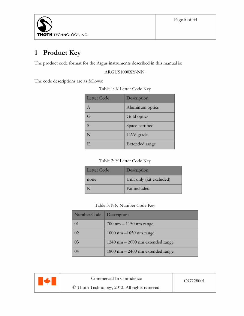
Release Notes
Issue Revisions Date
1.01 For release. April 2010
1.03 For release. October 2010
1.04 For release. Modified sections 10.4 (crossreference corrected), 10.6 (max fastener torquespecified), 11.1 (command messaging clarified),factory default commands corrected.
November 2010
1.05 Modified sections 10.3 and 10.4 to state correctspectra timing. Modified Table 4 to correct byte14 interpretation.
March 2011
1.06 Added GSE application screenshot. Addedinformation regarding CO2 retrieval andinstrument pointing configuration.
April 2011
1.07 Added product key to identify instrumentvariants.
August 2011
1.08 Modified section 8.8.1 to add informationregarding applications.
June 2012
1.09 Modified number codes October 2012
1.10 Corrected Table 4 for v19.0 bios Dec 2012
1.11 Updated letter codes March 2013
Page 5 of 34
Commercial In Confidence
© Thoth Technology, 2013. All rights reserved.
OG728001
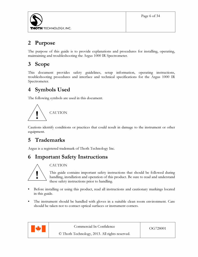
1 Product Key
The product code format for the Argus instruments described in this manual is:
ARGUS1000XY-NN.
The code descriptions are as follows:
Table 1: X Letter Code Key
Letter Code Description
A Aluminum optics
G Gold optics
S Space certified
N UAV grade
E Extended range
Table 2: Y Letter Code Key
Letter Code Description
none Unit only (kit excluded)
K Kit included
Table 3: NN Number Code Key
Number Code Description
01 700 nm – 1150 nm range
02 1000 nm –1650 nm range
03 1240 nm – 2000 nm extended range
04 1800 nm – 2400 nm extended range
Page 6 of 34
Commercial In Confidence
© Thoth Technology, 2013. All rights reserved.
OG728001
2 PurposeThe purpose of this guide is to provide explanations and procedures for installing, operating,maintaining and troubleshooting the Argus 1000 IR Spectrometer.
3 ScopeThis document provides safety guidelines, setup information, operating instructions,troubleshooting procedures and interface and technical specifications for the Argus 1000 IRSpectrometer.
4 Symbols Used
The following symbols are used in this document.
CAUTION
Cautions identify conditions or practices that could result in damage to the instrument or otherequipment.
5 Trademarks
Argus is a registered trademark of Thoth Technology Inc.
6 Important Safety Instructions
CAUTION
This guide contains important safety instructions that should be followed duringhandling, installation and operation of this product. Be sure to read and understandthese safety instructions prior to handling.
• Before installing or using this product, read all instructions and cautionary markings locatedin this guide.
• The instrument should be handled with gloves in a suitable clean room environment. Careshould be taken not to contact optical surfaces or instrument corners.
!
!
Page 7 of 34
Commercial In Confidence
© Thoth Technology, 2013. All rights reserved.
OG728001
• Do not attempt to open or unseal the unit. This product contains no serviceable parts.
• The instrument shall be accommodated in a temperature and humidity controlled clean roomof cleanliness class no worse than 100,000 during handling, assembly, integration and test.
• Anti-static grounding procedures must be observed when handling the instrument orinterface electronics. Care should be taken to align connector keys prior to insertion ofinstrument interface.
• Do not shock the instrument physically or expose this unit to liquids of any type.
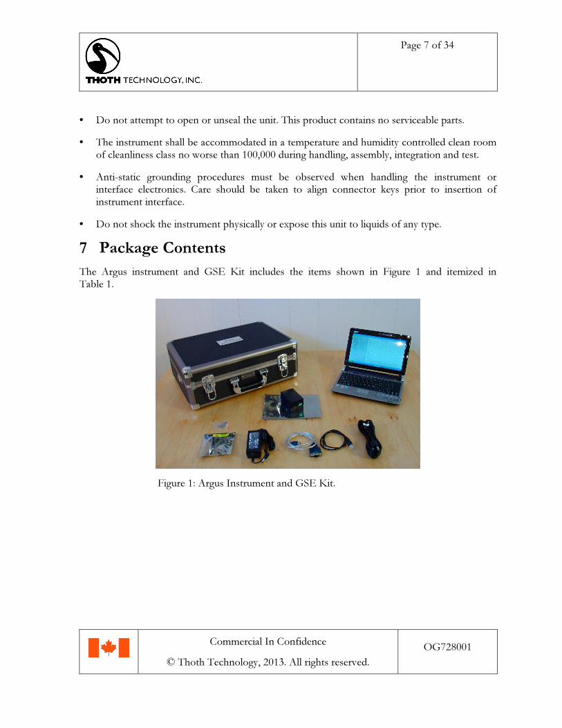
7 Package ContentsThe Argus instrument and GSE Kit includes the items shown in Figure 1 and itemized inTable 1.
Figure 1: Argus Instrument and GSE Kit.

Page 8 of 34
Commercial In Confidence
© Thoth Technology, 2013. All rights reserved.
OG728001
Table 1: Argus GSE Kit Contents
Item Location (Figure 1) Description
1 Center Argus unit
2 Top left Shipping case
3 Top right Argus ground test display laptop
4 Bottom Left Argus power and communications interfacecable, example electrical and mechanicalmounting hardware.
5 Bottom Center Laptop serial interface USB adapter
6 Bottom Center Right Argus power USB adapter (5V)
7 Bottom Center Left Laptop power module (19V)
8 Bottom Right Laptop mains power cable (NEMA 5-15 3-PinUSA Plug)
8 Product FeaturesThe spectrometer operates in the near infrared band in the standard range or in extended rangeversions. For instrument spectral variations please see the product key. Argus features a surfaceresolution of approximately 1.5 km when deployed in Low Earth Orbit (LEO). The device uses adetector array of 1x256 elements that is actively cooled. Each pixel has a native radiometricresolution of 10-bit that may be enhanced to 13-bit performance by utilizing the scan countsetting to co-add successive spectra. The device includes a microcontroller, which controls theinstrument’s components. The device operates typically in a continuous single-pixel scanningmode with approximately 100 illuminated spectral channels. The mass of the completespectrometer is less than 230 g.
8.1 SpecificationsThe technical specifications for Argus 1000 are summarised in Table 2, below.
Page 9 of 34
Commercial In Confidence
© Thoth Technology, 2013. All rights reserved.
OG728001
Table 2: Technical Specifications, Argus 1000 Spectrometer
Argus 1000 Specification1. Type Grating spectrometer
2. Configuration Single aperture spectrometer
3. Field of View 0.15º viewing angle around centered camera boresight with 15mmfore-optics
4. Mass >230 g
5. Accommodation 45 mm x 50 mm x 80 mm
6. Operating Temp. -20ºC to +40ºC operating temperature
7. Survival Temp. -25ºC to + 50ºC survival temperature
8. Detector 256 element InGaAs diode arrays with Peltier cooler (100 activechannels)
9. Grating 300 g/mm
10. Electronics microprocessor controlled 10-bit ADC with co-adding feature toenhance precision to 13-bit, 3.6-4.2V input rail 250mA-1500mA(375mA typical)
11. Operational Modes –Continuous cycle, constant integration time with co-adding feature
–Adaptive Exposure mode
12. Data Delivery Fixed length parity striped packets of single or co-added spectra withsequence number, temperature, array temperature and operatingparameters
13. Interface Prime and redundant serial interfaces RS232 protocol
14. Spectral Channels 100 (typical)
15. Integration Time 500 µs to 4.096 sec
16. Handling Shipped by courier in ruggedized carrying case
8.2 Detector System
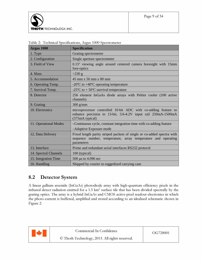
A linear gallium arsenide (InGaAs) photodiode array with high-quantum efficiency pixels in theinfrared detect radiation emitted for a 1.5 km2 surface tile that has been divided spectrally by thegrating optics. The array is a hybrid InGaAs and CMOS acitve-pixel readout electronics in whichthe photo-current is buffered, amplified and stored according to an idealised schematic shown inFigure 2.
Page 10 of 34
Commercial In Confidence
© Thoth Technology, 2013. All rights reserved.
OG728001
Figure 2: Principle of operation.
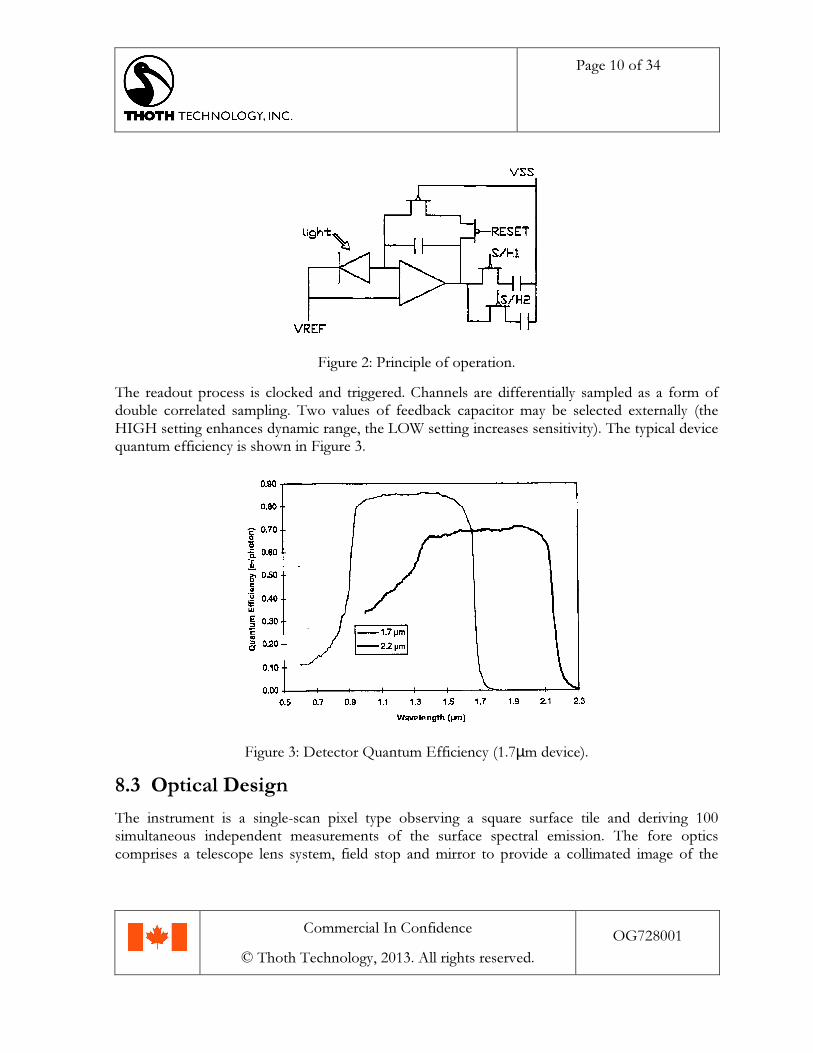
The readout process is clocked and triggered. Channels are differentially sampled as a form ofdouble correlated sampling. Two values of feedback capacitor may be selected externally (theHIGH setting enhances dynamic range, the LOW setting increases sensitivity). The typical devicequantum efficiency is shown in Figure 3.
Figure 3: Detector Quantum Efficiency (1.7µm device).
8.3 Optical DesignThe instrument is a single-scan pixel type observing a square surface tile and deriving 100simultaneous independent measurements of the surface spectral emission. The fore opticscomprises a telescope lens system, field stop and mirror to provide a collimated image of the
Page 11 of 34
Commercial In Confidence
© Thoth Technology, 2013. All rights reserved.
OG728001
surface tile onto the reflective grating. The reflective grating reflects a spectrally divided image (inthe vertical plane) onto another mirror that focuses the first spectral order of the surface tileimage onto the detector. The particular optical configuration is determined by Thoth’s customdesign tool. Spectrometers may be customized for particular spectral ranges or resolution bychoice of grating type and optical element placement.
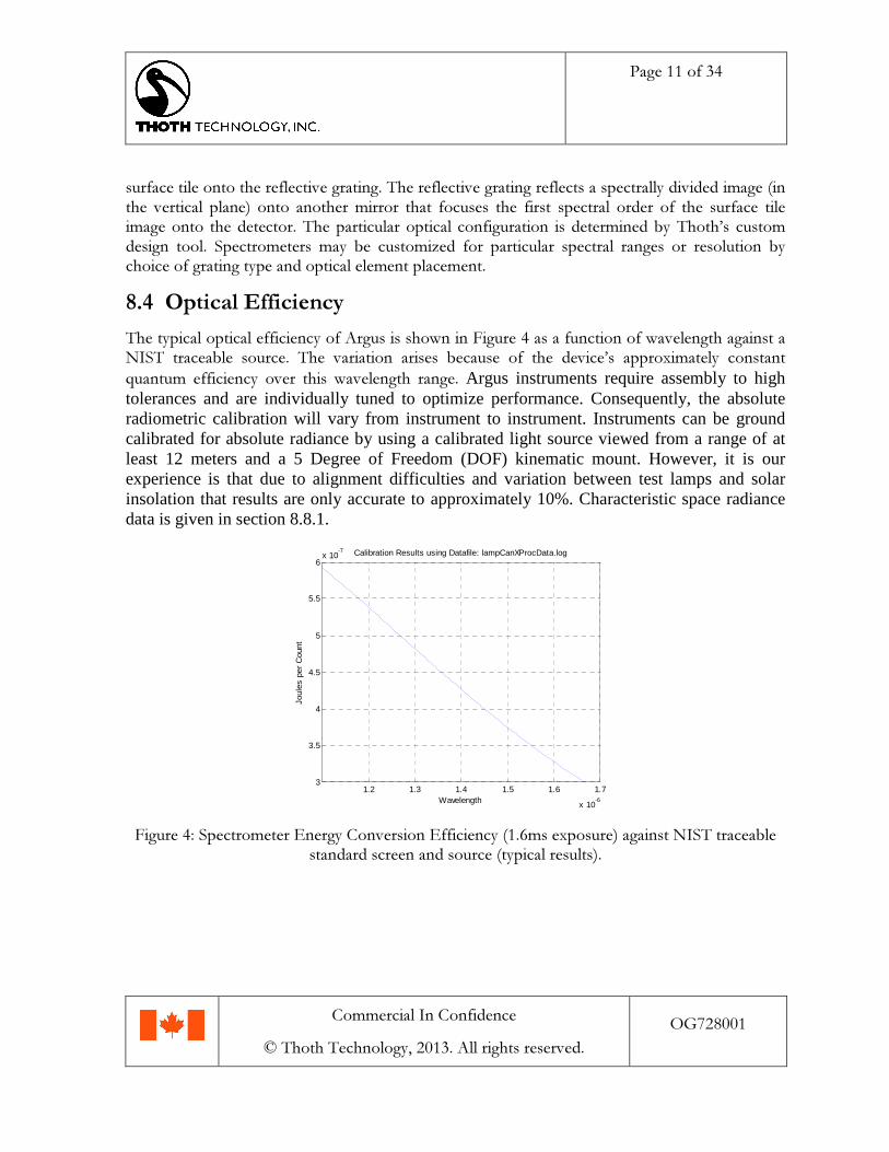
8.4 Optical EfficiencyThe typical optical efficiency of Argus is shown in Figure 4 as a function of wavelength against aNIST traceable source. The variation arises because of the device’s approximately constantquantum efficiency over this wavelength range. Argus instruments require assembly to hightolerances and are individually tuned to optimize performance. Consequently, the absoluteradiometric calibration will vary from instrument to instrument. Instruments can be groundcalibrated for absolute radiance by using a calibrated light source viewed from a range of atleast 12 meters and a 5 Degree of Freedom (DOF) kinematic mount. However, it is ourexperience is that due to alignment difficulties and variation between test lamps and solarinsolation that results are only accurate to approximately 10%. Characteristic space radiancedata is given in section 8.8.1.
1.2 1.3 1.4 1.5 1.6 1.7
x 10-6
3
3.5
4
4.5
5
5.5
6x 10
-7
Wavelength
Joul
es p
er C
ount
Calibration Results using Datafile: lampCanXProcData.log
Figure 4: Spectrometer Energy Conversion Efficiency (1.6ms exposure) against NIST traceablestandard screen and source (typical results).
Page 12 of 34
Commercial In Confidence
© Thoth Technology, 2013. All rights reserved.
OG728001
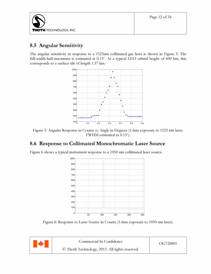
8.5 Angular SensitivityThe angular sensitivity in response to a 1523nm collimated gas laser is shown in Figure 5. Thefull-width-half-maximum is estimated at 0.15o. At a typical LEO orbital height of 600 km, thiscorresponds to a surface tile of length 1.57 km.
0 0.1 0.2 0.3 0.4 0.5 0.6100
200
300
400
500
600
700
800
900
1000
Figure 5: Angular Response in Counts vs. Angle in Degrees (1.6ms exposure to 1523 nm laser.FWHM estimated as 0.15o).
8.6 Response to Collimated Monochromatic Laser SourceFigure 6 shows a typical instrument response to a 1050 nm collimated laser source.
50 100 150 200 2500
100
200
300
400
500
600
700
800
900
1000
Figure 6: Response to Laser Source in Counts (1.6ms exposure to 1050 nm laser).
Page 13 of 34
Commercial In Confidence
© Thoth Technology, 2013. All rights reserved.
OG728001
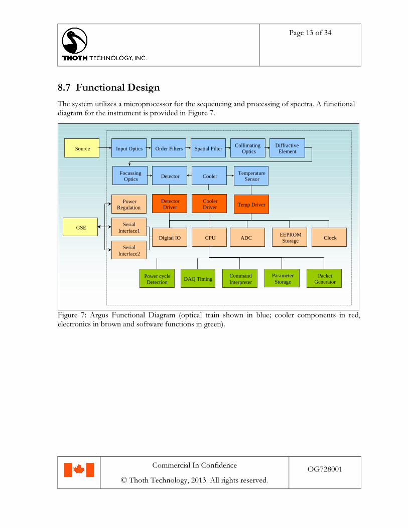
8.7 Functional DesignThe system utilizes a microprocessor for the sequencing and processing of spectra. A functionaldiagram for the instrument is provided in Figure 7.
Order Filters Spatial FilterDiffractive
ElementCollimating
OpticsInput Optics
FocussingOptics Detector
Source
DetectorDriver
CPU ADC Clock
SerialInterface2
SerialInterface1
PowerRegulation
Cooler
Digital IO
PacketGenerator
CommandInterpreter
DAQ Timing
TemperatureSensor
ParameterStorage
EEPROMStorage
Power cycleDetection
CoolerDriver
GSE
Temp Driver
Figure 7: Argus Functional Diagram (optical train shown in blue; cooler components in red,electronics in brown and software functions in green).

Page 14 of 34
Commercial In Confidence
© Thoth Technology, 2013. All rights reserved.
OG728001
8.8 Applications8.8.1 Observing atmospheric gas and mineral species
Figure 8: Industrial Greenhouse Gas Emitters.
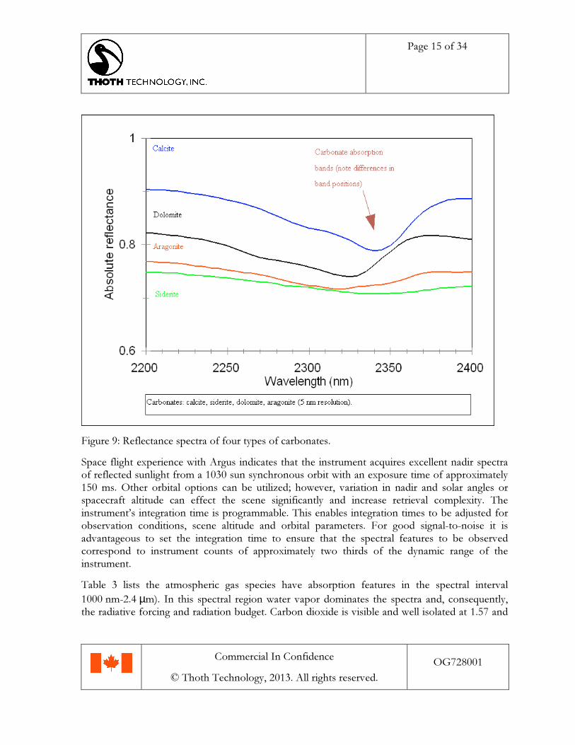
Argus can be utilized to map the spatial variation of greenhouse gases and to identify rocks andminerals with known reflectance spectra. Measurement interpretation requires spacecraft attitudeinformation for an accurate geolocation of the spectrometer surface pixel, application of aradiative transfer retrieval algorithm and knowledge of surface cloud conditions and topography.Utilizing a near nadir-pointing configuration, the spectrometer can record infrared radiationemitted from the Earth's surface and atmosphere to space. By application of optical absorptionspectroscopy, absorption and, consequently the column densities of particular atmospheric gasspecies may be obtained. The simplest methods such as differential optical absorptionspectroscopy (DOAS) are similar to computing the intensity ratio between closely spectrallyassociated absorption and non-absorption features. For mineralogical survey and by applicationof reflectance spectroscopy, different rock and mineral types may be identified where theatmosphere. Reflectance spectroscopy has found application in space exploration and is usedroutinely on Earth for detection and characterization of organic molecules in the laboratory. Forbiological exploration, organic molecules containing aliphatic O-H, C-H, and C-O groups exhibitabsorption bands in the 1700 and 2400 nm regions. Detection limits for these types of organiccompounds in laboratory equipment are on the order of a few tenths of one percent. Figure 9shows reflectance spectra for typical rock types. Iron content may be inferred from the strongabsorption feature in the lower wavelength region. The absorption of infrared radiation bycarbonates has a distinct signature that varies with rock type, enabling classification. Theextended range Argus 1000EK-04 is recommended for reflectance spectroscopy applications inthe 1800 nm - 2400 nm band.
Page 15 of 34
Commercial In Confidence
© Thoth Technology, 2013. All rights reserved.
OG728001
Figure 9: Reflectance spectra of four types of carbonates.
Space flight experience with Argus indicates that the instrument acquires excellent nadir spectraof reflected sunlight from a 1030 sun synchronous orbit with an exposure time of approximately150 ms. Other orbital options can be utilized; however, variation in nadir and solar angles orspacecraft altitude can effect the scene significantly and increase retrieval complexity. Theinstrument’s integration time is programmable. This enables integration times to be adjusted forobservation conditions, scene altitude and orbital parameters. For good signal-to-noise it isadvantageous to set the integration time to ensure that the spectral features to be observedcorrespond to instrument counts of approximately two thirds of the dynamic range of theinstrument.
Table 3 lists the atmospheric gas species have absorption features in the spectral interval
1000 nm-2.4 µm). In this spectral region water vapor dominates the spectra and, consequently,the radiative forcing and radiation budget. Carbon dioxide is visible and well isolated at 1.57 and

Page 16 of 34
Commercial In Confidence
© Thoth Technology, 2013. All rights reserved.
OG728001
1.61 µm and is clearly observable in space data. At these wavelengths absorption by carbondioxide is approximately one hundred times greater than that of water vapour and a number ofspectral pixels are well correlated with CO2 absorption. Data from the first spaceflight of Argusindicate that CO2 absorption that is stronger significantly than predicted by a linear radiative pathand assuming a single-surface reflection. CO2 absorption is also enhanced by the presence ofclouds and aerosols. Retrievals to invert column absorption of CO2 to CO2 atmosphericconcentration must account for topographical effects in addition to enhanced absorption forcingby clouds and aerosols.
Oxygen can also be observed; however, a shorter integration time is required than for carbon-dioxide observation. Carbon Monoxide (CO) and Hydrogen Fluoride (HF) is not detected inspectra because of feature contamination by other absorbing gases (water vapor). There is some
evidence of methane (CH4) absorption at 1.63 µm; however it is contaminated with carbon-
dioxide features. The extended range detector is recommended for the observation of methane
(CH4) features at 2.25 µm. The integrated intensity is highly correlated with surface albedo.
Spectra contaminated by cloud cover show typically reduced gas absorption, a blackbody-likeresponse and increased intensity. Results of spectra acquired over Canada in 2008 are shown inFigure 9. We estimate that the peak radiance observed in this scene is equivalent to 0.04 Wm2
sr-1 nm-1.

Page 17 of 34
Commercial In Confidence
© Thoth Technology, 2013. All rights reserved.
OG728001
Table 3: Absorbing Species
Gas Absorption Strength
Oxygen (O2) 1.25µm (10-24 mol.cm-2)
Carbon Dioxide (CO2) 1.57µm (10-23 mol.cm-2)
1.61µm (10-22 mol.cm-2)
2.05µm (10-21 mol.cm-2)
Water (H2O) 900nm (10-21 mol.cm-2)
1.2µm (10-21 mol.cm-2)
1.4µm (10-19 mol.cm-2)
Carbon Monoxide (CO) 1.63µm (10-22 mol.cm-2)
Methane (CH4) 1.67µm (10-20 mol.cm-2)
2.25µm (10-20 mol.cm-2)
Hydrogen Fluoride (HF) 1.265µm (10-19 mol.cm-2)

Page 18 of 34
Commercial In Confidence
© Thoth Technology, 2013. All rights reserved.
OG728001
Figure 10: Data Acquired (successive spectra, smoothed features) from Argus 1000 on CanX-2platform over Ontario, Canada, December 2008.

Page 19 of 34
Commercial In Confidence
© Thoth Technology, 2013. All rights reserved.
OG728001
9 Ground System Electronics Setup
Referring to Figure 1 for item identification:
1. Setup the Argus Laptop Display Terminal and power it up.
2. Connect the blue Serial to USB converter to left (single) USB port on the laptop. Note if leftport is used, serial port will mount as COM3 rather than COM4 or COM5 that requiremanual selection when launching ‘Argus GSE’.
3. Connect the USB to power adapter (black cable) jack plug to the Power and CommunicationsInterface Cable.
4. Place or mount the instrument unit in a safe condition.
5. Aligning the connector key on the Power and Communications Interface Cable connectormate the DF-11 plug with the instrument.
6. Connect the USB DB-9 serial port (blue connector) to the corresponding port on the Powerand Communications Interface Cable.
7. From the start menu, select and run the ‘Argus GSE’ application.
8. Power the instrument by USB to power cable to one of the laptop USB ports.
9. After correct setup Argus GSE application will report instrument spectra and “Argus Status:In Sync” (bottom left of window).
The interface and cable setups are configured for a particular Argus GSE and instrument andare not designed to be interchangeable with other Argus instruments. For reliable operationand as a condition of warranty it is not recommended that the Argus GSE laptop terminal beconnected to the internet either wirelessly or by LAN connection or that other applications beinstalled or operated on the Argus GSE laptop. Thoth recommends that the display terminal bededicated solely to instrument operation.
10 Argus GSE Test ApplicationSoftware for the operation of Argus is provided on the ground station laptop. Launch the “ArgusGSE” application from the start menu or by shortcut to access a data display terminal developedfor testing purposes. This terminal is not intended for data analysis but provides a means tocommand the instrument and check basic functionality.

Page 20 of 34
Commercial In Confidence
© Thoth Technology, 2013. All rights reserved.
OG728001
The application comprises two windows. The left pane shows the instrument status. The rightpane shows the spectra as a function of counts against frequency number. A screenshot of theGSE application is shown below.
Fig 11: Argus GSE Screenshot (response to 1150 nm laser at range of 12m).
10.1 Argus Status MessageThe Argus Status message is displayed in the bottom left of the application window. “ArgusStatus: Lost Sync” occurs if Argus GSE has lost contact with Argus or is waiting for a frame withan integration time exceeding 0.5 seconds. “Argus Status: In Sync” is indicated when the ArgusGSE application is in communication with the instrument.
10.2 Adjusting Spectrum Pixel RangeThe spectral pixel range may be adjusted by right-clicking with the cursor on the spectral displaypane. The upper pixel and lower pixel display range may be set using the increment buttons or byinserting a value between 0 and 255.
10.3 Commanding the Instrument SettingsThe instrument may be commanded by selecting the settings tab. Note that the pane containingthe Argus ID must be active (selected by the cursor) in order to command the instrument.

Page 21 of 34
Commercial In Confidence
© Thoth Technology, 2013. All rights reserved.
OG728001
Exposure time, Number of Scans, Capacitor, Temperature, Adaptive exposure and Load/SaveDefult settings may be programmed from the window menus.
10.4 Data LoggingThe Argus GSE application may be used to log instrument data using the “Data Logging” tab.The data logging interval to create a new file with automatic time-stamped file name can be set as1 min, 10 min or 60 min. Raw data is recorded, preceded by a windows standardized time stampencoding the packet write time. Alternate serial port logging programs may be utilized if raw-onlydata is required.
10.5 CommunicationsThe Argus GSE applications defaults to standard instrument communications settings on startupand utilizes a serial to USB converter port on COM3. Other settings may be specified using the“communications” tab.
11 Integration
11.1 Power Interface11.1.1.1 Argus requires a continuous input feed of 572 mA (375 mA typical) at 3.2V DC
to 4.6V DC (nominally), while the instrument remains powered.
11.1.1.2 Argus provides current regulation over the specified input voltage ranges andtypically draws 375 mA at standard temperature and pressure (STP) conditions. Ifthe temperature and/or voltage are varied over the design range then Argus maydraw up to 575 mA. Additionally, the instrument functions over a wider range ofDC voltages however, this is not recommended. The power supplied to Argusshould never exceed 5.0V DC.
11.1.1.3 The power supplied to Argus may be switched on and off depending on whetherArgus operation is required. Argus will power down automatically atapproximately 3.0V DC however this is not recommended.
11.1.1.4 The in-rush current (that occurs when the instrument is powered) may reach1500 mA. In-rush current transients settle within 10 ms of Argus activation.
11.1.1.5 The Argus instrument casing shall be maintained at ground potential.

Page 22 of 34
Commercial In Confidence
© Thoth Technology, 2013. All rights reserved.
OG728001
11.2 Communications Interface11.2.1.1 The instrument features two asynchronous RS-232 serial ports.
11.2.1.2 Both serial ports are connected and configured at 115,200 baud, 8 bits, one stopbit, no parity (data format 8N1).
11.2.1.3 Both serial ports deliver the instrument’s data packet stream and may receivecorrectly formatted instrument commands on either port. Only one port shouldbe used for commanding. Simultaneous commanding of ports is notrecommended.
11.2.1.4 The maximum data rate between the instrument and either OBC is 230kbps.
11.2.1.5 The payload electronics is designed to tolerate a constant logic high on its inputs,even when the unit is powered off.
11.3 Timing of Spectra Acquisition and Co-Adding Feature11.3.1.1 The instrument shall acquire spectra for duration determined by the
Integration_Time_Setting and then packetize and transmit this data in asubsequent 55 mS time slice. Where the Number_of_Scans_Setting setting is setto between n = 2 and 9, the instrument shall acquire n successive spectra co-adding them to a maximum precision of 16-bit before transmitting them in thelast 55 mS timeslice according to the following example timing diagram:
Time
Int1 sample1 Int2 transmit
32mS 55mS 32mS 55mS
Frame1
sample2
55mS
pack
32mS
Figure 11: Spectra Acquisition Timing Example for 32mS integration time and number of scansset to 2 resulting in a (32+55)*3=261mS total integration time at a resolution of 11-bit.
Page 23 of 34
Commercial In Confidence
© Thoth Technology, 2013. All rights reserved.
OG728001
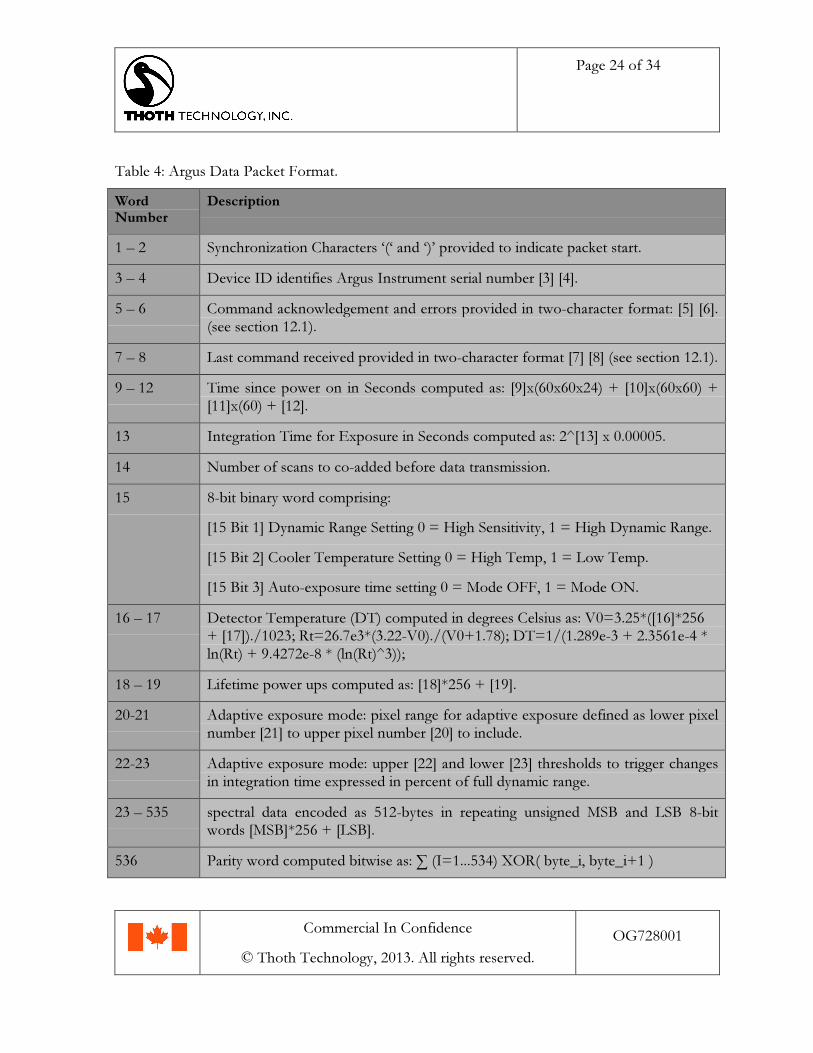
11.4 Data Packet Format11.4.1.1 The spectrometer provides data over the serial communications interface to an
Onboard Computer or listening device in fixed length unsigned 8-bit words. Datapackets are transmitted continuously at a cycle period determined as(55mS+Integration_Time_Setting) * (Number_of_Scans_Setting + 1). Thepacket format is shown in Table 4.
Page 24 of 34
Commercial In Confidence
© Thoth Technology, 2013. All rights reserved.
OG728001
Table 4: Argus Data Packet Format.
Word
Number
Description
1 – 2 Synchronization Characters ‘(‘ and ‘)’ provided to indicate packet start.
3 – 4 Device ID identifies Argus Instrument serial number [3] [4].
5 – 6 Command acknowledgement and errors provided in two-character format: [5] [6].(see section 12.1).
7 – 8 Last command received provided in two-character format [7] [8] (see section 12.1).
9 – 12 Time since power on in Seconds computed as: [9]x(60x60x24) + [10]x(60x60) +[11]x(60) + [12].
13 Integration Time for Exposure in Seconds computed as: 2^[13] x 0.00005.
14 Number of scans to co-added before data transmission.
15 8-bit binary word comprising:
[15 Bit 1] Dynamic Range Setting 0 = High Sensitivity, 1 = High Dynamic Range.
[15 Bit 2] Cooler Temperature Setting 0 = High Temp, 1 = Low Temp.
[15 Bit 3] Auto-exposure time setting 0 = Mode OFF, 1 = Mode ON.
16 – 17 Detector Temperature (DT) computed in degrees Celsius as: V0=3.25*([16]*256+ [17])./1023; Rt=26.7e3*(3.22-V0)./(V0+1.78); DT=1/(1.289e-3 + 2.3561e-4 *ln(Rt) + 9.4272e-8 * (ln(Rt)^3));
18 – 19 Lifetime power ups computed as: [18]*256 + [19].
20-21 Adaptive exposure mode: pixel range for adaptive exposure defined as lower pixelnumber [21] to upper pixel number [20] to include.
22-23 Adaptive exposure mode: upper [22] and lower [23] thresholds to trigger changesin integration time expressed in percent of full dynamic range.
23 – 535 spectral data encoded as 512-bytes in repeating unsigned MSB and LSB 8-bitwords [MSB]*256 + [LSB].
536 Parity word computed bitwise as: ∑ (I=1...534) XOR( byte_i, byte_i+1 )
Page 25 of 34
Commercial In Confidence
© Thoth Technology, 2013. All rights reserved.
OG728001
11.4.1.2 The electronics reads the detector thermistor resistance and record this data withevery spectra. The thermistor reading will be conditioned to a temperature in oCaccording to the algorithm given in Table 4.
11.5 Connectors11.5.1.1 The spacecraft shall provide all necessary external harnessing.
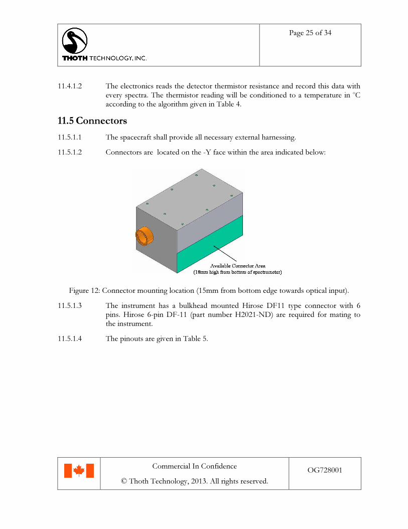
11.5.1.2 Connectors are located on the -Y face within the area indicated below:
Figure 12: Connector mounting location (15mm from bottom edge towards optical input).
11.5.1.3 The instrument has a bulkhead mounted Hirose DF11 type connector with 6pins. Hirose 6-pin DF-11 (part number H2021-ND) are required for mating tothe instrument.
11.5.1.4 The pinouts are given in Table 5.
Page 26 of 34
Commercial In Confidence
© Thoth Technology, 2013. All rights reserved.
OG728001
Table 5: Power Connector Pinouts
Signal Description Pin No. Description
COMMAND_RECEIVE1 1 Serial Data ReceivingPort A
V_POS 2 Positive Power (may beswitched)
COMMAND_RECEIVE2 3 Serial Data ReceivingPort B
DATA_TX1 4 Serial Data TransmissionPort A
GND 5 Ground
DATA_TX2 6 Serial Data TransmissionPort B
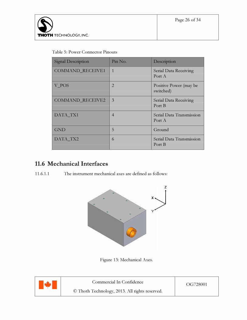
11.6 Mechanical Interfaces11.6.1.1 The instrument mechanical axes are defined as follows:
Figure 13: Mechanical Axes.
Page 27 of 34
Commercial In Confidence
© Thoth Technology, 2013. All rights reserved.
OG728001
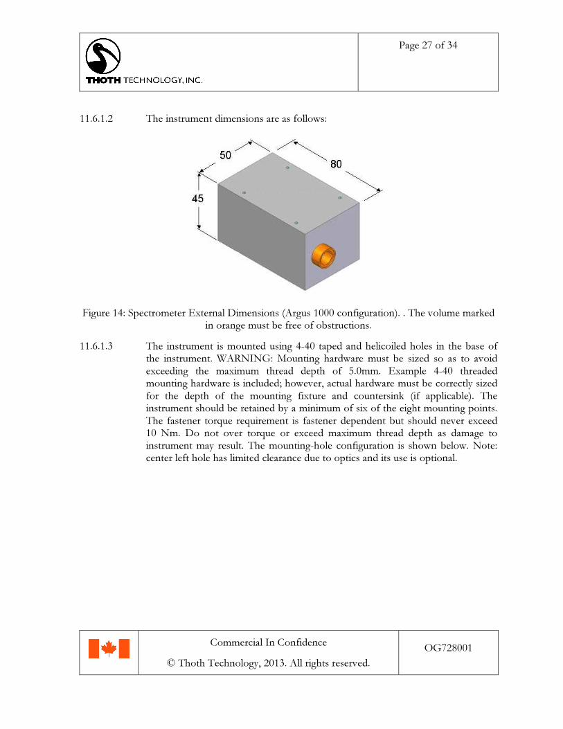
11.6.1.2 The instrument dimensions are as follows:
Figure 14: Spectrometer External Dimensions (Argus 1000 configuration). . The volume markedin orange must be free of obstructions.
11.6.1.3 The instrument is mounted using 4-40 taped and helicoiled holes in the base ofthe instrument. WARNING: Mounting hardware must be sized so as to avoidexceeding the maximum thread depth of 5.0mm. Example 4-40 threadedmounting hardware is included; however, actual hardware must be correctly sizedfor the depth of the mounting fixture and countersink (if applicable). Theinstrument should be retained by a minimum of six of the eight mounting points.The fastener torque requirement is fastener dependent but should never exceed10 Nm. Do not over torque or exceed maximum thread depth as damage toinstrument may result. The mounting-hole configuration is shown below. Note:center left hole has limited clearance due to optics and its use is optional.

Page 28 of 34
Commercial In Confidence
© Thoth Technology, 2013. All rights reserved.
OG728001
Figure 15: Spectrometer Mounting-hole Locations (ANSI/ASME 4-40 threads). Mountinghardware should not extend more than 5.0mm into threads. Do not over torque.
11.6.1.4 The entrance aperture is on the -X face. Its center is located 10mm from the edgeof the +Y side and 22.5 mm from the +Z side. The spectrometer entranceaperture is 15mm diameter. The instrument has no outer protrusions (except thepower connector) and should be mounted under the spacecraft skin, co-alignedwith a 16mm circular aperture to allow light entry. Optimally, the 16mm circularaperture port should be between 10mm and 50mm from the front face of theinstrument and should have blackened edges. Spectrometer faces other than themounting face should have no physical contact with other spacecraftcomponents. A minimium 2 mm gap on all external spectrometer faces isrecommended.
11.6.1.5 The connector is on -Y, with its center 13mm from the +X face and 5mm fromthe -Z face.
11.6.1.6 The approximate instrument mass is 215 g.
11.7 Environment11.7.1.1 The instrument core temperature should be maintained within tolerances for
operation and survival specified in Table 2.
Page 29 of 34
Commercial In Confidence
© Thoth Technology, 2013. All rights reserved.
OG728001
11.7.1.2 Argus type-S instruments are capable of surviving a vibration load of at least 12grms random and sinusoidal on all axes.
11.7.1.3 Argus type-S instruments contain no more than 0.1% collected volatilecondensable material.
11.7.1.4 Argus type-S instruments should be accommodated in a clean room of cleanlinessclass no worse than 100,000 during assembly integration and test; class 10,000recommended.
12 Operation
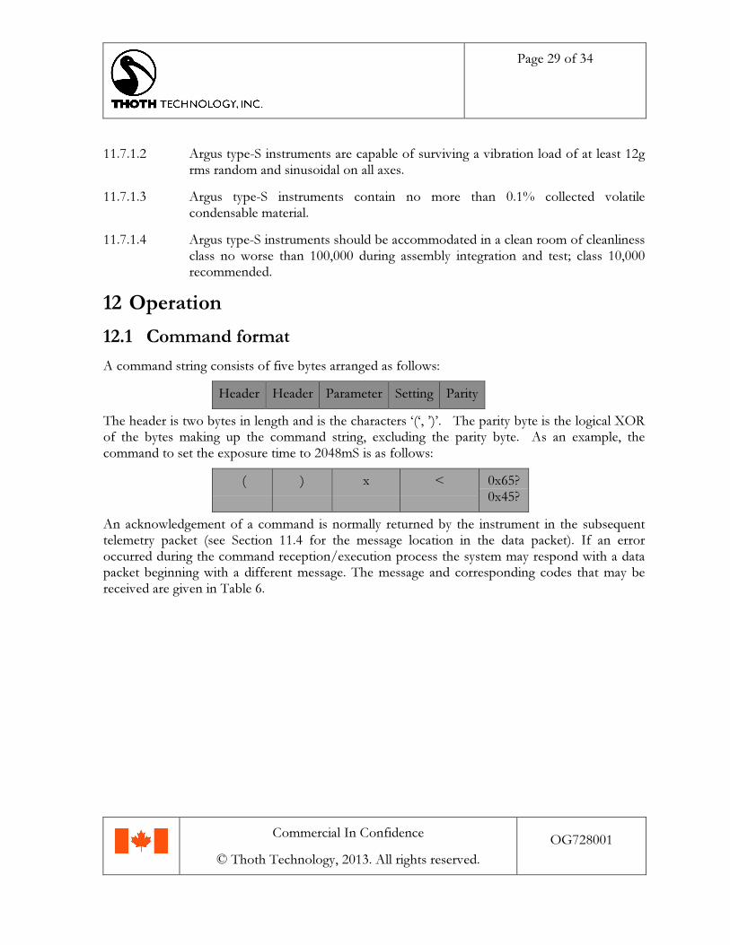
12.1 Command formatA command string consists of five bytes arranged as follows:
Header Header Parameter Setting Parity
The header is two bytes in length and is the characters ‘(‘, ’)’. The parity byte is the logical XORof the bytes making up the command string, excluding the parity byte. As an example, thecommand to set the exposure time to 2048mS is as follows:
( ) x < 0x65?0x45?
An acknowledgement of a command is normally returned by the instrument in the subsequenttelemetry packet (see Section 11.4 for the message location in the data packet). If an erroroccurred during the command reception/execution process the system may respond with a datapacket beginning with a different message. The message and corresponding codes that may bereceived are given in Table 6.

Page 30 of 34
Commercial In Confidence
© Thoth Technology, 2013. All rights reserved.
OG728001
Table 6: System Messages (see Section 11.4 for message location in data packet).
Message Description Packet Start Characters
NO STATUS MESSAGE TO COMMUNICATE "00"
PARAMETERS LOADED SUCCESSFULLY "PL"
POWER UP INITIATED "PU"
COMMAND ACKNOWLEDGED "AK"
RESET TO DEFAULT PROGRAM "DP"
ERROR RX TIMEOUT "EC"
ERROR EXPOSURE OUT OF RANGE "XR"
ERROR BAD PARITY "BP"
ERROR INVALID PARAMETER "IP"
ERROR SCAN COUNT OUT OF RANGE "SR"
ERROR CAP SELECT OUT OF RANGE "CR"
ERROR COOLER SELECT OUT OF RANGE "TR"

Page 31 of 34
Commercial In Confidence
© Thoth Technology, 2013. All rights reserved.
OG728001
12.1.1 Command List
12.1.1.1 Exposure Time
Parameter: ‘x’
Setting: ‘0’ 500uS‘1’ 1.0mS‘2’ 2.0mS‘3’ 4.0mS‘4’ 8.0mS‘5’ 16.0mS‘6’ 32mS‘7’ 64mS‘8’ 128mS‘9’ 256mS‘:’ 512mS‘;’ 1024mS ‘<’ 2048mS‘=’ 4096mS
12.1.1.2 Select Capacitor Setting
Parameter: ‘c’
Setting: ‘0’ High Sensitivity
‘1’ High Dynamic Range
12.1.1.3 Select Cooler Temperature Setting
Parameter: ‘t’
Setting: ‘0’ High temperature setting, (reduced current draw by 70 mA)
‘1’ Low temperature setting, (100mA cooler current draw)
12.1.1.4 Set Number of Scans to Count
Parameter: ‘s’
Setting: ‘1-9’ Number of spectra to co-add before data transmission.
Page 32 of 34
Commercial In Confidence
© Thoth Technology, 2013. All rights reserved.
OG728001
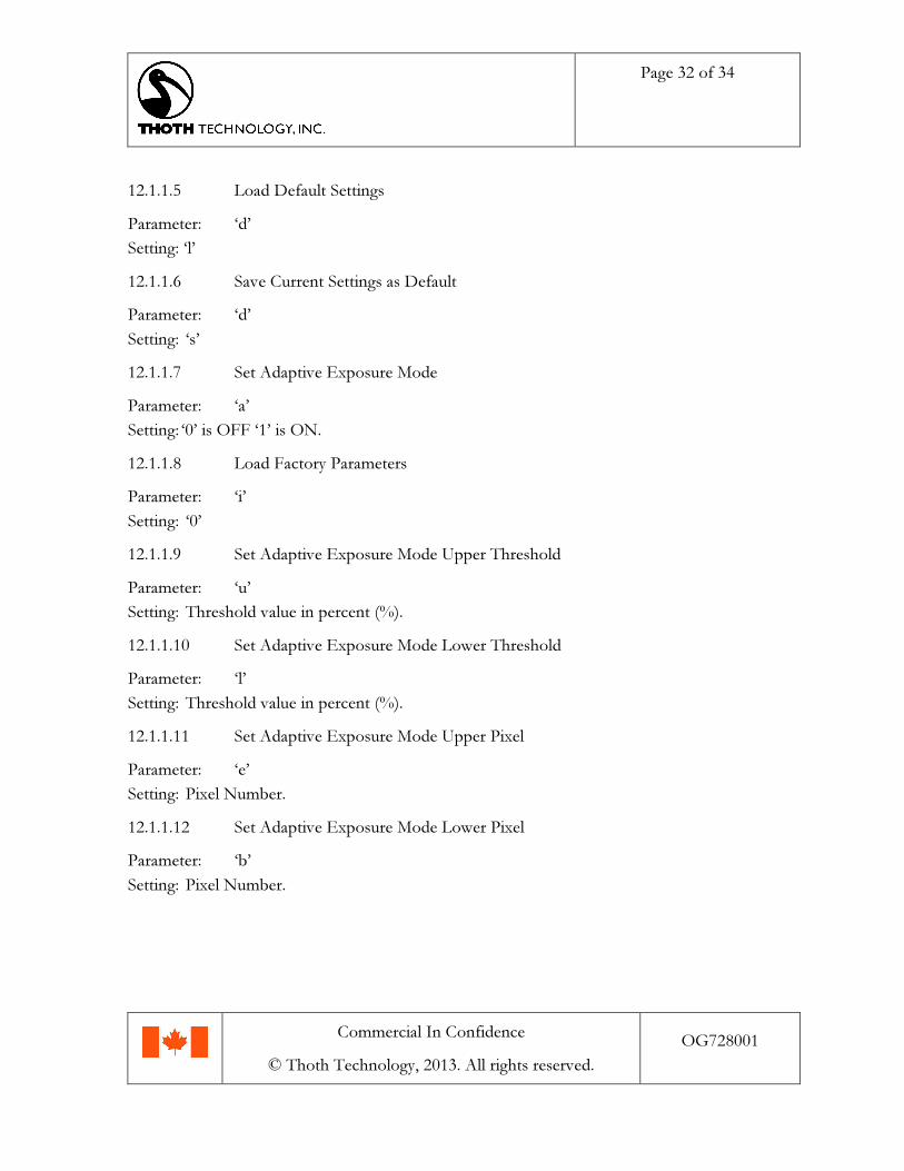
12.1.1.5 Load Default Settings
Parameter: ‘d’
Setting: ‘l’
12.1.1.6 Save Current Settings as Default
Parameter: ‘d’
Setting: ‘s’
12.1.1.7 Set Adaptive Exposure Mode
Parameter: ‘a’
Setting: ‘0’ is OFF ‘1’ is ON.
12.1.1.8 Load Factory Parameters
Parameter: ‘i’
Setting: ‘0’
12.1.1.9 Set Adaptive Exposure Mode Upper Threshold
Parameter: ‘u’
Setting: Threshold value in percent (%).
12.1.1.10 Set Adaptive Exposure Mode Lower Threshold
Parameter: ‘l’
Setting: Threshold value in percent (%).
12.1.1.11 Set Adaptive Exposure Mode Upper Pixel
Parameter: ‘e’
Setting: Pixel Number.
12.1.1.12 Set Adaptive Exposure Mode Lower Pixel
Parameter: ‘b’
Setting: Pixel Number.
Page 33 of 34
Commercial In Confidence
© Thoth Technology, 2013. All rights reserved.
OG728001
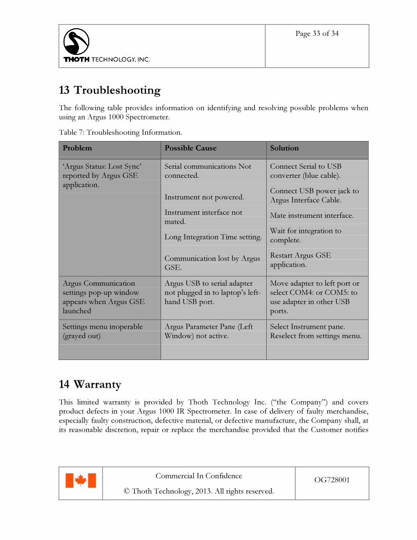
13 TroubleshootingThe following table provides information on identifying and resolving possible problems whenusing an Argus 1000 Spectrometer.
Table 7: Troubleshooting Information.
Problem Possible Cause Solution
‘Argus Status: Lost Sync’reported by Argus GSEapplication.
Serial communications Notconnected.
Instrument not powered.
Instrument interface notmated.
Long Integration Time setting.
Communication lost by ArgusGSE.
Connect Serial to USBconverter (blue cable).
Connect USB power jack toArgus Interface Cable.
Mate instrument interface.
Wait for integration tocomplete.
Restart Argus GSEapplication.
Argus Communicationsettings pop-up windowappears when Argus GSElaunched
Argus USB to serial adapternot plugged in to laptop’s left-hand USB port.
Move adapter to left port orselect COM4: or COM5: touse adapter in other USBports.
Settings menu inoperable(grayed out)
Argus Parameter Pane (LeftWindow) not active.
Select Instrument pane.Reselect from settings menu.
14 Warranty
This limited warranty is provided by Thoth Technology Inc. (“the Company”) and coversproduct defects in your Argus 1000 IR Spectrometer. In case of delivery of faulty merchandise,especially faulty construction, defective material, or defective manufacture, the Company shall, atits reasonable discretion, repair or replace the merchandise provided that the Customer notifies

Page 34 of 34
Commercial In Confidence
© Thoth Technology, 2013. All rights reserved.
OG728001
the Company of faults in writing within thirty (30) days of delivery; in such cases, the faultymerchandise becomes the property of the Company and must be returned to the Company.
There shall be no warranty for damages arising from normal wear, improper use, improperhandling, faulty installation or startup by the Customer or by a third party or for deficientbuilding provisions, including but not limited to unsuitable electrical provisions, exposure to fire,exposure to water or other liquids, or other unsuitable site properties. If, on inspection by theCompany of returned merchandise within the warranty period, it becomes apparent that a fault isdue to improper handling or use by the Customer, the Company may offer to fix themerchandise, and the costs of repair shall be borne by the Customer.
Any repair or modification to the merchandise performed by the Customer or by a third partywithout the prior written permission of the Company invalidates any warranty for faultymerchandise.
14.1 DisclaimerTHIS LIMITED WARRANTY IS THE SOLE AND EXCLUSIVE WARRANTYPROVIDED BY THOTH TECHNOLOGY INC. IN CONNECTION WITH THE ARGUS1000 IR SPECTROMETER AND IS, WHERE PERMITTED BY LAW, IN LIEU OF ALLOTHER WARRANTIES, CONDITIONS, GUARANTEES, REPRESENTATIONS,OBLIGATIONS AND LIABILITIES, EXPRESS OR IMPLIED, STATUTORY OROTHERWISE IN CONNECTION WITH THE PRODUCT, HOWEVER ARISING(WHETHER BY CONTRACT, TORT, NEGLIGENCE, MANUFACTURER’S LIABILITYOR OTHERWISE) INCLUDING WITHOUT RESTRICTION ANY IMPLIEDWARRANTY OR CONDITION OF QUALITY, MERCHANTABILITY OR FITNESS FORA PARTICULAR PURPOSE.
The Company makes no warranty that the items described herein are suitable or fit for aparticular purpose. The Company makes no representation as to condition or character of themerchandise and in no event will be liable for any special, direct, indirect, incidental orconsequential damages, losses, costs or expenses however arising whether in contract or tortincluding without restriction any economic losses of any kind, any loss or damage to property,any personal injury, any damage or injury arising from or as a result of misuse or abuse, or theincorrect installation, integration or operation of this product. The company may vary productspecifications, production methods, software and components without prior warning.