argos – orpheus-x2 user interface - wseas · argos – orpheus-x2 user interface l.zalud, t....
TRANSCRIPT

ARGOS – ORPHEUS-X2 User Interface
L.ZALUD, T. NEUZIL, L. KOPECNY Department of Control and Instrumentation
Brno University of Technology Kolejni 4, Brno, 612 00
CZECH REPUBLIC http://www.orpheus-project.cz
Abstract: - Orpheus reconnaissance robotic system Orpheus-X2 developed at Department of Control and Instrumentation is described. The paper is focused to ARGOS visualization software system for sensory supported visual telepresence control of mobile robots. The article describes augmented reality part of the system - namely visual telepresence, 2D and 3D proximity scanner data and inertial sensor data presentation. The concept of real video in background of operator’s view with a series of Virtual Head-up Displays is presented. Advantages of ARGOS for real-time data fusion of CCD color camera, thremovision and 3D proximity scanner are depicted. Key-Words: - Mobile Robot, Augmented Reality, Inertial Sensor, Proximity Scanner, CCD camera 1 Introduction The Orpheus robotic system has been developed in our department from the beginning of year 2003. The project is a natural continuation of “mainly research” U.T.A.R. project [1], [2], [3]. The robot is intended as a teleoperated system for various reconnaissance missions – it may serve as a rescue robot, pyrotechnical robot or a robot for firemen. So its primary mission is to search objects (mostly live humans) in harsh terrain such as building ruins. The Orpheus robotic system consists of two main parts:
• Orpheus mobile robot (see Fig. (1)), • operator’s station.
Since the robot is supposed to be operated by people that are not robotists, creation of user-friendly human-robot interface and appropriate data representation are very important parts of the project.
Fig. 1. Orpheus robot.
The paper describes the operator’s station and user interface as well. Great emphasis is placed on operator’s situation awareness during the mission. It is substantially improved by integration of inertial sensors to the head movement sensing unit and inclination measurement unit of the Orpheus robotic system together with its proper representation to the operator. 2 User Interface The Orpheus-X2 user interface represents next step in the constant improvements of user interfaces during U.T.A.R. and Orpheus robotic systems development [10], [11]. The improvements are both in hardware and software part, but the software is much more crucial. The robot is controlled by operator with help of so called visual telepresence. The operator has a head mounted display with inertial head movement sensor. The sensing unit is Intersense InterTrax2. The movements of the operator are measured, transformed and transmitted to Orpheus. The camera copies movements of the operator’s head and since the operator can see the picture from it, he/she feels to be in the robot’s environment. The movements of the whole robot and all of the other functions are controlled by advanced two-hand joystick system similarly to airplanes. The used concept is known as Hands on Throttle and Stick (H.O.T.A.S.) and the basic idea is that the operator does not need to use any other control devices during the whole mission. 3 Hardware The main motto of the Orpheus-X2 user interface is flexibility depending on mission needs. Since all of the data are transferred using Ethernet connection, the
Proceedings of the 5th WSEAS Int. Conf. on Signal Processing, Robotics and Automation, Madrid, Spain, February 15-17, 2006 (pp92-97)
operator’s station may be very simplistic. The most simplistic, but fully functional version (excluding somewhat limited ARGOS-PDA) is a notebook with wireless joypad, but the operator's station may vary up to a system containing powerful PC with external Wi-fi access point, two-hands-joystick, VR goggles with head movements sensor and a digital data-projector. 3 Software - ARGOS-PDA The very novel part of the Orpheus robotic system is the PDA version of the operator's station. Although only the basic functions of the Orpheus system may be nowadays controlled by it and the device itself may be only seen as a demonstration of the capabilities, it represents an important tool to make the Orpheus system much more versatile. The hardware used is Pocket Look 720 PDA by Siemens company and the main features of it are:
• Processor ARM 620MHz, • display resolution up to 640x480, • Wi-fi capabilities.
Since the PDA is equipped with Microsoft Windows Mobile 2003, a new version of the ARGOS system called ARGOS-PDA had to be developped. The system provides almost complete Win32 core but does not support DirectX, and has only very limited capabilities for displaying data quickly. Since the primary idea was to display also video data a fast data displaying method based on direct video memory transfers had to be developed by the author. The PDA user interface is rather simplistic. The middle part includes a video display from actual camera, the upper part displays the basic info about the robot.The operator may control movements of the robot, and switch among the cameras. 5 Software - ARGOS system The software part of the improvements strongly depends on ARGOS (Advanced Robotics Graphical Operation System) development and the fact the system now widely uses DirectX components. The scheme of ARGOS system is depicted on Fig.(2). The following components of DirectX 9.0c are used: Direct3D - to draw 3D any objects and to display 2D objects. Since DirectX has not 2D drawing library, the author’s have developed 2D object drawing library from the point level, based on fast drawing to memory. The library is used to draw the objects to Direct3D off-screen surfaces that may be than rendered to the 3D scene in the form of a surface or texture.
Fig. 2. ARGOS scheme.
The library works in RGBA color mode, with alpha parameter defining the transparency of each pixel. This solution is very versatile, since every pixel has its own transparency, but also the textures and surfaces may be alpha-blended. The library uses optimized Bresenham's algorithms for line and ellipse drawing, horizontal and vertical lines are also optimized making filled rectangular areas drawing very fast. The library does not use any clipping to achieve fast drawing, and the border-guarding is on application programmer responsibility. DirectShow - to perform video-grabbing. The advantage of DirectShow is that virtually any Microsoft Windows compatible video-digitizing device may be used with it. On the Orpheus robot side (ARGOS server), the grabbed images are compressed by JPEG algorithm and sent with help of sockets to the operator's station part of ARGOS (ARGOS client). The video also may be transferred in analog form to the operator's station and grabbed there. Both videos may be also displayed simultaneously.
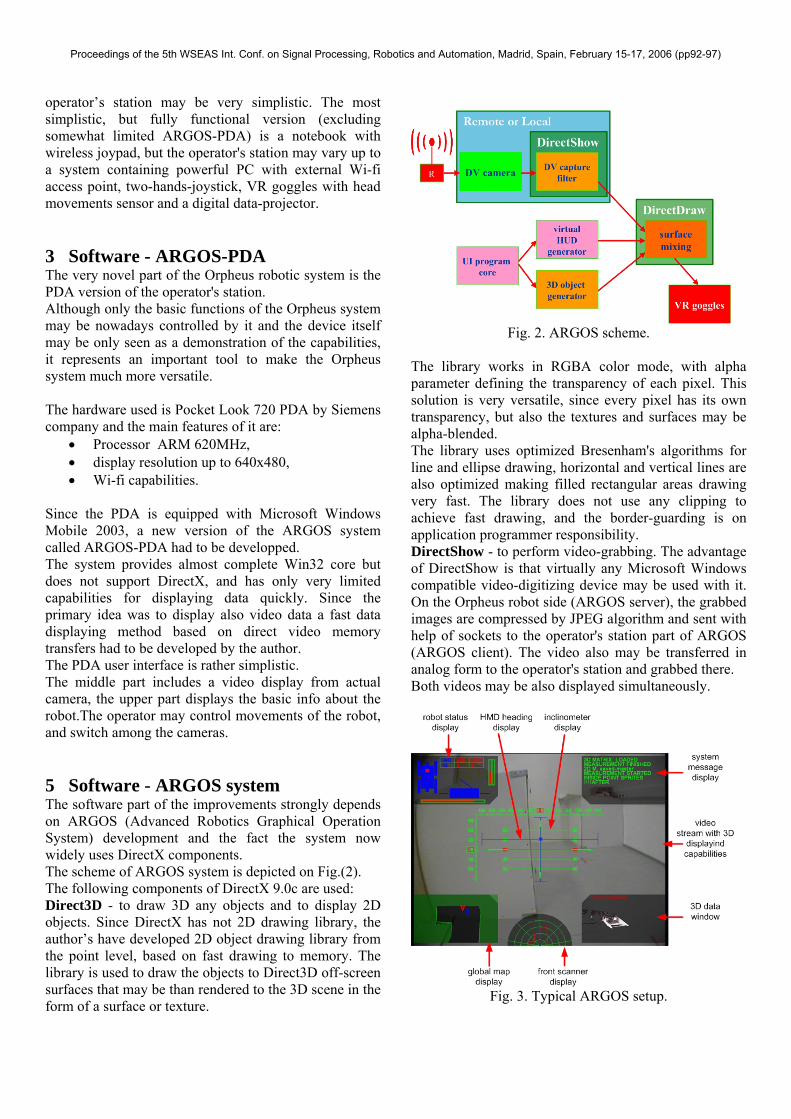
Fig. 3. Typical ARGOS setup.
Proceedings of the 5th WSEAS Int. Conf. on Signal Processing, Robotics and Automation, Madrid, Spain, February 15-17, 2006 (pp92-97)

Fig. 4. Photo taken by the competition
organizers from Robocup Rescue League 2003.
DirectInput - to process the data from human-machine interface devices like various joysticks and two-hands joystick systems, head movement sensors, etc. DirectSound - is used to play the voice messages that inform the operator about vital events that happen during operation. A very important issue is that video is rendered to DirectX surfaces. It means virtually any (even 3D) object may be covered by this surface what gives us a big potential for video data fusion tests. The video rendering is also under full programmer's control in this case. The second important feature is that any combination of 2D and 3D objects may be displayed. It means 3D data may be displayed not only in small vHUD's but also over the main screen. The advantage is also that DirectX has good support for alpha blending, so transparency may be easily defined for each object (in 3D) and even each pixel (in 2D). It is also possible to combine more video-images in the form of layers, again with transparency defined for each pixel. This feature is used for CCD camera and thermovision camera image data fusion, described below. ARGOS system is meant to be a universal solution to build high-performance user interfaces. The universality means, virtually any configuration of videos and data displays is possible. During the U.T.A.R. and Orpheus robot systems development authors tend to make a user interface convenient for most missions, that does not disturb the operator, but helps him to achieve the necessary data quickly and in well arranged form.
The final setup will be described in following text and a screenshot from it is on Fig. 3. This set-up has been consulted with many researchers involved in rescue robotics and it seems this arrangement is widely accepted by most of the people, although surely not definitive. 6 Inclination measurement and its
integration to user interface The first version of robotic system Orpheus was tested during five days of world competition - Robocup Rescue League 2003 in Padova, Italy. Although the overall performance of the Orpheus system and its user interface was good (the team won the competition), several limitations were found on it. The biggest problem related to the environment awareness of the operator seems to be the lack of information about the platform inclination. It seems the operator cannot rely only on the visual information because of a combination of several circumstances, where the most important one is the fact the perspective of the view is strongly distorted and the operator has very limited possibility to guess the distances in the scene. The system does not have stereovision, the image resolution and quality is quite low, the field of view is limited (compared to the human one). It also has to be considered the rescue robot environment may be very complicated (collapsed buildings, ruins) so it may happen that there are not any typical static orientation objects in the scene (walls, floor, ceiling) while the movable objects may be disoriented (tables, chairs).
Fig. 5. Central HUD.
INCLINATION
REFERENCE CROSS
HEAD ROTATION
ARTIFICIAL HORIZON
Proceedings of the 5th WSEAS Int. Conf. on Signal Processing, Robotics and Automation, Madrid, Spain, February 15-17, 2006 (pp92-97)

The mentioned facts lead to the conclusion that the operator does not have sufficient visual information of the robot inclination which may even endanger the whole mission due to possibility of robot overturn (see Fig.(4). From the above mentioned facts comes out that the operator cannot rely only on the visual data from the robot and it is useful to provide the inclination data to the user interface. So the Orpheus-X2 is equipped with 2DOF accelerometer ADXL202 that works as inclinometer and measures inclination in front-to-back and left-to-right orientation. The data from it are expressed by central VHUD. 7 User Interface Description As it was previously said, the user interface for telepresence control consists of a video on background and several displays over it. The displays will be described now. 7.1 Inertial Data - Central VHUD The central part of the operator’s view is called Central VHUD and contains the most important data for the operator’s instant orientation. Note this is the only VHUD that is not in dark box – it is both because if its importance and placement to the central (and most important) part of camera view. The data displayed by Central VHUD may be described according to Fig.(5). The Reference Cross forms base point to which all the other data are related. Head rotation cross is painted by blue ink and represents operator’s head relative rotation according to the central point. Although it may seem to be useless (since the operator normally knows where he is looking to…) it appears to be a very useful tool during mission. There are two reasons for it:
• The first reason is that the perspective in the VR glasses is distorted and the camera viewing angle does not correspond to the one of the VR glasses. The VR glasses used (I-Glasses SVGA 3D) have viewing angle less than 30º. But if a camera with lens with the corresponding angle would be used, the operator would see only very narrow portion of his/her surrounding, which would make the exploration much less efficient. So it is widely used practice, that the used camera has much wider lens (110 º in our case).
• The second reason why the head rotation display is important, is the inaccuracy of the head movement measurement. The InterTrax 2 is a very precise sensor for short term measurements, but it suffers by significant drift over longer (minutes) time periods. So it may happen that
the measured value does not correspond to the real head movement of the operator.
The Head rotation cross is also important when the camera movements are controlled by joystick instead of VR goggles (due to limited space for operator’s station, etc.). The second important information displayed in Central VHUD is robot body inclination. Since the operator needs both precise values of the inclination (e.g. when climbing a longer ramp) and analog-type of interpretation for fast orientation (e.g. when passing obstacle) during the mission, they are both provided. The faster and more intuitive version is called Artificial Horizon and has very similar function as in airplanes. The display is formed by series of lines that may rotate according to robot’s left-to-right inclination and move up and down according to robots front-to-back inclination. The precise robot inclinations are represented by numbered slide-bars on top and left of Central VHUD. The real ARGOS output that is seen in the VR goggles is on Fig.(6). Here the front camera of the robot points directly in front of robot (it is centered despite the operator’s head rotation) and the whole Orpheus robot body is strongly inclined to demonstrate the Artificial Horizon function of Central VHUD. 7.2 2D scan displays Laser scanner data from actual 2D measurement may be easily displayed to the user interface display in the form of small circular nets representing the polar distances from the sensor (see the central upper and lower circular parts of the user interface display on Fig.(6)). Although this display is very informative, it only shows one 2D scan from the scanner at a time.
Fig. 6. Screenshot from ARGOS
Proceedings of the 5th WSEAS Int. Conf. on Signal Processing, Robotics and Automation, Madrid, Spain, February 15-17, 2006 (pp92-97)

7.3 3D scan display To increase the information value, 3D representation of the proximity data is suitable. The right-lower display is used for 3D data representation. In the actual version of ARGOS it may be used to display so called instant data (what means actual 3D measurement from the proximity scanner), or data from 3D evidence grids. If the instant data are displayed, the data are recalculated from the original proximity scanner coordinates by Eq.(1-3).
xi,j = r*cos(α) (1) yi,j = r*sin(α)*cos(β) (2) zi,j = r*sin(α)*sin(β) (3) where α - horizontal angle of
measurement β - vertical angle of measurement
(rotation of the whole 2D scanner) r - measured distance
Note the rα plane is related to the 2D scanner and rotates with it vertically with β angle. The data are than rendered to a surface by Direct3D, while each distance measurement (or each cell of robot evidence grids – see below) is represented by a box or by a point-sprite. The box representation of 3D data is suitable mostly in cases when 3D evidence grids are displayed. Point sprites need much less computational power than boxes, since only one vertex is needed to define them. They are more suitable for instant 3D measurement representation. Their disadvantage is that only new graphical adapters support them, and without hardware support they cannot be rendered. If 3D grids are displayed, the data do not need to be recalculated, only scaling and homogeneous transformations are necessary. Since the whole scene is on a Direct3D surface, it may be easily integrated to the operator’s view (see right-lower part of ARGOS user interface in Fig.(3) or (6)). The same data may be also displayed over the main surface, it means they may appear to be on the camera image, what is valuable for data fusion calibration and demonstration of its features. 7.4 2D map display The left-lower display of ARGOS user interface is intended as 2D map display. In the current version it displays 2D evidence grids built by SLAM algorithm named HAYAI working with proximity laser scanner data.
7.5 System message display The right-upper vHUD serves as a message display and its function is the same as the one of first version of Orpheus user interface. It works as a log window and displays events that happen only once (e.g. warning messages, etc.). It appears as an infinite rolling paper with messages, and it is not suitable to display varying variables. The messages may have different colors according their priority. 7.5 Robot status display The status of the robot is displayed on upper-left display. It shows the most important status variables related to tobot's mechanics and electroncics. It informs operator if the robot is moving and what is the direction and speed of the motors. It also shows how the 2DOF arm is extended, which camera is active, and how the proximity scanners are oriented. There are also user interface-related pointers (if the HMD is active, if the arm control is activated, etc.) and it also contains actual data-flow bandwith over Ethernet connection. 8 H.O.T.A.S. - Hands on Throttle and Stick In ARGOS, the movements of the whole robot and all of the other functions may be controlled by advanced two-hands joystick system. This concept is known as Hands on Throttle and Stick (H.O.T.A.S.) and is known from supersonic fighter planes. The basic idea of H.O.T.A.S. concept is that the operator controls all functions of the device by the two-hands joystick, consisting of stick (held in right hand) and throttle (held in left hand), and does not need to use any other control devices like mouse or keyboard during the mission. This saves time and let the operator to concentrate to the situation rather than to the control of robot. The joystick system must be ergonomically designed to allow to use all the buttons and analog axes without hand position change. This is vital namely on right-hand joystick, because that is commonly used to control the movements of robot body and it may be dangerous if the operator loses control of it even for a short moment. In Orpheus system two two-hands joystick were used and tested. It has to be said that to control all the functions of the robot and ARGOS, the operator has to train a bit, but once he/she is trained, the control becomes much faster and certain.
Proceedings of the 5th WSEAS Int. Conf. on Signal Processing, Robotics and Automation, Madrid, Spain, February 15-17, 2006 (pp92-97)

Fig. 7. Data fusion – CCD Camera and thermovision.
4 Conclusion The telepresence controlled robot Orpheus-X2 with its control program ARGOS was described. The possibilities of it, as well as one typical configuration, used many times by the authors for tests and demonstrations, was described. From the test of the user interface made by the authors on a test group of 11 people it is evident the user interface and style of control is acceptable also for people that are not involved in robotics and even do not know the Orpheus robotic system. The test people received only 10 minutes long presentation about Orpheus and had 10 minutes to train to control it. Afterwards they had to go through a maze that they could not see before. Only one person from the test group had difficulties to fulfill this task. It has to be pointed out that the presented state-of-the-art of the user interface is not meant as definitive by the authors and development of it continues.
Fig. 8. Data fusion – CCD Camera and 3D scanner.
The current problem being solved on Orpheus-X2 with ARGOS is data fusion from three sensors – thermovision camera, CCD color camera and 3D proximity scanner. The 2D and 3D capabilities of ARGOS are very advantageous for development, testing and practical realization of it. All the data processing and displaying is done in real-time, all the changes give instant results. See Fig. (7) and (8) for screenshots from ARGOS doing data fusion. References: [1] Neuzil, T., Kopecny, L., Zalud, L. (2002).
Vision System of Universal Telepresence and Autonomous Robot. In: The 12th International Danube Adria Association for Automation & Manufacturing Symposium, pp 323-324, Jena, Germany.
[2] Zalud L. (2001). Universal Autonomous and Telepresence Mobile Robot Navigation. In: 32nd International Symposium on Robotics - ISR 2001, pp 1010-1015, Seoul, Korea.
[3] Zalud L., Kopecny L., Neuzil T. (2002). Laser Proximity Scanner Correlation Based Method for Cooperative Localization and Map Building. In: Proc. 7th International Workshop on Advanced Motion Control. Maribor, pp 480-486 University of Maribor, Slovenia.
[4] Everett, H.R., (1995). Sensors for Mobile Robots, Theory and Applications, AK Peters, Ltd., USA, ISBN: 1-56881-048-2.
[5] Martin C. M., Moravec H. P. (1996). Robot Evidence Grids, The Robotics Institute Carnegie Melon University, Pittsburgh, Pennsylvania 15213.
[6] Neuzil, T., Kopecny, L., Zalud, L. (2002). Vision System of Universal Telepresence and Autonomous Robot. In: The 12th International Danube Adria Association for Automation & Manufacturing Symposium, pp 323-324, Jena, Germany.
[7] Oyama, E., Tsunemoto, N., Tachi, S., Inoue, S. (1993). Experimental Study on Remote Manipulation using Virtual Reality. Presence, Volume 2 Number 2, pp 112-124.
[8] Sheridan, T.B., (1992). Telerobotics, Automation, and Human Supervisory Control, MIT Press, Cambridge, USA.
[9] Wise, E., (1999). Applied Robotics, Prompt Publications, USA, ISBN: 0-7906-1184-8.
[10] Zalud L. (2001). Universal Autonomous and Telepresence Mobile Robot Navigation. In: 32nd International Symposium on Robotics - ISR 2001, pp 1010-1015, Seoul, Korea.
[11] Zalud L. (2005). ORPHEUS – Reconniaissance Teleoperated Robotic System. In: 16th IFAC World Congress. pp. 1-6, Prague, Czech Republic
Proceedings of the 5th WSEAS Int. Conf. on Signal Processing, Robotics and Automation, Madrid, Spain, February 15-17, 2006 (pp92-97)