arduino wireless communication – nrf24l01...
TRANSCRIPT

Arduino Wireless Communication – NRF24L01 TutorialDejan NedelkovskiArduino Tutorials36In this Arduino tutorial we will learn how to make a wireless communication between twoArduino boards using the NRF24L01 transceiver module. You can watch the following video or read the written tutorial below.
Overview
For explaining the wireless communication we will make two examples, the first one will besending a simple “Hello World” message from one Arduino to another, and in the second example we will have a bi-directional communication between the Arduino boards, where using the Joystick at the first Arduino we will control the servo motor at the second Arduino, and vice versa, using the push button at the second Arduino we will control the LED at the first Arduino.
NRF24L01 Transceiver Module
Let’s take a closer look at the NRF24L01 transceiver module. It uses the 2.4 GHz band and it can operate with baud rates from 250 kbps up to 2 Mbps. If used in open space and with lower baud rate its range can reach up to 100 meters.

The module can use 125 different channels which gives a possibility to have a network of 125 independently working modems in one place. Each channel can have up to 6 addresses, or each unit can communicate with up to 6 other units at the same time.
The power consumption of this module is just around 12mA during transmission, which is even lower than a single LED. The operating voltage of the module is from 1.9 to 3.6V, but the good thing is that the other pins tolerate 5V logic, so we can easily connect it to an Arduino without using any logic level converters.
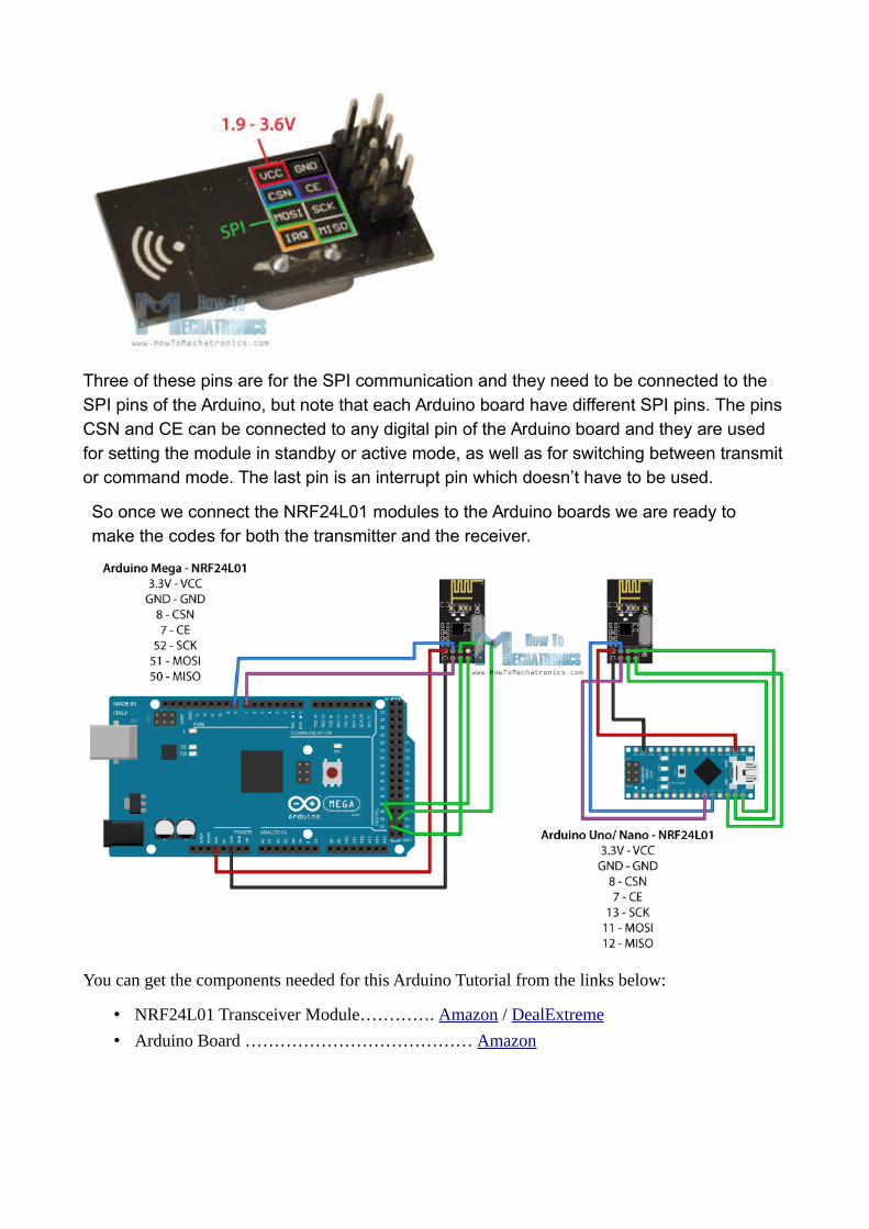
Three of these pins are for the SPI communication and they need to be connected to the SPI pins of the Arduino, but note that each Arduino board have different SPI pins. The pinsCSN and CE can be connected to any digital pin of the Arduino board and they are used for setting the module in standby or active mode, as well as for switching between transmitor command mode. The last pin is an interrupt pin which doesn’t have to be used.
So once we connect the NRF24L01 modules to the Arduino boards we are ready to make the codes for both the transmitter and the receiver.
You can get the components needed for this Arduino Tutorial from the links below:
• NRF24L01 Transceiver Module…………. Amazon / DealExtreme
• Arduino Board ………………………………… Amazon
Arduino Codes
First we need to download and install the RF24 library which makes the programming less difficult.
Here are the two codes for the wireless communication and below is the description of them.
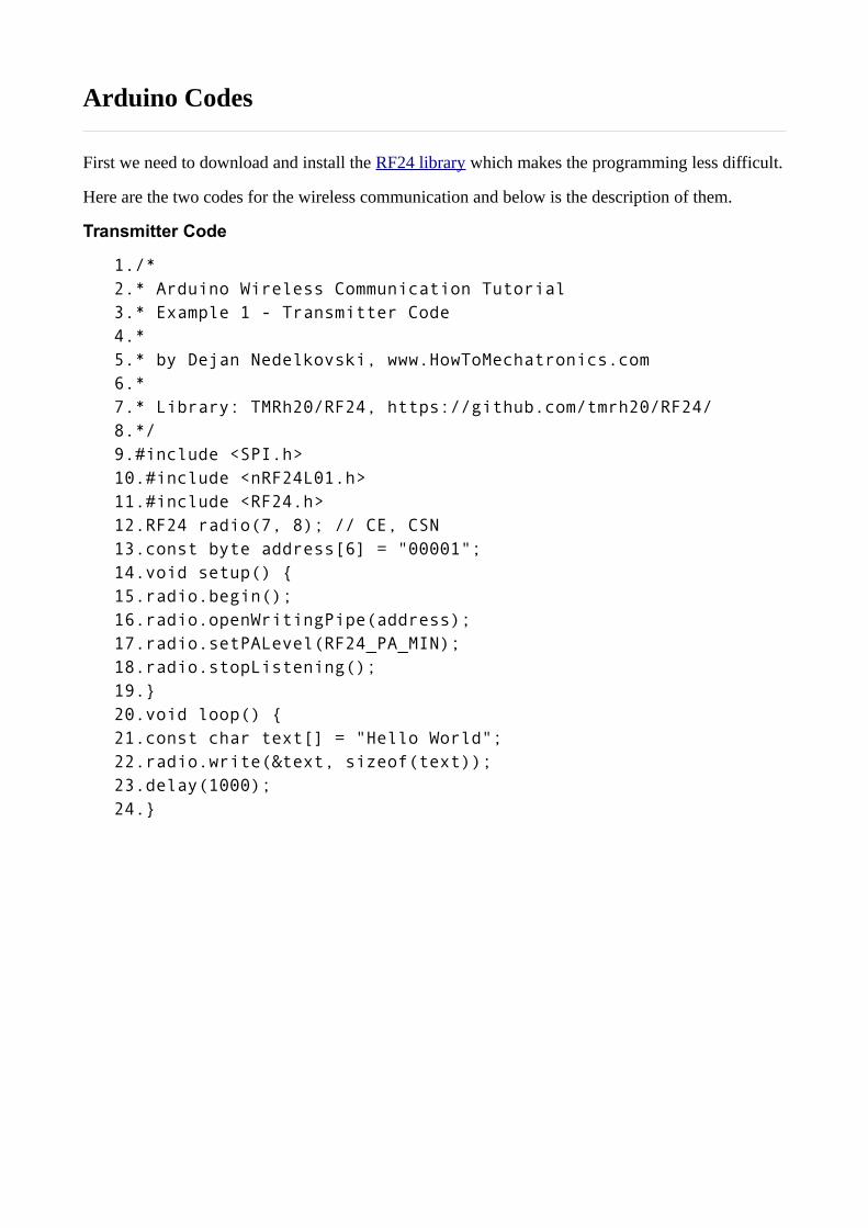
Transmitter Code
1./*2.* Arduino Wireless Communication Tutorial3.* Example 1 - Transmitter Code4.* 5.* by Dejan Nedelkovski, www.HowToMechatronics.com6.* 7.* Library: TMRh20/RF24, https://github.com/tmrh20/RF24/8.*/9.#include <SPI.h>10.#include <nRF24L01.h>11.#include <RF24.h>12.RF24 radio(7, 8); // CE, CSN13.const byte address[6] = "00001";14.void setup() {15.radio.begin();16.radio.openWritingPipe(address);17.radio.setPALevel(RF24_PA_MIN);18.radio.stopListening();19.}20.void loop() {21.const char text[] = "Hello World";22.radio.write(&text, sizeof(text));23.delay(1000);24.}

Receiver Code
1./*2.* Arduino Wireless Communication Tutorial3.* Example 1 - Receiver Code4.* 5.* by Dejan Nedelkovski, www.HowToMechatronics.com6.* 7.* Library: TMRh20/RF24, https://github.com/tmrh20/RF24/8.*/9.#include <SPI.h>10.#include <nRF24L01.h>11.#include <RF24.h>12.RF24 radio(7, 8); // CE, CSN13.const byte address[6] = "00001";14.void setup() {15.Serial.begin(9600);16.radio.begin();17.radio.openReadingPipe(0, address);18.radio.setPALevel(RF24_PA_MIN);19.radio.startListening();20.}21.void loop() {22.if (radio.available()) {23.char text[32] = "";24.radio.read(&text, sizeof(text));25.Serial.println(text);26.}27.}

Description:
So we need to include the basic SPI and the newly installed RF24 libraries and create an RF24 object. The two arguments here are the CSN and CE pins.
1.RF24 radio(7, 8); // CE, CSN
Next we need to create a byte array which will represent the address, or the so called pipe through which the two modules will communicate.
1.const byte address[6] = "00001";
We can change the value of this address to any 5 letter string and this enables to choose to which receiver we will talk, so in our case we will have the same address at both the receiver and the transmitter.
In the setup section we need to initialize the radio object and using the radio.openWritingPipe() function we set the address of the receiver to which we will send data, the 5 letter string we previously set.
1.radio.openWritingPipe(address);
On the other side, at the receiver, using the radio.setReadingPipe() function we set the same address and in that way we enable the communication between the two modules.
1.radio.openReadingPipe(0, address);
Then using the radio.setPALevel() function we set the Power Amplifier level, in our case I will set it to minimum as my modules are very close to each other.
1.radio.setPALevel(RF24_PA_MIN);
Note that if using a higher level it is recommended to use a bypass capacitors across GNDand 3.3V of the modules so that they have more stable voltage while operating.
Next we have the radio.stopListening() function which sets module as transmitter, and on the other side, we have the radio.startListening() function which sets the module as receiver.
1.// at the Transmitter2.radio.stopListening();
1.// at the Receiver2.radio.startListening();
In the loop section, at the transmitter, we create an array of characters to which we assign the message “Hello World”. Using the radio.write() function we will send that message to the receiver. The first argument here is the variable that we want to be sent.
1.void loop() {2.const char text[] = "Hello World";3.radio.write(&text, sizeof(text));4.delay(1000);5.}

By using the “&” before the variable name we actually set an indicating of the variable that stores the data that we want to be sent and using the second argument we set the numberof bytes that we want to take from that variable. In this case the sizeof() function gets all bytes of the strings “text”. At the end of the program we will add 1 second delay.
On the other side, at the receiver, in the loop section using the radio.available() function we check whether there is data to be received. If that’s true, first we create an array of 32 elements, called “text”, in which we will save the incoming data.
1.void loop() {2.if (radio.available()) {3.char text[32] = "";4.radio.read(&text, sizeof(text));5.Serial.println(text);6.}7.}
Using the radion.read() function we read and store the data into the “text” variable. At the end we just print text on the serial monitor. So once we upload both programs, we can run the serial monitor at the receiver and we will notice the message “Hello World” gets printedeach second.
Arduino Wireless Bi-directional Communication
Let’s see the second example, a bi-directional wireless communication between two Arduino boards. Here’s the circuit schematics:
You can get the components needed for this example from the links below:
• NRF24L01 Transceiver Module…………. Amazon / DealExtreme

• Joystick Module ………………………………. Amazon
• Arduino Board ………………………………… Amazon
• Servo Motor ……………………………………. Amazon
• Pushbutton …………………………………….. Amazon
• LED ………………………………………………… Amazon

Source codes : Here are the two codes and below is the description of them.
Transmitter Code
1./*2.* Arduino Wireless Communication Tutorial3.* Example 2 - Transmitter Code4.* 5.* by Dejan Nedelkovski, www.HowToMechatronics.com6.* 7.* Library: TMRh20/RF24, https://github.com/tmrh20/RF24/8.*/9.#include <SPI.h>10.#include <nRF24L01.h>11.#include <RF24.h>12.#define led 1213.RF24 radio(7, 8); // CE, CSN14.const byte addresses[][6] = {"00001", "00002"};15.boolean buttonState = 0;16.void setup() {17.pinMode(12, OUTPUT);18.radio.begin();19.radio.openWritingPipe(addresses[1]); // 0000120.radio.openReadingPipe(1, addresses[0]); // 0000221.radio.setPALevel(RF24_PA_MIN);22.}23.void loop() {24.delay(5);25.radio.stopListening();26.int potValue = analogRead(A0);27.int angleValue = map(potValue, 0, 1023, 0, 180);28.radio.write(&angleValue, sizeof(angleValue));29.delay(5);30.radio.startListening();31.while (!radio.available());32.radio.read(&buttonState, sizeof(buttonState));33.if (buttonState == HIGH) {34.digitalWrite(led, HIGH);35.}36.else {37.digitalWrite(led, LOW);38.}39.}

Receiver Code
1./*2.* Arduino Wireless Communication Tutorial3.* Example 2 - Receiver Code4.* 5.* by Dejan Nedelkovski, www.HowToMechatronics.com6.* 7.* Library: TMRh20/RF24, https://github.com/tmrh20/RF24/8.*/9.#include <SPI.h>10.#include <nRF24L01.h>11.#include <RF24.h>12.#include <Servo.h>13.#define button 414.RF24 radio(7, 8); // CE, CSN15.const byte addresses[][6] = {"00001", "00002"};16.Servo myServo;17.boolean buttonState = 0;18.void setup() {19.pinMode(button, INPUT);20.myServo.attach(5);21.radio.begin();22.radio.openWritingPipe(addresses[0]); // 0000223.radio.openReadingPipe(1, addresses[1]); // 0000124.radio.setPALevel(RF24_PA_MIN);25.}26.void loop() {27.delay(5);28.radio.startListening();29.if ( radio.available()) {30.while (radio.available()) {31.int angleV = 0;32.radio.read(&angleV, sizeof(angleV));33.myServo.write(angleV);34.}35.delay(5);36.radio.stopListening();37.buttonState = digitalRead(button);38.radio.write(&buttonState, sizeof(buttonState));39.}40.}

What’s different here from the previous example is that we need to create two pipes or addresses for the bi-directional communication.
1.const byte addresses[][6] = {"00001", "00002"};
In the setup section we need to define both pipes, and note that the writing address at the first Arduino needs to be the reading address at the second Arduino, and vice versa, the reading address at the first Arduino needs to be the writing address at the second Arduino.
1.// at the Transmitter2.radio.openWritingPipe(addresses[1]); // 000013.radio.openReadingPipe(1, addresses[0]); // 00002
1.// at the Receiver2.radio.openWritingPipe(addresses[0]); // 000023.radio.openReadingPipe(1, addresses[1]); // 00001
In the loop section using the radio.stopListening() function we set the first Arduino as transmitter, read and map the value of Joystick from 0 to 180, and using the radio.write() function send the data to the receiver.
1.radio.stopListening();2.int potValue = analogRead(A0);3.int angleValue = map(potValue, 0, 1023, 0, 180);4.radio.write(&angleValue, sizeof(angleValue));
On the other side, using the radio.startListening() function we set the second Arduino as receiver and we check whether there is available data. While there is data available we willread it, save it to the “angleV” variable and then use that value to rotate the servo motor.
1.radio.startListening();2.if ( radio.available()) {3.while (radio.available()) {4.int angleV = 0;5.radio.read(&angleV, sizeof(angleV));6.myServo.write(angleV);7.}
Next, at the transmitter, we set the first Arduino as receiver and with an empty “while” loop we wait for the second Arduino the send data, and that’s the data for the state of the push button whether is pressed or not. If the button is pressed the LED will light up. So these process constantly repeats and both Arduino boards are constantly sending and receiving data.
Source : http://howtomechatronics.com/tutorials/arduino/arduino-wireless-communication-nrf24l01-tutorial/

These transceivers use the 2.4 GHz unlicensed band like many WiFi routers, BlueTooth, some cordless phones etc. The range is 2.400 to 2.525 Ghz which is 2400 to 2525 MHz (MegaHz). The nRF24L01 channel spacing is 1 Mhz which gives 125 possible channels numbered 0 .. 124. WiFi uses most of the lower channels and we suggest using the highest 25 channels for nRF24L01 projects.
Transceivers like these both send and receive data in 'packets' of several bytes at a time. There is built-in error correction and resending, and it is possible to have one unit communicate with up to 6 other similar units at the same time. The RF24 Network Library extends this to multiple 'layers' of interconnected transceivers.
These amazing low-cost units have a lot of internal complexity but some talented people have written Arduino libraries that make them easy to us. They all use the same pinout as shown in the following diagram, which is a TOP VIEW (Correction!):
Here are details of the Pinout and connections to Arduino (updated):
Signal RF Module
PIN
Cable
COLOR
Base Module
PIN
Arduino pin for
TMRh20
RF24 Library
Arduino pin for
RF24 Library
Arduino pin for
Mirf Library
MEGA2560pin
RF24 Library
Arduino Pin for
RH_NRF24
RadioHeadLibrary
MEGA2560 Pin for
RH_NRF24
RadioHead Library
GND 1 Brown GND GND GND * GND GND * GND * GND *
VCC 2 Red VCC 3.3 V 3.3V * 3.3V 3.3V * 3.3V * 3.3V *
CE 3 Orange CE 7 9 8 9 8 8
CSN 4 Yellow CSN 8 10 7 53 10 53
SCK 5 Green SCK 13 13 13 52 13 52
MOSI 6 Blue MO 11 11 11 51 11 51
MISO 7 Violet MI 12 12 12 50 12 50
IRQ 8 Gray IRQ - 2 per library N/C N/C
NOTE!! Most * problems with intermittent operation are because of insufficient current or electrical noise on the 3.3V Power supply. The MEGA is more of a problem with this.

Solution: ADD bypass capacitors across GND and 3.3V ON the radio modules or use the Base Modules shown above. One user said, "Just Solder a 100nF ceramic cap across thegnd and 3.3v pins direct on the nrf24l01+ modules!" Some have used a 1uF to 10uF capacitor.
• NOTE: Pin 8 IRQ is Unused by most software, but the RF24 library has an example
that utilizes it.
The COLOR is for optional color-coded flat cable such as THIS. Photos above show an example.
NOTE: These units VCC connection must go to 3.3V not 5.0V, although the Arduino itself may run at 5.0V and the signals will be OK. The NRF24L01+ IC is a 3.3V device, but its I/O pins are 5 V tolerant , which makes it easier to interface to Arduino/YourDuino.Arduino UNO and earlier versions have a 3.3V output that can run the low-power version of these modules (See Power Problems at the top of this page!), but the high-power versions must have a separate 3.3V supply or use a Base Module with a 3.3V regulator. The YourDuino RoboRED has a higher power 3.3V regulator and can be used to run the high-power Power Amplifier type module without a separate 3.3V regulator.
Source : https://arduino-info.wikispaces.com/Nrf24L01-2.4GHz-HowTo
