arduino - mesure de distance-capteur ultrason-a quick-start guide
TRANSCRIPT
MEASURING DISTANCES WITH AN ULTRASONIC SENSOR 104
5.2 Measuring Distances with an Ultrasonic Sensor
Measuring distances automatically and continuously comes in handy
in many situations. Think of a robot that autonomously tries to find
its way or of an automatic burglar alarm that rings a bell or calls the
police whenever someone is too near to your house or to the Mona Lisa.
All this is possible with Arduino. But before you can create that burglar
alarm or robot, you need to understand some key concepts.
Many different types of sensors for measuring distances are available,
and the Arduino plays well with most of them. Some sensors use ultra-
sound, while others use infrared light or even laser. But in principle
all sensors work the same way: they emit a signal, wait for the echo to
return, and measure the time the whole process took. Because we know
how fast sound and light travel through the air, we can then convert the
measured time into a distance.
In our first project, we will build a device that measures the distance
to the nearest object and outputs it on the serial port. For this project,
we use the Parallax PING))) ultrasonic sensor,2 because it’s easy to use,
comes with excellent documentation, and has a nice feature set. It can
detect objects in a range between 2 centimeters and 3 meters, and we
use it directly with a breadboard, so we do not have to solder. It’s also a
perfect example of a sensor that provides information via variable-width
pulses (more on that in a few paragraphs). With the PING))) sensor, we
can easily build a sonar or a robot that automatically finds its way
through a maze without touching a wall.
As mentioned earlier, ultrasonic sensors usually do not return the dis-
tance to the nearest object. Instead, they return the time the sound
needed to travel to the object and back to the sensor. The PING))) is no
exception (see Figure 5.2, on the next page), and its innards are fairly
complex. Fortunately, they are hidden behind three simple pins: power,
ground, and signal.
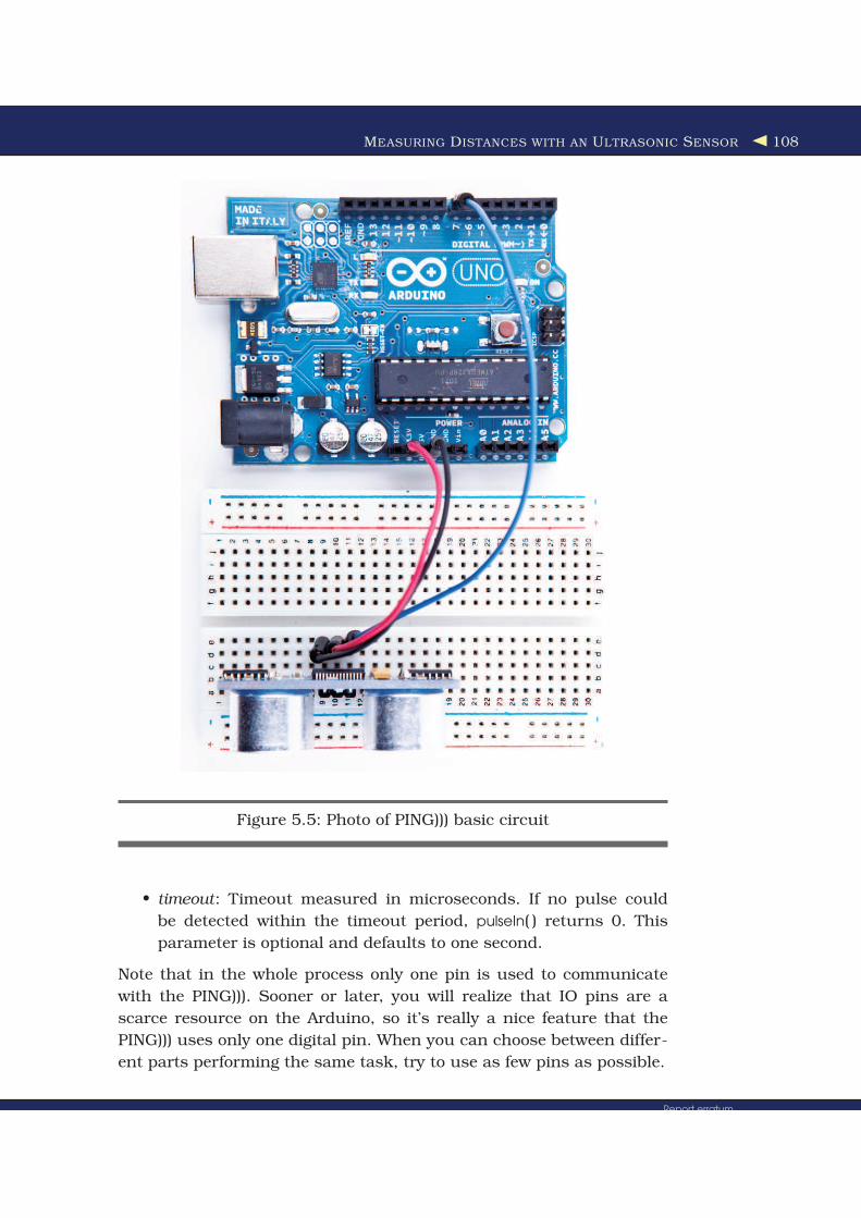
This makes it easy to connect the sensor to the Arduino. First, connect
Arduino’s ground and 5V power supply to the corresponding PING)))
pins. Then connect the PING)))’s sensor pin to one of the Arduino’s dig-
ital IO pins (we’re using pin 7 for no particular reason). For a diagram
of our circuit, see Figure 5.3, on the following page, and for a photo see
Figure 5.5, on page 108.
2. http://www.parallax.com/StoreSearchResults/tabid/768/txtSearch/28015/List/0/SortField/4/ProductID/92/Default.aspx
Report erratumDownload from Wow! eBook <www.wowebook.com>

MEASURING DISTANCES WITH AN ULTRASONIC SENSOR 105
!"#$%&
&'($
Figure 5.2: Basic working principle of the PING))) sensor
Figure 5.3: PING))) basic circuit
Report erratumDownload from Wow! eBook <www.wowebook.com>

MEASURING DISTANCES WITH AN ULTRASONIC SENSOR 106
To bring the circuit to life, we need some code that communicates with
the PING))) sensor:
Download ultrasonic/simple/simple.pde
Line 1 const unsigned int PING_SENSOR_IO_PIN = 7;
- const unsigned int BAUD_RATE = 9600;
-
- void setup() {
5 Serial.begin(BAUD_RATE);
- }
-
- void loop() {
- pinMode(PING_SENSOR_IO_PIN, OUTPUT);
10 digitalWrite(PING_SENSOR_IO_PIN, LOW);
- delayMicroseconds(2);
-
- digitalWrite(PING_SENSOR_IO_PIN, HIGH);
- delayMicroseconds(5);
15 digitalWrite(PING_SENSOR_IO_PIN, LOW);
-
- pinMode(PING_SENSOR_IO_PIN, INPUT);
- const unsigned long duration = pulseIn(PING_SENSOR_IO_PIN, HIGH);
- if (duration == 0) {
20 Serial.println("Warning: We did not get a pulse from sensor.");
- } else {
- Serial.print("Distance to nearest object: ");
- Serial.print(microseconds_to_cm(duration));
- Serial.println(" cm");
25 }
-
- delay(100);
- }
-
30 unsigned long microseconds_to_cm(const unsigned long microseconds) {
- return microseconds / 29 / 2;
- }
First we define a constant for the IO pin the PING))) sensor is connected
to. If you want to connect your sensor to another digital IO pin, you
have to change the program’s first line. In the setup( ) method, we set
the serial port’s baud rate to 9600, because we’d like to see some sensor
data on the serial monitor.
The real action happens in loop( ) where we actually implement the
PING))) protocol. According to the data sheet,3 we can control the sensor
using pulses, and it returns results as variable-width pulses, too.
3. http://www.parallax.com/dl/docs/prod/acc/28015-PING-v1.5.pdf
Report erratumDownload from Wow! eBook <www.wowebook.com>

MEASURING DISTANCES WITH AN ULTRASONIC SENSOR 107
Figure 5.4: PING))) pulse diagram
In lines 9 to 11, we set the sensor’s signal pin to LOW for 2 microsec-
onds to bring it to a proper state. This will ensure clean HIGH pulses
that are needed in the next steps (in the world of electronics, you should
always be prepared for jitters in the power supply).
Finally, it’s time to tell the sensor to do some work. In lines 13 to 15,
we set the sensor’s signal pin to HIGH for 5 microseconds to start a
new measurement. Afterward, we set the pin to LOW again, because
the sensor will respond with a HIGH pulse of variable length on the
same pin.
With a digital pin, you have only a few options to transmit information.
You can set the pin to HIGH or LOW, and you can control how long
it remains in a particular state. For many purposes, this is absolutely
sufficient, and in our case it is, too. When the PING))) sensor sends out
its 40 kHz chirp, it sets the signal pin to HIGH and then sets it back
to LOW when it receives the echo. That is, the signal pin remains in a
HIGH state for exactly the time it takes the sound to travel to an object
and back to the sensor. Loosely speaking, we are using a digital pin
for measuring an analog signal. In Figure 5.4, you can see a diagram
showing typical activity on a digital pin connected to a PING))) sensor.
We could measure the duration the pin remains in HIGH state manu-
ally, but the pulseIn( ) method already does all the dirty work for us. So,
we use it in line 18 after we have set the signal pin into input mode
again. pulseIn( ) accepts three parameters:
• pin: Number of the pin to read the pulse from.
• type: Type of the pulse that should be read. It can be HIGH or
LOW.
Report erratumDownload from Wow! eBook <www.wowebook.com>
MEASURING DISTANCES WITH AN ULTRASONIC SENSOR 108
Figure 5.5: Photo of PING))) basic circuit
• timeout: Timeout measured in microseconds. If no pulse could
be detected within the timeout period, pulseIn( ) returns 0. This
parameter is optional and defaults to one second.
Note that in the whole process only one pin is used to communicate
with the PING))). Sooner or later, you will realize that IO pins are a
scarce resource on the Arduino, so it’s really a nice feature that the
PING))) uses only one digital pin. When you can choose between differ-
ent parts performing the same task, try to use as few pins as possible.
Report erratumDownload from Wow! eBook <www.wowebook.com>

MEASURING DISTANCES WITH AN ULTRASONIC SENSOR 109
We have only one thing left to do: convert the duration we have mea-
sured into a length. Sound travels at 343 meters per second, which
means it needs 29.155 microseconds per centimeter. So, we have to
divide the duration by 29 and then by 2, because the sound has to
travel the distance twice. It travels to the object and then back to the
PING))) sensor. The microseconds_to_cm( ) method performs the calcula-
tion.
According to the specification of the PING))) sensor, you have to wait
at least 200 microseconds between two measurements. For high-speed
measurements, we could calculate the length of a pause more accu-
rately by actually measuring the time the code takes. But in our case,
this is pointless, because all the statements that are executed dur-
ing two measurements in the loop( ) method take far more than 200
microseconds. And outputting data to the serial connection is fairly
expensive. Despite this, we have added a small delay of 100 microsec-
onds to slow down the output a bit.
You might wonder why we use the const keyword so often. The Arduino
language is based on C/C++, and in these languages it’s considered a
good practice to declare constant values as const (see Effective C++: 50
Specific Ways to Improve Your Programs and Designs [Mey97]). Not only
will using const make your program more concise and prevent logical
errors early, it will also help the compiler to decrease your program’s
size.
Although most Arduino programs are comparatively small, software
development for the Arduino is still software development and should
be done according to all the best practices we know. So, whenever you
define a constant value in your program, declare it as such (using const,
not using #define). This is true for other programming languages, too,
so we will use final in our Processing and Java programs a lot (you’ll
learn more about Processing in Section 5.5, Transferring Data Back to
Your Computer Using Processing, on page 119).
Now it’s time to play around with the sensor and get familiar with
its strengths and weaknesses. Compile the program, upload it to your
Arduino board, and open the serial monitor (don’t forget to set the baud
rate to 9600). You should see something like this:
Distance to nearest object: 42 cm
Distance to nearest object: 33 cm
Distance to nearest object: 27 cm
Distance to nearest object: 27 cm
Report erratumDownload from Wow! eBook <www.wowebook.com>

INCREASING PRECISION USING FLOATING-POINT NUMBERS 110
Distance to nearest object: 29 cm
Distance to nearest object: 36 cm
In addition to the output in the terminal, you will see that the LED
on the PING))) sensor is turned on whenever the sensor starts a new
measurement.
Test the sensor’s capabilities by trying to detect big things or very small
things. Try to detect objects from different angles, and try to detect
objects that are below or above the sensor. You should also do some
experiments with objects that do not have a flat surface. Try to detect
stuffed animals, for example, and you will see that they are not detected
as well as solid objects (that’s probably the reason why bats don’t hunt
bears: they cannot see them).
With only three wires and a few lines of code, we have built a first
version of a digital metering rule. At the moment, it only outputs cen-
timeter distances in whole numbers, but we will increase its accuracy
tremendously in the next section by changing our software and adding
more hardware.
5.3 Increasing Precision Using Floating-Point Numbers
According to the specification, the PING))) sensor is accurate for objects
that are between 2 centimeters and 3 meters away. (By the way, the
reason for this is the length of the pulse that is generated. Its min-
imum length is 115 microseconds, and the maximum length is 18.5
milliseconds.) With our current approach, we do not fully benefit from
its precision because all calculations are performed using integer val-
ues. We can only measure distances with an accuracy of a centimeter.
To enter the millimeter range, we have to use floating-point numbers.
Normally it is a good idea to use integer operations, because compared
to regular computers the Arduino’s memory and CPU capacities are
severely limited and calculations containing floating-point numbers are
often expensive. But sometimes it’s useful to enjoy the luxury of highly
accurate floating-point numbers, and the Arduino supports them well.
We will use them to improve our project now:
Download ultrasonic/float/float.pde
Line 1 const unsigned int PING_SENSOR_IO_PIN = 7;
- const unsigned int BAUD_RATE = 9600;
- const float MICROSECONDS_PER_CM = 29.155;
- const float MOUNTING_GAP = 0.2;
Report erratumDownload from Wow! eBook <www.wowebook.com>
INCREASING PRECISION USING FLOATING-POINT NUMBERS 111
5 const float SENSOR_OFFSET = MOUNTING_GAP * MICROSECONDS_PER_CM * 2;
-
- void setup() {
- Serial.begin(BAUD_RATE);
- }
10
- void loop() {
- const unsigned long duration = measure_distance();
- if (duration == 0)
- Serial.println("Warning: We did not get a pulse from sensor.");
15 else
- output_distance(duration);
- }
-
- const float microseconds_to_cm(const unsigned long microseconds) {
20 const float net_distance = max(0, microseconds - SENSOR_OFFSET);
- return net_distance / MICROSECONDS_PER_CM / 2;
- }
-
- const unsigned long measure_distance() {
25 pinMode(PING_SENSOR_IO_PIN, OUTPUT);
- digitalWrite(PING_SENSOR_IO_PIN, LOW);
- delayMicroseconds(2);
-
- digitalWrite(PING_SENSOR_IO_PIN, HIGH);
30 delayMicroseconds(5);
- digitalWrite(PING_SENSOR_IO_PIN, LOW);
-
- pinMode(PING_SENSOR_IO_PIN, INPUT);
- return pulseIn(PING_SENSOR_IO_PIN, HIGH);
35 }
-
- void output_distance(const unsigned long duration) {
- Serial.print("Distance to nearest object: ");
- Serial.print(microseconds_to_cm(duration));
40 Serial.println(" cm");
- }
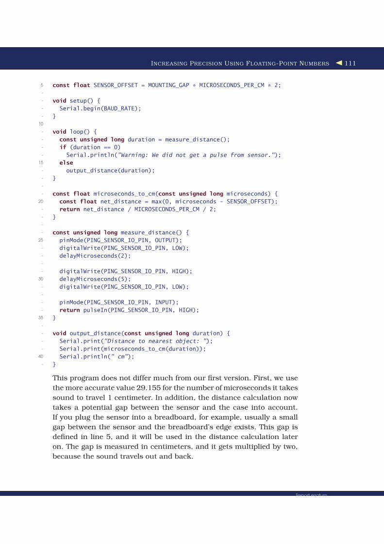
This program does not differ much from our first version. First, we use
the more accurate value 29.155 for the number of microseconds it takes
sound to travel 1 centimeter. In addition, the distance calculation now
takes a potential gap between the sensor and the case into account.
If you plug the sensor into a breadboard, for example, usually a small
gap between the sensor and the breadboard’s edge exists. This gap is
defined in line 5, and it will be used in the distance calculation later
on. The gap is measured in centimeters, and it gets multiplied by two,
because the sound travels out and back.
Report erratumDownload from Wow! eBook <www.wowebook.com>
INCREASING PRECISION USING FLOATING-POINT NUMBERS 112
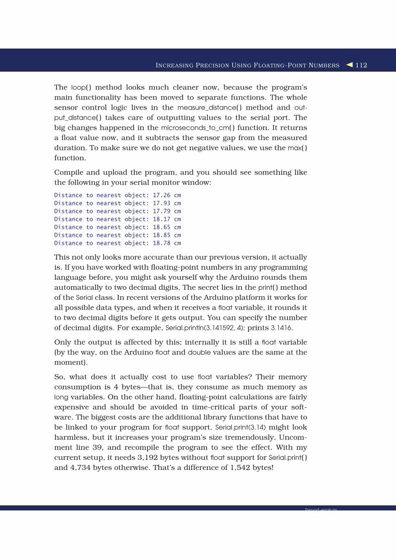
The loop( ) method looks much cleaner now, because the program’s
main functionality has been moved to separate functions. The whole
sensor control logic lives in the measure_distance( ) method and out-
put_distance( ) takes care of outputting values to the serial port. The
big changes happened in the microseconds_to_cm( ) function. It returns
a float value now, and it subtracts the sensor gap from the measured
duration. To make sure we do not get negative values, we use the max( )
function.
Compile and upload the program, and you should see something like
the following in your serial monitor window:
Distance to nearest object: 17.26 cm
Distance to nearest object: 17.93 cm
Distance to nearest object: 17.79 cm
Distance to nearest object: 18.17 cm
Distance to nearest object: 18.65 cm
Distance to nearest object: 18.85 cm
Distance to nearest object: 18.78 cm
This not only looks more accurate than our previous version, it actually
is. If you have worked with floating-point numbers in any programming
language before, you might ask yourself why the Arduino rounds them
automatically to two decimal digits. The secret lies in the print( ) method
of the Serial class. In recent versions of the Arduino platform it works for
all possible data types, and when it receives a float variable, it rounds it
to two decimal digits before it gets output. You can specify the number
of decimal digits. For example, Serial.println(3.141592, 4); prints 3.1416.
Only the output is affected by this; internally it is still a float variable
(by the way, on the Arduino float and double values are the same at the
moment).
So, what does it actually cost to use float variables? Their memory
consumption is 4 bytes—that is, they consume as much memory as
long variables. On the other hand, floating-point calculations are fairly
expensive and should be avoided in time-critical parts of your soft-
ware. The biggest costs are the additional library functions that have to
be linked to your program for float support. Serial.print(3.14) might look
harmless, but it increases your program’s size tremendously. Uncom-
ment line 39, and recompile the program to see the effect. With my
current setup, it needs 3,192 bytes without float support for Serial.print( )
and 4,734 bytes otherwise. That’s a difference of 1,542 bytes!
Report erratumDownload from Wow! eBook <www.wowebook.com>

INCREASING PRECISION USING A TEMPERATURE SENSOR 113
In some cases, you can still get the best of both worlds: float support
without paying the memory tax. You can save a lot of space by con-
verting the float values to integers before sending them over a serial
connection. To transfer values with a precision of two digits, multiply
them by 100, and do not forget to divide them by 100 on the receiving
side. We will use this trick (including rounding) later.
5.4 Increasing Precision Using a Temperature Sensor
Support for floating-point numbers is certainly an improvement, but
it mainly increases the precision of our program’s output. We could
have achieved a similar effect using some integer math tricks. But now
we will add an even better improvement that cannot be imitated using
software: a temperature sensor.
When I told you that sound travels through air at 343m/s, I wasn’t
totally accurate, because the speed of sound is not constant—among
other things it depends on the air’s temperature. If you do not take
temperature into account, the error can grow up to a quite significant
12 percent. We calculate the actual speed of sound C with a simple
formula:
C = 331.5 + (0.6 * t)
To use it, we only have to determine the current temperature t in Cel-
sius. We will use the TMP36 voltage output temperature sensor from
Analog Devices.4 It’s cheap, and it’s easy to use.
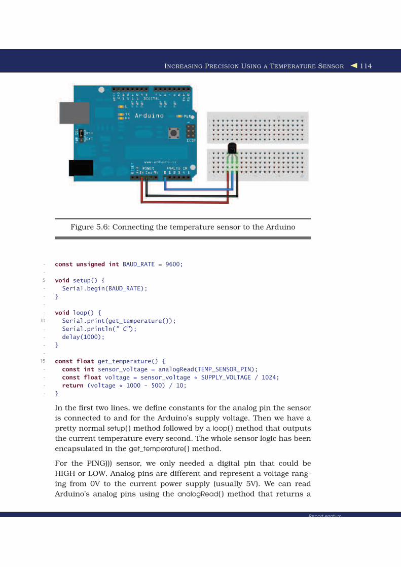
To connect the TMP36 to the Arduino, connect the Arduino’s ground
and power to the corresponding pins of the TMP36. Then connect the
sensor’s signal pin to the pin A0, that is, the analog pin number 0 (see
Figure 5.6, on the following page).
As you might have guessed from its vendor’s name, the TMP36 is an
analog device: it changes the voltage on its signal pin corresponding to
the current temperature. The higher the temperature, the higher the
voltage. For us it is an excellent opportunity to learn how to use the
Arduino’s analog IO pins. So, let’s see some code that uses the sensor:
Download temperature/sensortest/sensortest.pde
Line 1 const unsigned int TEMP_SENSOR_PIN = 0;
- const float SUPPLY_VOLTAGE = 5.0;
4. http://tinyurl.com/msard-analog
Report erratumDownload from Wow! eBook <www.wowebook.com>
INCREASING PRECISION USING A TEMPERATURE SENSOR 114
Figure 5.6: Connecting the temperature sensor to the Arduino
- const unsigned int BAUD_RATE = 9600;
-
5 void setup() {
- Serial.begin(BAUD_RATE);
- }
-
- void loop() {
10 Serial.print(get_temperature());
- Serial.println(" C");
- delay(1000);
- }
-
15 const float get_temperature() {
- const int sensor_voltage = analogRead(TEMP_SENSOR_PIN);
- const float voltage = sensor_voltage * SUPPLY_VOLTAGE / 1024;
- return (voltage * 1000 - 500) / 10;
- }
In the first two lines, we define constants for the analog pin the sensor
is connected to and for the Arduino’s supply voltage. Then we have a
pretty normal setup( ) method followed by a loop( ) method that outputs
the current temperature every second. The whole sensor logic has been
encapsulated in the get_temperature( ) method.
For the PING))) sensor, we only needed a digital pin that could be
HIGH or LOW. Analog pins are different and represent a voltage rang-
ing from 0V to the current power supply (usually 5V). We can read
Arduino’s analog pins using the analogRead( ) method that returns a
Report erratumDownload from Wow! eBook <www.wowebook.com>
INCREASING PRECISION USING A TEMPERATURE SENSOR 115
value between 0 and 1023, because analog pins have a resolution of
ten bits (1024 = 210). We use it in line 16 to read the current voltage
supplied by the TMP36.
There’s one problem left, though: we have to turn the value returned
by analogRead( ) into an actual voltage value, so we must know the
Arduino’s current power supply. It usually is 5V, but there are Arduino
models (the Arduino Pro, for example) that use only 3.3V. You have to
adjust the constant SUPPLY_VOLTAGE accordingly.
Knowing the supply voltage, we can turn the analog pin’s output into
a voltage value by dividing it by 1024 and by multiplying it with the
supply voltage afterward. That’s exactly what we do in line 17.
We now have to convert the voltage the sensor delivers into degree Cel-
sius. In the sensor’s data sheet, we find the following formula:
T = ((sensor output in mV) - 500) / 10
500 millivolts have to be subtracted, because the sensor always outputs
a positive voltage. This way, we can represent negative temperatures,
too. The sensor’s resolution is 10 millivolts, so we have to divide by 10.
A voltage value of 750 millivolts corresponds to a temperature of (750 -
500) / 10 = 25◦C, for example. See it implemented in line 18.
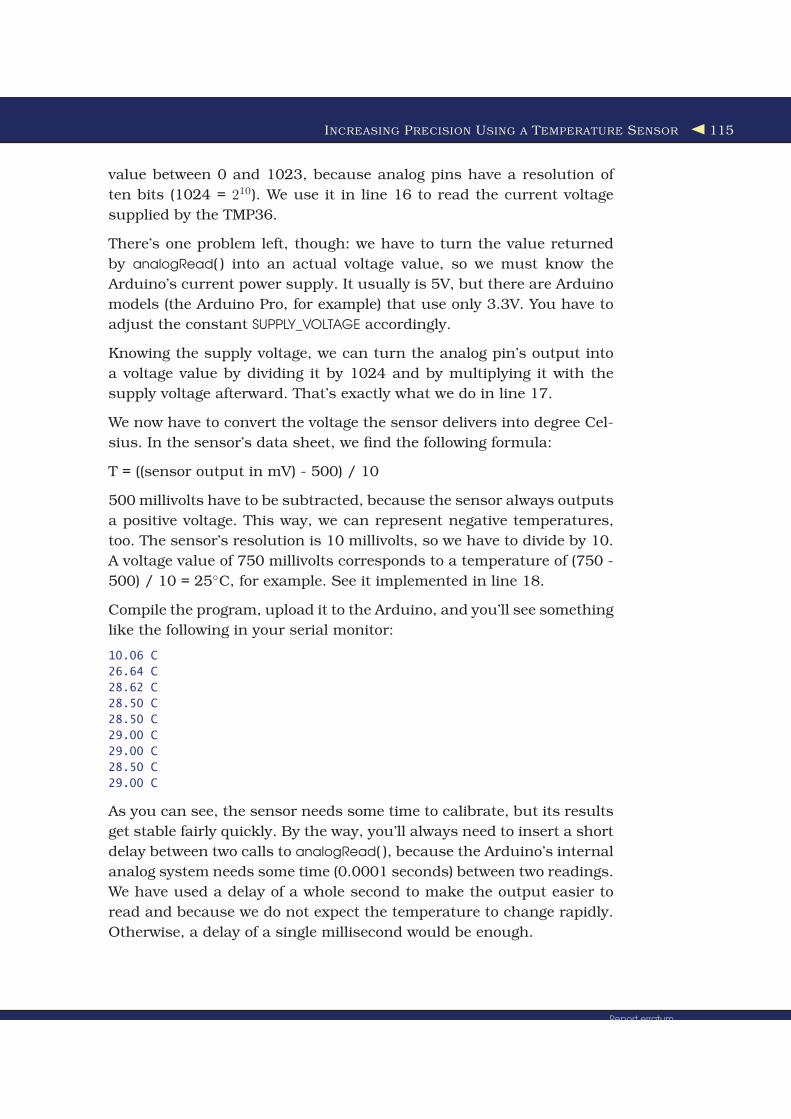
Compile the program, upload it to the Arduino, and you’ll see something
like the following in your serial monitor:
10.06 C
26.64 C
28.62 C
28.50 C
28.50 C
29.00 C
29.00 C
28.50 C
29.00 C
As you can see, the sensor needs some time to calibrate, but its results
get stable fairly quickly. By the way, you’ll always need to insert a short
delay between two calls to analogRead( ), because the Arduino’s internal
analog system needs some time (0.0001 seconds) between two readings.
We have used a delay of a whole second to make the output easier to
read and because we do not expect the temperature to change rapidly.
Otherwise, a delay of a single millisecond would be enough.
Report erratumDownload from Wow! eBook <www.wowebook.com>

INCREASING PRECISION USING A TEMPERATURE SENSOR 116
Figure 5.7: The TMP36 and the PING))) sensors working together
Now we have two separate circuits: one for measuring distances and
one for measuring temperatures. See them combined to a single circuit
in Figure 5.7, as well as in Figure 5.8, on page 120. Use the following
program to bring the circuit to life:
Download ultrasonic/PreciseSensor/PreciseSensor.pde
Line 1 const unsigned int TEMP_SENSOR_PIN = 0;
- const float SUPPLY_VOLTAGE = 5.0;
- const unsigned int PING_SENSOR_IO_PIN = 7;
- const float SENSOR_GAP = 0.2;
5 const unsigned int BAUD_RATE = 9600;
-
- float current_temperature = 0.0;
Report erratumDownload from Wow! eBook <www.wowebook.com>

INCREASING PRECISION USING A TEMPERATURE SENSOR 117
- unsigned long last_measurement = millis();
-
10 void setup() {
- Serial.begin(BAUD_RATE);
- }
-
- void loop() {
15 unsigned long current_millis = millis();
- if (abs(current_millis - last_measurement) >= 1000) {
- current_temperature = get_temperature();
- last_measurement = current_millis;
- }
20 Serial.print(scaled_value(current_temperature));
- Serial.print(",");
- const unsigned long duration = measure_distance();
- Serial.println(scaled_value(microseconds_to_cm(duration)));
- }
25
- long scaled_value(const float value) {
- float round_offset = value < 0 ? -0.5 : 0.5;
- return (long)(value * 100 + round_offset);
- }
30
- const float get_temperature() {
- const int sensor_voltage = analogRead(TEMP_SENSOR_PIN);
- const float voltage = sensor_voltage * SUPPLY_VOLTAGE / 1024;
- return (voltage * 1000 - 500) / 10;
35 }
-
- const float microseconds_per_cm() {
- return 1 / ((331.5 + (0.6 * current_temperature)) / 10000);
- }
40
- const float sensor_offset() {
- return SENSOR_GAP * microseconds_per_cm() * 2;
- }
-
45 const float microseconds_to_cm(const unsigned long microseconds) {
- const float net_distance = max(0, microseconds - sensor_offset());
- return net_distance / microseconds_per_cm() / 2;
- }
-
50 const unsigned long measure_distance() {
- pinMode(PING_SENSOR_IO_PIN, OUTPUT);
- digitalWrite(PING_SENSOR_IO_PIN, LOW);
- delayMicroseconds(2);
-
55 digitalWrite(PING_SENSOR_IO_PIN, HIGH);
- delayMicroseconds(5);
- digitalWrite(PING_SENSOR_IO_PIN, LOW);
-
Report erratumDownload from Wow! eBook <www.wowebook.com>

INCREASING PRECISION USING A TEMPERATURE SENSOR 118
- pinMode(PING_SENSOR_IO_PIN, INPUT);
60 return pulseIn(PING_SENSOR_IO_PIN, HIGH);
- }
The code is nearly a perfect merge of the programs we used to get
the PING))) and the TMP36 sensors working. Only a few things were
changed:
• The constant MICROSECONDS_PER_CM has been replaced by the
microseconds_per_cm( ) function that determines the microseconds
sound needs to travel 1 centimeter dynamically depending on the
current temperature.
• Because the current temperature will usually not change often
or rapidly, we no longer measure it permanently but only once a
second. We use millis( ) in line 8 to determine the number of mil-
liseconds that have passed since the Arduino started. From lines
15 to 19, we check whether more than a second has passed since
the last measurement. If yes, we measure the current temperature
again.
• We no longer transfer the sensor data as floating-point numbers
on the serial port but use scaled integer values instead. This is
done by the scaled_value( ) function that rounds a float value to two
decimal digits and converts it into a long value by multiplying it
by 100. On the receiving side, you have to divide it by 100 again.
If you upload the program to your Arduino and play around with your
hand in front of the sensor, you’ll see an output similar to the following:
1940,2818
2914,3032
3045,34156
3005,2843
3045,2476
3085,2414
The output is a comma-separated list of values where the first value
represents the current temperature in degree Celsius, and the second
is the distance to the nearest object measured in centimeters. Both
values have to be divided by 100 to get the actual sensor data.
Our little project now has two sensors. One is connected to a digital pin,
while the other uses an analog one. In the next section, you’ll learn how
to transfer sensor data back to a PC and use it to create applications
based on the current state of the real world.
Report erratumDownload from Wow! eBook <www.wowebook.com>

TRANSFERRING DATA BACK TO YOUR COMPUTER USING PROCESSING 119
How to Encode Sensor Data
Encoding sensor data is a problem that has to be solved oftenin Arduino projects, because all the nice data we collect usu-ally has to be interpreted by applications running on regularcomputers.
When defining a data format, you have to take several thingsinto account. For example, the format should not waste theArduino’s precious memory. In our case, we could have usedXML for encoding the sensor data, for example:
<sensor-data><temperature>30.05</temperature><distance>51.19</distance>
</sensor-data>
Obviously this is not a good choice, because now we are wast-ing a multiple of the actual data’s memory for creating the fileformat’s structure. In addition, the receiving application has touse an XML parser to interpret the data.
But you shouldn’t go to the other extreme either. That is, youshould use binary formats only if it’s absolutely necessary or ifthe receiving application expects binary data anyway.
All in all, the simplest data formats such as character-separatedvalues (CSV) are often the best choice.
5.5 Transferring Data Back to Your Computer Using Processing
All the programs in this chapter transfer sensor data back to your com-
puter using a serial port. But until now we’ve only watched the data
passing by in the IDE’s serial monitor and haven’t used it in our own
applications.
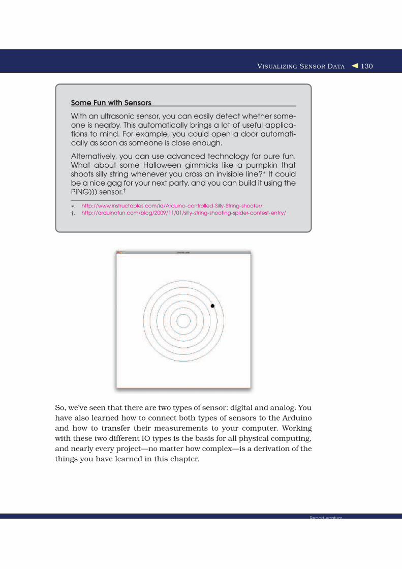
In this section, we will build an application that graphically visualizes
the sensor data. The program will implement a kind of inverted sonar:
it draws a small dot on the screen showing the distance to the nearest
object, while the position of the dot will move in a circle itself (see the
picture on page 130).
To implement the application, we’ll use the Processing programming
language, and in Figure 5.9, on page 121 you can see how we’ll organize
the project. The Processing code runs on our computer while all the
Report erratumDownload from Wow! eBook <www.wowebook.com>

TRANSFERRING DATA BACK TO YOUR COMPUTER USING PROCESSING 120
Figure 5.8: Photo of final circuit
Report erratumDownload from Wow! eBook <www.wowebook.com>

TRANSFERRING DATA BACK TO YOUR COMPUTER USING PROCESSING 121
Save the Climate Using Sonar Sensors
Researchers from Northwestern and University of Michiganhave created a sonar system that only uses a computer’smicrophone and speakers to detect whether the computer iscurrently used or not.∗ If it’s not being used, the computer auto-matically powers off its screen, saving the environment.
Instead of using a microphone and speakers, you can also usea PING))) sensor. With the lessons you’ve learned in this chapter,you can build such a system yourself with ease. Try it!
∗. http://blog.makezine.com/archive/2009/10/using_sonar_to_save_power.html
!"#$%&
!'(&)**+,-."(/)
0)'+%1.!('2
Figure 5.9: System architecture of our inverted Sonar project
PING))) sensor code still runs on the Arduino. Communication between
the Processing code and the Arduino happens via serial port.
Processing is an extension of the Java programming language, and its
focus is on computational art. With Processing, it’s very easy to cre-
ate multimedia applications: applications that produce sound and ani-
mated 2D or 3D graphics. It also has excellent support for user inter-
actions and is well documented (for example, see Processing: Creative
Coding and Computational Art [Gre07]).
Report erratumDownload from Wow! eBook <www.wowebook.com>

TRANSFERRING DATA BACK TO YOUR COMPUTER USING PROCESSING 122
Figure 5.10: The Processing IDE is the basis for the Arduino IDE.
It was originally built for design students who do not have a lot of
programming experience but who still wanted to use computers and
electronic devices to create interactive artwork. That’s the reason why
Processing is easy to learn and very beginner-friendly. But many peo-
ple also use it for serious and advanced tasks, especially for presenting
data in visually appealing ways.
You can download Processing for free,5 and it comes with a one-click
installer for all popular operating systems. Start it or take a look at Fig-
ure 5.10. Looks familiar, doesn’t it? That is not a coincidence, because
the Arduino IDE was derived from the Processing IDE. Instead of writ-
5. http://processing.org/download/
Report erratumDownload from Wow! eBook <www.wowebook.com>

REPRESENTING SENSOR DATA 123
ing a new programming environment from scratch, the Arduino team
decided to modify the Processing IDE. That’s the reason why both IDEs
look so similar and why Arduino sketches have the file extension .pde
(Processing Development Environment), for example.
Using Processing as the basis for the Arduino project provided a good
and well-tested IDE for free. Processing and the Arduino are a good
team for several other reasons:
• The Arduino simplifies embedded computing, and Processing sim-
plifies the creation of multimedia applications. So, you can easily
visualize sensor data in often spectacular ways.
• Processing is easy to learn, especially if you already know Java.
• Processing has excellent support for serial communication.
So, for many reasons, Processing is well worth a look, but it’s espe-
cially useful when working with the Arduino. That’s why we’ll use it for
several of the book’s examples.
5.6 Representing Sensor Data
We start with a Processing class that represents the current sensor
data we return from the Arduino via serial port. Open a new file in the
Processing IDE, and enter the following code:
Download ultrasonic/InvertedSonar/SensorData.pde
class SensorData {
private float temperature;
private float distance;
SensorData(float temperature, float distance) {
this.temperature = temperature;
this.distance = distance;
}
float getTemperature() {
return this.temperature;
}
float getDistance() {
return this.distance;
}
}
If you are familiar with Java or C++, the SensorData class will be per-
fectly clear to you. It encapsulates a temperature value and a distance
Report erratumDownload from Wow! eBook <www.wowebook.com>

REPRESENTING SENSOR DATA 124
as floating-point numbers and provides access to the data via accessor
methods (getTemperature( ) and getDistance( )). You can create new Sensor-
Data objects using the constructor, passing it the current temperature
and distance.
Processing is an object-oriented programming language and allows us
to define new classes using the class keyword. Classes have a name and
they contain data (often called attributes or properties) and functions
(often called methods). Our SensorData class contains two attributes
named temperature and distance. They are both of type float, and we
have declared them both private. Now only members of the SensorData
class are allowed to access them. This is considered good style, because
it prevents unwanted side effects and makes future changes much eas-
ier. A class should never expose its innards.
To set and get the values of our attributes, we have to use public meth-
ods, and our class has three of them: SensorData( ), getTemperature( ), and
getDistance( ). (Java and C++ programmers should note that in Process-
ing everything is public if not specified otherwise!) A method that has
the same name as the class is called a constructor, and you can use it
for creating and initializing new objects of that particular class. Con-
structors do not have return values, but they may specify parameters.
Ours, for example, takes two arguments and uses them to initialize our
two attributes.
There’s a small problem, though: our method’s parameters have the
same names as our classes’ attributes. What would happen if we simply
assigned the method parameters to the attributes like this:
temperature = temperature;
distance = distance;
Right: we simply assigned every method parameter to itself, which is
effectively a no-operation. That’s why we use the this keyword. It refers
to the class itself, so we can distinguish between the method parame-
ters and the classes’ attributes. Alternatively, we could have used dif-
ferent names for the method parameters or the attributes, but I prefer
to use this.
After the constructor, we define the methods getTemperature and getDis-
tance. Their definitions are very similar; we declare the method’s return
type (float), the method’s name, and a list of parameters in parentheses.
In our case, the parameter list is empty. In the methods, we return the
Report erratumDownload from Wow! eBook <www.wowebook.com>

BUILDING THE APPLICATION’S FOUNDATION 125
current value of the corresponding attributes using the return keyword.
return stops the method and returns its argument to the method’s caller.
Now we can create and initialize new SensorData objects:
SensorData sensorData = new SensorData(31.5, 11.76);
The previous statement creates a new SensorData object named sensor-
Data. It sets temperature to 31.5 and distance to 11.76. To read those
values, we use the corresponding “get” methods:
sensorData.getTemperature(); // -> 31.5
sensorData.getDistance(); // -> 11.76
Because getTemperature( ) and getDistance( ) are members of the Sensor-
Data class, you can only invoke them using an instance of the class.
Our instance is named sensorData, and to call the “get” methods we have
to use the instance name, followed by a dot, followed by the method
name.
Now that we can store sensor data, we’ll continue to build our inverted
sonar application in the next section.
5.7 Building the Application’s Foundation
In this section, we’ll create all the boilerplate code we need for our appli-
cation by importing some libraries and defining some global constants
and variables:
Download ultrasonic/InvertedSonar/InvertedSonar.pde
import processing.serial.*;
final int WIDTH = 1000;
final int HEIGHT = 1000;
final int xCenter = WIDTH / 2;
final int yCenter = HEIGHT / 2;
final int LINE_FEED = 10;
Serial arduinoPort;
SensorData sensorData;
int degree = 0;
int radius = 0;
To communicate with the Arduino via a serial port, we import Process-
ing’s support for serial communication in the first line. The import state-
ment imports all classes from the processing.serial package and makes
them available in our program.
Report erratumDownload from Wow! eBook <www.wowebook.com>
IMPLEMENTING SERIAL COMMUNICATION IN PROCESSING 126
Our application will have a 1000x1000 pixel screen, so we define con-
stants for its width, height, and its center. We set the LINE_FEED constant
to the ASCII value of a linefeed character, because we need it later to
interpret the data sent by the Arduino.
Then we define a few global variables (yes, you Java programmers out
there: Processing allows you to define global variables!):
• arduinoPort: An instance of Processing’s Serial class. It’s from the
processing.serial package we have imported and encapsulates the
serial port communication with the Arduino.
• sensorData: The current sensor data that have been transferred
from the Arduino to our application. We use the SensorData class
we defined in Section 5.6, Representing Sensor Data, on page 123.
• degree: We will visualize the current distance to the nearest object
on a circle. This variable stores on which degree of the circle we
are right now. Values range from 0 to 359.
• radius: The current distance to the nearest object is interpreted as
a radius value.
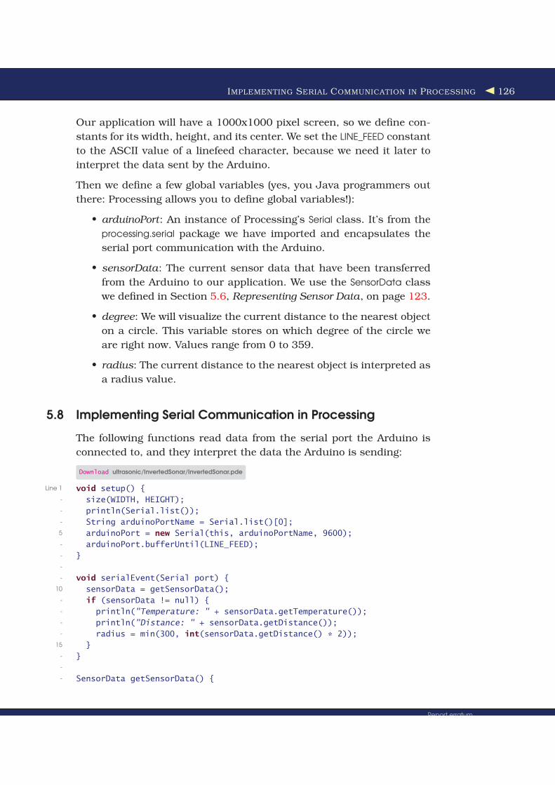
5.8 Implementing Serial Communication in Processing
The following functions read data from the serial port the Arduino is
connected to, and they interpret the data the Arduino is sending:
Download ultrasonic/InvertedSonar/InvertedSonar.pde
Line 1 void setup() {
- size(WIDTH, HEIGHT);
- println(Serial.list());
- String arduinoPortName = Serial.list()[0];
5 arduinoPort = new Serial(this, arduinoPortName, 9600);
- arduinoPort.bufferUntil(LINE_FEED);
- }
-
- void serialEvent(Serial port) {
10 sensorData = getSensorData();
- if (sensorData != null) {
- println("Temperature: " + sensorData.getTemperature());
- println("Distance: " + sensorData.getDistance());
- radius = min(300, int(sensorData.getDistance() * 2));
15 }
- }
-
- SensorData getSensorData() {
Report erratumDownload from Wow! eBook <www.wowebook.com>
IMPLEMENTING SERIAL COMMUNICATION IN PROCESSING 127
- SensorData result = null;
20 if (arduinoPort.available() > 0) {
- final String arduinoOutput = arduinoPort.readStringUntil(LINE_FEED);
- result = parseArduinoOutput(arduinoOutput);
- }
- return result;
25 }
-
- SensorData parseArduinoOutput(final String arduinoOutput) {
- SensorData result = null;
- if (arduinoOutput != null) {
30 final int[] data = int(split(trim(arduinoOutput), ','));
- if (data.length == 2)
- result = new SensorData(data[0] / 100.0, data[1] / 100.0);
- }
- return result;
35 }
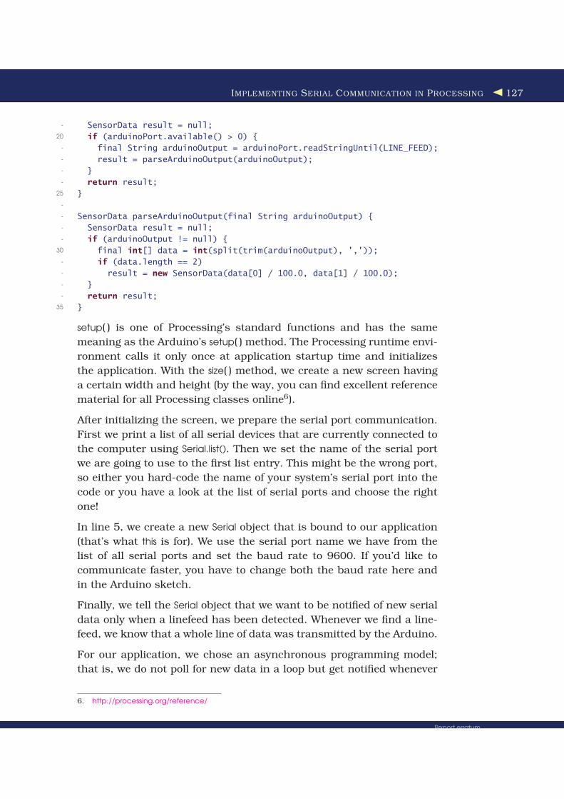
setup( ) is one of Processing’s standard functions and has the same
meaning as the Arduino’s setup( ) method. The Processing runtime envi-
ronment calls it only once at application startup time and initializes
the application. With the size( ) method, we create a new screen having
a certain width and height (by the way, you can find excellent reference
material for all Processing classes online6).
After initializing the screen, we prepare the serial port communication.
First we print a list of all serial devices that are currently connected to
the computer using Serial.list(). Then we set the name of the serial port
we are going to use to the first list entry. This might be the wrong port,
so either you hard-code the name of your system’s serial port into the
code or you have a look at the list of serial ports and choose the right
one!
In line 5, we create a new Serial object that is bound to our application
(that’s what this is for). We use the serial port name we have from the
list of all serial ports and set the baud rate to 9600. If you’d like to
communicate faster, you have to change both the baud rate here and
in the Arduino sketch.
Finally, we tell the Serial object that we want to be notified of new serial
data only when a linefeed has been detected. Whenever we find a line-
feed, we know that a whole line of data was transmitted by the Arduino.
For our application, we chose an asynchronous programming model;
that is, we do not poll for new data in a loop but get notified whenever
6. http://processing.org/reference/
Report erratumDownload from Wow! eBook <www.wowebook.com>

VISUALIZING SENSOR DATA 128
there’s new data on the serial port (to be concise, we want to be notified
only if a new linefeed was found). This way, we can change our applica-
tion’s state in real time and can prevent disturbing delays between the
arrival of data and graphics updates on the screen.
When new data arrives, serialEvent( ) gets called automatically and is
passed the serial port the data was found on. We have only one port,
so we can ignore this parameter. We try to read the current sensor data
using getSensorData( ), and if we find some, we print them to the console
for debugging purposes and set the radius to the measured distance.
To make the visualization more appealing, we multiply the distance by
two, and we cut values bigger than 300 centimeters.
getSensorData( )’s implementation is fairly simple. First it checks to see
if data is available on the serial port in line 20. This might look redun-
dant, because this method gets called only if data is available, but if
we’d like to reuse it in a synchronous context, the check is necessary.
Then we read all data until we find a linefeed character and pass the
result to parseArduinoOutput( ).
Parsing the output is easy because of Processing’s split( ) method. We
use it in line 30 to split the line of text we get from the Arduino at
the comma (trim( ) removes trailing and leading whitespace characters).
It returns a two-element array containing the textual representation
of two integer values. These strings are turned into integers afterward
using int( ). Please note that in our case int( ) takes an array containing
two strings and returns an array containing two int values.
Because it’s possible that we have an incomplete line of text from the
Arduino (the serial communication might start at an arbitrary byte
position), we’d better check whether we actually got two sensor val-
ues. If yes, we create a new SensorData object and initialize it with the
temperature and distance (after we have divided them by 100).
That’s all we need to read the sensor data asynchronously from the
Arduino. From now on, sensor data will be read whenever it’s available,
and the global sensorData and radius variables will be kept up-to-date
automatically.
5.9 Visualizing Sensor Data
Now that the serial communication between our computer and the
Arduino works, let’s visualize the distance to the nearest object:
Report erratumDownload from Wow! eBook <www.wowebook.com>

VISUALIZING SENSOR DATA 129
Download ultrasonic/InvertedSonar/InvertedSonar.pde
Line 1 void init_screen() {
- background(255);
- stroke(0);
- strokeWeight(1);
5 int[] radius_values = { 300, 250, 200, 150, 100, 50 };
- for (int r = 0; r < radius_values.length; r++) {
- final int current_radius = radius_values[r] * 2;
- ellipse(xCenter, yCenter, current_radius, current_radius);
- }
10 strokeWeight(10);
- }
-
- void draw() {
- init_screen();
15 int x = (int)(radius * Math.cos(degree * Math.PI / 180));
- int y = (int)(radius * Math.sin(degree * Math.PI / 180));
- point(xCenter + x, yCenter + y);
- if (++degree == 360)
- degree = 0;
20 }
init_screen( ) clears the screen and sets its background color to white in
line 2. It sets the drawing color to black using stroke(0) and sets the
width of the stroke used for drawing shapes to 1 pixel. Then it draws
six concentric circles around the screen’s center. These circles will help
us to see how far the nearest object is away from the PING))) sensor.
Finally, it sets the stroke width to 10, so we can visualize the sensor
with a single point that is 10 pixels wide.
Processing calls the draw( ) method automatically at a certain frame
rate (default is 60 frames per second), and it is the equivalent of the
Arduino’s loop( ) method. In our case, we initialize the screen and cal-
culate coordinates lying on a circle. The circle’s radius depends on the
distance we have from the Arduino, so we have a point that moves on
a circle. Its distance to the circle’s center depends on the data we mea-
sure with the PING))) sensor.
Report erratumDownload from Wow! eBook <www.wowebook.com>
VISUALIZING SENSOR DATA 130
Some Fun with Sensors
With an ultrasonic sensor, you can easily detect whether some-one is nearby. This automatically brings a lot of useful applica-tions to mind. For example, you could open a door automati-cally as soon as someone is close enough.
Alternatively, you can use advanced technology for pure fun.What about some Halloween gimmicks like a pumpkin thatshoots silly string whenever you cross an invisible line?∗ It couldbe a nice gag for your next party, and you can build it using thePING))) sensor.†
∗. http://www.instructables.com/id/Arduino-controlled-Silly-String-shooter/
†. http://arduinofun.com/blog/2009/11/01/silly-string-shooting-spider-contest-entry/
So, we’ve seen that there are two types of sensor: digital and analog. You
have also learned how to connect both types of sensors to the Arduino
and how to transfer their measurements to your computer. Working
with these two different IO types is the basis for all physical computing,
and nearly every project—no matter how complex—is a derivation of the
things you have learned in this chapter.
Report erratumDownload from Wow! eBook <www.wowebook.com>

WHAT IF IT DOESN’T WORK? 131
5.10 What If It Doesn’t Work?
See Section 3.8, What If It Doesn’t Work?, on page 86, and make sure
that you have connected all parts properly to the breadboard. Take spe-
cial care with the PING))) and the TMP36 sensors, because you haven’t
worked with them before. Make sure you have connected the right pins
to the right connectors of the sensors.
In case of any errors with the software—no matter if it’s Processing
or Arduino code—download the code from the book’s website and see
whether it works.
If you have problems with serial communication, double-check whether
you have used the right serial port and the right Arduino type. It might
be that you have connected your Arduino to another port. In this case,
you have to change the index 0 in the statement arduinoPort = new
Serial(this, Serial.list()[0], 9600); accordingly. Also check whether the baud
rate in the Processing code and serial monitor matches the baud rate
you have used in the Arduino code. Make sure that the serial port is not
blocked by another application like a serial monitor window you forgot
to close, for example.
5.11 Exercises
• Build an automatic burglar alarm that shows a stop sign whenever
someone is too close to your computer.7 Make the application as
smart as possible. For example, it should have a small activation
delay to prevent it from showing a stop sign immediately when it’s
started.
• The speed of sound not only depends on the temperature but also
on humidity and atmospheric pressure. Do some research to find
the right formula and the right sensors.8 Use your research results
to make our circuit for measuring distances even more precise.
• Use an alternative technology for measuring distances, for exam-
ple, an infrared sensor. Try to find an appropriate sensor, read its
data sheet, and build a basic circuit so you can print the distance
to the nearest object to the serial port.
7. You can find a stop sign here: http://en.wikipedia.org/wiki/File:Stop_sign_MUTCD.svg.
8. Try http://parallax.com.
Report erratumDownload from Wow! eBook <www.wowebook.com>