ijesrt /archives-2014... · engine valve with mainly to improve its fatigue life.both exhaust and...
TRANSCRIPT

[Kale, 3(11): November, 2014] ISSN: 2277-9655
Scientific Journal Impact Factor: 3.449
(ISRA), Impact Factor: 2.114
http: // www.ijesrt.com(C)International Journal of Engineering Sciences & Research Technology [176]
IJESRT INTERNATIONAL JOURNAL OF ENGINEERING SCIENCES & RESEARCH
TECHNOLOGY
Design and Analysis of Poppet Engine Valve for Enhanced Mechanical Properties with
Varied Geometric Parameters and Materials Vidyadhar.C.Kale1, Sagar.S.Deshpande2
*M.E (Metallurgical Engineering); M.Eng(Canada)
Department of Mechanical Engineering, Gokhale Education Society's R. H. Sapat College of
Engineering, Management Studies and Research, Nashik,India.
M.E Student;Mechanical Design
Abstract Poppet engine valve is a precision engine component which blocks gas flow ports and controls the exchange of
gases in internal combustion engines. The functionality of the valve is to seal the working space inside the cylinder
against manifolds by continuously opening and closing of valve according to valve timing diagram. Existing
difficulties with poppet engine valve being that it tend to fail due to fatigue after executing about 300 million
operating cycles. Thus this research paper aims to establish effect of varied materials and Geometric parameters on
mechanical properties of poppet engine valve to improve its performance over life and fatigue life using Ansys
software. Keywords: Poppet engine valve, Geometric parameters, Fatigue life, Mechanical properties, Materials.
Introduction Design of poppet engine valve intrinsically affects
the performance of internal combustion engine. With
this view this research paper aims to explore the
effect of variation of geometric parameters and
materials on the mechanical properties of poppet
engine valve with mainly to improve its fatigue
life.Both exhaust and inlet valve are vital components
of an IC engine and which are controlling the flow of
fresh air and burnt gases in and out of engine
cylinders. In four stroke engine during suction stroke
inlet valve remains in open condition which allows
the flow of fresh air insidethe combustion chamber
and exhaust valve is kept closed. In power stroke
both valves remain closed. At the end of power
stroke exhaust valve gets opened to remove burnt
gases from combustion chamber.
Basic terminology of Poppet engine valve,
Figure1: Basic terminology of popet valve.[1]

[Kale, 3(11): November, 2014] ISSN: 2277-9655
Scientific Journal Impact Factor: 3.449
(ISRA), Impact Factor: 2.114
http: // www.ijesrt.com(C)International Journal of Engineering Sciences & Research Technology [177]
Design of poppet engine valve
Figure2: Dimensions of poppet valve and valve seat
Above figure shows poppet engine valve where all
dimension are in mm.
Specification of Engine for which the poppet valve is
designed,
Bore Diameter D = 73.5 mm
Length of stroke L = 73.5 mm
Engine Speed N = 5500 rpm
Break horse power (bhp) @ 5500 rpm = 37
Specification of Poppet engine valve
Diameter of valve port (Dp) = 27 mm
Width of valve (W) = 2mm
Valve angle (θ) = 45
Diameter of valve head (Dv) = 31 mm
Thickness of valve disk (t) = 2 mm
Margin (M) = 1.6 mm
Diameter of valve stem (Ds) = 12 mm
Maximum valve lift (hmax) = 10 mm
Kinematic motion of poppet engine valve is governed
by valve actuating mechanism generally push rod
mechanism. This mechanism is driven by motion of
crankshaft of engine and as a result of which poppet
engine valve continuously open and closes the ports
which control the flow of gas through ports.
Poppet engine valve is opened by valve actuating
mechanism just before the beginning of exhaust
stroke so that exhaust gases are blown out and it is
closed by compressed spring just after the beginning
of suction stroke. Thus poppet engine valve is
continuously under tension and compression
alternatively which lead to fatigue failure
alternatively which lead to fatigue failure.
Calculation for forces acting on poppet engine
valve, [4]
a) Force required to open the valve
Fopen = Fi + Fl + Fg --------------(1)
Where,
Fi = Initial spring force
Fl= Force required to lift the valve
Fg= Gas force
Mathematically,
Fi = 𝜋
4 Dv
2*Ps ------------------(2)
Where,
Ps = Suction pressure
= 0.002 to 0.004 N/mm2
Fl = k*hmax -----------------(3)
Where K= spring stiffness
= 10 N/ mm
Fg= = 𝜋
4 Dv
2*Pg ------------------(4)
Where Pg = gas pressure
= 0.35 to 0.45 N/mm2
Substituting equation (2),(3) and (4) in equation
(1),
Fopen = 379.11 N
Fl = 15.08 N
Calculation for valve timing of poppet engine
valve. [4]
Engine under consideration is high speed engine and
as a result of which the exhaust valve will open 55
before Bottom dead center and will close 20 after top
dead center [3]. This being true theoretically but will
deviate from it under practical situation whose
consideration is beyond the scope of this research
paper.
Total angle of rotation of crank shaft when
exhaust valve is open is,
Θ1 = 55 + 180 + 20
= 255
Total angle of rotation of camshaft when
exhaust valve is open
Θ1 = 255
2
= 127.5
= 2.224 radians
Speed of camshaft is given by,

[Kale, 3(11): November, 2014] ISSN: 2277-9655
Scientific Journal Impact Factor: 3.449
(ISRA), Impact Factor: 2.114
http: // www.ijesrt.com(C)International Journal of Engineering Sciences & Research Technology [178]
Ncs = 5500
2
= 2750 rpm
Number of rotation of camshaft per second,
Nps = Ncs
60
= 2750
60
= 45.83 seconds
Time required by camshaft to complete one
rotation,
T 1r = 1
Nps
= 1
45.83
= 0.0218 sec
Time required by camshaft to complete
rotation of one degree,
T 1d = T 1r
360
= 0.0218
360
= 6.06*10-5 seconds
Time for which the exhaust valve is open is
given by,
Topen = Θ1 * T 1d = 255 * 6.06*10-5
= 15.453*10-3 seconds
Cycle time for poppet engine valve to once open and
close is given by,
Ttotal = 360 * T 1d
= 360 * 6.06*10-5 seconds
= 21.86*10-3 seconds
Where ,
Ttotal = Topen + Tidle
Where, Tidle = Time for which valve is closed and is
in idle state which means that it neither
opens nor close during this time.
Therefore,
Tidle = Ttotal - Topen
Substituting values in above
equation we get,
Tidle = 21.86*10-3 - 15.453*10-3
= 6.416*10-3 seconds.
Based on above calculation the condition of poppet
engine valve with change in time for 360 rotation of
camshaft is given as follows,
Table1: Poppet valve condition with time.
Sr.no Span of time ( seconds) Poppet Engine
valve condition
1. 0 to 6.41*10-3 Valve is Idle
2. 6.41*10-3 to 9.918*10-3 Valve opens
3. 9.918*10-3 to 18.398*10-
3
Valve is open
and Idle
4. 18.398*10-3 to 21.86*10-3 Valve closes
Based on calculation of various forces acting on
poppet engine valve, its condition with time and
magnitude of forces acting on it is given as follows, Table2:Forces on Poppet valve with time.
Sr.no Span of time (
seconds)
Poppet
Engine
valve
condition
Magnitude
of force
acting on
valve stem
head
(Newton)
1. 0 to
6.41*10-3
Valve is Idle 0
2. 6.41*10-3 to
9.918*10-3
Valve opens 379.11
3. 9.918*10-3 to
18.398*10-3
Valve is
open and
Idle
379.11
4. 18.398*10-3 to
21.86*10-3
Valve closes 15.08
When poppet engine valve opens nature of force
acting on its valve stem is compressive in nature and
time during which it closes nature of force is tensile
in nature, which leads to fatigue loading of poppet
engine valve. This loading of poppet engine valve is
unidirectional in nature.
Maximum valve lift is calculated to be 10 mm which
corresponds to unidirectional displacement of poppet
engine valve during lift to be 10mm so that it opens
the port in one direction and displacement to be
10mm during fall so that it closes the port in opposite
direction.
Consider the unidirectional displacement of poppet
engine valve in following table. Table1: Displcaement of Poppet valve with time.
Sr.no Span of
time
( seconds)
Poppet
Engine
valve
condition
Magnitude of
Displacement
of poppet
engine valve
(mm)
1. 0
to 6.41*10-3
Valve is
Idle
0
2. 6.41*10-3
to 9.918*10-
3
Valve
opens
10

[Kale, 3(11): November, 2014] ISSN: 2277-9655
Scientific Journal Impact Factor: 3.449
(ISRA), Impact Factor: 2.114
http: // www.ijesrt.com(C)International Journal of Engineering Sciences & Research Technology [179]
3. 9.918*10-3
to
18.398*10-3
Valve is
open and
Idle
0
4. 18.398*10-3
to 21.86*10-
3
Valve
closes
10
With a view to analyze the effect of Geometric
parameters and materials on mechanical properties of
poppet engine valve, specially to improve fatigue
strength following geometric parameters and
materials are considered for purpose of analysis
which form the scope of this research paper.
Geometric parameters under consideration,
a) Valve angle
b) Diameter of valve head
c) Thickness of valve disk
Materials selected under consideration,
a) Inconel 625
b) Ti-4.5Al-3V-2Fe-2Moz
c) Ni - Cr - Mo Steel SAE8640_361_QT
Range of magnitude of geometric parameters
selected are such that they lie on higher side and
some on lower side of designed value,
Range of magnitude of geometric parameters is as
follows, Table 4:Range of geometric parameters.
Sr.
no
Geometric
parameter
Range of magnitude
1. Valve angle 30,34,38,40,42,45.
2. Diameter of
valve head
22mm,25mm,28mm,34mm,37mm,
40mm.
3. Thickness of
valve disk
1mm,2mm,3mm,4mm,5mm,6mm.
Transient structural analysis was performed on Ansys
Workbench 14.5 on poppet engine valve with above
mentioned variation of geometric parameters and
materials. In order to analyze the effect of these
variation on mechanical properties of poppet engine
valve other geometric parameters other than one
under consideration is held same for purpose of
comparison.
Results and discussion
Transient structural analysis was used in Ansys
workbench 14.5 to obtain following results,
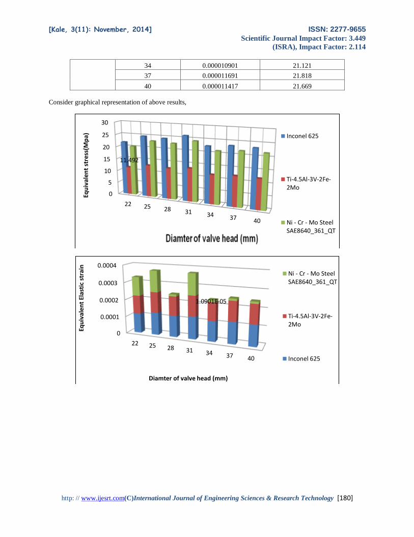
Table5: variation of Equivalent elastic stain and Equivalent stress with variation of diameter of valve head for material under
consideration.
Material
Diamter of valve
head(mm)
Equivalent Elastic
strain(mm/mm) Equivalent stress(Mpa)
Inconel 625
22 0.00011607 21.865
25 0.000131 24.794
28 0.00012379 24.441
31
0.00013111
26.085
34 0.00011723 22.697
37 0.00012573 23.446
40 0.00012278 23.285
Ti-4.5Al-3V-
2Fe-2Mo
22 0.00010658 11.492
25 0.00012019 13.019
28 0.00011221 12.632
31 0.00011888 13.46
34 0.00010643 11.775
37 0.00011463 12.23
40 0.00011156 12.115
Ni - Cr - Mo
Steel
SAE8640_36
1_QT
22 0.00010793 20.347
25 0.00012182 23.072
28 0.000011511 22.744
31 0.00012192 24.273
[Kale, 3(11): November, 2014] ISSN: 2277-9655
Scientific Journal Impact Factor: 3.449
(ISRA), Impact Factor: 2.114
http: // www.ijesrt.com(C)International Journal of Engineering Sciences & Research Technology [180]
34 0.000010901 21.121
37 0.000011691 21.818
40 0.000011417 21.669
Consider graphical representation of above results,
0
5
10
15
20
25
30
22 25 28 31 34 37 40
11.492
Equ
ival
ent
stre
ss(M
pa) Inconel 625
Ti-4.5Al-3V-2Fe-2Mo
Ni - Cr - Mo SteelSAE8640_361_QT
0
0.0001
0.0002
0.0003
0.0004
22 25 28 31 34 37 40
1.0901E-05
Equ
ival
ent
Elas
tic
stra
in
Diamter of valve head (mm)
Ni - Cr - Mo SteelSAE8640_361_QT
Ti-4.5Al-3V-2Fe-2Mo
Inconel 625
[Kale, 3(11): November, 2014] ISSN: 2277-9655
Scientific Journal Impact Factor: 3.449
(ISRA), Impact Factor: 2.114
http: // www.ijesrt.com(C)International Journal of Engineering Sciences & Research Technology [181]
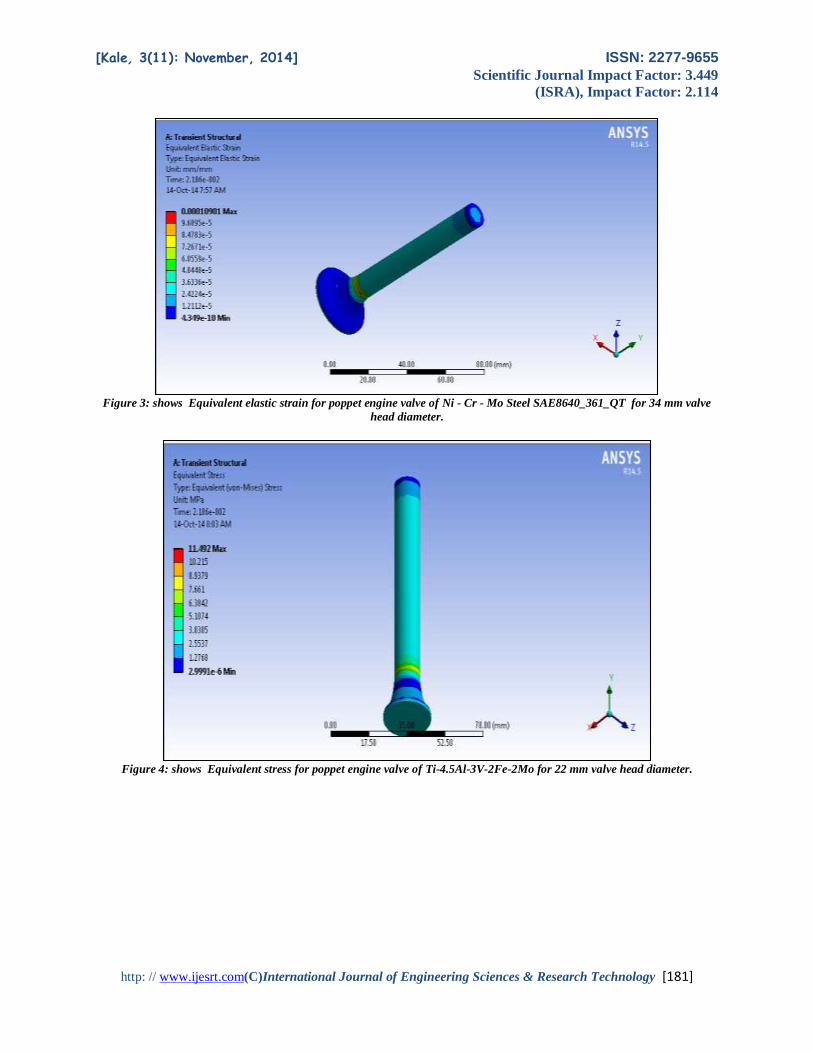
Figure 3: shows Equivalent elastic strain for poppet engine valve of Ni - Cr - Mo Steel SAE8640_361_QT for 34 mm valve
head diameter.
Figure 4: shows Equivalent stress for poppet engine valve of Ti-4.5Al-3V-2Fe-2Mo for 22 mm valve head diameter.
[Kale, 3(11): November, 2014] ISSN: 2277-9655
Scientific Journal Impact Factor: 3.449
(ISRA), Impact Factor: 2.114
http: // www.ijesrt.com(C)International Journal of Engineering Sciences & Research Technology [182]
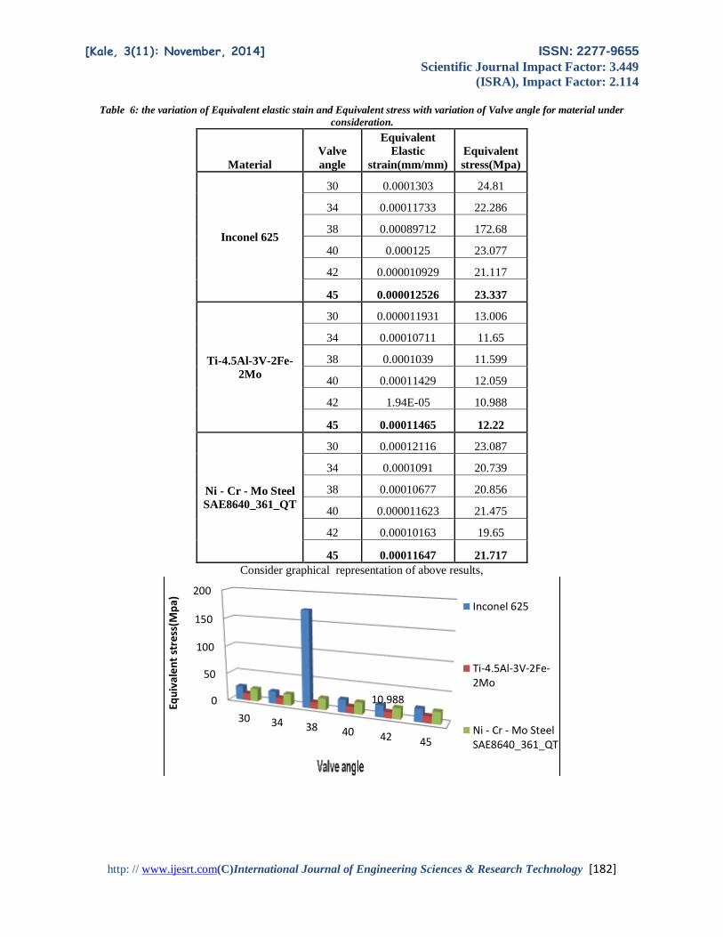
Table 6: the variation of Equivalent elastic stain and Equivalent stress with variation of Valve angle for material under
consideration.
Material
Valve
angle
Equivalent
Elastic
strain(mm/mm)
Equivalent
stress(Mpa)
Inconel 625
30 0.0001303 24.81
34 0.00011733 22.286
38 0.00089712 172.68
40 0.000125 23.077
42 0.000010929 21.117
45 0.000012526 23.337
Ti-4.5Al-3V-2Fe-
2Mo
30 0.000011931 13.006
34 0.00010711 11.65
38 0.0001039 11.599
40 0.00011429 12.059
42 1.94E-05 10.988
45 0.00011465 12.22
Ni - Cr - Mo Steel
SAE8640_361_QT
30 0.00012116 23.087
34 0.0001091 20.739
38 0.00010677 20.856
40 0.000011623 21.475
42 0.00010163 19.65
45 0.00011647 21.717
Consider graphical representation of above results,
0
50
100
150
200
30 34 38 40 42 45
10.988
Equ
ival
ent
stre
ss(M
pa) Inconel 625
Ti-4.5Al-3V-2Fe-2Mo
Ni - Cr - Mo SteelSAE8640_361_QT

[Kale, 3(11): November, 2014] ISSN: 2277-9655
Scientific Journal Impact Factor: 3.449
(ISRA), Impact Factor: 2.114
http: // www.ijesrt.com(C)International Journal of Engineering Sciences & Research Technology [183]
Figure 5: shows Equivalent elastic strain for poppet engine valve of Inconel 625 for 45 degree valve angle.
0
0.0002
0.0004
0.0006
0.0008
0.001
30 34 38 40 42 45
0.000012526Equ
ival
ent
Elas
tic
stra
in
Valve angle
Inconel 625
Ti-4.5Al-3V-2Fe-2Mo
Ni - Cr - MoSteelSAE8640_361_QT

[Kale, 3(11): November, 2014] ISSN: 2277-9655
Scientific Journal Impact Factor: 3.449
(ISRA), Impact Factor: 2.114
http: // www.ijesrt.com(C)International Journal of Engineering Sciences & Research Technology [184]
Figure 6: shows Equivalent stress for poppet engine valve of Ti-4.5Al-3V-2Fe-2Mo for 42 degree valve angle.
Table 7: illustrate the variation of Equivalent elastic stain and Equivalent stress with variation of Thickness of valve disk for
material under consideration.
Material
Thickness
of valve
disk(mm)
Equivalent
Elastic
strain(mm/m
m)
Equivalent
stress(Mpa)
Inconel 625
1 0.00010658 20.47
2 0.00012526 23.337
3 0.00011973 23.093
4 0.00011998 23.125
5 0.00012139 23.5
6 0.00011717 22.251
Ti-4.5Al-3V-
2Fe-2Mo
1 9.72E-05 10.689
2 0.00011465 12.22
3 0.00011097 11.933
4 0.00010844 11.981
5 1.10E-04 12.175
6 1.07E-04 11.619
Ni - Cr - Mo
Steel
SAE8640_361
_QT
1 9.91E-05 13.049
2 0.00011647 21.717
3 0.0001131 21.276
4 0.0001091 20.739
5 0.00011287 21.868
6 0.000010895 20.706
Consider graphical representation of above results,

[Kale, 3(11): November, 2014] ISSN: 2277-9655
Scientific Journal Impact Factor: 3.449
(ISRA), Impact Factor: 2.114
http: // www.ijesrt.com(C)International Journal of Engineering Sciences & Research Technology [185]
0
0.00002
0.00004
0.00006
0.00008
0.0001
0.00012
0.00014
1 2 3 4 5 6
0.000010895
Equ
ival
ent
Elas
tic
star
in
Thickness of valve disk(mm)
Inconel 625
Ti-4.5Al-3V-2Fe-2Mo
Ni - Cr - Mo SteelSAE8640_361_QT
0
5
10
15
20
25
1 2 3 4 5 6
10.689
Equ
ival
ent
stre
ss(M
pa)
Thickness of valve disk(mm)
Inconel 625
Ti-4.5Al-3V-2Fe-2Mo
Ni - Cr - Mo SteelSAE8640_361_QT

[Kale, 3(11): November, 2014] ISSN: 2277-9655
Scientific Journal Impact Factor: 3.449
(ISRA), Impact Factor: 2.114
http: // www.ijesrt.com(C)International Journal of Engineering Sciences & Research Technology [186]
Above figure shows Equivalent stress for poppet engine valve of Ni - Cr - Mo Steel SAE8640_361_QT for 6 mm valve disk
thickness.
Table 8: the variation of fatigue life with variation of geometric parameter and materials,
Material Fatigue life
Inconel 625 1.00E+06
Ti-4.5Al-3V-2Fe-2Mo 1.00E+07
Ni - Cr - Mo Steel
SAE8640_361_QT 1.00E+11
Above figure shows fatigue life of Ni - Cr - Mo Steel SAE8640_361_QT.
Conclusion
[Kale, 3(11): November, 2014] ISSN: 2277-9655
Scientific Journal Impact Factor: 3.449
(ISRA), Impact Factor: 2.114
http: // www.ijesrt.com(C)International Journal of Engineering Sciences & Research Technology [187]
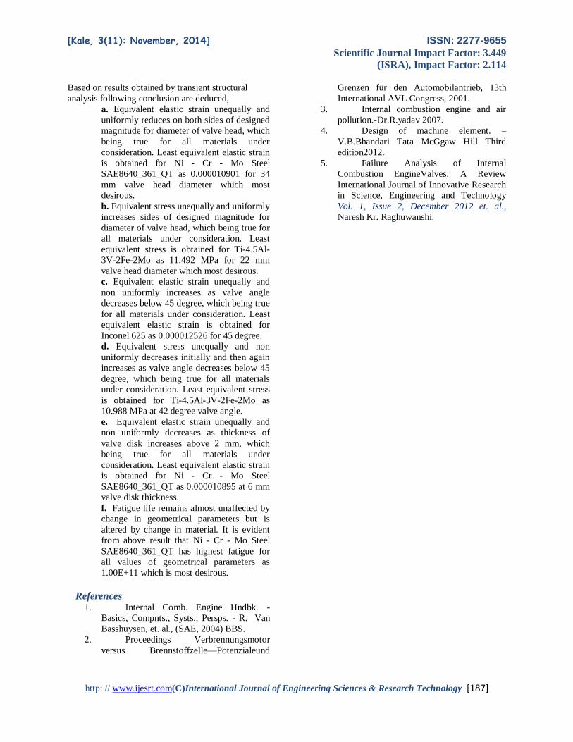
Based on results obtained by transient structural
analysis following conclusion are deduced,
a. Equivalent elastic strain unequally and
uniformly reduces on both sides of designed
magnitude for diameter of valve head, which
being true for all materials under
consideration. Least equivalent elastic strain
is obtained for Ni - Cr - Mo Steel
SAE8640_361_QT as 0.000010901 for 34
mm valve head diameter which most
desirous.
b. Equivalent stress unequally and uniformly
increases sides of designed magnitude for
diameter of valve head, which being true for
all materials under consideration. Least
equivalent stress is obtained for Ti-4.5Al-
3V-2Fe-2Mo as 11.492 MPa for 22 mm
valve head diameter which most desirous.
c. Equivalent elastic strain unequally and
non uniformly increases as valve angle
decreases below 45 degree, which being true
for all materials under consideration. Least
equivalent elastic strain is obtained for
Inconel 625 as 0.000012526 for 45 degree.
d. Equivalent stress unequally and non
uniformly decreases initially and then again
increases as valve angle decreases below 45
degree, which being true for all materials
under consideration. Least equivalent stress
is obtained for Ti-4.5Al-3V-2Fe-2Mo as
10.988 MPa at 42 degree valve angle.
e. Equivalent elastic strain unequally and
non uniformly decreases as thickness of
valve disk increases above 2 mm, which
being true for all materials under
consideration. Least equivalent elastic strain
is obtained for Ni - Cr - Mo Steel
SAE8640_361_QT as 0.000010895 at 6 mm
valve disk thickness.
f. Fatigue life remains almost unaffected by
change in geometrical parameters but is
altered by change in material. It is evident
from above result that Ni - Cr - Mo Steel
SAE8640_361_QT has highest fatigue for
all values of geometrical parameters as
1.00E+11 which is most desirous.
References 1. Internal Comb. Engine Hndbk. -
Basics, Compnts., Systs., Persps. - R. Van
Basshuysen, et. al., (SAE, 2004) BBS.
2. Proceedings Verbrennungsmotor
versus Brennstoffzelle—Potenzialeund
Grenzen für den Automobilantrieb, 13th
International AVL Congress, 2001.
3. Internal combustion engine and air
pollution.-Dr.R.yadav 2007.
4. Design of machine element. –
V.B.Bhandari Tata McGgaw Hill Third
edition2012.
5. Failure Analysis of Internal
Combustion EngineValves: A Review
International Journal of Innovative Research
in Science, Engineering and Technology
Vol. 1, Issue 2, December 2012 et. al.,
Naresh Kr. Raghuwanshi.