archived: gpib-pc user manual for the ibm personal ... · ibm personal computer and compatibles...
TRANSCRIPT

© Copyright 1984, 1994 National Instruments Corporation.All Rights Reserved.
GPIB-PC User Manualfor the
IBM Personal Computer andCompatibles
April 1988 Edition
Part Number 320014-01

National Instruments Corporate Headquarters6504 Bridge Point ParkwayAustin, TX 78730-5039(512) 794-0100Technical support fax: (800) 328-2203
(512) 794-5678
Branch Offices:Australia (03) 879 9422, Austria (0662) 435986, Belgium 02/757.00.20,Canada (Ontario) (519) 622-9310, Canada (Québec) (514) 694-8521,Denmark 45 76 26 00, Finland (90) 527 2321, France (1) 48 14 24 24,Germany 089/741 31 30, Italy 02/48301892, Japan (03) 3788-1921,Netherlands 03480-33466, Norway 32-848400, Spain (91) 640 0085,Sweden 08-730 49 70, Switzerland 056/20 51 51, U.K. 0635 523545

Limited Warranty
The GPIB-PC is warranted against defects in materials and workmanshipfor a period of two years from the date of shipment, as evidenced byreceipts or other documentation. National Instruments will, at its option,repair or replace equipment that proves to be defective during the warrantyperiod. This warranty includes parts and labor.
The media on which you receive National Instruments software arewarranted not to fail to execute programming instructions, due to defects inmaterials and workmanship, for a period of 90 days from date of shipment,as evidenced by receipts or other documentation. National Instruments will,at its option, repair or replace software media that do not executeprogramming instructions if National Instruments receives notice of suchdefects during the warranty period. National Instruments does not warrantthat the operation of the software shall be uninterrupted or error free.
A Return Material Authorization (RMA) number must be obtained from thefactory and clearly marked on the outside of the package before anyequipment will be accepted for warranty work. National Instruments willpay the shipping costs of returning to the owner parts which are covered bywarranty.
National Instruments believes that the information in this manual isaccurate. The document has been carefully reviewed for technicalaccuracy. In the event that technical or typographical errors exist, NationalInstruments reserves the right to make changes to subsequent editions ofthis document without prior notice to holders of this edition. The readershould consult National Instruments if errors are suspected. In no eventshall National Instruments be liable for any damages arising out of orrelated to this document or the information contained in it.
EXCEPT AS SPECIFIED HEREIN, NATIONAL INSTRUMENTS MAKES NOWARRANTIES, EXPRESS OR IMPLIED, AND SPECIFICALLY DISCLAIMSANY WARRANTY OF MERCHANTABILITY OR FITNESS FOR APARTICULAR PURPOSE. CUSTOMER'S RIGHT TO RECOVER DAMAGESCAUSED BY FAULT OR NEGLIGENCE ON THE PART OF NATIONALINSTRUMENTS SHALL BE LIMITED TO THE AMOUNT THERETOFOREPAID BY THE CUSTOMER. NATIONAL INSTRUMENTS WILL NOT BELIABLE FOR DAMAGES RESULTING FROM LOSS OF DATA, PROFITS,USE OF PRODUCTS, OR INCIDENTAL OR CONSEQUENTIAL DAMAGES,EVEN IF ADVISED OF THE POSSIBILITY THEREOF. This limitation of theliability of National Instruments will apply regardless of the form of action,whether in contract or tort, including negligence. Any action against

National Instruments must be brought within one year after the cause ofaction accrues. National Instruments shall not be liable for any delay inperformance due to causes beyond its reasonable control. The warrantyprovided herein does not cover damages, defects, malfunctions, or servicefailures caused by owner's failure to follow the National Instrumentsinstallation, operation, or maintenance instructions; owner's modification ofthe product; owner's abuse, misuse, or negligent acts; and power failure orsurges, fire, flood, accident, actions of third parties, or other events outsidereasonable control.
Copyright
Under the copyright laws, this publication may not be reproduced ortransmitted in any form, electronic or mechanical, including photocopying,recording, storing in an information retrieval system, or translating, inwhole or in part, without the prior written consent of National InstrumentsCorporation.
Trademarks
Product and company names listed are trademarks or trade names of theirrespective companies.
WARNING REGARDING MEDICAL ANDCLINICAL USE OF NATIONAL
INSTRUMENTS PRODUCTS
National Instruments products are not designed with components andtesting intended to ensure a level of reliability suitable for use in treatmentand diagnosis of humans. Applications of National Instruments productsinvolving medical or clinical treatment can create a potential for accidentalinjury caused by product failure, or by errors on the part of the user orapplication designer. Any use or application of National Instrumentsproducts for or involving medical or clinical treatment must be performedby properly trained and qualified medical personnel, and all traditionalmedical safeguards, equipment, and procedures that are appropriate in theparticular situation to prevent serious injury or death should alwayscontinue to be used when National Instruments products are being used.National Instruments products are NOT intended to be a substitute for anyform of established process, procedure, or equipment used to monitor orsafeguard human health and safety in medical or clinical treatment.

©National Instruments Corp. v GPIB-PC User Manual
Preface
Introduction to the GPIB
The GPIB is a link, or bus, or interface system, through whichinterconnected electronic devices communicate.
History of the GPIB
The original GPIB was designed by Hewlett-Packard (where it is calledthe HP-IB) to connect and control programmable instrumentsmanufactured by Hewlett-Packard. Because of its high data transferrates of from 250 kilobytes to 1 megabyte per second, the GPIB quicklygained popularity in other applications such as intercomputercommunication and peripheral control. It was later accepted as theindustry standard IEEE-488. The versatility of the system prompted thename General Purpose Interface Bus.
National Instruments expanded the use of the GPIB among users ofcomputers manufactured by companies other than Hewlett-Packard.National Instruments specialized both in high performance, high-speedhardware interfaces, and in comprehensive, full-function software thathelps users bridge the gap between their knowledge of instruments andcomputer peripherals and of the GPIB itself.
The GPIB-PC Family
The GPIB-PC family consists of GPIB interface hardware products,software, documentation, and other items for several types of personalcomputers.
What Your Package Should Contain
Unless you have a special application, your GPIB-PC package consistsof the following:
• A GPIB-PC interface board for your personal computer. Eachboard has a model name such as GPIB-PCIIA. This manual usesGPIB-PC to refer generally to all models of the GPIB-PCinterface board.
Preface
GPIB-PC User Manual vi ©National Instruments Corp.
• A Getting Started with your GPIB-PC pamphlet. The pamphletcontains the directions with a minimum of explanations forinstalling your hardware and software in your GPIB system.
• A GPIB-PC distribution diskette. The distribution diskette is partof the GPIB-PC package. It contains the DOS handler, BASICAand QuickBASIC language interfaces, and other programs.
• A GPIB-PC User Manual. The manual contains descriptions ofthe GPIB-PC handler functions, BASICA, and QuickBASIClanguage interfaces to the handler.
• A Programmer Reference Guide for BASIC.
• A supplement to Section Two of the manual describing yourparticular interface board and how to install it in your personalcomputer.
For a language other than BASICA and QuickBASIC, you also need:
• An additional GPIB-PC distribution diskette containing thesoftware for that language.
• A supplement to Section Four describing the GPIB functions inthe syntax and semantics of that language.
• A Programmer Reference Guide for that language.
Who Are Our Users?
Most of our users have experience in technological fields and withcomputers.
How to Get Started
If you already have experience with the GPIB, you may wish to turndirectly to the Getting Started with your GPIB-PC pamphlet that wasshipped with your hardware. It contains directions, with a minimum ofexplanations, for installing your hardware and software in your GPIBsystem.
If you are less experienced or want more information than the pamphletprovides, read this GPIB-PC User Manual. It explains in detail all of theinformation you will need for the proper operation of the GPIB-PC.
Preface
©National Instruments Corp. vii GPIB-PC User Manual
About the Manual
This manual is written specifically for a GPIB-PC which is to beinstalled in an IBM Personal Computer or compatible PC which isoperating under PC-DOS or MS-DOS and programmed using BASICAand QuickBASIC. With appropriate supplements to the manual, otherGPIB-PC interfaces can be installed in other computers, using otherprogramming languages.
Organization of the Manual
Section One - Operation of the GPIB describes the operation of theGPIB.
Section Two - Installation and Configuration describes the installation ofthe software and the configuration program IBCONF. A supplementcontains instructions for installing your particular board into yourcomputer.
Section Three - GPIB-PC Functions — Introduction introduces you to thefunctions used by your GPIB-PC. The features are divided into groupsas a means of helping you understand the uses of the functions.
Section Four - GPIB-PC Functions — Overview introduces you toprogramming information common to all languages.
Section Four A - Function Reference — Language Interface(s) pertains toBASICA and QuickBASIC. The descriptions are listed alphabeticallyfor easy reference.
Section Five - IBIC introduces you to IBIC, the interactive controlprogram that allows you to control and communicate with the GPIBthrough functions you enter at your keyboard. IBIC is designed to helpyou learn how to use the GPIB-PC functions to program your devices.
Section Six - Applications Monitor introduces you to the applicationsmonitor, a resident program that is useful in debugging sequences ofGPIB calls from within your application.
Appendix A - Multiline Interface Messages is a listing of MultilineInterface Command Messages.
Appendix B - Common Errors and Their Solutions singles out the mostcommon errors users have encountered and some probable solutions.

Preface
GPIB-PC User Manual viii ©National Instruments Corp.
Appendix C - Differences Between Software Revisions points outdifferences between revisions of the GPIB-PC handler.
Appendix D - Using your Printer with the GPIB-PC gives some quicksteps to connect your GPIB-PC with your printer.
Appendix E - Application Notes is an application note about computer-to-computer transfers.
Appendix F - Customer Communication contains forms you can use torequest help from National Instruments or to comment on our productsand manuals.
The Glossary contains an alphabetical list and description of terms usedin this manual, including abbreviations, acronyms, metric prefixes,mnemonics, and symbols.
The Index contains an alphabetical list of key terms and topics in thismanual, including the page where you can find each one.
Now, with your personal computer, your GPIB-PC, your manuals andsupplements, and these instructions, you are ready to get started withyour GPIB. We hope your experience will be a rewarding one.
Customer Support
National Instruments wants to receive your comments on our productsand manuals. We are interested in the applications you develop withour products, and we want to help if you have problems with them. Forinformation on how to contact us, refer to Appendix F, CustomerCommunication, at the end of this manual.

©National Instruments Corp. ix GPIB-PC User Manual
Contents
Section One - Operation of the GPIB ................................................ 1-1Types of Messages...................................................................................... 1-1Talkers, Listeners, and Controllers ..................................................... 1-1The Controller-In-Charge and System Controller......................... 1-2GPIB Signals and Lines........................................................................... 1-3
Data Lines..................................................................................... 1-3Handshake Lines........................................................................ 1-3
NRFD (not ready for data).................................. 1-3NDAC (not data accepted)................................. 1-4DAV (data valid)..................................................... 1-4
Interface Management Lines............................................... 1-4ATN (attention)........................................................ 1-4IFC (interface clear).............................................. 1-4REN (remote enable) ............................................ 1-4SRQ (service request)........................................... 1-5EOI (end or identify).............................................. 1-5
Physical and Electrical Characteristics............................................ 1-5Configuration Requirements................................................................... 1-9Related Documents .................................................................................... 1-9
Section Two - Installation and Configuration ............................ 2-1Installing the Hardware............................................................................. 2-1The GPIB-PC Software Package......................................................... 2-1
Additional Programs and Files............................................ 2-2Installing the Software .............................................................................. 2-3
Step 1 - Preparation.................................................................. 2-3Booting from a Floppy Disk............................... 2-3Booting from a Hard Disk.................................... 2-3
Step 2 - Run IBSTART........................................................... 2-4Step 3 - Run IBCONF (optional)....................................... 2-5Step 4 - Reboot........................................................................... 2-5Step 5 - Test Software Installation.................................... 2-5
More About IBCONF................................................................................. 2-6Characteristics of the Instruments ..................................... 2-7Characteristics of each GPIB-PC...................................... 2-7
Default Configurations .............................................................................. 2-8Primary Default Characteristics......................................... 2-8
Contents
GPIB-PC User Manual x ©National Instruments Corp.
Running IBCONF........................................................................................ 2-9Upper and Lower Levels of IBCONF............................ 2-10
Upper Level - Device Mapfor Board GPIBx.................................................... 2-10Device Map Concepts and Terms................ 2-11Lower Level - Device/BoardCharacteristics....................................................... 2-11
Device and Board Characteristics.................................. 2-12Primary GPIB Address....................................... 2-12Secondary GPIB Address.................................. 2-12Timeout Settings................................................... 2-12EOS Byte.................................................................. 2-14EOS Modes.............................................................. 2-14Set EOI with last byte of Write ..................... 2-14GPIB-PC Model .................................................... 2-14Board is System Controller(Boards Only)......................................................... 2-14Local Lockout on all Devices(Boards Only)......................................................... 2-15Disable Auto Serial Polling(Boards Only)......................................................... 2-15High-Speed Timing(Boards Only)......................................................... 2-15Interrupt Jumper Setting(Boards Only)......................................................... 2-15Base I/O Address (Boards Only)................... 2-15DMA Channel (Boards Only)......................... 2-16Internal Clock Frequency(Boards Only)......................................................... 2-16
Exiting IBCONF...................................................................... 2-16Using Your GPIB-PC.............................................................................. 2-18
Section Three - GPIB-PCFunctions — Introduction............................................................................ 3-1
Introduction to the GPIB-PC Functions............................................ 3-1High-Level Functions .............................................................. 3-1Low-Level Functions ............................................................... 3-1Calling Syntax............................................................................ 3-1
Group I .............................................................................................................. 3-2IBRD (bd,buf,cnt) ..................................................................... 3-2IBWRT (bd,buf,cnt)................................................................. 3-2IBFIND (bdname,bd)............................................................... 3-3
Contents
©National Instruments Corp. xi GPIB-PC User Manual
Group II............................................................................................................. 3-3IBRSP (bd,spr) ........................................................................... 3-3IBCLR (bd).................................................................................. 3-4
Clearing the Device VersusClearing the GPIB................................................... 3-4
Clearing the Device ............................. 3-4Clearing the GPIB................................. 3-4
IBTRG (bd).................................................................................. 3-4IBLOC (bd).................................................................................. 3-4
Placing a Device in Remote Mode................ 3-4Placing a Device in Local Mode..................... 3-5
Group III ........................................................................................................... 3-5IBRDA (bd,buf,cnt) and......................................................... 3-6IBRDF (bd,buf,cnt) and......................................................... 3-6IBWAIT (bd,mask)................................................................... 3-6IBSTOP (bd)................................................................................ 3-6IBTMO (bd,v) ............................................................................. 3-7IBONL (bd,v) .............................................................................. 3-7IBPCT (bd)................................................................................... 3-7
Group IV........................................................................................................... 3-8Purpose of Board Functions.................................................. 3-9Multiboard Capability............................................................. 3-9IBFIND (bdname,bd)............................................................ 3-10IBCMD (bd,buf,cnt) and..................................................... 3-10IBRD (bd,buf,cnt) and......................................................... 3-10IBWRT (bd,buf,cnt) and..................................................... 3-12IBSTOP (bd)............................................................................. 3-12IBWAIT (bd,mask)................................................................ 3-12IBTMO (bd,v) .......................................................................... 3-12IBONL (bd,v) ........................................................................... 3-12IBSIC (bd) ................................................................................. 3-12IBSRE (bd,v)............................................................................ 3-13IBGTS (bd,v)............................................................................ 3-13IBCAC (bd,v)........................................................................... 3-13IBRPP (bd,buf)........................................................................ 3-13IBPPC (bd,v)............................................................................ 3-13
More About Device and Board Functions .................................... 3-14Group V......................................................................................................... 3-15
IBRSV (bd,v) ........................................................................... 3-15IBLOC (bd)............................................................................... 3-15IBPPC (bd,v)............................................................................ 3-16IBIST (bd,v).............................................................................. 3-16IBWAIT (bd,mask)................................................................ 3-16
Contents
GPIB-PC User Manual xii ©National Instruments Corp.
Group VI........................................................................................................ 3-17IBEOT (bd,v)............................................................................ 3-17IBEOS (bd,v)............................................................................ 3-18IBBNA (bd,"GPIBn")........................................................... 3-18IBDMA (bd,v).......................................................................... 3-18IBPAD (bd,v) ........................................................................... 3-18IBSAD (bd,v) ........................................................................... 3-18IBRSC (bd,v) ........................................................................... 3-18IBTMO (bd,v) .......................................................................... 3-18
Section Four - GPIB-PCFunctions — Overview ................................................................................. 4-1
General Programming Information................................................... 4-1Status Word................................................................................................. 4-2Error Codes.................................................................................................. 4-6Count Variable......................................................................................... 4-11Read and Write Termination............................................................ 4-11Device Function Calls ......................................................................... 4-12Automatic Serial Polling.................................................................... 4-13
Section Four A - BASICA/QuickBASICGPIB-PC Function Calls ......................................................................... 4A-1
BASICA Files .......................................................................................... 4A-2QuickBASIC Files................................................................................. 4A-2
Programming Preparations for BASICA.................... 4A-3Programming Preparations for QuickBASIC........... 4A-4
BASICA/QuickBASIC GPIB-PC I/O Functions ...................... 4A-5BASICA/QuickBASIC "ON SRQ" Capability.......................... 4A-6New GPIB-PC Functions .................................................................. 4A-12GPIB-PC Function Descriptions.................................................... 4A-15
IBBNA......................................................................................................................... 4A-16IBCAC......................................................................................................................... 4A-17IBCLR.......................................................................................................................... 4A-19IBCMD........................................................................................................................ 4A-20IBCMDA..................................................................................................................... 4A-23IBDMA........................................................................................................................ 4A-25IBEOS.......................................................................................................................... 4A-26IBEOT.......................................................................................................................... 4A-30IBFIND........................................................................................................................ 4A-32IBGTS.......................................................................................................................... 4A-34IBIST............................................................................................................................ 4A-36IBLOC.......................................................................................................................... 4A-38IBONL.......................................................................................................................... 4A-40IBPAD.......................................................................................................................... 4A-42
Contents
©National Instruments Corp. xiii GPIB-PC User Manual
IBPCT.......................................................................................................................... 4A-44IBPPC.......................................................................................................................... 4A-45IBRD............................................................................................................................. 4A-47IBRDA ........................................................................................................................ 4A-50IBRDF.......................................................................................................................... 4A-54IBRDI........................................................................................................................... 4A-57IBRDIA........................................................................................................................ 4A-60IBRPP.......................................................................................................................... 4A-64IBRSC.......................................................................................................................... 4A-66IBRSP.......................................................................................................................... 4A-68IBRSV.......................................................................................................................... 4A-70IBSAD.......................................................................................................................... 4A-71IBSIC............................................................................................................................ 4A-73IBSRE.......................................................................................................................... 4A-74IBSTOP....................................................................................................................... 4A-76IBTMO......................................................................................................................... 4A-78IBTRAP....................................................................................................................... 4A-81IBTRG.......................................................................................................................... 4A-83IBWAIT....................................................................................................................... 4A-84IBWRT........................................................................................................................ 4A-87IBWRTA..................................................................................................................... 4A-90IBWRTF..................................................................................................................... 4A-93IBWRTI....................................................................................................................... 4A-95IBWRTIA .................................................................................................................. 4A-99
BASICA/QuickBASIC GPIBProgramming Examples................................................................... 4A-103
BASICA Example Program - Device...................... 4A-105BASICA Example Program - Board........................ 4A-108QuickBASIC Example Program - Device............. 4A-111QuickBASIC Example Program - Board ............... 4A-114
Section Five - IBIC .............................................................................................. 5-1Running IBIC................................................................................................. 5-2
Using HELP.................................................................................. 5-3Using IBFIND.............................................................................. 5-3Using IBWRT.............................................................................. 5-4Using IBRD.................................................................................. 5-4How to Exit IBIC....................................................................... 5-5Important Programming Note............................................... 5-5Using SET..................................................................................... 5-6
IBIC Functions and Syntax..................................................................... 5-7Other IBIC Functions and Syntax........................................................ 5-8Status Word................................................................................................. 5-10Error Code.................................................................................................... 5-11
Contents
GPIB-PC User Manual xiv ©National Instruments Corp.
Byte Count................................................................................................... 5-12Auxiliary Functions................................................................................. 5-12
SET (Select Device or Board)......................................... 5-13HELP (Display Help Information).................................. 5-13! (Repeat Previous Function)........................................... 5-14- (Turn OFF Display)............................................................ 5-14+ (Turn ON Display)............................................................. 5-15n* (Repeat Function n Times)......................................... 5-16$ (Execute Indirect File) .................................................... 5-17PRINT (Display the ASCII String)................................ 5-18E or Q (exit or quit)............................................................... 5-18
IBIC Sample Programs.......................................................................... 5-19Device Function Calls ......................................................... 5-19Board Function Calls............................................................ 5-22
Section Six - Applications Monitor ....................................................... 6-1Installing the Applications Monitor.................................................... 6-2
IBTRAP.......................................................................................... 6-2Applications Monitor Options................................................................ 6-5Main Commands.......................................................................................... 6-6Session Summary Screen........................................................................ 6-7Configuring the Trap Mask..................................................................... 6-7Configuring the Monitor Mode.............................................................. 6-7
Hiding and Showing the Monitor ....................................... 6-8
Appendix A - Multiline Interface Messages ................................. A-1Multiline Interface Messages................................................................ A-2Interface Message Reference List....................................................... A-4
Appendix B - Common Errorsand Their Solutions............................................................................................. B-1
EDVR(0).......................................................................................................... B-1ECIC(1)............................................................................................................ B-1ENOL(2).......................................................................................................... B-2EADR(3).......................................................................................................... B-3EARG(4).......................................................................................................... B-3ESAC(5).......................................................................................................... B-4EABO(6).......................................................................................................... B-4ENEB(7).......................................................................................................... B-5EOIP(10).......................................................................................................... B-5ECAP(11)........................................................................................................ B-5EFSO(12)........................................................................................................ B-5EBUS(14)........................................................................................................ B-6ESTB(15)........................................................................................................ B-6
Contents
©National Instruments Corp. xv GPIB-PC User Manual
ESRQ(16)........................................................................................................ B-6Other Error Conditions............................................................................... B-7
Appendix C - Differences BetweenSoftware Revisions............................................................................................... C-1
Revision B and Revision C.................................................................... C-1Interrupts ........................................................................................ C-1Startup Program.......................................................................... C-1Configuration Program............................................................ C-1Interface Bus Interactive Control Program (IBIC) .... C-1New Functions............................................................................ C-2Modified Functions................................................................... C-2Language Interfaces ................................................................. C-2General ........................................................................................... C-2
Revision C and Revision D.................................................................... C-2Device Functions....................................................................... C-2Non-Interrupt Mode................................................................... C-2Asynchronous I/O....................................................................... C-3DMA on the GPIB-PCIII ........................................................ C-3Local Lockout ............................................................................. C-3SRQI Status Bit.......................................................................... C-3ATN and/or TIMO..................................................................... C-3DCAS and DTAS Status Bits .............................................. C-3Printer Support ............................................................................ C-3
Appendix D - Using your Printerwith the GPIB-PC ............................................................................................... D-1
Installation...................................................................................................... D-1
Appendix E - Application Notes.............................................................. E-1Application Note 1 - Computer to ComputerData Transfer ................................................................................................. E-1
Step 1. Configure the Computers...................................... E-1Step 2. Establish Communication.................................... E-1Step 3. Transfer Data.............................................................. E-2
Appendix F - Customer Communication ....................................... F-1
Glossary......................................................................................................................... G-1
Index................................................................................................................................. I-1
©National Instruments Corp. xvii GPIB-PC User Manual
Illustrations
List of Figures
Figure 1.1 - GPIB Connector and the Signal Assignment .........................1-6Figure 1.2 - Linear Configuration ..........................................................................1-7Figure 1.3 - Star Configuration ...............................................................................1-8
Figure 3.1 - Multiboard GPIB System...............................................................3-11
Figure 6.1 - Applications Monitor Popup Screen...........................................6-1
List of Tables
Table 2.1 - Timeout Settings................................................................................. 2-13Table 2.2 - Functions that Alter Default Characteristics .........................2-17
Table 4.1 - Status Word Layout.............................................................................4-2Table 4.2 - GPIB Error Codes..................................................................................4-6
Table 4A.1 - BASICA GPIB-PC Functions ..................................................4A-7Table 4A.2 - QuickBASIC GPIB-PC Calls...................................................4A-8Table 4A.3 - QuickBASIC GPIB-PC Calls.................................................4A-10Table 4A.4 - QuickBASIC Version 4.0 GPIB-PC Functions..............4A-14
Table 5.1 - Syntax of GPIB Functions in IBIC...............................................5-8Table 5.2 - Status Word Layout........................................................................... 5-11Table 5.3 - Auxiliary Functions that IBIC Supports ...................................5-12
©National Instruments Corp. 1-1 GPIB-PC User Manual
Section One - Operation of the GPIB
Communication between interconnected devices is achieved by passingmessages through the interface system.
Types of Messages
The GPIB carries two types of messages — device-dependent messagesand interface messages.
• Device-dependent messages, often called data or data messages,contain device-specific information such as programminginstructions, measurement results, machine status, and data files.
• Interface messages manage the bus itself. They are usuallycalled commands or command messages. Interface messagesperform such functions as initializing the bus, addressing andunaddressing devices, and setting device modes for remote orlocal programming.
The term command as used here should not be confused with somedevice instructions which can also be called commands. Such device-specific instructions are actually data messages.
Talkers, Listeners, and Controllers
A Talker sends data messages to one or more Listeners. The Controllermanages the flow of information on the GPIB by sending commands toall devices.
Devices can be Listeners, Talkers, and/or Controllers. A digitalvoltmeter, for example, is a Talker and may be a Listener as well.
The GPIB is a bus like an ordinary computer bus except that thecomputer has its circuit cards interconnected via a backplane buswhereas the GPIB has standalone devices interconnected via a cablebus.
The role of the GPIB Controller can also be compared to the role of thecomputer's CPU, but a better analogy is to the switching center of a citytelephone system.

Operation of the GPIB Section One
GPIB-PC User Manual 1-2 ©National Instruments Corp.
The switching center (Controller) monitors the communications network(GPIB). When the Controller notices that a party (device) wants tomake a call (send a data message), it connects the caller (Talker) tothe receiver (Listener).
The Controller usually addresses a Talker and a Listener before theTalker can send its message to the Listener. After the message istransmitted, the Controller usually unaddresses both devices.
Some bus configurations do not require a Controller. For example, onedevice may always be a Talker (called a Talk-only device) and theremay be one or more Listen-only devices.
A Controller is necessary when the active or addressed Talker orListener must be changed. The Controller function is usually handled bya computer.
With the GPIB-PC interface board and its software, your personalcomputer plays all three roles:
• Controller - to manage the GPIB,
• Talker - to send data, and
• Listener - to receive data.
The Controller-In-Charge and System Controller
Although there can be multiple Controllers on the GPIB, only oneController at a time is active, or Controller-In-Charge (CIC). Activecontrol can be passed from the current CIC to an idle Controller. Onlyone device on the bus, the System Controller, can make itself the CIC.The GPIB-PC is usually the System Controller.
Section One Operation of the GPIB
©National Instruments Corp. 1-3 GPIB-PC User Manual
GPIB Signals and Lines
The interface system consists of 16 signal lines and 8 ground return orshield drain lines.
The 16 signal lines are divided into the following three groups:
• 8 data lines,
• 3 handshake lines, and
• 5 interface management lines.
Data Lines
The eight data lines, DIO1 through DIO8, carry both data and commandmessages. All commands and most data use the 7-bit ASCII or ISOcode set, in which case the 8th bit, DIO8, is unused or used for parity.
Handshake Lines
Three lines asynchronously control the transfer of message bytesbetween devices:
• NRFD,
• NDAC, and
• DAV.
The process is called a three-wire interlocked handshake and itguarantees that message bytes on the data lines are sent and receivedwithout transmission error.
NRFD (not ready for data)
NRFD indicates when a device is ready or not ready to receive amessage byte. The line is driven by all devices when receivingcommands and by Listeners when receiving data messages.

Operation of the GPIB Section One
GPIB-PC User Manual 1-4 ©National Instruments Corp.
NDAC (not data accepted)
NDAC indicates when a device has or has not accepted a message byte.The line is driven by all devices when receiving commands and byListeners when receiving data messages.
DAV (data valid)
DAV tells when the signals on the data lines are stable (valid) and canbe accepted safely by devices. The Controller drives DAV lines whensending commands and the Talker drives DAV lines when sending datamessages.
Interface Management Lines
Five lines are used to manage the flow of information across theinterface:
• ATN,
• IFC,
• REN,
• SRQ, and
• EOI.
ATN (attention)
The Controller drives ATN true when it uses the data lines to sendcommands and false when it allows a Talker to send data messages.
IFC (interface clear)
The System Controller drives the IFC line to initialize the bus andbecome CIC.
REN (remote enable)
The System Controller drives the REN line, which is used to placedevices in remote or local program mode.

Section One Operation of the GPIB
©National Instruments Corp. 1-5 GPIB-PC User Manual
SRQ (service request)
Any device can drive the SRQ line to asynchronously request servicefrom the Controller.
EOI (end or identify)
The EOI line has two purposes. The Talker uses the EOI line to markthe end of a message string. The Controller uses the EOI line to telldevices to identify their response in a parallel poll.
Physical and Electrical Characteristics
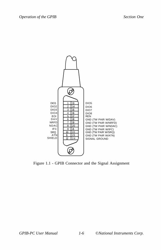
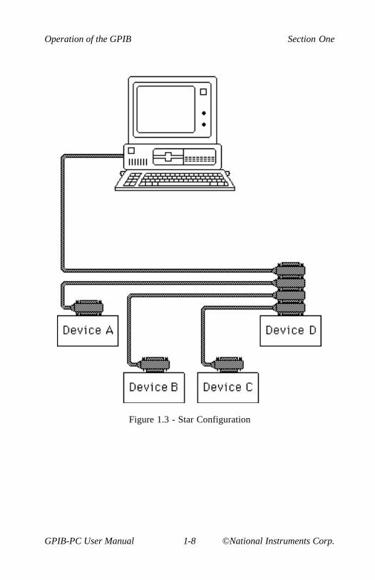
Devices are usually connected with a cable assembly consisting of ashielded 24-conductor cable with both a plug and receptacle connectorat each end. This design allows devices to be linked in either a linearor a star configuration, or a combination of the two. See Figures 1.1,1.2, and 1.3.
The standard connector is the Amphenol or Cinch Series 57MICRORIBBON or AMP CHAMP type. An adapter cable using non-standard cable and/or connector is used for special interconnectapplications.
The GPIB uses negative logic with standard TTL logic level. WhenDAV is true, for example, it is a TTL low-level ( ≤ 0.8V), and whenDAV is false, it is a TTL high-level ( ≥ 2.0V).
Operation of the GPIB Section One
GPIB-PC User Manual 1-6 ©National Instruments Corp.
123456789
101112
131415161718192021222324
DIO5DIO6DIO7DIO8RENGND (TW PAIR W/DAV)GND (TW PAIR W/NRFD)GND (TW PAIR W/NDAC)GND (TW PAIR W/IFC)GND (TW PAIR W/SRQ)GND (TW PAIR W/ATN)SIGNAL GROUND
DIO1DIO2DIO3DIO4EOI
DAVNRFDNDAC
IFCSRQATN
SHIELD
Figure 1.1 - GPIB Connector and the Signal Assignment

Section One Operation of the GPIB
©National Instruments Corp. 1-7 GPIB-PC User Manual
Figure 1.2 - Linear Configuration
Operation of the GPIB Section One
GPIB-PC User Manual 1-8 ©National Instruments Corp.
Figure 1.3 - Star Configuration
Section One Operation of the GPIB
©National Instruments Corp. 1-9 GPIB-PC User Manual
Configuration Requirements
To achieve the high data transfer rate that the GPIB was designed for,the physical distance between devices and the number of devices on thebus are limited.
The following restrictions are typical.
• A maximum separation of four meters between any two devicesand an average separation of two meters over the entire bus.
• A maximum total cable length of 20 meters.
• No more than 15 devices connected to each bus, with at leasttwo-thirds powered on.
Bus extenders are available from National Instruments and othermanufacturers for use when these limits must be exceeded.
Related Documents
For more information on topics covered in this section consult thefollowing related documents.
• IEEE Std. 488-1978, IEEE Standard Digital Interface forProgrammable Instrumentation.
• GPIB-PC Technical Reference Manual.

©National Instruments Corp. 2-1 GPIB-PC User Manual
Section Two - Installation andConfiguration
The procedures for installing your GPIB-PC depend on your model ofboard and your make of computer. A supplement to Section Twocontains information about your interface board. Section Two A, forexample, contains information about the model GPIB-PCIIA for the IBMPC and compatible computers.
Installing the Hardware
To install your hardware, follow the instructions in the Section Twosupplement for your interface board.
If you change the default settings of any switches, make a note of thenew values so that you can refer to them when you configure yoursoftware.
Install the hardware before continuing.
The GPIB-PC Software Package
Before you install your software, you might wish to review the files onyour GPIB-PC distribution diskette to gain an understanding of whatthey are.
The following files are the main files of the GPIB-PC software:
• GPIB.COM - is a device handler file that is loaded at systemstart-up by the DOS operating system. Handler is a term usedby National Instruments to refer to a loadable device driver.
• BIB.M - is a language interface file that provides anapplication program access to the GPIB-PC handler. BIB.M isintended for use with programs written in BASICA.
• QBIB*.OBJ - is a language interface file that provides anapplication program access to the GPIB-PC handler.QBIB*.OBJ is intended for use with programs written inQuickBASIC.

Installation and Configuration Section Two
GPIB-PC User Manual 2-2 ©National Instruments Corp.
• DECL.BAS - is a declaration file that contains code to beplaced at the beginning of the BASICA and QuickBASICapplication programs.
• QBDECL.BAS - is a declaration file that contains code to beplaced at the beginning of the QuickBASIC applicationprograms.
Additional Programs and Files
The following additional programs and files include installation, test,and example programs:
• APPMON.COM - is the applications monitor program. It is aresident program that is useful in debugging sequences of GPIBcalls from within your application. The applications monitorprovides the capability to trap on return from GPIB driver calls,allowing you to inspect function arguments, buffers, returnvalues, GPIB global variables, and other pertinent data.
• IBTRAP.EXE - is a program that configures the applicationsmonitor.
• IBSTART.BAT - is a batch file used for installation and start-up. It is a multipurpose program that performs the softwareinstallation. It copies files, modifies CONFIG.SYS (the DOSsystem configuration file) using MKCFG.EXE, and tests thehardware using IBDIAG.EXE.
• IBDIAG.EXE - is a program that tests the hardware installationbefore the GPIB software is configured and installed. After thehandler is installed, IBTEST.BAT confirms that both thesoftware and hardware are installed and functioning properly.The test is executed in two parts using IBTSTA.EXE andIBTSTB.EXE.
• IBCONF.EXE - is a software configuration program that allowsyou to change the software parameters and other data used bythe handler.
• IBIC.EXE - is an interactive control program that allows youto execute the handler functions interactively from yourkeyboard. It helps you to learn the functions, to program yourinstrument or other GPIB device, and to develop yourapplication program.

Section Two Installation and Configuration
©National Instruments Corp. 2-3 GPIB-PC User Manual
• DBSAMP.BAS, BBSAMP.BAS, DQBSAMP, BIBSAMP, andDIBSAMP - are example programs for BASICA, QuickBASIC,and IBIC. The BASICA and QuickBASIC supplement of themanual, Section Four A, contains additional examples.
Installing the Software
The term boot disk refers to the hard disk or floppy disk that containsDOS and that is read by your computer when it is booted. The termboot refers to the action of loading DOS into your system from your bootdisk, either when power is applied or when the warm boot keys arepressed.
Step 1 - Preparation
Your first step is determined by whether you wish to boot from a floppydisk or a hard disk. Perform the step that applies to your system.
Booting from a Floppy Disk
If you boot DOS from a floppy diskette, you need a boot disk withenough free space to hold a copy of the GPIB-PC software contained onthe distribution diskette.
Insert the boot diskette into the first drive (usually named A:) and thedistribution diskette into the second drive (B:). Boot your system if youhave not already done so.
Booting from a Hard Disk
If you boot DOS from a hard disk, you need a personal computer withone floppy drive. The hard disk must have enough free space to hold acopy of the GPIB-PC software contained on the distribution diskette.
Boot your system. Then, insert the distribution diskette into the floppydrive.

Installation and Configuration Section Two
GPIB-PC User Manual 2-4 ©National Instruments Corp.
Step 2 - Run IBSTART
Run IBSTART from the distribution diskette by switching to the drivecontaining the distribution diskette and entering:
ibstart x:
replacing x with the letter of the boot drive. For example, if thedistribution diskette is in drive B and you have booted from drive A,enter:
b:
to switch to drive B. Next, enter:
ibstart a:
to run IBSTART.
IBSTART first creates a directory called GPIB-PC on the boot diskette,and copies the GPIB software to that directory. If the insufficientdisk space message appears, abort the IBSTART program bypressing the control key while you enter:
c
Increase the free space in your boot area and run IBSTART again.
Next, IBSTART creates or modifies the DOS system configuration fileCONFIG.SYS to contain the line:
DEVICE=GPIB.COM
By reading this file at boot time, DOS installs new device drivers andhandlers.
Next, IBSTART switches to the boot drive to run the hardwarediagnostic program, IBDIAG.
Section Two Installation and Configuration
©National Instruments Corp. 2-5 GPIB-PC User Manual
Finally, IBSTART advises you to complete the following actions:
• Run IBCONF if you must reconfigure the software;
• Reboot your system to load the handler into DOS; and
• Run IBTEST to test the installation of the software.
Step 3 - Run IBCONF (optional)
The pamphlet Getting Started with your GPIB-PC that comes with yourinterface board explains when you must run IBCONF to reconfigure thesoftware. You may also run IBCONF to examine how the software isconfigured.
See More About IBCONF later in this section for information on how torun IBCONF and on the configurable software parameters.
NOTE: You must run IBCONF if you have a PCIIA, or wish to changedefaults.
Step 4 - Reboot
Reboot your computer from the drive you specified when you ranIBSTART so that DOS will load the GPIB-PC handler.
Step 5 - Test Software Installation
Run IBTEST from the directory GPIB-PC in your boot area by entering:
cd gpib-pcibtest
IBTEST tests whether the handler is installed and functioning with theGPIB-PC.

Installation and Configuration Section Two
GPIB-PC User Manual 2-6 ©National Instruments Corp.
If errors occur, check the following:
• Did you read Getting Started with your GPIB-PC and make anyrequired changes? If not, do so now.
• Did you change hardware switch settings on your GPIB-PCboard? If so, run IBCONF and accurately input the new settingsfor the board.
• Are the GPIB.COM and CONFIG.SYS files installed in the rootdirectory of your boot drive? If not, check and repeat theinstallation instructions.
• Did you reboot your system before you ran IBTEST? If not, doso now.
If you have performed these steps and IBTEST still fails, carefully noteall error information and call National Instruments.
If no errors occur, proceed to the end of this section to learn how to usethe software and to develop your application program.
More About IBCONF
IBCONF is a screen-oriented, interactive program that is included on thedistribution diskette of the GPIB-PC package.
You use IBCONF to edit the description in the handler of characteristicsof the devices and boards in the system. Running IBCONF to place thisinformation directly in the handler eliminates the need to restate itinside each application program.
IBCONF passes two groups of features to the handler. The first groupconsists of the characteristics of the instruments or devices attached toyour GPIB-PC. The second group consists of the characteristics of eachGPIB-PC installed in the computer.
Section Two Installation and Configuration
©National Instruments Corp. 2-7 GPIB-PC User Manual
Characteristics of the Instruments
Each instrument used with the GPIB-PC has the followingcharacteristics:
• A symbolic name of each device on the GPIB (such as DEV5 orPS5010).
• A GPIB-PC access board for each device (e.g., GPIB0). Theaccess board is discussed in Device Map Concepts and Termslater in this section.
• A primary and, if used, secondary address for each device.
• A time limit that is to be imposed when executing certainfunctions. This is to ensure that accessing a powered-off devicedoes not hang up the GPIB indefinitely.
• A way to terminate I/O transmissions to and from the device.Some devices require or append an end-of-string character, suchas the ASCII line feed character, to data strings. Others use theGPIB END message, which is sent or received via the EOIsignal line. Still others use both. Some terminate messagesonly when a predetermined number of bytes are sent orreceived.
Characteristics of each GPIB-PC
Each GPIB-PC has the following characteristics:
• A symbolic name (such as GPIB0 and GPIB1).
• A computer I/O or port address.
• The capability to be designated as the System Controller of thedevices on its bus.
• A time limit that is imposed when executing certain functions.
• A way to terminate I/O transmissions to and from the boardwhen executing board calls, i.e., by an end-of-string character,an END message, and/or a byte count.
• An interrupt level that the board uses.
Installation and Configuration Section Two
GPIB-PC User Manual 2-8 ©National Instruments Corp.
• What DMA channel, if any, the board uses.
• Whether it uses high-speed or normal timing when transmittingdata to a device. With normal timing, there is a delay of atleast 2 µsec after the data is placed on the GPIB before theData Valid (DAV) line is asserted. With high-speed timing,this delay is decreased to about 500 nsec.
• The Internal Clock Frequency for a PC-IIA. This is the value ofthe internal PC bus clock.
Default Configurations
Just as the hardware has factory default settings for switches andjumpers, the software also has factory default configurations. Forexample, the default device names of the 16 GPIB devices are DEV1through DEV16, but you might wish to assign more descriptive names toeach device, such as METER for a digital multimeter.
You can also use IBCONF to look at the current default settings in thehandler file.
If you do not make changes using IBCONF, the default characteristics ofthe software remain in effect.
Primary Default Characteristics
The following are the primary default characteristics of the handler.
• There are 16 active devices with symbolic names DEV1 throughDEV16.
• GPIB addresses of these devices are the same as the devicenumber; for example, DEV1 is at address 1.
• The 16 devices are assigned to GPIB0 as their access board.GPIB0 is the symbolic name of the first GPIB-PC board in yoursystem. If you have an additional GPIB-PC in your system, itssymbolic name is GPIB1.
• Each GPIB-PC is System Controller of its independent bus andhas a GPIB address of 0.
• The END message is sent with the last byte of each datamessage to a device. Each data message that is read from a

Section Two Installation and Configuration
©National Instruments Corp. 2-9 GPIB-PC User Manual
device is automatically terminated when END is received. Noend-of-string character is recognized.
• The time limit on I/O and wait function calls is approximately10 seconds.
• GPIB0 is a Model GPIB-PCII, is at base I/O address hex 02B8,and uses DMA Channel 1 and TLC Interrupt Line 7.
• You must run IBCONF if you are using a GPIB-PCIIA or if youhave changed the hardware switches/jumpers on any GPIB-PCfrom the factory settings. Otherwise, it is unnecessary to runIBCONF. Consult the appropriate supplement to Section Twoof the user manual to find the factory settings of your GPIB-PCmodel.
Running IBCONF
When you ran IBSTART, a copy of IBCONF.EXE was placed on yourboot drive.
To run IBCONF, go to the root directory of the boot drive and enter:
ibconf
If you have a color monitor, the configuration program willautomatically appear in color. If you have a color monitor but want theconfiguration program to appear in monochrome, enter:
ibconf -m
IBCONF scans the handler file, GPIB.COM, and reads its data structuresinto memory. After you press a key, the program displays the DeviceMap for board GPIB0.
Installation and Configuration Section Two
GPIB-PC User Manual 2-10 ©National Instruments Corp.
IBCONF makes changes to the GPIB.COM file, which should also be inthe root directory. If you want IBCONF to make changes to a differentcopy of GPIB.COM such as GPIB2.COM, enter the path and name ofthe GPIB.COM file you want modified:
ibconf c:\GPIB-PC\GPIB2.COM
This will have the effect of changing the parameters within theGPIB2.COM file in the GPIB-PC subdirectory.
Modify only the copy of GPIB.COM created by IBSTART in your bootdirectory. Never modify the master copy on the distribution diskette.This would happen if you ran IBCONF from the distribution diskette andif the distribution diskette were not write-protected.
Upper and Lower Levels of IBCONF
IBCONF operates at both an upper and a lower level. The upper levelconsists of the Device Maps and gives an overview of the GPIB systemas defined within the handler being configured. The lower level consistsof screens that describe each individual board and device in the system.
Upper Level - Device Map for Board GPIBx
This screen displays the names of all devices defined in the handler file,and indicates which devices, if any, are accessed through the interfaceboard GPIBx. At this level, you may:
• Rename a device;
• Disconnect a device from its assigned GPIB-PC access board orconnect (reassign) it to a different access board; or
• Proceed to the lower level to edit or examine thecharacteristics of a particular board or device.
Instructions are given on the screen for selecting the individual devicesand for changing from one device map to another, for example, from themap for GPIB0 to that for GPIB1.

Section Two Installation and Configuration
©National Instruments Corp. 2-11 GPIB-PC User Manual
Device Map Concepts and Terms
• Device Name - contains up to seven characters. The rules fornaming devices are the same as DOS rules for naming files,except that suffixes (.xxx) are not allowed. DOS treatsuppercase and lowercase letters identically. The string"PLOTTER" is treated the same as the string "plotter". Forthis reason, the configuration program maps all lowercaseletters to uppercase.
Device names must not be given the same names as files,directories, and/or subdirectories. If you name a device PLTRand your file system already contains the file PLTR.DAT or asubdirectory PLTR, a conflict results.
• Access Board - all devices on the GPIB require an access boardwithin the computer. The access board is the GPIB-PCinterface board that provides the hardware link to the computer.The access board name is of the form GPIBx, where x is adigit 0 or 1 representing the appropriate GPIB board number.The access board name is not alterable.
The string representing a device or board name is the firstvariable argument of the function IBFIND called at thebeginning of your application program. Refer to Sections Threeand Four for detailed explanations of IBFIND.
Lower Level - Device/Board Characteristics
The lower level screens display the currently defined values forcharacteristics such as addressing and timeout information of a deviceor board. Instructions are available on the screen for selecting a specificfield and for modifying the current settings. The configuration settingsselected for each device and each board are a means of customizing thecommunications and other options to be used with that board or device.
The settings for devices specify the characteristics to be used by theaccess board for that device when device functions are used.
The settings for boards specify the characteristics to be used with eachboard when board functions are used. In the following explanations ofdevice and board characteristics, notice that some characteristics applyto both devices and boards and some apply only to boards.

Installation and Configuration Section Two
GPIB-PC User Manual 2-12 ©National Instruments Corp.
Device and Board Characteristics
Primary GPIB Address
Each device and board must be assigned a unique primary address in therange hex 00 to hex 1E. A listen address is formed by adding hex 20 tothe primary address; the talk address is formed by adding hex 40 to theprimary address. Consequently, a primary address of hex 10 correspondsto a listen address of hex 30 and a talk address of hex 50. The GPIBprimary address of any device is set within that device, either withhardware switches, or, in some cases, a software program. This addressand the address listed in IBCONF must be the same. Refer to thedevice-specific documentation provided with your instrument forinstructions about that device's address. The primary GPIB address ofall GPIB-PC boards is 0, unless changed by IBCONF. There are nohardware switches on the GPIB-PC to select the GPIB address.
Secondary GPIB Address
Any device or board using extended addressing must be assigned asecondary address in the range hex 60 to hex 7E, or the option NONEmay be selected to disable secondary addressing. As with primaryaddressing, the secondary GPIB address of any device is set within thatdevice, either with hardware switches, or, in some cases, a softwareprogram. This address and the address listed in IBCONF must be thesame. Refer to the device documentation for instructions. Secondaryaddressing is disabled for all devices and boards unless changed byIBCONF.
Timeout Settings
The timeout value is the approximate length of time that may elapsebefore I/O functions such as IBRD, IBWRT, and IBCMD complete. It isalso the length of time that the IBWAIT function waits for an eventbefore returning if the TIMO bit is set. Consequently, a wait for theSRQ line to be asserted will terminate after the time limit is reached ifboth the SRQI and TIMO bits are set in the mask passed to IBWAIT,and no SRQ signal is detected. Refer to the IBWAIT functiondescription in Sections Three and Four for more information.
Section Two Installation and Configuration
©National Instruments Corp. 2-13 GPIB-PC User Manual
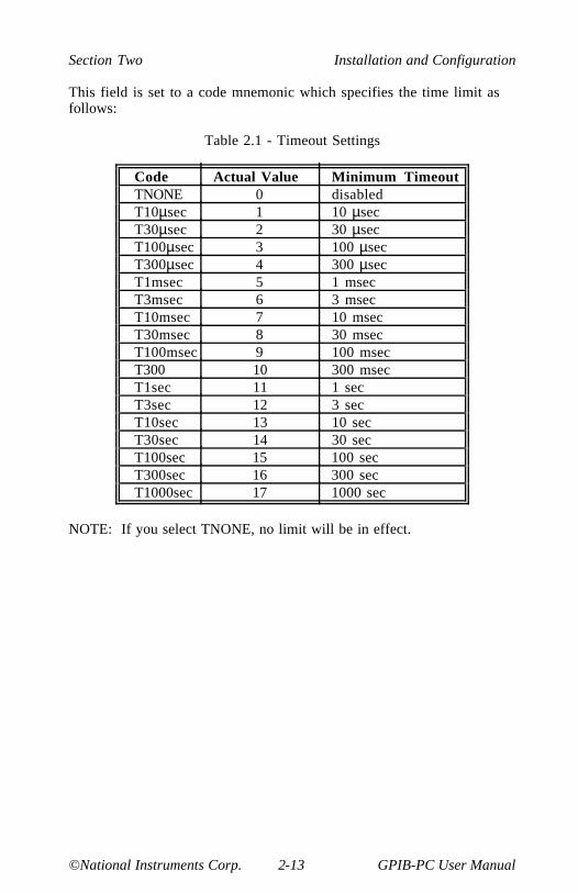
This field is set to a code mnemonic which specifies the time limit asfollows:
Table 2.1 - Timeout Settings
Code Actual Value Minimum TimeoutTNONE 0 disabledT10µsec 1 10 µsecT30µsec 2 30 µsecT100µsec 3 100 µsecT300µsec 4 300 µsecT1msec 5 1 msecT3msec 6 3 msecT10msec 7 10 msecT30msec 8 30 msecT100msec 9 100 msecT300 10 300 msecT1sec 11 1 secT3sec 12 3 secT10sec 13 10 secT30sec 14 30 secT100sec 15 100 secT300sec 16 300 secT1000sec 17 1000 sec
NOTE: If you select TNONE, no limit will be in effect.

Installation and Configuration Section Two
GPIB-PC User Manual 2-14 ©National Instruments Corp.
EOS Byte
Some devices can be programmed to terminate a read operation when aselected character is detected. A linefeed character (hex 0A) is apopular one.
NOTE: To send the EOS character to a device in a write operation, youmust explicitly include that byte in your data string.
EOS Modes
• Terminate a Read on EOS - Some devices send an EOS bytesignaling the last byte of a data message. A yes response willcause the GPIB-PC to terminate read operations when itreceives the EOS byte.
• Set EOI with EOS on Write - A yes response will cause theGPIB-PC to assert the EOI (send END) line when the EOScharacter is sent.
• 7- or 8-bit compare on EOS - Along with the designation of anEOS character, you may specify whether all eight bits arecompared to detect EOS, or just the seven least significant bits(ASCII or ISO format).
Set EOI with last byte of Write
Some devices, as Listeners, require that the Talker terminate a datamessage by asserting the EOI signal line (sending END) with the lastbyte. A yes response will cause the GPIB-PC to assert EOI on the lastdata byte.
GPIB-PC Model
The GPIB-PC Model must be specified so that the handler will use theappropriate hardware addressing scheme.
Board is System Controller (Boards Only)
This field appears on the board characteristics screen only. Generally,the GPIB-PC will be the System Controller. In some situations, such asin a network of computers linked by the GPIB, another device may beSystem Controller and the GPIB-PC will NOT be designated SystemController. A yes response designates the GPIB-PC to be SystemController. A no response designates it not to be System Controller.

Section Two Installation and Configuration
©National Instruments Corp. 2-15 GPIB-PC User Manual
Local Lockout on all Devices (Boards Only)
It is desirable to place many devices in the local lockout state whilethey are being remotely accessed. If yes is selected, the access boardwill place all of its devices in local lockout state while accessing them.
Disable Auto Serial Polling (Boards Only)
This option allows you to disable automatic serial polls if this feature isincompatible with certain devices on the bus. While this feature is on,the handler conducts serial polls of the devices and stores positiveresponses whenever the GPIB Service request (SRQ) line is asserted.Refer to Automatic Serial Polling of Section Four for further information.Normally, this feature will not conflict with devices that conform to theIEEE-488 specification.
High-Speed Timing (Boards Only)
Some devices are unable to read data messages at high-speed (Tri-state) timing. If your GPIB system has slower devices, you may want toselect a longer data setting time by selecting no for this field.
Interrupt Jumper Setting (Boards Only)
This field must be set to the same value as the interrupt level jumpersetting on the GPIB-PC board itself. For most personal computers, thisjumper setting reflects the actual interrupt level selected. Anyexception is explained in the Getting Started with your GPIB-PCpamphlet that comes with the interface board. Any valid interrupt levelmay be selected, provided the level does not conflict with otherequipment.
Base I/O Address (Boards Only)
The GPIB-PC may be assigned any one of the legal base I/O or portaddresses as described in the appropriate supplement to this section.The value entered must match the hardware setting selected duringhardware configuration. If it does not match, the handler cannotcommunicate with the GPIB-PC.

Installation and Configuration Section Two
GPIB-PC User Manual 2-16 ©National Instruments Corp.
DMA Channel (Boards Only)
This field appears only on computers supporting DMA capability. TheGPIB-PC may use any of the three DMA channels, 1, 2, or 3, providedthat another device is not already using that channel. If a DMA channelis not available, programmed I/O can be enabled by selecting NONE.
Internal Clock Frequency (Boards Only)
For the GPIB-PCII, this value is equal to the frequency of the PC bussignal OSC divided by 2 and rounded up. Since OSC is fixed at 14.14MHz for all IBM PCs and compatibles, this field is always set to 8.
For the GPIB-PCIIA, this value is equal to the frequency of the PC bussignal CLK and rounded up. Since the signal CLK varies according tothe machine, this field varies as well. Typical examples are:
Machine PCII ICF value PCIIA ICF valueIBM PC, XT, and compatibles 8 5IBM XT (new) 8 8IBM AT and compatibles 8 6Compaq Deskpro 8 5,8Compaq Deskpro 286 8 6,8Compaq Portable 286 8 6,8
Notice that on some computers the CLK frequency depends on whetherthe CPU is operated at normal or high-speed mode. If you want tooperate the GPIB-PC under both modes, either reconfigure the softwareor use the higher value. If you are in doubt as to what value to enter,use 8.
Exiting IBCONF
Once all changes have been made, you may exit IBCONF by typing thefunction key indicated on the screen. The program will first ask if itshould save any changes before exiting. Typing a y response causes thechanges to be written to the file on disk. Before exiting, the programwill check for situations that may cause problems.
Section Two Installation and Configuration
©National Instruments Corp. 2-17 GPIB-PC User Manual
Situations which are checked are as follows:
• GPIB addressing conflict between a device and its accessboard;
• GPIB boards not present in the host machine at the specifiedaddress; and
• Timeouts disabled on a device or board.
If any of these situations is encountered, you will be notified and giventhe option of re-entering or exiting IBCONF. To disable auto-checking,call IBCONF -E.
After exiting, the system MUST be rebooted for the new values to takeeffect.
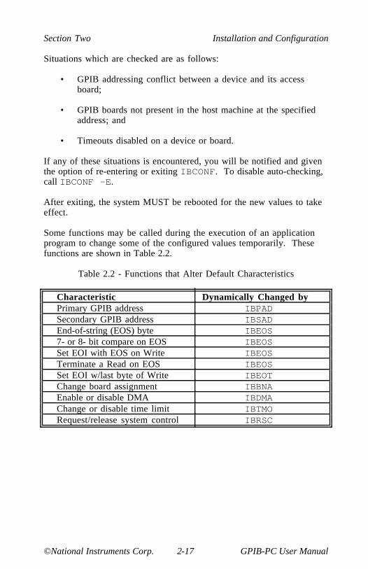
Some functions may be called during the execution of an applicationprogram to change some of the configured values temporarily. Thesefunctions are shown in Table 2.2.
Table 2.2 - Functions that Alter Default Characteristics
Characteristic Dynamically Changed byPrimary GPIB address IBPADSecondary GPIB address IBSADEnd-of-string (EOS) byte IBEOS7- or 8- bit compare on EOS IBEOSSet EOI with EOS on Write IBEOSTerminate a Read on EOS IBEOSSet EOI w/last byte of Write IBEOTChange board assignment IBBNAEnable or disable DMA IBDMAChange or disable time limit IBTMORequest/release system control IBRSC
Installation and Configuration Section Two
GPIB-PC User Manual 2-18 ©National Instruments Corp.
Using Your GPIB-PC
Now that your software and hardware are installed, read Section Threefor an introduction to the functions available for the GPIB-PC. Thefunctions are described in the order that you will most likely use them.Pay special attention to Group I, Group II, and Group III.
After reading about these functions, practice using them with yourprogrammable instrument or device in an interactive environment usingthe IBIC program described in Section Five. IBIC allows you toprogram your instrument interactively from the computer keyboard ratherthan from an application program. This helps you understand how thedevice and the handler work. It also familiarizes you with statusinformation that is returned by each function and that is also availableto your application program in the form of global variables.
While running IBIC, study the descriptions of each function given inSection Four to fully understand the purpose and syntax of eachfunction.
Finally, referring to the appropriate language supplement of SectionFour, write your application program. Whenever possible, use IBIC totest the sequence of the GPIB-PC function calls your applicationprogram makes. Trying your function calls from IBIC is especiallyhelpful if your application program responds in an unexpected manner.

©National Instruments Corp. 3-1 GPIB-PC User Manual
Section Three - GPIB-PCFunctions — Introduction
This section introduces you to the GPIB-PC handler functions and theircapabilities. They are described in the order you will most likely usethem.
Application environments for which the functions are designed aredescribed. Short examples illustrate how the functions operate.
Introduction to the GPIB-PC Functions
The GPIB-PC functions are high-level and low-level functions thatcommunicate with and control devices on the GPIB. The functions aredivided into six groups, and each group is distinguished by the type ofapplications it serves. The functions contained in the first three groupsare mostly high-level, while those of the last three are mostly low-level.
High-Level Functions
High-level functions are easy to learn and use. They automaticallyexecute sequences of commands that handle bus managementoperations required to perform activities such as reading from andwriting to devices and polling them for status. These functions free youfrom having to know the GPIB protocol or bus management detailsinvolved. Most device functions (functions that specify a device) arehigh-level functions.
Low-Level Functions
In contrast, low-level functions perform rudimentary or primitiveoperations that require that you know something about GPIB protocol touse them effectively. They are needed because high-level functions donot always meet the requirements of applications. In such cases, low-level functions offer the flexibility you need to solve most of yourapplication problems. All board functions (functions that specify aboard) are low-level functions.
Calling Syntax
The calling syntax for GPIB-PC functions varies according to thelanguage used. In this section, a generic syntax is used to identify thefunction and its arguments.

GPIB-PC Functions — Introduction Section Three
GPIB-PC User Manual 3-2 ©National Instruments Corp.
Group I
Group I functions may be the only functions you need for many of yourinstrument control applications. Group I functions are as follows:
• IBRD,
• IBWRT, and
• IBFIND.
They are suitable for your applications under the following conditions:
• Communication is between the Controller (computer) and onedevice at a time. Messages are not broadcast to severaldevices at once, and devices do not talk to each other directly.
• Devices do not require special services or operations, such aspolling or triggering, to send or receive data.
IBRD and IBWRT are high-level input/output (I/O) functions. IBFINDis a start-up function that opens the device.
IBRD (bd,buf,cnt)
IBRD reads a specified number of bytes from a device and stores themin memory. The device is automatically addressed before reading andunaddressed afterward. If not done previously, the GPIB is initialized onentering the function and the device is placed in remote programmingmode.
When programming in BASIC, IBRD performs string transfers. IBRDIis available for binary transfers to an integer array.
IBWRT (bd,buf,cnt)
IBWRT writes a specified number of bytes from the memory buffer to adevice. The device is automatically addressed before writing andunaddressed afterward. If not done previously, the GPIB is initialized onentering the function, and the device is placed in remote programmingmode.
When programming in BASIC, IBWRT performs string transfers.IBWRTI is available for binary transfers from an integer array.

Section Three GPIB-PC Functions — Introduction
©National Instruments Corp. 3-3 GPIB-PC User Manual
IBFIND (bdname,bd)
IBFIND returns a unit descriptor associated with the name of thedevice. When the software is installed, a description of each device isplaced in an internal reference table accessible by the handler. Thisdescription includes the GPIB address, end-of-string (EOS) modes,timeout selection, and a name for the device.
Group II
Group II functions offer additional high-level device services oftenneeded in common instrument control applications. Group II functionsare as follows:
• IBRSP,
• IBCLR,
• IBTRG, and
• IBLOC.
IBRSP (bd,spr)
IBRSP serially polls a device and returns its status response. Theresponse consists of a single byte in which the hex 40 bit is set if thedevice is requesting service and asserting Service Request (SRQ).
Here are examples of a Tektronix 4041 BASIC SRQ handler call andthe corresponding IBRSP call. In this case, the device being polled isthe plotter and is at GPIB address 7:
POLL STATUS, ADDRESS; 7
CALL IBRSP (PLTR%,STATUS%)
In both cases, the plotter's status response is stored in the variableSTATUS.
Unless disabled during software configuration, any device function callwill automatically conduct serial polls if SRQ is asserted on GPIB. Thisautomatic serial polling is discussed in Section Four.

GPIB-PC Functions — Introduction Section Three
GPIB-PC User Manual 3-4 ©National Instruments Corp.
IBCLR (bd)
IBCLR clears the device by sending to it the Selected Device Clear(SDC) and appropriate addressing commands.
Clearing the Device Versus Clearing the GPIB
There is a difference between clearing or initializing devices andclearing or initializing the GPIB itself.
Clearing the Device
The Selected Device Clear (SDC) command that is sent by the IBCLRfunction resets internal functions of the device, such as causing a digitalmultimeter to change its function, range, and trigger mode back todefault settings.
Clearing the GPIB
The Interface Clear (IFC) command initializes the GPIB and the businterface circuits of all attached devices without affecting internalfunctions. IFC is sent automatically when the first device function iscalled.
A device function is a function that references a device such as the fouralready described: IBRD, IBWRT, IBRSP, and IBCLR.
IBTRG (bd)
IBTRG triggers the device by sending to it the Group Execute Trigger(GET) and appropriate addressing commands.
IBLOC (bd)
IBLOC places the device in local program mode by sending the Go ToLocal (GTL) and appropriate addressing commands to the device.
Placing a Device in Remote Mode
The first device function call after power-on, in addition to sending theIFC command as previously described, also places the device in remoteprogram mode by setting the GPIB Remote Enable (REN) line andaddressing the device to listen.

Section Three GPIB-PC Functions — Introduction
©National Instruments Corp. 3-5 GPIB-PC User Manual
Placing a Device in Local Mode
Devices must usually be placed in remote program mode before theycan be programmed from the GPIB. This operation is doneautomatically by the handler. The IBLOC function is then used whenthat device must be returned to local program mode.
In addition, unless disabled using the configuration program (IBCONF),the handler places devices in local lockout mode, which prevents youfrom returning a device to local mode using the device's front-panelcontrol.
The seven previously described functions will be sufficient to meet yourapplication needs, in most cases. They are the most important functionsfor you to learn.
Group III
The functions of Group III are more flexible for controlling andcommunicating with devices. Group III functions are as follows:
• IBRDA,
• IBWRTA,
• IBRDF,
• IBWRTF,
• IBWAIT,
• IBSTOP,
• IBTMO,
• IBONL, and
• IBPCT.

GPIB-PC Functions — Introduction Section Three
GPIB-PC User Manual 3-6 ©National Instruments Corp.
These functions are used under the following conditions:
• Program execution must proceed in parallel with GPIB I/O –often called asynchronous operation.
• I/O is to or from a file rather than a memory buffer.
• Controller-In-Charge authority must be transferred to anotherGPIB device.
• The timeout value must be changed.
• The handler must be reinitialized with respect to certaindevices.
IBRDA (bd,buf,cnt) andIBWRTA (bd,buf,cnt)
These functions are similar to IBRD and IBWRT except that theoperation is asynchronous. This means that the function returns afterstarting the I/O operation without waiting for it to complete.
When programming in BASIC, IBRDA and IBWRTA perform stringtransfers. IBRDIA and IBWRTIA are available for transfers to and froman integer array.
IBRDF (bd,buf,cnt) andIBWRTF (bd,buf,cnt)
These functions are similar to IBRD and IBWRT except that data is readinto a file.
IBWAIT (bd,mask)
IBWAIT waits for one or more events to occur. For the IBRDA andIBWRTA functions, the event to wait for is the completion of theoperation.
IBSTOP (bd)
IBSTOP aborts any asynchronous operation associated with the device.
Section Three GPIB-PC Functions — Introduction
©National Instruments Corp. 3-7 GPIB-PC User Manual
IBTMO (bd,v)
IBTMO changes the time limit in which operations with the device mustcomplete.
IBONL (bd,v)
IBONL re-initializes the device and cancels any asynchronous I/O inprogress. All reconfigurable software parameters, such as the time limitjust discussed, are reset to their power-on values. See the discussion ofsoftware configuration in Section Two for further information onreconfigurable software parameters.
The last function in this group allows the computer to pass control toanother device capable of being the Controller.
IBPCT (bd)
IBPCT passes Controller-In-Charge authority to the specified device bysending the Take Control (TCT) commands and appropriate addressingcommands.
Most GPIB-compatible instruments or other types of devices can beprogrammed using the high-level functions of Groups I, II, or III. Not alldevices, however, are completely compatible with the IEEE-488specification, nor are the combinations of bus management and/or I/Ooperations contained in the high-level functions suitable for allapplications.
Some operations, such as interprocessor networks and peripheralsharing, require additional capabilities and flexibility in controlling theGPIB. This is achieved, in part, with low-level functions that performsingle GPIB activities, each with a limited scope or objective. Powerfuland versatile routines can be developed using these functions. GroupsIV, V, and VI consist mostly of low-level functions.

GPIB-PC Functions — Introduction Section Three
GPIB-PC User Manual 3-8 ©National Instruments Corp.
Group IV
The functions described previously have been device functions; that is,the bd argument referred to a device on the GPIB. This sectionintroduces board functions, where bd refers to a specific GPIB-PCinterface board in the computer. Group IV functions are as follows:
• IBFIND,
• IBCMD,
• IBCMDA,
• IBRD,
• IBRDA,
• IBWRT,
• IBWRTA,
• IBSTOP,
• IBWAIT,
• IBTMO,
• IBONL,
• IBSIC,
• IBSRE,
• IBGTS,
• IBCAC,
• IBRPP, and
• IBPPC.

Section Three GPIB-PC Functions — Introduction
©National Instruments Corp. 3-9 GPIB-PC User Manual
Group IV functions can be used under the following conditions:
• Messages are broadcast to more than one device at a time.
• Messages are sent directly from one device to another, withoutpassing through the Controller.
• GPIB lines, such as Attention (ATN), must be turned off or onin a particular fashion to ensure proper operation of a device.
• Devices must be polled in parallel rather than in serial.
Purpose of Board Functions
The handler software can control or communicate over the GPIB only bymanipulating a GPIB-PC interface board. Remote devices are accessedindirectly by programming the interface board to do specific things.Device functions are selected sequences of some basic board functions.
Board functions provide the precise control of the GPIB that is neededfor special applications.
Multiboard Capability
The handler can control or manipulate more than one interface board.This type of handler is commonly called a multiboard handler, asopposed to a single board handler in which one copy of the handler cancontrol only one board.
Figure 3.1 shows a multiboard GPIB system with board GPIB0connected to two devices, an oscilloscope and a digital voltmeter; andwith board GPIB1 connected to two other devices, a printer and aplotter.
Each board is called the access board for its attached devices becausethe board is used automatically by the device functions to access thosedevices. More information about board and device functions is providedin More About Device and Board Functions at the end of this section.

GPIB-PC Functions — Introduction Section Three
GPIB-PC User Manual 3-10 ©National Instruments Corp.
IBFIND (bdname,bd)
This is the same as the Group I function except that boards are assignednames at configuration time in the form GPIBn, where n is a board'sdecimal number (0, 1, 2, ...) within the computer. For instance, in asystem with two GPIB boards, the first is named GPIB0 and the secondGPIB1.
IBCMD (bd,buf,cnt) andIBCMDA (bd,buf,cnt)
Both functions use the specified board to write commands from memoryto the GPIB. The messages are sent synchronously using IBCMD andasynchronously using IBCMDA. These command functions are used, forexample, to address and unaddress GPIB devices and to send interfacemessages that enable and disable devices for serial and parallel polls,that clear and trigger devices, and that lock out front panel control ofdevices.
IBRD (bd,buf,cnt) andIBRDA (bd,buf,cnt)
Both functions use the specified board to read from a device that hasalready been addressed to talk (for example, by the IBCMD or IBCMDAfunction). The syntax for these low-level functions is the same as theirhigh-level counterparts of Group I and III. The software automaticallydifferentiates bd descriptors that refer to devices from those that refer toboards, and executes the read operations appropriately.
IBRDI and IBRDIA are also available in BASIC for binary transfers toan integer array.
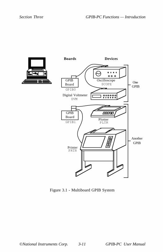
Section Three GPIB-PC Functions — Introduction
©National Instruments Corp. 3-11 GPIB-PC User Manual
Boards Devices
GPIB0
GPIB1
GPIBBoard
GPIBBoard
Oscilloscope
Digital Voltmeter
Plotter
Printer
AnotherGPIB
OneGPIB
SCOPE
DVM
PLTR
PRTR
Figure 3.1 - Multiboard GPIB System

GPIB-PC Functions — Introduction Section Three
GPIB-PC User Manual 3-12 ©National Instruments Corp.
IBWRT (bd,buf,cnt) andIBWRTA (bd,buf,cnt)
Both functions use the specified board to write to one or more devicesthat have already been addressed to listen (for example, by the IBCMDor IBCMDA function). The syntax for these low-level functions is thesame as their high-level counterparts of Group I and III. The softwareautomatically differentiates between bd descriptors that refer to devicesand those that refer to boards, and executes the write operationsappropriately.
IBWRTI and IBWRTIA are also available in BASIC for binary transfersfrom an integer array.
IBSTOP (bd)
IBSTOP aborts any asynchronous operation associated with the board.
IBWAIT (bd,mask)
IBWAIT waits for the specified board to detect one of the eventsselected in the mask bit vector to occur. These events include thecompletion of asynchronous input/output (CMPL); the board becoming atalker (TACS), listener (LACS), or Controller-In-Charge (CIC);detection of a GPIB Service Request (SRQI); assertion of the Attentionsignal (ATN); detection of the END message (END); or detection of atime limit (TIMO) or other error condition (ERR).
IBTMO (bd,v)
IBTMO changes the time limit in which operations with the board mustcomplete.
IBONL (bd,v)
IBONL performs the same initialization function for boards as the GroupIII IBONL function does for devices. In addition, the hardware as wellas the software is reset and the board is placed online (enabled) oroffline (disabled).
IBSIC (bd)
IBSIC uses the board to initialize the GPIB by sending the InterfaceClear (IFC) message.

Section Three GPIB-PC Functions — Introduction
©National Instruments Corp. 3-13 GPIB-PC User Manual
IBSRE (bd,v)
IBSRE uses the board to set or clear the GPIB Remote Enable (REN)line.
IBGTS (bd,v)
IBGTS causes the board to go from Active Controller to StandbyController, and in so doing to turn the ATN signal off. This function isgenerally used to allow two external devices to talk to each otherdirectly. The board can selectively participate in the handshake of thedata transfer and hold off the handshake when the END message isdetected. The board may then take control synchronously withoutcorrupting the transfer.
IBCAC (bd,v)
IBCAC causes the board to take control of the GPIB by setting ATN andgoing from Standby to Active Controller. The board can take controlsynchronously or asynchronously.
IBRPP (bd,buf)
IBRPP conducts a parallel poll and returns the result.
IBPPC (bd,v)
IBPPC remotely configures or unconfigures the devices for parallelpolls.
GPIB-PC Functions — Introduction Section Three
GPIB-PC User Manual 3-14 ©National Instruments Corp.
More About Device and Board Functions
Before proceeding to the next group of functions, you will find it helpfulto compare how a high-level device function can be replaced by severallow-level board functions. Conducting a serial poll is a good example.In the discussion of the IBRSP function of Group II, this BASICexample of the device function was used:
CALL IBRSP (PLTR%,STATUS%)
This is equivalent to the following sequence using the board functionsjust described:
CMD$ = "?" + CHR$(&H18) + "G!"CALL IBCMD (GPIB0%,CMD$)STATUS$ = SPACE$(1)CALL IBRD (GPIB0%,STATUS$)CMD$ = "_?" + CHR$(&H19)CALL IBCMD (GPIB0%,CMD$)
The first IBCMD function is used to send the string of ASCII commandsassigned in the first program line. These are Unlisten (?), Serial PollEnable (CHR$(&H18)), talk address of the plotter (G), and listenaddress of the board (!). Now that the plotter is enabled to send itsstatus byte and the board is addressed to receive it, the IBRD function iscalled to read the byte and store it in the variable STATUS. The finalIBCMD function completes the poll by sending the command stringconsisting of three messages: Untalk (_), Unlisten (?), and Serial PollDisable (CHR$(&H19)).
You can see that a high-level device function is easier to use. However,when an application requires a more complex serial poll routine than theone just described, such as a serial poll routine which polls severaldevices in succession and provides other servicing operations at thesame time, low-level board functions can be used to create such aroutine.
Section Three GPIB-PC Functions — Introduction
©National Instruments Corp. 3-15 GPIB-PC User Manual
Group V
Group V functions are used when the GPIB-PC is not CIC. An exampleis a system where the computer in which the board is installed performsas an instrument, but is controlled by another device on the GPIB.Group V functions are as follows:
• IBRSV,
• IBLOC,
• IBPPC,
• IBIST, and
• IBWAIT.
These functions are used to:
• Request service from the CIC.
• Simulate a front panel "return to local" switch.
• Reconfigure a board or device for a parallel poll.
• Locally configure for parallel polls and change the parallel pollflag.
• Wait for the CIC to execute certain actions.
IBRSV (bd,v)
IBRSV requests service from the CIC and to set the status byte that issent when the board is serially polled by the controller.
IBLOC (bd)
IBLOC sends a return to local message to the board. The messageclears an internal remote status condition if it is set and the internallockout status condition is not set. These conditions can be checkedwith the IBWAIT function. How the application program interprets thisaction is system dependent.

GPIB-PC Functions — Introduction Section Three
GPIB-PC User Manual 3-16 ©National Instruments Corp.
IBPPC (bd,v)
IBPPC locally configures or unconfigures the board for parallel polls.
IBIST (bd,v)
IBIST sets or clears the board's parallel poll flag (also known as theindividual status bit).
IBWAIT (bd,mask)
This function is described in Group IV. It is included here to describethe additional events associated with noncontroller operations that thefunction can detect. These include being triggered (DTAS) or cleared(DCAS) by the controller, being placed in remote programming mode(REM) by the controller, or being placed in a lockout state (LOK) bythe controller.

Section Three GPIB-PC Functions — Introduction
©National Instruments Corp. 3-17 GPIB-PC User Manual
Group VI
Group VI functions are used only when the default values of theconfiguration parameters set during software installation need to bechanged dynamically or temporarily during execution of the applicationprogram. Group VI functions are as follows:
• IBEOT,
• IBEOS,
• IBBNA,
• IBDMA,
• IBPAD,
• IBSAD,
• IBRSC, and
• IBTMO.
They are used to accomplish the following actions:
• Change the way I/O transmissions are terminated.
• Associate a device with a different access board.
• Change from DMA to programmed I/O.
• Change the GPIB address of a board or device.
• Request or release System Control.
IBEOT (bd,v)
IBEOT enables or disables sending the END message (EOI) with thelast byte written by the board.
GPIB-PC Functions — Introduction Section Three
GPIB-PC User Manual 3-18 ©National Instruments Corp.
IBEOS (bd,v)
IBEOS assigns the end of string (EOS) character to use with subsequentIBRD and IBWRT operations. This character is compared with incomingbytes from the device and may be used to terminate a read operation. Itis also compared with outgoing bytes to the device and may be used togenerate the END message (EOI).
IBBNA (bd,"GPIBn")
IBBNA assigns board n to be the access board for device bd.
IBDMA (bd,v)
IBDMA selects DMA or programmed I/O for the board. This function isonly appropriate for boards with DMA capability.
IBPAD (bd,v)
IBPAD sets the primary GPIB address of the device or board.
IBSAD (bd,v)
IBSAD sets the board's or device's secondary GPIB address or disablessecondary addressing.
IBRSC (bd,v)
IBRSC causes the board to request or release System Control authority.
IBTMO (bd,v)
IBTMO sets the time limit in which operations with a device or boardmust complete.
Another important feature of the GPIB-PC functions is that they returnstatus information about the boards and devices in the system. Thisinformation is returned in the form of three global status variables,IBSTA, IBERR, and IBCNT. The beginning of Section Four fullydescribes these variables.
©National Instruments Corp. 4-1 GPIB-PC User Manual
Section Four - GPIB-PCFunctions — Overview
This section consists of Section Four and a BASIC supplement. SectionFour contains a discussion of the important characteristics common toall programming languages. The BASIC supplement lists the GPIBfunctions for BASICA and QuickBASIC languages.
When you order a language other than BASIC, you receive a separatesupplement unless your language is very similar to BASICA. Insert anynew supplements in place of or in addition to Section Four A.
General Programming Information
The following characteristics are common to all programminglanguages:
• A Status Word,
• Error Codes,
• A Count Variable,
• Read and Write Termination,
• Device Function Calls, and
• Automatic Serial Polling.
A thorough understanding of the concepts presented here is essential tothe implementation of a GPIB system.
The next several paragraphs explain the status word (IBSTA), the errorvariable (IBERR), and the count variable (IBCNT). These variables areupdated with each function call to reflect the status of the most recentlyreferenced device or board.

GPIB-PC Functions — Overview Section Four
GPIB-PC User Manual 4-2 ©National Instruments Corp.
Status Word
All functions return a status word containing information about the stateof the GPIB and the GPIB-PC. You should test for the conditionsreported in the status word to make decisions about continuedprocessing. The status word is returned in the variable IBSTA.
The status word contains 16 bits, of which 14 are meaningful. A bitvalue of 1 indicates the corresponding condition is in effect. A bit valueof zero indicates the condition is not in effect.
Table 4.1 lists the conditions and the bit position to be tested for thatcondition. Some bits are set only on device function calls (d); somebits are set only on board function calls (b); and some bits are set oneither type (db).
Table 4.1 - Status Word Layout
Mnemonics Bit Hex Function DescriptionPos. Value Type
ERR 15 8000 db GPIB errorTIMO 14 4000 db Time limit exceededEND 13 2000 db END or EOS detectedSRQI 12 1000 b SRQ interrupt receivedRQS 11 800 d Device requestingserviceCMPL 8 100 db I/O completedLOK 7 80 b Lockout StateREM 6 40 b Remote StateCIC 5 20 b Controller-In-ChargeATN 4 10 b Attention is assertedTACS 3 8 b TalkerLACS 2 4 b ListenerDTAS 1 2 b Device Trigger StateDCAS 0 1 b Device Clear State
A description of each status word and its condition follows.
Section Four GPIB-PC Functions — Overview
©National Instruments Corp. 4-3 GPIB-PC User Manual
ERR (db) ERR is set in the status word following any call that resultsin an error; the particular error may be determined byexamining the IBERR variable. It is cleared following anycall that does not result in an error.
NOTE: Always check for an error condition after each call.An error made early in your application program may notbecome apparent until a later instruction. At that time, theerror can be more difficult to locate.
TIMO (db) TIMO specifies whether a timeout has occurred. It is set inthe status word following a call to IBWAIT if the TIMO bitof the IBWAIT mask parameter is also set and if the waithas exceeded the time limit value that is set by the IBTMOcall. It is also set following a call to any of the synchronousI/O functions (e.g., IBRD, IBWRT, and IBCMD) if a timeoutoccurs during a call. TIMO is cleared in the status word inall other circumstances.
END (db) END specifies whether the END or EOS message has beenreceived. It is set in the status word following a readfunction if the END or EOS message was detected duringthe read. While the GPIB-PC is performing a shadowhandshake as a result of the IBGTS function, any otherfunction call may return a status word with the END bit setif the END or EOS message occurred before or during thatcall. It is cleared in the status word when any I/O operationis initiated.
SRQI (b) SRQI specifies whether a device is requesting service. It isset in the status word whenever the GPIB-PC is CIC andthe GPIB SRQ line is asserted. It is cleared whenever theGPIB-PC ceases to be the CIC, or the GPIB SRQ line isunasserted. The bit is also cleared when executing boardfunctions and the GPIB-PC is an active talker, i.e., it isaddressed to talk and ATN is unasserted.
In Revision D software, the SRQI status bit always reflectsthe current level of the SRQ line whether or not the GPIB-PC is CIC.

GPIB-PC Functions — Overview Section Four
GPIB-PC User Manual 4-4 ©National Instruments Corp.
RQS (d) RQS appears only in the status word of a device functioncall. Indicates that the device is requesting service. It isset in the status word whenever the hex 40 bit is asserted inthe device's serial poll status byte. The serial poll whichobtains the status byte may be the result of an IBRSP call,or it may be done automatically by the handler. It iscleared when the user has called IBRSP to read the serialpoll status byte that caused the RQS. An IBWAIT on RQSshould only be done on devices that respond to serial polls.
CMPL (db) CMPL specifies the condition of outstanding I/O operations.It is set in the status word whenever I/O is not in progress;that is, whenever I/O is complete. It is cleared while I/O isin progress.
LOK (b) LOK specifies whether the board is in a lockout state.While LOK is set, the function IBLOC is effectivelyinoperative for that board. It is set whenever the GPIB-PCdetects the Local Lockout (LLO) message has been senteither by the GPIB-PC or by another Controller. It iscleared when the Remote Enable (REN) GPIB linebecomes unasserted either by the GPIB-PC or by anotherController.
REM (b) REM specifies whether the board is in remote state. It isset whenever the Remote Enable (REN) GPIB line isasserted and the GPIB-PC detects its listen address hasbeen sent either by the GPIB-PC or by another Controller.It is cleared whenever REN becomes unasserted, or whenthe GPIB-PC as a Listener detects the Go to Local (GTL)command has been sent either by the GPIB-PC or byanother Controller, or when the IBLOC function is calledwhile the LOK bit is cleared in the status word.
CIC (b) CIC specifies whether the GPIB-PC is the Controller-In-Charge. It is set whenever the IBSIC function is calledwhile the GPIB-PC is System Controller, or when anotherController passes control to the GPIB-PC. It is clearedwhenever the GPIB-PC detects Interface Clear (IFC) fromthe System Controller, or when the GPIB-PC passes controlto another device.
ATN (b) ATN specifies the state of the GPIB Attention (ATN) line.It is set whenever the GPIB ATN line is asserted andcleared when the ATN line is unasserted.
TACS (b) TACS specifies whether the GPIB-PC has been addressed

Section Four GPIB-PC Functions — Overview
©National Instruments Corp. 4-5 GPIB-PC User Manual
as a Talker. It is sent either by the GPIB-PC itself or byanother Controller. It is cleared whenever the GPIB-PCdetects the Untalk (UNT) command, a talk address otherthan its own talk address, or Interface Clear (IFC).
LACS (b) LACS specifies whether the GPIB-PC has been addressedas a Listener. It is set whenever the GPIB-PC detects itslisten address (and secondary address, if enabled) has beensent either by the GPIB-PC itself or by another Controller.It is also set whenever the GPIB-PC shadow handshakes asa result of the IBGTS function. It is cleared whenever theGPIB-PC detects the Unlisten (UNL) command, its owntalk address, Interface Clear (IFC), or IBGTS is calledwithout shadow handshake.
DTAS (b) DTAS specifies whether the GPIB-PC has detected adevice trigger command. It is set whenever the GPIB-PC,as a Listener, detects the Group Execute Trigger (GET)command has been sent by another Controller. It is clearedin the status word on any call immediately following anIBWAIT call if the DTAS bit is set in the IBWAIT maskparameter.
DCAS (b) DCAS specifies whether the GPIB-PC has detected adevice clear command. It is set whenever the GPIB-PCdetects the Device Clear (DCL) command has been sentby another Controller, or whenever the GPIB-PC as aListener detects the Selected Device Clear (SDC)command has been sent by another Controller. It is clearedin the status word on any call immediately following anIBWAIT call if the DCAS bit was set in the IBWAIT maskparameter, or on any call immediately following a read orwrite.
In addition to the above, the following situations also affect the statusword bits:
• A call to the function IBONL clears the following bits:
END LOK REM CIC TACS LACS DTAS DCAS
• A call to IBONL affects bits other than those listed hereaccording to the rules explained above.
In the event that a function call returns an ENEB or EDVR error, allstatus word bits except the ERR bit are cleared, since these error codesindicate that it is not possible to obtain the status of the GPIB-PC.

GPIB-PC Functions — Overview Section Four
GPIB-PC User Manual 4-6 ©National Instruments Corp.
Error Codes
When the ERR bit is set in the status word, a GPIB error has occurred.The error code is returned in the variable IBERR.
There are 14 possible error codes. Table 4.2 lists these codes, arecommended mnemonic to be associated with that type of error, andthe numeric value of the code.
Table 4.2 - GPIB Error Codes
Suggested Decimal ExplanationMnemonic ValueEDVR 0 DOS errorECIC 1 Function requires GPIB-PC to be CICENOL 2 No Listener on write functionEADR 3 GPIB-PC not addressed correctlyEARG 4 Invalid argument to function callESAC 5 GPIB-PC not System Controller as requiredEABO 6 I/O operation abortedENEB 7 Non-existent GPIB-PC boardEOIP 10 I/O started before previous operationcompletedECAP 11 No capability for operationEFSO 12 File system errorEBUS 14 Command error during device callESTB 15 Serial Poll status byte lostESRQ 16 SRQ stuck in ON position
A description of each error and some conditions under which it mayoccur follows:
EDVR (0) EDVR is returned by the language interface when thedevice or board name passed in an IBFIND call is notconfigured in the handler. In this case, the variable IBCNTwill contain the DOS error code 2, "Device not found." Theremedy is to replace the argument to IBFIND with a validboard or device name, or reconfigure the handler using theIBCONF utility to recognize the name.
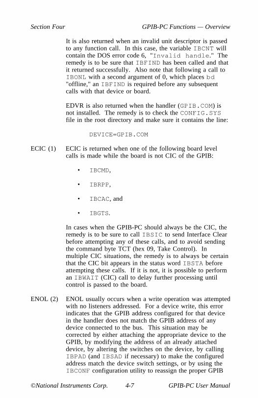
Section Four GPIB-PC Functions — Overview
©National Instruments Corp. 4-7 GPIB-PC User Manual
It is also returned when an invalid unit descriptor is passedto any function call. In this case, the variable IBCNT willcontain the DOS error code 6, "Invalid handle." Theremedy is to be sure that IBFIND has been called and thatit returned successfully. Also note that following a call toIBONL with a second argument of 0, which places bd"offline," an IBFIND is required before any subsequentcalls with that device or board.
EDVR is also returned when the handler (GPIB.COM) isnot installed. The remedy is to check the CONFIG.SYSfile in the root directory and make sure it contains the line:
DEVICE=GPIB.COM
ECIC (1) ECIC is returned when one of the following board levelcalls is made while the board is not CIC of the GPIB:
• IBCMD,
• IBRPP,
• IBCAC, and
• IBGTS.
In cases when the GPIB-PC should always be the CIC, theremedy is to be sure to call IBSIC to send Interface Clearbefore attempting any of these calls, and to avoid sendingthe command byte TCT (hex 09, Take Control). Inmultiple CIC situations, the remedy is to always be certainthat the CIC bit appears in the status word IBSTA beforeattempting these calls. If it is not, it is possible to performan IBWAIT (CIC) call to delay further processing untilcontrol is passed to the board.
ENOL (2) ENOL usually occurs when a write operation was attemptedwith no listeners addressed. For a device write, this errorindicates that the GPIB address configured for that devicein the handler does not match the GPIB address of anydevice connected to the bus. This situation may becorrected by either attaching the appropriate device to theGPIB, by modifying the address of an already attacheddevice, by altering the switches on the device, by callingIBPAD (and IBSAD if necessary) to make the configuredaddress match the device switch settings, or by using theIBCONF configuration utility to reassign the proper GPIB

GPIB-PC Functions — Overview Section Four
GPIB-PC User Manual 4-8 ©National Instruments Corp.
address to the device in the handler.
For a board write, an IBCMD call is generally necessary toaddress devices before an IBWRT. Be sure that the properlisten address is in the IBCMD argument string and that noUnlisten (hex 3F) command follows it.
ENOL may occur in situations in which the GPIB-PC is notthe CIC and the Controller asserts ATN before the writecall in progress has ended. The remedy is either to reducethe write byte count to that which is expected by theController, or to resolve the situation on the Controller'send.
EADR (3) EADR occurs when the GPIB-PC is CIC and is notaddressing itself before read and write calls are made. Thiserror is extremely unlikely to occur on a device call. For aboard call the remedy is to be sure to send the appropriateTalk or Listen address using IBCMD before attempting theIBWRT or IBRD.
EADR is also returned by the function IBGTS when theshadow-handshake feature is requested and the GPIB ATNline is already unasserted. In this case, the shadowhandshake is not possible and the error is returned to notifyyou of that fact. IBGTS should almost never be calledexcept immediately after an IBCMD call. (IBCMD causesATN to be asserted.)
EARG (4) EARG results when an invalid argument is passed to afunction call. The following are some examples:
IBTMO called with a value not in the range 0-17.
IBEOS called with meaningless bits set in the high byte ofthe second parameter.
IBPAD or IBSAD called with illegal addresses.
IBPPC called with illegal parallel poll configurations.
A board-only call made with a valid device descriptor, or adevice-only call made with a valid board descriptor.
(NOTE: EDVR is returned if the descriptor is invalid.)
ESAC (5) ESAC results when IBSIC or IBSRE is called when the

Section Four GPIB-PC Functions — Overview
©National Instruments Corp. 4-9 GPIB-PC User Manual
GPIB-PC does not have System Controller capability. Theremedy is to give the GPIB-PC that capability by callingIBRSC or by using IBCONF to configure that capabilityinto the handler.
EABO (6) EABO indicates that I/O has been canceled, usually due toa timeout condition. Other causes are IBSTOP beingcalled or the Device Clear message being received fromthe CIC.
To remedy a timeout error, if I/O is actually progressing buttimes out anyway, lengthen the timeout period with IBTMO.More frequently, however, the I/O is stuck (the Listener isnot continuing to handshake or the Talker has stoppedtalking), or the byte count in the call which timed out wasmore than the other device was expecting. Be sure thatboth parties to the transfer understand what byte count isexpected; or if possible, have the Talker use the ENDmessage to assist in early termination.
ENEB (7) ENEB occurs when there is no GPIB-PC at the I/O addressspecified in the configuration program. This happens whenthe board is not physically plugged into the system, whenthe I/O address specified during configuration does notmatch the actual board setting, or when there is a conflictin the system with the BASE I/O address. If there is amismatch between the actual board setting and the valuespecified at configuration time, either reconfigure thesoftware or change the board switches to match theconfigured value.
EOIP (10) EOIP occurs when asynchronous I/O has not completedbefore some other call was made. During asynchronousI/O, until the CMPL bit is set in IBSTA, only IBSTOP andIBWAIT calls are allowed. EOIP is returned when anyother call is attempted before the I/O completes. Theremedy is to use IBWAIT to wait for the CMPL status andthen attempt the other call.
ECAP (11) ECAP results when a particular capability has beendisabled in the handler, and a call is made which attemptsto make use of that capability. For example, if you useIBCONF to disable DMA for a board, and then try to callIBDMA to turn DMA back on, you will get this error. Theremedy is not to deny capabilities which may be neededlater, and to avoid making calls which attempt to alter ormake use of capabilities that are unalterable at runtime.

GPIB-PC Functions — Overview Section Four
GPIB-PC User Manual 4-10 ©National Instruments Corp.
EFSO (12) EFSO results when an IBRDF or IBWRTF call encounters aproblem performing a file operation. Specifically, this errorindicates the function was unable to open, create, seek,write, or close the file being accessed. The specific DOSerror code for this condition is contained in IBCNT.
EBUS (14) EBUS results when certain GPIB bus errors occur duringdevice-level calls. It is necessary in all device calls for thehandler to send command bytes to perform addressing,serial polls, and to send other bus management information.Devices are expected to accept these command byteswithin the time limit specified by the configuration programor by IBTMO. EBUS occurs if a timeout occurred duringthe sending of these command bytes. Under normaloperating circumstances, the remedy would be to find outwhich GPIB device is accepting commands abnormallyslowly and fix the problem with that device. In situationsin which slow handshaking of the commands is desirable,lengthen the time limit either with the configurationprogram or the IBTMO function.
ESTB (15) ESTB occurs only during the IBRSP call. This indicatesthat one or more serial poll status bytes which werereceived due to automatic serial polls have been discardedfor lack of room to store them. Several older status bytesare available; however, the oldest is being returned by theIBRSP call. If an occasional lost status byte is notimportant in your application, you may consider this errorcode informative only and ignore it. If your applicationcannot tolerate missing even one status byte, the remedy isto disable Automatic Serial Polling using IBCONF.
ESRQ (16) ESRQ occurs only during the IBWAIT call. This indicatesthat a wait for RQS is not possible because the GPIB SRQline is stuck on. The usual reason for this situation is thatsome device that the handler is unaware of is assertingSRQ. Since the handler does not know of this device, itwill never be serially polled and SRQ will never go away.Another reason for the situation would be that a GPIB bustester or similar equipment was forcing the SRQ line to beasserted, or that there is a cable problem involving theSRQ line. Although the occurrence of ESRQ signals adefinite GPIB problem, it will affect no GPIB operationswhatever except that the RQS bit cannot be depended onwhile the condition lasts.
Section Four GPIB-PC Functions — Overview
©National Instruments Corp. 4-11 GPIB-PC User Manual
Count Variable
The IBCNT variable is updated after each read, write, or commandfunction call with the number of bytes actually transferred by theoperation.
Read and Write Termination
The IEEE-488 specification defines two methods of identifying the lastbyte of device-dependent (data) messages. The two methods permit aTalker to send data messages of any length without the Listener(s)knowing in advance the number of bytes in the transmission. The twomethods are as follows:
• END message. In this method, the Talker asserts the EOI (EndOr Identify) signal simultaneously with transmission of the lastdata byte. By design, the Listener stops reading when it detectsa data message accompanied by EOI, regardless of the value ofthe byte.
• End-of-string (EOS) character. In this method, the Talker usesa special character at the end of its data string. By priorarrangement, the Listener stops receiving data when it detectsthat character. Either a 7-bit ASCII character or a full 8-bitbinary byte may be used.
The methods can be used individually or in combination. However, it isimportant that the Listener be properly configured to unambiguouslydetect the end of a transmission.
The GPIB-PC always terminates IBRD operations on the END message.Using the configuration program, you can accommodate all permissibleforms of read and write termination. The default configuration settingsfor read and write termination can be changed at run time using theIBEOS and IBEOT functions, if necessary.

GPIB-PC Functions — Overview Section Four
GPIB-PC User Manual 4-12 ©National Instruments Corp.
Device Function Calls
Device functions are those functions in which the unit descriptoridentifies a device rather than an interface board. There are someactivities common to all device functions that should be understoodthoroughly.
In a single board configuration in which there is only one GPIB-PC inuse, when the first device function of the program is executed, the GPIBis initialized by its controlling access board with the Interface Clear(IFC) command. The Remote Enable (REN) line on that GPIB is alsoasserted. If selected in the configuration program, the Local Lockout(LLO) command is also sent to all devices on the GPIB to place themin a lockout state. Furthermore, the device may be addressed to listenand then unaddressed before certain functions are executed. This is toensure that the device is in remote program mode.
In a multiboard configuration in which there is more than one GPIB-PC,the process is the same as previously described, with the exception thateach GPIB is initialized by its access board when the first device onthat GPIB is accessed by a device function call.
The previous descriptions assume that the GPIB-PC is the SystemController of its GPIB, which is the usual configuration. If the GPIB-PCis not the System Controller, it must be passed CIC authority from theSystem Controller to execute device functions. If the access board isnot CIC when a device function is called, the board requests servicefrom the current CIC by asserting the Service Request (SRQ) line andpassing the status response byte hex 41 when serially polled by the CIC.The handler then waits indefinitely for control to be passed to the accessboard. The computer system hangs if there is not another CIC that willpass control. This might happen, for example, if the access board issupposed to be System Controller, but it was not configured as suchduring software installation.
In Revision D software, if the access board is not CIC when the devicecall is made, the ECIC error is returned.
Also in Revision D software, because of multitasking, board-levelreconfiguration functions must not be called during device-level calls.

Section Four GPIB-PC Functions — Overview
©National Instruments Corp. 4-13 GPIB-PC User Manual
Automatic Serial Polling
If this feature is enabled, the handler automatically conducts serial pollswhen SRQ is asserted. The handler polls all active devices and storeseach positive response, i.e., those responses that have the RequestService (RQS) or hex 40 bit set in the device status byte, in a queueassociated with each device. Queues are necessary because somedevices can send multiple positive status bytes back-to-back. When apositive response from a device is received, the RQS bit of its statusword (IBSTA) is set. The polling continues until SRQ is unasserted oran error condition is undetected.
If the handler cannot locate the device requesting service (no knowndevice responds positively to the poll), or if SRQ becomes stuck on(due to a faulty instrument or cable), then a GPIB system error existswhich will interfere with the proper evaluation of the RQS bit in thedevice's status words. The error (ESRQ) will be reported to you if andwhen you issue an IBWAIT call with the RQS bit included in the waitmask. Should the error condition clear itself up, you will notice this bycalling IBWAIT with the RQS bit set in the mask, where the ESRQerror will not be reported. Aside from the difficulty caused by this errorin waiting for RQS, the error will have no detrimental effects on otherGPIB operations.
If the serial poll function IBRSP is called and one or more responseshave been received previously via the automatic serial poll feature, thenthe first queued response is returned by the IBRSP function in FIFO(first in-first out) fashion. If the RQS bit of the status word is not setwhen IBRSP is called, the function conducts a serial poll and returnswhatever response is received.
If your application requires that requests for service be noticed, youshould examine the RQS bit in the status word and call the IBRSPfunction to examine the status byte whenever it appears. It is possiblefor a device's serial poll response queue to get clogged with old statusbytes when you neglect to call IBRSP to empty the queue. This errorcondition (ESTB) is returned only by IBRSP when it becomesnecessary to report that status bytes have been discarded due to a fullqueue. If your application has no interest in SRQ or status bytes, youmay ignore the occurrence of the automatic polls. The polls occurrarely, and the error conditions described will not occur unless you usethe feature.
GPIB-PC Functions — Overview Section Four
GPIB-PC User Manual 4-14 ©National Instruments Corp.
If the handler is configured with automatic serial polling enabled, thisfeature will be disabled after a board-level I/O function call, andresumed after a device-level I/O function call. However, if any device-level I/O call results in a timeout error, this feature will be disableduntil the next I/O call completes.
NOTE: If the RQS bit of the device status word is still set after IBRSPis called, the response byte queue has at least one more response byteremaining. IBRSP should be called until RQS is cleared to gather allstored response bytes and to guard against queue overflow.
©National Instruments Corp. 4A-1 GPIB-PC User Manual
Section Four A -BASICA/QuickBASIC GPIB-PCFunction Calls
This section contains information for programming the GPIB-PC inBASICA and QuickBASIC, Versions 4.0 and earlier. The termBASICA, as used in this section, refers to Advanced IBM InterpretiveBASIC for the IBM Personal Computer. The term QuickBASIC refersto Microsoft QuickBASIC.
The programming information in this supplement can be used with allversions of BASICA and QuickBASIC unless specified otherwise.When different programming information is required that is specific to aparticular version, this information is separated and identified by aframe with the respective version number in the upper left corner. Anexample of this appears as follows:
If information is required that is specific to two versions, thisinformation is separated and identified by a frame with the two versionnumbers in the upper left corner. An example of this appears as follows:
BASICA/QuickBASIC GPIB-PC Function Calls Section Four A
GPIB-PC User Manual 4A-2 ©National Instruments Corp.
If information is required that is specific to three versions, thisinformation is separated and identified by a frame with the three versionnumbers in the upper left corner. An example of this appears as follows:
Information that is not located in a frame can be used to program theGPIB-PC in all versions of BASICA and QuickBASIC (that is, Version4.0 and earlier).
BASICA Files
The GPIB-PC distribution diskette contains four files relevant toprogramming in BASICA:
• DECL.BAS - A file containing required initialization code.
• BIB.M - The BASICA language interface which gives yourapplication program access to the handler.
• DBSAMP.BAS - A sample program using device calls.
• BBSAMP.BAS - A sample program using board calls.
QuickBASIC Files
The GPIB-PC distribution diskette contains four files relevant toprogramming in QuickBASIC. These files were copied to a subdirectorycalled GPIB-PC when you ran the installation program IBSTART.BAT.
• QBDECL.BAS - A file containing required initialization code.
• QBIB1.OBJ - Version 1.0 language interface.

Section Four A BASICA/QuickBASIC GPIB-PC Function Calls
©National Instruments Corp. 4A-3 GPIB-PC User Manual
• QBIB2.OBJ - Version 2.0 and 3.0 without coprocessor.
• QBIB_87.OBJ - Version 3.0 with coprocessor.
• QBIB_87E.OBJ - Version 3.0 coprocessor emulator mode.
• QBIB4.OBJ - Version 4.0 language interface..
• QBDECL4.BAS - Version 4.0 required initialization code..
The appropriate language interface depends on the version ofQuickBASIC used:
• DQBSAMP.BAS - A sample program using device calls.
• BQBSAMP.BAS - A sample program using board calls.
Programming Preparations for BASICA
A BASICA language code block must be executed before the main bodyof your application program.
Place the file DECL.BAS, which contains this code block, at thebeginning of the application program, with appropriate adjustments toline numbers. Refer to the BASICA MERGE command. DECL.BAScontains code which loads the file BIB.M into memory. The fileBIB.M contains the BASICA language interface to the GPIB-PChandler, and must exist in the directory currently in use.

BASICA/QuickBASIC GPIB-PC Function Calls Section Four A
GPIB-PC User Manual 4A-4 ©National Instruments Corp.
You may change function and variable names defined in the code blockif they conflict with names the application program is using. Thesubstitution must be done consistently and carefully throughout.Instructions provided in this section assume that no name substitution isnecessary and that the recommended names are used.
The GPIB status, error, and count information is returned in thevariables IBSTA%, IBERR%, and IBCNT% as described at the beginningof Section Four.
In accordance with BASICA language protocol, all function argumentsare variables, either integer or string, and their values must be assignedbefore the function call is made.
The CLEAR statement in line 1 of DECL.BAS contains a constant whichis used to determine the memory requirements of the BASICA languageinterface. For the great majority of users this constant is correct. Theconstant may be incorrect, however, if you are using a system with anextremely small amount of memory. If after BASICA is invoked itreports that there are fewer than 60000 bytes free, you may need toadjust the constant to a smaller value.
Programming Preparations for QuickBASIC
Include the following QuickBASIC statement at the beginning of yourapplication program:
COMMON SHARED IBSTA%, IBERR%, IBCNT%
This statement is included in the file QBDECL.BAS on the distributiondiskette.
The GPIB status, error, and count information is returned in thevariables IBSTA%, IBERR%, and IBCNT% as described at the beginningof Section Four.
The file QBIB*.OBJ contains the QuickBASIC language interface tothe GPIB-PC handler. Link compiled GPIB application programswritten in QuickBASIC with QBIB*.OBJ to produce an executable filepermitting access to the handler.
In accordance with QuickBASIC language protocol, all functionarguments are variables, either integer or string, and their values mustbe assigned before the function call is made.

Section Four A BASICA/QuickBASIC GPIB-PC Function Calls
©National Instruments Corp. 4A-5 GPIB-PC User Manual
To run your program from within the QuickBASIC editor use theQuickBASIC BUILDLIB command to add QBIB*.OBJ to your userlibrary, and load that library when loading QuickBASIC. For example,if you are already using a library called USERLIB.EXE, addQBIB2.OBJ to it by entering:
BUILDLIB USERLIB.OBJ QBIB2.OBJ;
Then to run QuickBASIC enter:
QB /L USERLIB.EXE
To run your program from within the QuickBASIC interactiveenvironment, use the LINK command to create a QuickLibrary. Forexample, to create a QuickLibrary called QBIB4.QLB, enter:
LINK /Q QBIB4.OBJ,,,BQLB40.LIB;
Then to run QuickBASIC enter:
QB /L QBIB4.QLB
To run your program from MS DOS, follow the instructions in theQuickBASIC User's Manual which pertain to compiling and linkingprograms. Use the file QBIB4.OBJ for linking purposes.
BASICA/QuickBASIC GPIB-PC I/O Functions
The most commonly needed I/O functions are IBRD and IBWRT. InBASICA, these functions read and write from a character string thatmay be up to 255 bytes long.
In addition, integer I/O functions (IBRDI and IBWRTI) are provided forusers whose data strings are longer than 255 bytes, or who need to
BASICA/QuickBASIC GPIB-PC Function Calls Section Four A
GPIB-PC User Manual 4A-6 ©National Instruments Corp.
perform arithmetic operations on the data and want to avoid theoverhead of converting the character bytes of IBRD and IBWRT intointeger format and back again.
IBRDI and IBWRTI are passed data in the form of an integer array,instead of a character string whose maximum length is limited to 255bytes. Using these functions, you may store more than 255 bytes in asingle buffer and do not have to convert each pair of data bytes to aninteger before doing arithmetic operations on the data. Internally, theIBWRTI function sends each integer to the GPIB in low-byte, high-byteorder. The IBRDI function reads a series of data bytes from the GPIBand stores them into the integer array in low-byte, high-byte order.
In addition to IBRDI and IBWRTI, the asynchronous functions IBRDIAand IBWRTIA are provided to perform asynchronous integer reads andwrites.
The functions are listed alphabetically by function name in this section.Table 4A.1 provides a summary of the BASICA GPIB-PC functions andTable 4A.2 provides a summary of the QuickBASIC GPIB-PC functions.
BASICA/QuickBASIC "ON SRQ" Capability
BASICA programs may be interrupted on the occurrence of the GPIBSRQ signal. When the interrupt occurs, a branch can be taken to aservice routine which determines the cause of the SRQ and takes theappropriate action.
National Instruments uses this statement to intercept SRQ interrupt andmake them available to user programs. For more complete informationregarding the operation of "ON PEN", refer to the IBM BASICA User'sManual and Microsoft QuickBASIC under the "ON PEN Statement."All the information in that section applies to both the light pen and tothe GPIB SRQ signal.
Statements such as "ON PEN" which intercept interrupts are a specialfeature of some versions of BASIC, including BASICA andQuickBASIC. These statements, however, are not usually a feature ofnon-BASIC languages and are not necessarily supported in otherNational Instruments language interfaces. To determine if this feature issupported in languages other than BASICA and QuickBASIC, refer tothe manual supplement that comes with that language.
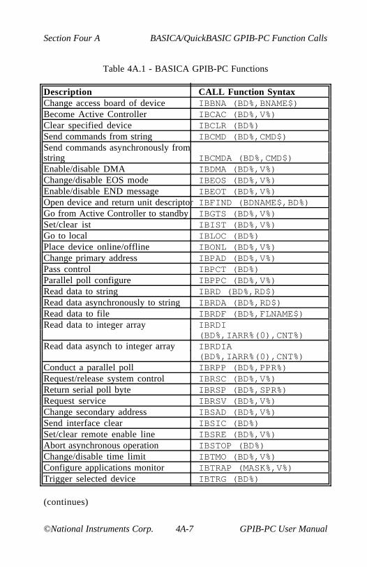
Section Four A BASICA/QuickBASIC GPIB-PC Function Calls
©National Instruments Corp. 4A-7 GPIB-PC User Manual
Table 4A.1 - BASICA GPIB-PC Functions
Description CALL Function SyntaxChange access board of device IBBNA (BD%,BNAME$)Become Active Controller IBCAC (BD%,V%)Clear specified device IBCLR (BD%)Send commands from string IBCMD (BD%,CMD$)Send commands asynchronously fromstring IBCMDA (BD%,CMD$)Enable/disable DMA IBDMA (BD%,V%)Change/disable EOS mode IBEOS (BD%,V%)Enable/disable END message IBEOT (BD%,V%)Open device and return unit descriptor IBFIND (BDNAME$,BD%)Go from Active Controller to standby IBGTS (BD%,V%)Set/clear ist IBIST (BD%,V%)Go to local IBLOC (BD%)Place device online/offline IBONL (BD%,V%)Change primary address IBPAD (BD%,V%)Pass control IBPCT (BD%)Parallel poll configure IBPPC (BD%,V%)Read data to string IBRD (BD%,RD$)Read data asynchronously to string IBRDA (BD%,RD$)Read data to file IBRDF (BD%,FLNAME$)Read data to integer array IBRDI
(BD%,IARR%(0),CNT%)Read data asynch to integer array IBRDIA
(BD%,IARR%(0),CNT%)Conduct a parallel poll IBRPP (BD%,PPR%)Request/release system control IBRSC (BD%,V%)Return serial poll byte IBRSP (BD%,SPR%)Request service IBRSV (BD%,V%)Change secondary address IBSAD (BD%,V%)Send interface clear IBSIC (BD%)Set/clear remote enable line IBSRE (BD%,V%)Abort asynchronous operation IBSTOP (BD%)Change/disable time limit IBTMO (BD%,V%)Configure applications monitor IBTRAP (MASK%,V%)Trigger selected device IBTRG (BD%)
(continues)
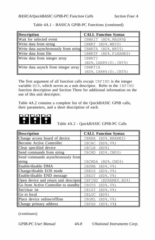
BASICA/QuickBASIC GPIB-PC Function Calls Section Four A
GPIB-PC User Manual 4A-8 ©National Instruments Corp.
Table 4A.1 - BASICA GPIB-PC Functions (continued)
Description CALL Function SyntaxWait for selected event IBWAIT (BD%,MASK%)Write data from string IBWRT (BD%,WRT$)Write data asynchronously from string IBWRTA (BD%,WRT$)Write data from file IBWRTF (BD%,FLNAME$)Write data from integer array IBWRTI
(BD%,IARR%(0),CNT%)Write data asynch from integer array IBWRTIA
(BD%,IARR%(0),CNT%)
The first argument of all function calls except IBFIND is the integervariable BD%, which serves as a unit descriptor. Refer to the IBFINDfunction description and Section Three for additional information on theuse of this unit descriptor.
Table 4A.2 contains a complete list of the QuickBASIC GPIB calls,their parameters, and a short description of each.
Table 4A.2 - QuickBASIC GPIB-PC Calls
Description CALL Function SyntaxChange access board of device IBBNA (BD%,BNAME$)Become Active Controller IBCAC (BD%,V%)Clear specified device IBCLR (BD%)Send commands from string IBCMD (BD%,CMD$)Send commands asynchronously fromstring IBCMDA (BD%,CMD$)Enable/disable DMA IBDMA (BD%,V%)Change/disable EOS mode IBEOS (BD%,V%)Enable/disable END message IBEOT (BD%,V%)Open device and return unit descriptor IBFIND (BDNAME$,BD%)Go from Active Controller to standby IBGTS (BD%,V%)Set/clear ist IBIST (BD%,V%)Go to local IBLOC (BD%)Place device online/offline IBONL (BD%,V%)Change primary address IBPAD (BD%,V%)
(continues)

Section Four A BASICA/QuickBASIC GPIB-PC Function Calls
©National Instruments Corp. 4A-9 GPIB-PC User Manual
Table 4A.2 - QuickBASIC GPIB-PC Calls (cont.)
Description CALL Function SyntaxPass control IBPCT (BD%)Parallel poll configure IBPPC (BD%,V%)Read data to string IBRD (BD%,RD$)Read data asynchronously to string IBRDA (BD%,RD$)Read data to file IBRDF (BD%,FLNAME$)Read data to integer array IBRDI (BD%,VARPTR
(IARR%(0)),CNT%)Read data asynch to integer array IBRDIA (BD%,VARPTR
(IARR%(0)),CNT%Conduct a parallel poll IBRPP (BD%,PPR%)Request/release system control IBRSC (BD%,V%)Return serial poll byte IBRSP (BD%,SPR%)Request service IBRSV (BD%,V%)Change secondary address IBSAD (BD%,V%)Send interface clear IBSIC (BD%)Set/clear remote enable line IBSRE (BD%,V%)Abort asynchronous operation IBSTOP (BD%)Change/disable time limit IBTMO (BD%,V%)Configure applications monitor IBTRAP (MASK%,V%)Trigger selected device IBTRG (BD%)Wait for selected event IBWAIT (BD%,MASK%)Write data from string IBWRT (BD%,WRT$)Write data asynchronously from string IBWRTA (BD%,WRT$)Write data from file IBWRTF (BD%,FLNAME$)Write data from integer array IBWRTI (BD%,VARPTR
(IARR%(0)),CNT%Write data asynch from integer array IBWRTIA (BD%,VARPTR
(IARR%(0)),CNT%

BASICA/QuickBASIC GPIB-PC Function Calls Section Four A
GPIB-PC User Manual 4A-10 ©National Instruments Corp.
Table 4A.3 - QuickBASIC GPIB-PC Calls
Description CALL Function SyntaxChange access board of device IBBNA (BD%,BNAME$)Become Active Controller IBCAC (BD%,V%)Clear specified device IBCLR (BD%)Send commands from string IBCMD (BD%,CMD$)Send commands asynchronously fromstring IBCMDA (BD%,CMD$)Enable/disable DMA IBDMA (BD%,V%)Change/disable EOS mode IBEOS (BD%,V%)Enable/disable END message IBEOT (BD%,V%)Open device and return unit descriptor IBFIND (BDNAME$,BD%)Go from Active Controller to Standby IBGTS (BD%,V%)Set/clear ist IBIST (BD%,V%)Go to local IBLOC (BD%)Place device online/offline IBONL (BD%,V%)Change primary address IBPAD (BD%,V%)Pass control IBPCT (BD%)Parallel poll configure IBPPC (BD%,V%)Read data to string IBRD (BD%,RD$)Read data asynchronously to string IBRDA (BD%,RD$)Read data to file IBRDF (BD%,FLNAME$)Read data to integer array IBRDI
(BD%,IARR%(),CNT%)Read data asynch to integer array IBRDIA
(BD%,IARR%(),CNT%Conduct a parallel poll IBRPP (BD%,PPR%)Request/release system control IBRSC (BD%,V%)Return serial poll byte IBRSP (BD%,SPR%)Request service IBRSV (BD%,V%)Change secondary address IBSAD (BD%,V%)Send interface clear IBSIC (BD%)Set/clear remote enable line IBSRE (BD%,V%)Abort asynchronous operation IBSTOP (BD%)
(continues)
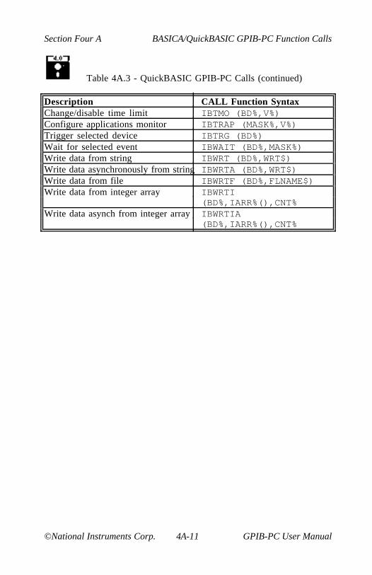
Section Four A BASICA/QuickBASIC GPIB-PC Function Calls
©National Instruments Corp. 4A-11 GPIB-PC User Manual
Table 4A.3 - QuickBASIC GPIB-PC Calls (continued)
Description CALL Function SyntaxChange/disable time limit IBTMO (BD%,V%)Configure applications monitor IBTRAP (MASK%,V%)Trigger selected device IBTRG (BD%)Wait for selected event IBWAIT (BD%,MASK%)Write data from string IBWRT (BD%,WRT$)Write data asynchronously from string IBWRTA (BD%,WRT$)Write data from file IBWRTF (BD%,FLNAME$)Write data from integer array IBWRTI
(BD%,IARR%(),CNT%Write data asynch from integer array IBWRTIA
(BD%,IARR%(),CNT%

BASICA/QuickBASIC GPIB-PC Function Calls Section Four A
GPIB-PC User Manual 4A-12 ©National Instruments Corp.
New GPIB-PC Functions
Since QuickBASIC Version 4.0 now supports true functions, thelanguage interface has been expanded to include function versions ofthe existing GPIB calls. Here are some important points to be aware of:
• All existing subroutines are still available via the CALLstatement, and existing applications do not require anychanges.
• The names of the new functions are identical to the existingsubroutines, except that the second letter of each name has been changed from B to L. For example, the subroutine IBSICis now also available as the function ILSIC.
• GPIB subroutine and function calls may be freely mixedthroughout a program.
• The include file QBDECL4.BAS contains a complete list of both subroutine and function declarations, complete with parameter list specifications to aid in type checking at compile time. You must include this file in all application programs using GPIB calls.
• In general, the functions behave identically to the subroutines with the few exceptions noted in the following paragraph. Thedescription of each subroutine found in the GPIB-PC User Manual can be applied to the new functions, except for the syntax-specific information.

Section Four A BASICA/QuickBASIC GPIB-PC Function Calls
©National Instruments Corp. 4A-13 GPIB-PC User Manual
There are a few differences between the existing subroutines and thenew functions:
• ILFIND returns a descriptor associated with the specified device.Use this value in all subsequent functions calls that access thatdevice. Normal usage would resemble the following:
BD% = ILFIND ("GPIB0")
• ILCMD, ILCMDA, ILRD, ILRDA, and ILWRTA require a thirdparameter which specifies the number of bytes to transfer. Thefunction syntax is as follows:
ILCMD (BD%, CMD$, CNT%)ILCMDA (BD%, CMD$, CNT%)ILRD (BD%, RD$, CNT%)ILRDA (BD%, RD$, CNT%)ILWRT (BD%, WRT$, CNT%)ILWRTA (BD%, WRT$, CNT%)
• All functions except ILFIND return the value of IBSTA. Thispermits the following construct:
IF IBRD (BD%, RD%, CNT%) < 0 THEN CALLGPIBERROR
Table 4A.4 contains a complete list of the new QuickBASIC GPIBfunctions, their parameters, and a short description of each.
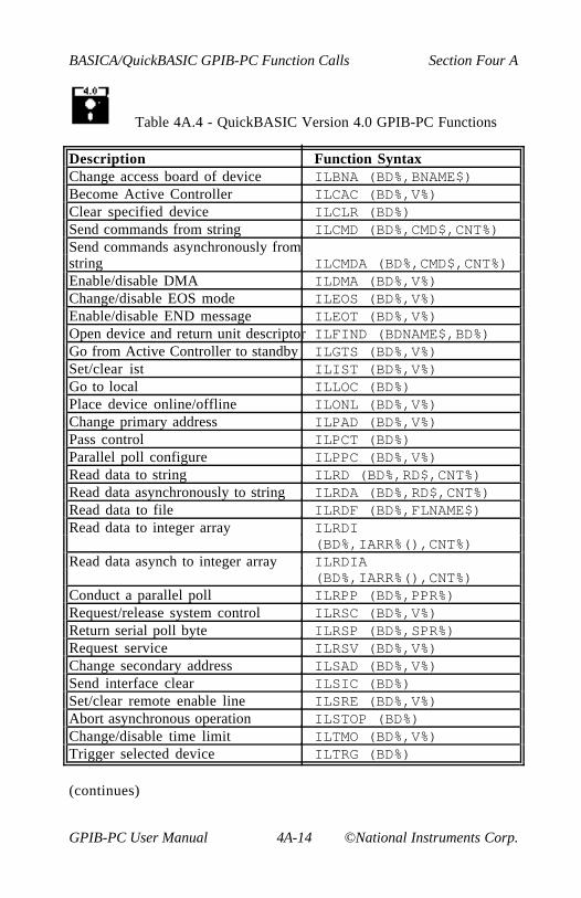
BASICA/QuickBASIC GPIB-PC Function Calls Section Four A
GPIB-PC User Manual 4A-14 ©National Instruments Corp.
Table 4A.4 - QuickBASIC Version 4.0 GPIB-PC Functions
Description Function SyntaxChange access board of device ILBNA (BD%,BNAME$)Become Active Controller ILCAC (BD%,V%)Clear specified device ILCLR (BD%)Send commands from string ILCMD (BD%,CMD$,CNT%)Send commands asynchronously fromstring ILCMDA (BD%,CMD$,CNT%)Enable/disable DMA ILDMA (BD%,V%)Change/disable EOS mode ILEOS (BD%,V%)Enable/disable END message ILEOT (BD%,V%)Open device and return unit descriptor ILFIND (BDNAME$,BD%)Go from Active Controller to standby ILGTS (BD%,V%)Set/clear ist ILIST (BD%,V%)Go to local ILLOC (BD%)Place device online/offline ILONL (BD%,V%)Change primary address ILPAD (BD%,V%)Pass control ILPCT (BD%)Parallel poll configure ILPPC (BD%,V%)Read data to string ILRD (BD%,RD$,CNT%)Read data asynchronously to string ILRDA (BD%,RD$,CNT%)Read data to file ILRDF (BD%,FLNAME$)Read data to integer array ILRDI
(BD%,IARR%(),CNT%)Read data asynch to integer array ILRDIA
(BD%,IARR%(),CNT%)Conduct a parallel poll ILRPP (BD%,PPR%)Request/release system control ILRSC (BD%,V%)Return serial poll byte ILRSP (BD%,SPR%)Request service ILRSV (BD%,V%)Change secondary address ILSAD (BD%,V%)Send interface clear ILSIC (BD%)Set/clear remote enable line ILSRE (BD%,V%)Abort asynchronous operation ILSTOP (BD%)Change/disable time limit ILTMO (BD%,V%)Trigger selected device ILTRG (BD%)
(continues)
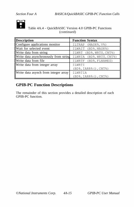
Section Four A BASICA/QuickBASIC GPIB-PC Function Calls
©National Instruments Corp. 4A-15 GPIB-PC User Manual
Table 4A.4 - QuickBASIC Version 4.0 GPIB-PC Functions(continued)
Description Function SyntaxConfigure applications monitor ILTRAP (MASK%,V%)Wait for selected event ILWAIT (BD%,MASK%)Write data from string ILWRT (BD%,WRT$,CNT%)Write data asynchronously from string ILWRTA (BD%,WRT$,CNT%)Write data from file ILWRTF (BD%,FLNAME$)Write data from integer array ILWRTI
(BD%,IARR%(),CNT%)Write data asynch from integer array ILWRTIA
(BD%,IARR%(),CNT%)
GPIB-PC Function Descriptions
The remainder of this section provides a detailed description of eachGPIB-PC function.

BASICA/QuickBASIC GPIB-PC Function Calls Section Four A
GPIB-PC User Manual 4A-16 ©National Instruments Corp.
BASICA/QuickBASIC BASICA/QuickBASICIBBNA IBBNA
Purpose: Change access board of device
Format: CALL IBBNA (BD%,BNAME$)
Remarks: BD% specifies a device. BNAME$ specifies the new accessboard to be used in all device calls to that device. IBBNAis needed only to alter the board assignment from itsconfiguration setting.
The IBBNA function identifies the board that will be usedin subsequent device functions to access the specifieddevice. IBBNA permits you to alter the association ofdevices and interface boards from the settings originallyconfigured with the configuration program.
The assignment made by this function remains in effectuntil IBBNA is called again, the IBONL or IBFINDfunction is called, or the system is rebooted. The originalconfiguration established with the configuration program isnot permanently changed.
Refer also to Table 2.1.
Device Example:
1. Associate the device DVM% with the interface board "GPIB0".
100 REM DVM is a name assigned using110 REM IBCONF.120 REM (GPIB0 is a factory default board130 REM name which cannot be changed).140 BDNAME$ = "DVM"150 CALL IBFIND (BDNAME$,DVM%)160 REM This call to IBBNA establishes170 REM GPIB0 as the access board for the180 REM device DVM%.190 BNAME$ = "GPIB0"200 CALL IBBNA (DVM%,BNAME$)

Section Four A BASICA/QuickBASIC GPIB-PC Function Calls
©National Instruments Corp. 4A-17 GPIB-PC User Manual
BASICA/QuickBASIC BASICA/QuickBASICIBCAC IBCAC
Purpose: Become Active Controller
Format: CALL IBCAC (BD%,V%)
Remarks: BD% specifies an interface board. If V% is non-zero, theGPIB-PC takes control synchronously with respect to datatransfer operations; otherwise, the GPIB-PC takes controlimmediately (and possibly asynchronously).
To take control synchronously, the GPIB-PC asserts theATN signal in such a way as to ensure that data beingtransferred on the GPIB is not corrupted. If a datahandshake is in progress, the take control action ispostponed until the handshake is complete; if a handshakeis not in progress, the take control action is doneimmediately. Synchronous take control is not guaranteed ifan IBRD or IBWRT operation completed with a timeout orerror.
Asynchronous take control should be used in situationswhere it appears to be impossible to gain controlsynchronously (e.g., after a timeout error).
It is generally not necessary to use the IBCAC function inmost applications. Functions such as IBCMD and IBRPP,which require that the GPIB-PC take control, do soautomatically.
The ECIC error results if the GPIB-PC is not CIC.
Board Examples:
1. Take control immediately without regard to any data handshakein progress.
100 V% = 0110 CALL IBCAC (BRD0%,V%)120 REM IBSTA% should show that the130 REM interface board is now CAC, i.e.,140 REM CIC with ATN asserted.
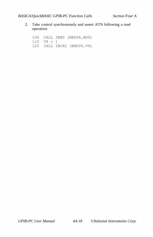
BASICA/QuickBASIC GPIB-PC Function Calls Section Four A
GPIB-PC User Manual 4A-18 ©National Instruments Corp.
2. Take control synchronously and assert ATN following a readoperation.
100 CALL IBRD (BRD0%,RD$)110 V% = 1120 CALL IBCAC (BRD0%,V%)
Section Four A BASICA/QuickBASIC GPIB-PC Function Calls
©National Instruments Corp. 4A-19 GPIB-PC User Manual
BASICA/QuickBASIC BASICA/QuickBASICIBCLR IBCLR
Purpose: Clear specified device
Format: CALL IBCLR (BD%)
Remarks: BD% specifies a device.
The IBCLR function clears the internal or device functionsof a specified device. On exit, all devices are unaddressed.
IBCLR calls the board IBCMD function to send thefollowing commands using the designated access board:
• Listen address of the device;
• Secondary address of the device, if applicable;
• Selected Device Clear (SDC); and
• Untalk (UNT) and Unlisten (UNL)
Other command bytes may be sent as necessary.
Refer to IBCMD for additional information. Refer also tothe discussion of device functions and the discussionclearing the device and clearing the GPIB in SectionThree.
Device Example:
1. Clear the device VMTR%.
100 CALL IBCLR (VMTR%)
BASICA/QuickBASIC GPIB-PC Function Calls Section Four A
GPIB-PC User Manual 4A-20 ©National Instruments Corp.
BASICA/QuickBASIC BASICA/QuickBASICIBCMD IBCMD
Purpose: Send commands from string
Format: CALL IBCMD (BD%,CMD$)
Remarks: BD% specifies an interface board. CMD$ contains thecommands to be sent over the GPIB.
The IBCMD function is used to transmit interface messages(commands) over the GPIB. These commands, which arelisted in Appendix A, include device talk and listenaddresses, secondary addresses, serial and parallel pollconfiguration messages, and device clear and triggerinstructions. The IBCMD function is also used to pass GPIBcontrol to another device. This function is NOT used totransmit programming instructions to devices.Programming instructions and other device-dependentinformation are transmitted with the read and writefunctions.
The IBCMD operation terminates on any of the followingevents:
• All commands are successfully transferred;
• Error is detected;
• Time limit is exceeded;
• Take Control (TCT) command is sent; or
• Interface Clear (IFC) message is received from theSystem Controller (not the GPIB-PC).
After termination, the IBCNT% variable contains thenumber of commands sent. A short count can occur on anyevent but the first.
An ECIC error results if the GPIB-PC is not CIC. If it is notActive Controller, it takes control and asserts ATN prior tosending the command bytes. It remains Active Controllerafterward.
Section Four A BASICA/QuickBASIC GPIB-PC Function Calls
©National Instruments Corp. 4A-21 GPIB-PC User Manual
In the examples that follow, GPIB commands andaddresses are coded as printable ASCII characters. Whenthe values to be sent over the GPIB correspond to printableASCII characters, this is the simplest means of specifyingthe values. Refer to Appendix A for conversions of numericvalues to ASCII characters.
Board Examples:
1. Unaddress all Listeners with the Unlisten (UNL or ASCII ?)command and address a Talker at &H46 (ASCII F) and aListener at &H31 (ASCII 1).
100 CMD$ = "?F1" ' UNL TAD1 LAD2110 CALL IBCMD (BRD0%,CMD$)
2. Same as Example 1, except the Listener has a secondaryaddress of &H6E (ASCII n).
100 CMD$ = "?F1n" ' UNL TAD1 LAD2 SAD2110 CALL IBCMD (BRD0%,CMD$)
3. Clear all GPIB devices (i.e., reset internal functions) with theDevice Clear (DCL or &H14) command.
100 CMD$ = CHR$ (&H14) ' DCL110 CALL IBCMD (BRD0%,CMD$)
4. Clear two devices with listen addresses of &H21 (ASCII !) and&H28 (ASCII ( (left parenthesis)) with the Selected DeviceClear (SDC or &H04) command.
100 CMD$ = "!(" + CHR$(&H04) ' LAD1 LAD2 SDC110 CALL IBCMD (BRD0%,CMD$)
5. Trigger any devices previously addressed to listen with theGroup Execute Trigger (GET or &H08) command.
100 CMD$ = CHR$(&H08) ' GET110 CALL IBCMD (BRD0%,CMD$)

BASICA/QuickBASIC GPIB-PC Function Calls Section Four A
GPIB-PC User Manual 4A-22 ©National Instruments Corp.
6. Unaddress all Listeners and serially poll a device at talkaddress &H52 (ASCII R) using the Serial Poll Enable (SPE or&H18) and Serial Poll Disable (SPD or &H19) commands (theGPIB-PC listen address is &H20 or ASCII space).
100 CMD$ ="?R " + CHR$(&H18)'UNL TAD MLA SPE110 CALL IBCMD (BRD0%,CMD$)120 RD$ = SPACE$(1) ' Declare RD buffer.130 CALL IBRD (BRD0%,RD$)140 REM After checking the status byte in150 REM RD$, disable this device and160 REM unaddress it with the Untalk.160 REM (UNT or ASCII _) command before170 REM polling the next one.180 CMD$ = CHR$(&H19) + "_" ' SPD UNT190 CALL IBCMD (BRD0%,CMD$)

Section Four A BASICA/QuickBASIC GPIB-PC Function Calls
©National Instruments Corp. 4A-23 GPIB-PC User Manual
BASICA/QuickBASIC BASICA/QuickBASICIBCMDA IBCMDA
Purpose: Send commands asynchronously from string
Format: CALL IBCMDA (BD%,CMD$)
Remarks: BD% specifies an interface board. CMD$ contains thecommands to be sent over the GPIB.
The IBCMDA function is used to transmit interfacemessages (commands) over the GPIB. These commands,which are listed in Appendix A, include device talk andlisten addresses, secondary addresses, serial and parallelpoll configuration messages, and device clear and triggerinstructions. The IBCMDA function is also used to passGPIB control to another device. This function is NOT usedto transmit programming instructions to devices.Programming instructions and other device-dependentinformation are transmitted with the write and readfunctions.
IBCMDA is used in place of IBCMD when the applicationprogram must perform other functions while processing theGPIB I/O operation. IBCMDA returns after starting the I/Ooperation. If the number of bytes to send is small and thebytes are accepted quickly by the GPIB device(s), theoperation may complete on the initial call. In this case,the CMPL bit will be set in IBSTA%. If the operation doesnot complete on the initial call, you should monitor theIBSTA% variable after subsequent calls (usually IBWAITcalls) to know that the I/O is completed. When CMPLbecomes set in IBSTA%, indicating that the I/O iscomplete, the number of bytes sent is reported in theIBCNT% variable.
Between the issuing of the IBCMDA call and thecorresponding CMPL, other GPIB function calls to thisboard will return the error EOIP, with the followingexceptions:
• IBSTOP - to cancel the asynchronous I/O;
• IBWAIT - to monitor other GPIB conditions; and

BASICA/QuickBASIC GPIB-PC Function Calls Section Four A
GPIB-PC User Manual 4A-24 ©National Instruments Corp.
• IBONL - to cancel the I/O and reset the interface.
The asynchronous I/O started by IBCMDA terminates for thesame reasons IBCMD terminates.
An ECIC error results if the GPIB-PC is not CIC. If it is notActive Controller, the GPIB-PC takes control and assertsATN prior to sending the command bytes. It remainsActive Controller afterward. The ENOL error does NOToccur if there are no Listeners.
Board Example:
1. Address several devices for a broadcast message to followwhile testing for a high priority event to occur.
100 REM The interface board BRD0% at talk110 REM address &H40 (ASCII @), addresses120 REM nine Listeners at addresses &H31-130 REM &H39 (ASCII 1-9) to receive the140 REM broadcast message.150 CMD$ = "?@123456789" ' UNL MTA160 ' LAD1...LAD9170 CALL IBCMDA (BRD0%,CMD$)180 MASK% = $4100 ' Wait for timeout or190 ' I/O completion.200 CALL EVENTTST ' Unspecified routine210 ' to test and process220 ' a high priority230 ' event.240 CALL IBWAIT (BRD0%,MASK%)250 REM Loop until complete while no error260 REM has occurred.270 IF (IBSTA% AND &H100) = 0 GOTO 180
Section Four A BASICA/QuickBASIC GPIB-PC Function Calls
©National Instruments Corp. 4A-25 GPIB-PC User Manual
BASICA/QuickBASIC BASICA/QuickBASICIBDMA IBDMA
Purpose: Enable or disable DMA
Format: CALL IBDMA (BD%,V%)
Remarks: BD% specifies an interface board. If V% is non-zero, DMAtransfers between the GPIB-PC and memory are used forread and write operations. If V% is zero, programmed I/O isused in place of DMA I/O.
If you enabled DMA at configuration time, assigning DMAchannel 1, 2, or 3, this function can be used to switchbetween programmed I/O and DMA using the selectedchannel. If you disabled DMA at configuration time,calling this function with V% equal to a non-zero valueresults in an ECAP error.
The assignment made by this function remains in effectuntil IBDMA is called again, the IBONL or IBFINDfunction is called, or the system is rebooted.
When IBDMA is called and an error does not occur, theprevious value of V% is stored in IBERR%.
On machines without DMA capability, calling this functionwith V% = 0 has no effect, and calling it with a non-zero V%results in an ECAP error.
Refer also to Table 2.1.
Board Examples:
1. Enable DMA transfers using the previously configured channel.
100 V% = 1 ' Any non-zero value will do.110 CALL IBDMA (BRD0%,V%)
2. Disable DMAs and use programmed I/O exclusively.
100 V% = 0110 CALL IBDMA (BRD0%,V%)

BASICA/QuickBASIC GPIB-PC Function Calls Section Four A
GPIB-PC User Manual 4A-26 ©National Instruments Corp.
BASICA/QuickBASIC BASICA/QuickBASICIBEOS IBEOS
Purpose: Change or disable end-of-string termination mode
Format: CALL IBEOS (BD%,V%)
Remarks: BD% specifies a device or an interface board. V% specifiesthe EOS character and the data transfer termination methodaccording to Table 4A.5. IBEOS is needed only to alter thevalue from its configuration setting.
The assignment made by this function remains in effectuntil IBEOS is called again, the IBONL or IBFINDfunction is called, or the system is rebooted.
When IBEOS is called and an error does not occur, theprevious value of V% is stored in IBERR%.
Table 4A.5 - Data Transfer Termination Method
Method Value of V%High Byte Low Byte
A. Terminate read when EOS 00000100 EOSis detected
B. Set EOI with EOS on write 00001000 EOSfunction
C. Compare all 8 bits of EOS 00010000 EOSbyte rather than low 7 bits(all read and write functions)
Methods A and C determine how read operations terminate.If Method A alone is chosen, reads terminate when the low7 bits of the byte that is read match the low 7 bits of theEOS character. If Methods A and C are chosen, a full 8-bitcomparison is used.
Section Four A BASICA/QuickBASIC GPIB-PC Function Calls
©National Instruments Corp. 4A-27 GPIB-PC User Manual
Methods B and C together determine when write operationssend the END message. If Method B alone is chosen, theEND message is sent automatically with the EOS bytewhen the low 7 bits of that byte match the low 7 bits of theEOS character. If Methods B and C are chosen, a full 8-bitcomparison is used.
Note that defining an EOS byte for a device or board doesnot cause the handler to automatically send that byte whenperforming IBWRTs. To send the EOS byte, yourapplication program must include it in the data string itdefines.
Device IBEOS Function:
When BD% specifies a device, the options coded in V% are used for alldevice reads and writes in which that device is specified.
Board IBEOS Function:
When BD% specifies a board, the options coded in V% becomeassociated with all board reads and writes.
Refer also to IBEOT and Table 2.1.
Device Example:
1. Send END when the linefeed character is written to the deviceDVM%.
10 EOSV% = &H0A ' EOS info for IBEOS.::100 V% = EOSV% + &H0800110 CALL IBEOS (DVM%,V%)120 WRT$ = "123" + CHR$(&H0A)130 ' Data bytes to be140 ' written. EOS150 ' character is the160 ' last byte.170 CALL IBWRT (DVM%,WRT$)

BASICA/QuickBASIC GPIB-PC Function Calls Section Four A
GPIB-PC User Manual 4A-28 ©National Instruments Corp.
Board Examples:
1. Program the interface board BRD0% to terminate a read ondetection of the linefeed character (&H0A) that is expected tobe received within 200 bytes.
10 EOSV% = &H0A::100 V% = EOSV% + &H0400110 CALL IBEOS (BRD0%,V%)120 REM Assume board has been addressed; do130 REM board read.140 RD$ = SPACE$(200)150 CALL IBRD (BRD0%,RD$)160 REM The END bit in IBSTA% is set if the170 REM read terminated on the EOS180 REM character. The value of IBCNT%190 REM shows the number of bytes received.
2. To program the interface board BRD0% to terminate readoperations on the 8-bit value &H82 rather than the 7-bitcharacter &H0A, change lines 10 and 100 in Example 1.
10 EOSV% = &H82::100 V% = EOSV% + &H1400::
3. To disable read termination on receiving the EOS character foroperations involving the interface board BRD0%, change line100 in Example 1.
::100 V% = EOSV%
Section Four A BASICA/QuickBASIC GPIB-PC Function Calls
©National Instruments Corp. 4A-29 GPIB-PC User Manual
4. Send END when the linefeed character is written for operationsinvolving the interface board BRD0%.
10 EOSV% = &H0A ' EOS info for IBEOS.::100 V% = EOSV% + &H0800110 CALL IBEOS (BRD0%,V%)120 REM Assume the board has been130 REM addressed; do board write.140 WRT$ = "123" + CHR$(&H0A)150 CALL IBWRT (BRD0%,WRT$)
5. To send END with linefeeds and to terminate reads on linefeedsfor operations involving the interface board BRD0%, change line100 in Example 4.
::100 V% = EOSV% + &H0C00
BASICA/QuickBASIC GPIB-PC Function Calls Section Four A
GPIB-PC User Manual 4A-30 ©National Instruments Corp.
BASICA/QuickBASIC BASICA/QuickBASICIBEOT IBEOT
Purpose: Enable or disable END termination message on writeoperations
Format: CALL IBEOT (BD%,V%)
Remarks: BD% specifies a device or an interface board. If V% is non-zero, the END message is sent automatically with the lastbyte of each write operation. If V% is zero, END is not sent.IBEOT is needed only to alter the value from theconfiguration setting.
The END message is sent when the GPIB EOI signal isasserted during a data transfer and it is used to identify thelast byte of a data string without having to use an end-of-string character. IBEOT is used primarily to send variablelength binary data.
The assignment made by this function remains in effectuntil IBEOT is called again, the IBONL or IBFINDfunction is called, or the system is rebooted.
When IBEOT is called and an error does not occur, theprevious value of V% is stored in IBERR%.
Device IBEOT Function:
When BD% specifies a device, the END termination message methodthat is selected is used on all device I/O write operations to that device.
Board IBEOT Function:
When BD% specifies an interface board, the method that is selected isused on all board-level I/O write operations, regardless of what device iswritten to.
Refer also to IBEOS and to Table 2.1.

Section Four A BASICA/QuickBASIC GPIB-PC Function Calls
©National Instruments Corp. 4A-31 GPIB-PC User Manual
Device Example:
1. Send the END message with the last byte of all subsequentwrites to the device PLOTTER%.
100 V% = 1 ' Enable sending of EOI.110 CALL IBEOT (PLOTTER%,V%)120 REM It is assumed that WRT$ contains130 REM the data to be written to the GPIB.140 CALL IBWRT (PLOTTER%,WRT$)
Board Examples:
1. Stop sending END with the last byte for calls directed to theinterface board BRD0%.
100 V% = 0 ' Disable sending of EOI.110 CALL IBEOT (BRD0%,V%)::
2. Send the END message with the last byte of all subsequentwrite operations directed to the interface board BRD0%.
100 V% = 1 ' Enable sending of EOI.110 CALL IBEOT (BRD0%,V%)120 REM It is assumed that WRT$ contains130 REM the data to be written and all140 REM Listeners have been addressed.150 CALL IBWRT (BRD0%,WRT$)
BASICA/QuickBASIC GPIB-PC Function Calls Section Four A
GPIB-PC User Manual 4A-32 ©National Instruments Corp.
BASICA/QuickBASIC BASICA/QuickBASICIBFIND IBFIND
Purpose: Open device and return the unit descriptor associated withthe given name
Format: CALL IBFIND (BDNAME$,BD%)
Remarks: BDNAME$ is a string containing a default or configureddevice or board name. BD% is a variable containing theunit descriptor returned by IBFIND.
IBFIND returns a number that is used in each function toidentify the particular device or board that is used or is theobject of that function. Calling IBFIND is required toassociate a variable name in the application program witha particular default or configured device or board name.The name used in the BDNAME$ argument must matchexactly the default or configured device or board name.The number returned, referred throughout this manual as aunit descriptor, is assigned here to the variable BD%, whichis used in all references to that device or board in GPIBfunction calls.
IBFIND performs the equivalent of IBONL to open thespecified device or board and to initialize softwareparameters to their default configuration settings. Thevariable name selected should suggest the actual name ofthe device or board in order to simplify programming effort.
If the IBFIND call fails, a negative number is returned inplace of the unit descriptor. The most probable reason for afailure is that the string argument passed into IBFIND doesnot match the default or configured device or board name.
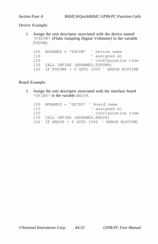
Section Four A BASICA/QuickBASIC GPIB-PC Function Calls
©National Instruments Corp. 4A-33 GPIB-PC User Manual
Device Example:
1. Assign the unit descriptor associated with the device named"FSDVM" (Fluke Sampling Digital Voltmeter) to the variableFSDVM%.
100 BDNAME$ = "FSDVM" ' Device name110 ' assigned at120 ' configuration time130 CALL IBFIND (BDNAME$,FSDVM%)140 IF FSDVM% < 0 GOTO 1000 ' ERROR ROUTINE
Board Example:
1. Assign the unit descriptor associated with the interface board"GPIB0" to the variable BRD0%.
100 BDNAME$ = "GPIB0" ' Board name110 ' assigned at120 ' configuration time130 CALL IBFIND (BDNAME$,BRD0%)140 IF BRD0% < 0 GOTO 1000 ' ERROR ROUTINE

BASICA/QuickBASIC GPIB-PC Function Calls Section Four A
GPIB-PC User Manual 4A-34 ©National Instruments Corp.
BASICA/QuickBASIC BASICA/QuickBASICIBGTS IBGTS
Purpose: Go from Active Controller to Standby
Format: CALL IBGTS (BD%,V%)
Remarks: BD% specifies an interface board. If V% is non- zero, theGPIB-PC shadow handshakes the data transfer as anAcceptor, and when the END message is detected, theGPIB-PC enters a Not Ready For Data (NRFD) handshakeholdoff state on the GPIB. If V% is zero, no shadowhandshake or holdoff is done.
The IBGTS function causes the GPIB-PC to go to theController Standby state and to unassert the ATN signal ifit initially is the Active Controller. IBGTS permits GPIBdevices to transfer data without the GPIB-PC being a partyto the transfer.
If the shadow handshake option is activated, the GPIB-PCparticipates in data handshake as an Acceptor withoutactually reading the data. It monitors the transfers for theEND (EOI or end-of-string character) message and holds offsubsequent transfers. This mechanism allows the GPIB-PCto take control synchronously on a subsequent operationsuch as IBCMD or IBRPP.
Before performing an IBGTS with shadow-handshake, theIBEOS function should be called to establish the properend-of-string character or to disable EOS detection if theend-of-string character in use by the talker is not known.
The ECIC error results if the GPIB-PC is not CIC.
Refer also to IBCAC.
In the example that follows, GPIB commands andaddresses are coded as printable ASCII characters. Whenthe hex values to be sent over the GPIB correspond toprintable ASCII characters, this is the simplest means ofspecifying the values. Refer to Appendix A for conversionsof hex values to ASCII characters.
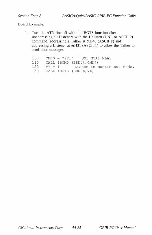
Section Four A BASICA/QuickBASIC GPIB-PC Function Calls
©National Instruments Corp. 4A-35 GPIB-PC User Manual
Board Example:
1. Turn the ATN line off with the IBGTS function afterunaddressing all Listeners with the Unlisten (UNL or ASCII ?)command, addressing a Talker at &H46 (ASCII F) andaddressing a Listener at &H31 (ASCII 1) to allow the Talker tosend data messages.
100 CMD$ = "?F1" ' UNL MTA1 MLA2110 CALL IBCMD (BRD0%,CMD$)120 V% = 1 ' Listen in continuous mode.130 CALL IBGTS (BRD0%,V%)

BASICA/QuickBASIC GPIB-PC Function Calls Section Four A
GPIB-PC User Manual 4A-36 ©National Instruments Corp.
BASICA/QuickBASIC BASICA/QuickBASICIBIST IBIST
Purpose: Set or clear individual status bit for Parallel Polls
Format: CALL IBIST (BD%,V%)
Remarks: BD% specifies an interface board. If V% is non-zero, theindividual status bit is set. If V% is zero, the bit is cleared.
The IBIST function is used when the GPIB-PCparticipates in a parallel poll that is conducted by anotherdevice that is the Active Controller. The Active Controllerconducts a parallel poll by asserting the EOI signal to sendthe Identify (IDY) message. While this message is active,each device which has been configured to participate in thepoll responds by asserting a predetermined GPIB data lineeither true or false, depending on the value of its local istbit. The GPIB-PC, for example, can be assigned to drivethe DIO3 data line true if ist=1 and false if ist=0;conversely, it can be assigned to drive DIO3 true if ist=0and false if ist=1.
The relationship between the value of ist, the line that isdriven, and the sense at which the line is driven isdetermined by the Parallel Poll Enable (PPE) message ineffect for each device. The GPIB-PC is capable ofreceiving this message either locally, via the IBPPCfunction, or remotely, via a command from the ActiveController. Once the PPE message is executed, the IBISTfunction changes the sense at which the line is drivenduring the parallel poll, and in this fashion the GPIB-PCcan convey a one-bit, device dependent message to theController.
When IBIST is called and an error does not occur, theprevious value of ist is stored in IBERR%.
Refer also to IBPPC and Table 2.1.

Section Four A BASICA/QuickBASIC GPIB-PC Function Calls
©National Instruments Corp. 4A-37 GPIB-PC User Manual
Board Examples:
1. Set the individual status bit.
100 V% = 1 ' Any non-zero value will do.110 CALL IBIST (BRD0%,V%)
2. Clear the individual status bit.
100 V% = 0110 CALL IBIST (BRD0%,V%)
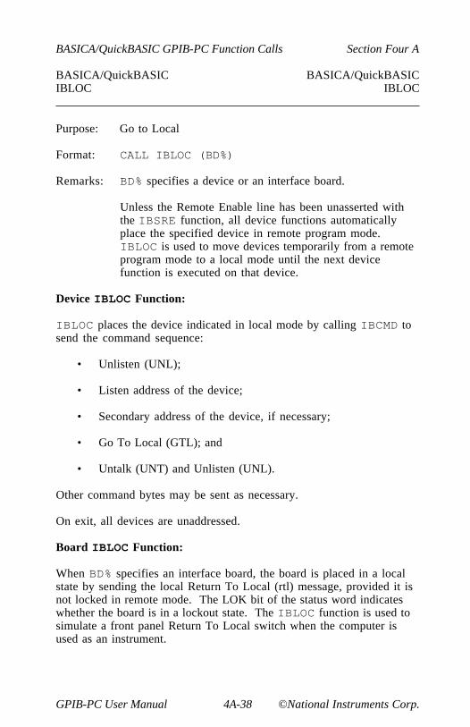
BASICA/QuickBASIC GPIB-PC Function Calls Section Four A
GPIB-PC User Manual 4A-38 ©National Instruments Corp.
BASICA/QuickBASIC BASICA/QuickBASICIBLOC IBLOC
Purpose: Go to Local
Format: CALL IBLOC (BD%)
Remarks: BD% specifies a device or an interface board.
Unless the Remote Enable line has been unasserted withthe IBSRE function, all device functions automaticallyplace the specified device in remote program mode.IBLOC is used to move devices temporarily from a remoteprogram mode to a local mode until the next devicefunction is executed on that device.
Device IBLOC Function:
IBLOC places the device indicated in local mode by calling IBCMD tosend the command sequence:
• Unlisten (UNL);
• Listen address of the device;
• Secondary address of the device, if necessary;
• Go To Local (GTL); and
• Untalk (UNT) and Unlisten (UNL).
Other command bytes may be sent as necessary.
On exit, all devices are unaddressed.
Board IBLOC Function:
When BD% specifies an interface board, the board is placed in a localstate by sending the local Return To Local (rtl) message, provided it isnot locked in remote mode. The LOK bit of the status word indicateswhether the board is in a lockout state. The IBLOC function is used tosimulate a front panel Return To Local switch when the computer isused as an instrument.

Section Four A BASICA/QuickBASIC GPIB-PC Function Calls
©National Instruments Corp. 4A-39 GPIB-PC User Manual
Device Example:
1. Return the device DVM% to local state.
100 CALL IBLOC (DVM%)
Board Example:
1. Return the interface board BRD0% to local state.
100 CALL IBLOC (BRD0%)

BASICA/QuickBASIC GPIB-PC Function Calls Section Four A
GPIB-PC User Manual 4A-40 ©National Instruments Corp.
BASICA/QuickBASIC BASICA/QuickBASICIBONL IBONL
Purpose: Place the device or interface board online or offline
Format: CALL IBONL (BD%,V%)
Remarks: BD% specifies a device or an interface board. If V% is non-zero, the device or interface board is enabled for operation(i.e., online). If V% is zero, it is held in a reset, disabledmode (offline).
Taking a device or interface board offline may be thoughtof as disconnecting its GPIB cable from the other devices.
IBONL can also be used to restore the default configurationsettings of a device or interface board. Calling IBONL withV% non-zero when the device or interface board is alreadyonline simply has the effect of restoring all configurationsettings to their defaults.
Device Examples:
1. Disable the device PLOTTER%.
100 V% = 0110 CALL IBONL (PLOTTER%,V%)
2. Enable the device PLOTTER% after taking it offline temporarily.
100 BDNAME$ = "PLOTTER" ' Device name110 'assigned at configuration time.120 CALL IBFIND (BDNAME$,PLOTTER%)130 REM IBONL with V% non-zero is140 REM automatically performed as part of150 REM IBFIND.
3. Reset the configuration settings of the device PLOTTER% totheir defaults.
100 V% = 1110 CALL IBONL (PLOTTER%,V%)

Section Four A BASICA/QuickBASIC GPIB-PC Function Calls
©National Instruments Corp. 4A-41 GPIB-PC User Manual
Board Examples:
1. Disable the interface board BRD0%.
100 V% = 0110 CALL IBONL (BRD0%,V%)
2. Enable the interface board BRD0% after taking it offlinetemporarily.
100 BDNAME$ = "GPIB0" 'Board name assigned110 'at configuration time120 CALL IBFIND (BDNAME$,BRD0%)130 REM IBONL with V% non-zero is140 REM automatically performed as part of150 REM IBFIND.
3. Reset the configuration settings of the interface board BRD0% totheir defaults.
100 V% = 1110 CALL IBONL (BRD0%,V%)

BASICA/QuickBASIC GPIB-PC Function Calls Section Four A
GPIB-PC User Manual 4A-42 ©National Instruments Corp.
BASICA/QuickBASIC BASICA/QuickBASICIBPAD IBPAD
Purpose: Change Primary Address
Format: CALL IBPAD (BD%,V%)
Remarks: BD% specifies a device or an interface board. V% specifiesthe primary GPIB address of the device or interface board.IBPAD is needed only to alter the value from itsconfiguration setting.
Only the low five bits of V% are significant and they mustnot all be ones. Thus there are 31 valid GPIB addresses,ranging from 0 to &H1E. An EARG error results if thevalue of V% is not in this range.
The assignment made by this function remains in effectuntil IBPAD is called again, the IBONL or IBFINDfunction is called, or the system is rebooted.
When IBPAD is called and an error does not occur, theprevious value of ist is stored in IBERR%. The previousprimary address is returned in IBERR%.
Device IBPAD Function:
When BD% specifies a device, IBPAD determines the talk and listenaddresses based on the value of V% for use in all I/O directed to thatdevice. A device listen address is formed by adding &H20 to theprimary address; the talk address is formed by adding &H40 to theprimary address. Consequently, a primary address of &H10 correspondsto a Listen address of &H30 and a talk address of &H50. The actualGPIB address of any device is set within that device, either withhardware switches or a software program. Refer to the devicedocumentation for instructions.
Board IBPAD Function:
When BD% specifies a board, IBPAD programs the interface board torespond to the primary talk and listen address indicated by V%.
Refer also to IBSAD, IBONL, and Table 2.1.
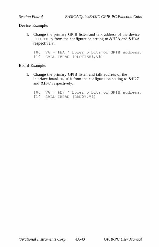
Section Four A BASICA/QuickBASIC GPIB-PC Function Calls
©National Instruments Corp. 4A-43 GPIB-PC User Manual
Device Example:
1. Change the primary GPIB listen and talk address of the devicePLOTTER% from the configuration setting to &H2A and &H4Arespectively.
100 V% = &HA ' Lower 5 bits of GPIB address.110 CALL IBPAD (PLOTTER%,V%)
Board Example:
1. Change the primary GPIB listen and talk address of theinterface board BRD0% from the configuration setting to &H27and &H47 respectively.
100 V% = &H7 ' Lower 5 bits of GPIB address.110 CALL IBPAD (BRD0%,V%)

BASICA/QuickBASIC GPIB-PC Function Calls Section Four A
GPIB-PC User Manual 4A-44 ©National Instruments Corp.
BASICA/QuickBASIC BASICA/QuickBASICIBPCT IBPCT
Purpose: Pass Control
Format: CALL IBPCT (BD%)
Remarks: BD% specifies a device.
The IBPCT function passes CIC authority to the specifieddevice from the access board assigned to that device. Theboard automatically goes to Controller Idle State (CIDS).The function assumes that the device has Controllercapability.
IBPCT calls the board IBCMD function to send thefollowing commands:
• Talk address of the device;
• Secondary address of the device, if applicable; and
• Take Control (TCT).
Other command bytes may be sent as necessary.
Refer to IBCMD for additional information.
Device Example:
1. Pass control to the device IBMXT%.
100 CALL IBPCT (IBMXT%)
Section Four A BASICA/QuickBASIC GPIB-PC Function Calls
©National Instruments Corp. 4A-45 GPIB-PC User Manual
BASICA/QuickBASIC BASICA/QuickBASICIBPPC IBPPC
Purpose: Parallel Poll Configure
Format: CALL IBPPC (BD%,V%)
Remarks: BD% specifies a device or an interface board. V% must be avalid parallel poll enable/disable command, or zero.
When IBPPC is called and an error does not occur, theprevious value of ist is stored in IBERR%.
Device IBPPC Function:
When BD% specifies a device, the IBPPC function enables or disablesthe device from responding to parallel polls.
IBPPC calls the board IBCMD function to send the followingcommands:
• Listen address of the device;
• Secondary address of the device, if applicable;
• Parallel Poll Configure (PPC); and
• Parallel Poll Enable (PPE) or Disable (PPD)
Other command bytes are sent if necessary.
Each of the 16 PPE messages specifies the GPIB data line (DIO1through DIO8) and sense (one or zero) that the device must use whenresponding to the Identify (IDY) message during a parallel poll. Theassigned message is interpreted by the device along with the currentvalue of the individual status (ist) bit to determine if the selected line isdriven true or false. For example, if the PPE=&H64, DIO5 is driven trueif ist=0 and false if ist=1. And if PPE=&H68, DIO1 is driven true ifist=1 and false if ist=0. Any PPD message or zero value cancels thePPE message in effect.
BASICA/QuickBASIC GPIB-PC Function Calls Section Four A
GPIB-PC User Manual 4A-46 ©National Instruments Corp.
Which PPE and PPD messages are sent and the meaning of a particularparallel poll response are all system dependent protocol matters to bedetermined by you.
On exit, all devices are unaddressed.
Board IBPPC Function:
When BD% specifies an interface board, the board itself is programmedto respond to a parallel poll by setting its local poll enable (lpe)message to the value of V%.
Refer also to IBCMD, IBIST, and Table 2.1 for additional information.
Device Examples:
1. Configure the device DVM% to respond to a parallel poll bysending data line DIO5 true (ist=0).
100 V% = &H64110 CALL IBPPC (DVM%,V%)
2. Configure the device DVM% to respond to a parallel poll bysending data line DIO1 true (ist=1).
100 V% = &H68110 CALL IBPPC (DVM%,V%)
3. Cancel the parallel poll configuration of the device DVM%.
100 V% = &H70110 CALL IBPPC (DVM%,V%)
Board Example:
1. Configure the interface board BRD0% to respond to a parallelpoll by sending data line DIO5 true (ist=0).
100 V% = &H64110 CALL IBPPC (BRD0%,V%)

Section Four A BASICA/QuickBASIC GPIB-PC Function Calls
©National Instruments Corp. 4A-47 GPIB-PC User Manual
BASICA/QuickBASIC BASICA/QuickBASICIBRD IBRD
Purpose: Read data to string
Format: CALL IBRD (BD%,RD$)
Remarks: BD% specifies a device or an interface board. RD$identifies the storage buffer for data bytes that are readfrom the GPIB.
The IBRD function reads from 1 to 255 bytes of data from aGPIB device. In QuickBASIC the IBRD function readsfrom 1 to 32K bytes of data from a GPIB device.
Device IBRD Function:
When BD% specifies a device, the following board steps are performedautomatically to read from the device:
1. The IBCMD function is called to address the device to talk andthe access board to listen.
2. The board IBRD function is called to read the data from thedevice, as explained in the following discussion.
3. The IBCMD function is called to unaddress the access boardand unaddress all devices using the Untalk and Unlistencommands.
Other command bytes may be sent as necessary.
When the device IBRD function returns, IBSTA% holds the latestdevice status; IBCNT% is the actual number of data bytes read from thedevice; and IBERR% is the first error detected if the ERR bit in IBSTA%is set.
Board IBRD Function:
When BD% specifies an interface board, the IBRD function attempts toread from a GPIB device that is assumed to already be properlyinitialized and addressed.
If the access board is CIC, the IBCMD function must be called prior toIBRD to address a device to talk and the board to listen. Otherwise, thedevice on the GPIB that is the CIC must perform the addressing.
BASICA/QuickBASIC GPIB-PC Function Calls Section Four A
GPIB-PC User Manual 4A-48 ©National Instruments Corp.
If the access board is Active Controller, the board is first placed inStandby Controller state with ATN off and remains there after the readoperation is completed. Otherwise, the read operation commencesimmediately.
An EADR error results if the board is CIC but has not been addressed tolisten with the IBCMD function. An EABO error results if the board isnot the CIC and is not addressed to listen within the time limit. AnEABO error also results if the device that is to talk is not addressedand/or the operation does not complete for whatever reason within thetime limit.
The board IBRD operation terminates on any of the following events:
• Allocated buffer becomes full;
• Error is detected;
• Time limit is exceeded;
• END message is detected;
• EOS character is detected (if this option is enabled); or
• Device Clear (DCL) or Selected Device Clear (SDC)command is received from another device which is the CIC.
After termination, IBCNT% contains the number of bytes read. A shortcount can occur on any event but the first.
Device Example:
1. Read 56 bytes of data from the device TAPE%.
100 REM Perform device read.110 RD$ = SPACE$(56)120 CALL IBRD (TAPE%,RD$)130 REM Check IBSTA% to see how the read140 REM terminated on: CMPL, END, TIMO, or150 REM ERR.160 REM Data is stored in RD$.170 REM All unaddressing has been done.
Section Four A BASICA/QuickBASIC GPIB-PC Function Calls
©National Instruments Corp. 4A-49 GPIB-PC User Manual
Board Examples:
1. Read 56 bytes of data from a device at talk address &H4C(ASCII L) and then unaddress it (the GPIB-PC listen address is&H20 or ASCII space).
100 CMD$ = "? L" ' UNL MLA TAD110 CALL IBCMD (BRD0%,CMD$)120 RD$ = SPACE$(56)130 CALL IBRD (BRD0%,RD$)140 REM Check IBSTA% to see how the read150 REM terminated on: CMPL, END, TIMO or160 REM ERR.170 REM Data is stored in RD$.180 REM Unaddress the Talker and Listener.190 CMD$ = "_?" ' UNT UNL200 CALL IBCMD (BRD0%,CMD$)
2. To terminate the read on an end-of-string character, see IBEOSexamples.

BASICA/QuickBASIC GPIB-PC Function Calls Section Four A
GPIB-PC User Manual 4A-50 ©National Instruments Corp.
BASICA/QuickBASIC BASICA/QuickBASICIBRDA IBRDA
Purpose: Read data asynchronously to string
Format: CALL IBRDA (BD%,RD$)
Remarks: BD% specifies a device or an interface board. RD$identifies the storage buffer for data bytes that are readfrom the GPIB.
The IBRDA function reads from 1 to 255 bytes of data froma GPIB device. In QuickBASIC the IBRDA function readsfrom 1 to 32K bytes of data from a GPIB device.
IBRDA is used in place of IBRD when the applicationprogram must perform other functions while processing theGPIB I/O operation. IBRDA returns after starting the I/Ooperation. If the number of bytes to read is small and thebytes are transmitted quickly by the GPIB device, theoperation may complete on the initial call. In this case,the CMPL bit will be set in IBSTA%. If the operation doesnot complete on the initial call, you should monitor theIBSTA% variable after subsequent calls (usually IBWAITcalls) to know that the I/O is completed. When CMPLbecomes set in IBSTA%, indicating that the I/O iscomplete, the number of bytes read is reported in theIBCNT% variable.
Device IBRDA Function:
When BD% specifies a device, the following board steps are performedautomatically to read from the device:
1. The IBCMD function is called to address the device to talk andthe access board to listen.
2. The board IBRDA function is called to read the data from thedevice, as explained in the following discussion.
Other command bytes may be sent as necessary.
When the device IBRDA function returns, IBSTA% holds the latestdevice status; IBERR% is the first error detected, if the ERR bit inIBSTA% is set.
Section Four A BASICA/QuickBASIC GPIB-PC Function Calls
©National Instruments Corp. 4A-51 GPIB-PC User Manual
When the I/O finally completes and the CMPL bit is set in IBSTA%, thehandler automatically unaddresses all devices.
Board IBRDA Function:
When BD% specifies an interface board, the IBRDA function attempts toread from a GPIB device that is assumed to be already properlyinitialized and addressed.
If the board is CIC, the IBCMD function must be called prior to IBRDAto address the device to talk and the board to listen. Otherwise, thedevice on the GPIB that is the CIC must perform the addressing.
If the board is Active Controller, the board is first placed in StandbyController state with ATN off and remains there after the read operationis completed. Otherwise, the read operation commences immediately.
An EADR error results if the interface board is CIC but has notaddressed itself as a Listener with the IBCMD function.
IBRDA returns immediately even when no error condition exists. Whenyou notice the CMPL bit set in IBSTA%, indicating that the I/O iscomplete, IBCNT% indicates the number of bytes received.
Between the issuing of the IBRDA call and the corresponding CMPL,other GPIB function calls to this device or to any other device with thesame access board, or any board calls to the access board itself, willreturn the error EOIP, with the following exceptions:
• IBSTOP - to cancel the asynchronous I/O;
• IBWAIT - to monitor other GPIB conditions; or
• IBONL - to cancel the I/O and reset the interface.

BASICA/QuickBASIC GPIB-PC Function Calls Section Four A
GPIB-PC User Manual 4A-52 ©National Instruments Corp.
Device Example:
1. Read 56 bytes of data from the device TAPE% while performingother processing.
100 REM Perform device read.110 RD$ = SPACE$(56)120 CALL IBRDA (TAPE%,RD$)130 MASK% = &H4100 ' TIMO CMPL140 REM Perform other processing here then150 REM wait for I/O completion or a160 REM timeout.170 CALL IBWAIT (TAPE%,MASK%)180 REM Check IBSTA% to see how the read190 REM terminated on: CMPL, END, TIMO, or200 REM ERR. If CMPL is not set,210 REM continue processing.220 IF (IBSTA% AND &H100) = 0 GOTO 130230 REM Data is stored in RD$.240 REM All unaddressing has been done.
Section Four A BASICA/QuickBASIC GPIB-PC Function Calls
©National Instruments Corp. 4A-53 GPIB-PC User Manual
Board Examples:
1. Read 56 bytes of data from a device at talk address &H4C(ASCII L) and then unaddress it (the GPIB-PC listen address is&H20 or ASCII space).
100 REM Perform addressing in preparation110 REM for board read120 CMD$ = "? L" ' UNL MLA TAD130 CALL IBCMD (BRD0%,CMD$)140 REM Perform board read.150 RD$ = SPACE$(56)160 CALL IBRDA (BRD0%,RD$)170 REM Perform other processing here, then180 REM wait for I/O completion or a190 REM timeout.200 MASK% = &H4100 ' TIMO CMPL210 CALL IBWAIT (BRD0%,MASK%)220 REM Check IBSTA% to see how the read230 REM terminated on: CMPL, END, TIMO, or240 REM ERR (not done here). Data is250 REM stored in RD$.260 REM Unaddress the Talker and Listener.270 CMD$ = "_?" ' UNT UNL280 CALL IBCMD (BRD0%,CMD$)
2. To terminate the read on an end-of-string character, see IBEOSexamples.

BASICA/QuickBASIC GPIB-PC Function Calls Section Four A
GPIB-PC User Manual 4A-54 ©National Instruments Corp.
BASICA/QuickBASIC BASICA/QuickBASICIBRDF IBRDF
Purpose: Read data from GPIB into file
Format: CALL IBRDF (BD%,FLNAME$)
Remarks: BD% specifies a device or an interface board. FLNAME$ isthe filename under which the data is stored. FLNAME$may be up to 50 characters long, including a drive and pathdesignation.
IBRDF automatically opens the file as a binary file (asopposed to a character file). If the file does not exist,IBRDF creates it. On exit, IBRDF closes the file.
An EFSO error results if it is not possible to open, create,seek, write, or close the file being referenced.
Device IBRDF Function:
When BD% specifies a device, the device IBRD function is called toread from the device.
When the device IBRDF function returns, IBSTA% holds the latestdevice status; IBCNT% is the actual number of data bytes read from thedevice, modulo 65,536; and IBERR% is the first error detected, if theERR bit in IBSTA% is set.
Board IBRDF Function:
When BD% specifies an interface board, the board IBRD function iscalled, which attempts to read from a GPIB device that is assumed toalready be properly initialized and addressed.
An EADR error results if the board is CIC but has not been addressed tolisten with the IBCMD function. An EABO error results if the board isnot the CIC and is not addressed to listen within the time limit. AnEABO error also results if the device that is to talk is not addressedand/or the operation does not complete for whatever reason within thetime limit.
Section Four A BASICA/QuickBASIC GPIB-PC Function Calls
©National Instruments Corp. 4A-55 GPIB-PC User Manual
The board IBRDF operation terminates on any of the following events:
• Error is detected;
• Time limit is exceeded;
• END message is detected;
• EOS character is detected (if this option is enabled); or
• Device Clear (DCL) or Selected Device Clear (SDC)command is received from another device which is the CIC.
After termination, IBCNT% contains the number of bytes read, modulo65,536.
Device Example:
1. Read data from the device RDR% into the file RDGS on diskdrive B.
100 REM Perform device read.110 FLNAME$ = "B:RDGS"120 CALL IBRDF (RDR%,FLNAME$)130 REM Check IBSTA% and IBCNT% to see how140 REM the read completed (not done here).150 REM All addressing and unaddressing has160 REM been done.

BASICA/QuickBASIC GPIB-PC Function Calls Section Four A
GPIB-PC User Manual 4A-56 ©National Instruments Corp.
Board Example:
1. Read data from a device at talk address &H4C (ASCII L) tothe file RDGS on the current disk drive and then unaddress it(the GPIB-PC listen address is &H20 or ASCII space).
100 REM Perform addressing in preparation110 REM for board read.120 CMD$ = "?L " ' UNL TAD MLA130 CALL IBCMD (BRD0%,CMD$)140 REM Perform board read.150 FLNAME$ = "RDGS"160 CALL IBRDF (BRD0%,FLNAME$)170 REM Check IBSTA% and IBCNT% to see how180 REM the read completed (not done here).190 REM Unaddress the Talker and Listener.200 CMD$ = "_?" ' UNT UNL210 CALL IBCMD (BRD0%,CMD$)
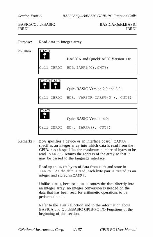
Section Four A BASICA/QuickBASIC GPIB-PC Function Calls
©National Instruments Corp. 4A-57 GPIB-PC User Manual
BASICA/QuickBASIC BASICA/QuickBASICIBRDI IBRDI
Purpose: Read data to integer array
Format:
BASICA and QuickBASIC Version 1.0:
Call IBRDI (BD%,IARR%(0),CNT%)
QuickBASIC Version 2.0 and 3.0:
Call IBRDI (BD%, VARPTR(IARR%(0)), CNT%)
QuickBASIC Version 4.0:
Call IBRDI (BD%, IARR%(), CNT%)
Remarks: BD% specifies a device or an interface board. IARR%specifies an integer array into which data is read from theGPIB. CNT% specifies the maximum number of bytes to beread. VARPTR returns the address of the array so that itmay be passed to the language interface.
Read up to CNT% bytes of data from BD% and store inIARR%. As the data is read, each byte pair is treated as aninteger and stored in IARR%.
Unlike IBRD, because IBRDI stores the data directly intoan integer array, no integer conversion is needed on thedata that has been read for arithmetic operations to beperformed on it.
Refer to the IBRD function and to the information aboutBASICA and QuickBASIC GPIB-PC I/O Functions at thebeginning of this section.
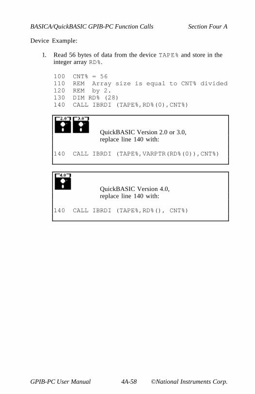
BASICA/QuickBASIC GPIB-PC Function Calls Section Four A
GPIB-PC User Manual 4A-58 ©National Instruments Corp.
Device Example:
1. Read 56 bytes of data from the device TAPE% and store in theinteger array RD%.
100 CNT% = 56110 REM Array size is equal to CNT% divided120 REM by 2.130 DIM RD% (28)140 CALL IBRDI (TAPE%,RD%(0),CNT%)
QuickBASIC Version 2.0 or 3.0,replace line 140 with:
140 CALL IBRDI (TAPE%,VARPTR(RD%(0)),CNT%)
QuickBASIC Version 4.0,replace line 140 with:
140 CALL IBRDI (TAPE%,RD%(), CNT%)
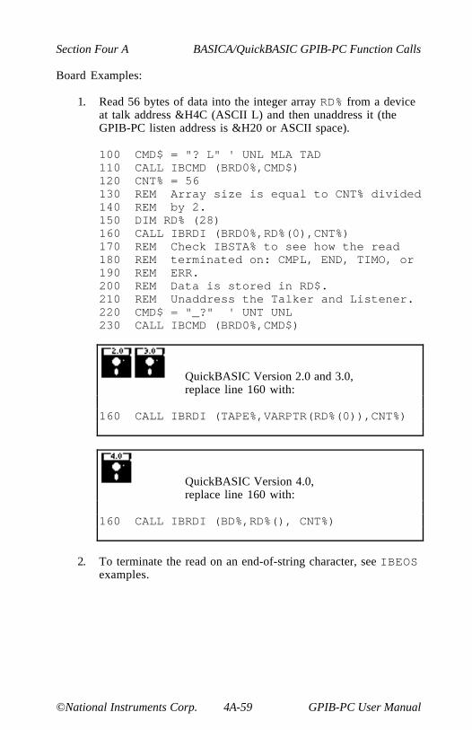
Section Four A BASICA/QuickBASIC GPIB-PC Function Calls
©National Instruments Corp. 4A-59 GPIB-PC User Manual
Board Examples:
1. Read 56 bytes of data into the integer array RD% from a deviceat talk address &H4C (ASCII L) and then unaddress it (theGPIB-PC listen address is &H20 or ASCII space).
100 CMD$ = "? L" ' UNL MLA TAD110 CALL IBCMD (BRD0%,CMD$)120 CNT% = 56130 REM Array size is equal to CNT% divided140 REM by 2.150 DIM RD% (28)160 CALL IBRDI (BRD0%,RD%(0),CNT%)170 REM Check IBSTA% to see how the read180 REM terminated on: CMPL, END, TIMO, or190 REM ERR.200 REM Data is stored in RD$.210 REM Unaddress the Talker and Listener.220 CMD$ = "_?" ' UNT UNL230 CALL IBCMD (BRD0%,CMD$)
QuickBASIC Version 2.0 and 3.0,replace line 160 with:
160 CALL IBRDI (TAPE%,VARPTR(RD%(0)),CNT%)
QuickBASIC Version 4.0,replace line 160 with:
160 CALL IBRDI (BD%,RD%(), CNT%)
2. To terminate the read on an end-of-string character, see IBEOSexamples.
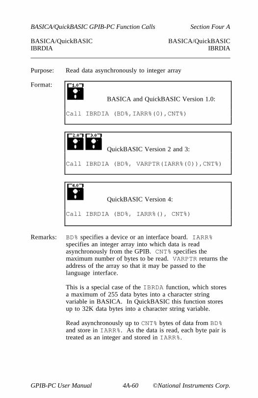
BASICA/QuickBASIC GPIB-PC Function Calls Section Four A
GPIB-PC User Manual 4A-60 ©National Instruments Corp.
BASICA/QuickBASIC BASICA/QuickBASICIBRDIA IBRDIA
Purpose: Read data asynchronously to integer array
Format:
BASICA and QuickBASIC Version 1.0:
Call IBRDIA (BD%,IARR%(0),CNT%)
QuickBASIC Version 2 and 3:
Call IBRDIA (BD%, VARPTR(IARR%(0)),CNT%)
QuickBASIC Version 4:
Call IBRDIA (BD%, IARR%(), CNT%)
Remarks: BD% specifies a device or an interface board. IARR%specifies an integer array into which data is readasynchronously from the GPIB. CNT% specifies themaximum number of bytes to be read. VARPTR returns theaddress of the array so that it may be passed to thelanguage interface.
This is a special case of the IBRDA function, which storesa maximum of 255 data bytes into a character stringvariable in BASICA. In QuickBASIC this function storesup to 32K data bytes into a character string variable.
Read asynchronously up to CNT% bytes of data from BD%and store in IARR%. As the data is read, each byte pair istreated as an integer and stored in IARR%.

Section Four A BASICA/QuickBASIC GPIB-PC Function Calls
©National Instruments Corp. 4A-61 GPIB-PC User Manual
Unlike IBRDA, IBRDIA stores the data directly into aninteger array. No integer conversion is needed on the datathat has been read for arithmetic operations to be performedon it.
NOTE: Do not pass dynamic arrays to the asynchronousfunctions IBRDIA and IBWRTIA, since the QuickBASICenvironment might move them around in memory during anI/O operation.
Refer to the IBRDA function and to the BASICA andQuickBASIC GPIB-PC I/O Functions at beginning of thissection.
Device Example:
1. Read 56 bytes of data into the integer array RD% from thedevice TAPE% while performing other processing.
100 REM Perform device read.110 CNT% = 56120 REM Array size is equal to CNT% divided130 REM by 2.140 DIM RD% (28)150 CALL IBRDIA (TAPE%,RD%(0),CNT%)160 MASK% = &H4100 ' TIMO CMPL170 REM Perform other processing here then180 REM wait for I/O completion or a190 REM timeout.200 CALL IBWAIT (TAPE%,MASK%)210 REM Check IBSTA% to see how the read220 REM terminated on: CMPL, END, TIMO, or230 REM ERR.240 REM If CMPL or ERR is not set,250 REM continue processing.260 IF (IBSTA% AND &H8100) = 0 GOTO 160270 REM Data is stored in RD%280 REM All unaddressing has been done.
QuickBASIC Version 2.0 or 3.0,replace line 150 with:
150 CALL IBRDIA (TAPE%,VARPTR(RD%(0)),CNT%)

BASICA/QuickBASIC GPIB-PC Function Calls Section Four A
GPIB-PC User Manual 4A-62 ©National Instruments Corp.
QuickBASIC Version 4.0,replace line 150 with:
150 CALL IBRDIA (TAPE%,RD%(),CNT%)
Board Examples:
1. Read 56 bytes of data into the integer array RD% from a deviceat talk address &H4C (ASCII L) and then unaddress it (theGPIB-PC listen address is &H20 or ASCII space).
100 REM Perform addressing in preparation110 REM for board read.120 CMD$ = "? L" ' UNL MLA TAD130 CALL IBCMD (BRD0%,CMD$)140 REM Perform board read.150 CNT% = 56160 REM Array size is equal to CNT% divided170 REM by 2.180 DIM RD% (28)190 CALL IBRDIA (BRD0%,RD%(0),CNT%)200 MASK% = &H4100 ' TIMO CMPL210 REM Perform other processing here then220 REM wait for I/O completion or a230 REM timeout.240 CALL IBWAIT (BRD0%,MASK%)250 REM Check IBSTA% to see how the read260 REM terminated on: CMPL, END, TIMO, or270 REM ERR.280 REM If CMPL or ERR are not set,290 REM continue processing.300 IF (IBSTA% AND &H8100) = 0 GOTO 200310 REM Data is stored in RD$.320 REM Unaddress the Talker and Listener.330 CMD$ = "_?" ' UNT UNL340 CALL IBCMD (BRD0%,CMD$)

Section Four A BASICA/QuickBASIC GPIB-PC Function Calls
©National Instruments Corp. 4A-63 GPIB-PC User Manual
QuickBASIC Version 2.0 or 3.0,replace line 190 with:
190 CALL IBRDIA (TAPE%,VARPTR(RD%(0)),CNT%)
QuickBASIC Version 4.0,replace line 190 with:
190 CALL IBRDIA (BD%,RD%(),CNT%)
2. To terminate the read on an end-of-string character, see IBEOSexamples.
BASICA/QuickBASIC GPIB-PC Function Calls Section Four A
GPIB-PC User Manual 4A-64 ©National Instruments Corp.
BASICA/QuickBASIC BASICA/QuickBASICIBRPP IBRPP
Purpose: Conduct a Parallel Poll
Format: CALL IBRPP (BD%,PPR%)
Remarks: BD% specifies a device or an interface board. PPR%identifies the variable where the parallel poll response byteis stored.
Device IBRPP Function:
When BD% specifies a device, all devices on its GPIB are polled inparallel using the access board of that GPIB. This is done by executingthe board IBRPP function with the appropriate access board specified.
Board IBRPP Function:
When BD% specifies a board, the IBRPP function causes the identifiedboard to conduct a parallel poll of previously configured devices bysending the IDY message (ATN and EOI both asserted) and reading theresponse from the GPIB data lines.
An ECIC error results if the GPIB-PC is not CIC. If the GPIB-PC isStandby Controller, it takes control and asserts ATN (becomes Active)prior to polling. It remains Active Controller afterward.
In the examples that follow, some of the GPIB commands and addressesare coded as printable ASCII characters. When the values to be sentover the GPIB correspond to printable ASCII characters, this is thesimplest means of specifying the values. Refer to Appendix A forconversions of numeric values to ASCII characters.
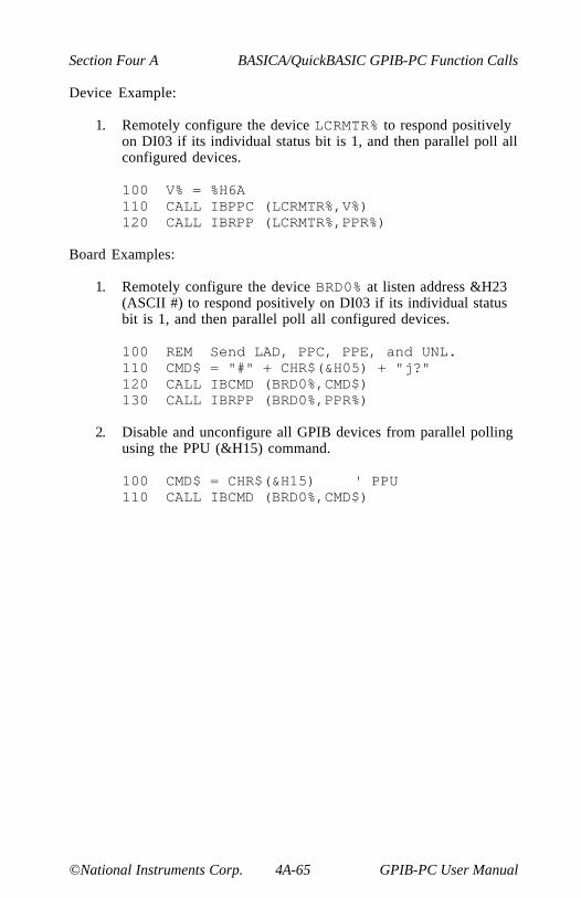
Section Four A BASICA/QuickBASIC GPIB-PC Function Calls
©National Instruments Corp. 4A-65 GPIB-PC User Manual
Device Example:
1. Remotely configure the device LCRMTR% to respond positivelyon DI03 if its individual status bit is 1, and then parallel poll allconfigured devices.
100 V% = %H6A110 CALL IBPPC (LCRMTR%,V%)120 CALL IBRPP (LCRMTR%,PPR%)
Board Examples:
1. Remotely configure the device BRD0% at listen address &H23(ASCII #) to respond positively on DI03 if its individual statusbit is 1, and then parallel poll all configured devices.
100 REM Send LAD, PPC, PPE, and UNL.110 CMD$ = "#" + CHR$(&H05) + "j?"120 CALL IBCMD (BRD0%,CMD$)130 CALL IBRPP (BRD0%,PPR%)
2. Disable and unconfigure all GPIB devices from parallel pollingusing the PPU (&H15) command.
100 CMD$ = CHR$(&H15) ' PPU110 CALL IBCMD (BRD0%,CMD$)

BASICA/QuickBASIC GPIB-PC Function Calls Section Four A
GPIB-PC User Manual 4A-66 ©National Instruments Corp.
BASICA/QuickBASIC BASICA/QuickBASICIBRSC IBRSC
Purpose: Request or release System Control
Format: CALL IBRSC (BD%,V%)
Remarks: BD% specifies an interface board. If V% is non-zero,functions requiring System Controller capability aresubsequently allowed. If V% is zero, functions requiringSystem Controller capability are disallowed.
The IBRSC function is used to enable or disable thecapability of the GPIB-PC to send the Interface Clear(IFC) and Remote Enable (REN) messages to GPIBdevices using the IBSIC and IBSRE functionsrespectively. The interface board must not be SystemController to respond to Interface Clear sent by anotherController.
In most applications, the GPIB-PC will always be theSystem Controller. In other applications, the GPIB-PC willnever be the System Controller. In either case, the IBRSCfunction is used only if the computer is not going to beSystem Controller for the duration of the programexecution. While the IEEE-488 standard does notspecifically allow schemes in which System Control can bepassed dynamically from one device to another, the IBRSCfunction would be used in such a scheme.
When IBRSC is called and an error does not occur, theprevious value of ist is stored in IBERR%.
Refer also to Table 2.1.
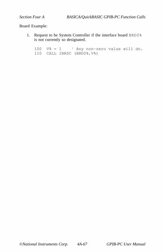
Section Four A BASICA/QuickBASIC GPIB-PC Function Calls
©National Instruments Corp. 4A-67 GPIB-PC User Manual
Board Example:
1. Request to be System Controller if the interface board BRD0%is not currently so designated.
100 V% = 1 ' Any non-zero value will do.110 CALL IBRSC (BRD0%,V%)
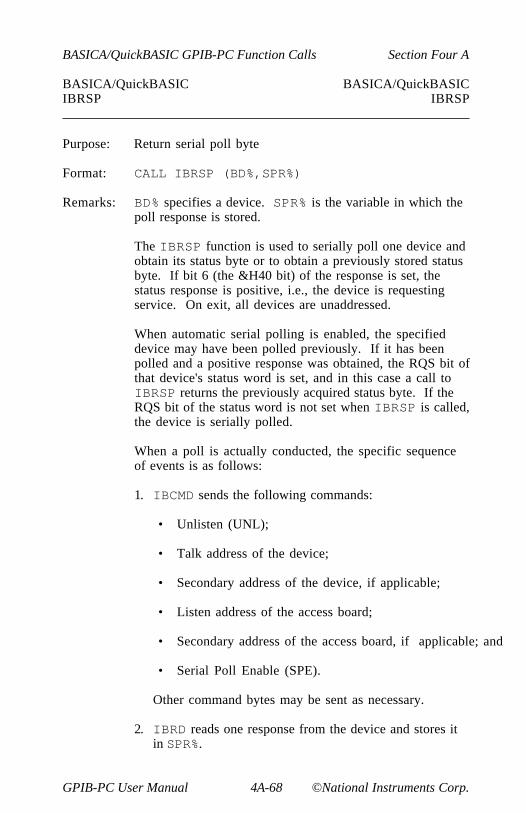
BASICA/QuickBASIC GPIB-PC Function Calls Section Four A
GPIB-PC User Manual 4A-68 ©National Instruments Corp.
BASICA/QuickBASIC BASICA/QuickBASICIBRSP IBRSP
Purpose: Return serial poll byte
Format: CALL IBRSP (BD%,SPR%)
Remarks: BD% specifies a device. SPR% is the variable in which thepoll response is stored.
The IBRSP function is used to serially poll one device andobtain its status byte or to obtain a previously stored statusbyte. If bit 6 (the &H40 bit) of the response is set, thestatus response is positive, i.e., the device is requestingservice. On exit, all devices are unaddressed.
When automatic serial polling is enabled, the specifieddevice may have been polled previously. If it has beenpolled and a positive response was obtained, the RQS bit ofthat device's status word is set, and in this case a call toIBRSP returns the previously acquired status byte. If theRQS bit of the status word is not set when IBRSP is called,the device is serially polled.
When a poll is actually conducted, the specific sequenceof events is as follows:
1. IBCMD sends the following commands:
• Unlisten (UNL);
• Talk address of the device;
• Secondary address of the device, if applicable;
• Listen address of the access board;
• Secondary address of the access board, if applicable; and
• Serial Poll Enable (SPE).
Other command bytes may be sent as necessary.
2. IBRD reads one response from the device and stores itin SPR%.

Section Four A BASICA/QuickBASIC GPIB-PC Function Calls
©National Instruments Corp. 4A-69 GPIB-PC User Manual
3. IBCMD sends the following commands:
• Untalk (UNT) and Unlisten (UNL); and
• Serial Poll Disable (SPD).
The interpretation of the response in SPR%, other than theRQS bit, is device-specific. For example, the polleddevice might set a particular bit in the response byte toindicatethat it has data to transfer, and another bit to indicate aneed for reprogramming. Consult the device documentationfor interpretation of the response byte.
Refer to IBCMD and IBRD for additional information.
Device Example:
1. Obtain the Serial Poll response (SPR) byte from the deviceTAPE%.
100 CALL IBRSP (TAPE%,SPR%)110 REM The application program would then120 REM analyze the response in SPR%.

BASICA/QuickBASIC GPIB-PC Function Calls Section Four A
GPIB-PC User Manual 4A-70 ©National Instruments Corp.
BASICA/QuickBASIC BASICA/QuickBASICIBRSV IBRSV
Purpose: Request service and/or set or change the serial poll statusbyte
Format: CALL IBRSV (BD%,V%)
Remarks: BD% specifies an interface board. V% specifies the responseor status byte the GPIB-PC provides when serially polledby another device that is the GPIB CIC. If bit 6 (the &H40bit) is set, the GPIB-PC additionally requests service fromthe Controller by asserting the GPIB SRQ line.
The IBRSV function is used to request service from theController using the Service Request (SRQ) signal and toprovide a system dependent status byte when the Controllerserially polls the GPIB-PC.
When IBRSV is called and an error does not occur, theprevious value of ist is stored in IBERR%.
Refer also to Table 2.1.
Board Examples:
1. Set the Serial Poll status byte to &H41, which simultaneouslyrequests service from an external CIC.
100 V% = &H41110 CALL IBRSV (BRD0%,V%)
2. Change the status byte as in Example 1, without requestingservice.
100 V% = &H01 ' New status byte value.110 CALL IBRSV (BRD0%,V%)

Section Four A BASICA/QuickBASIC GPIB-PC Function Calls
©National Instruments Corp. 4A-71 GPIB-PC User Manual
BASICA/QuickBASIC BASICA/QuickBASICIBSAD IBSAD
Purpose: Change or disable Secondary Address
Format: CALL IBSAD (BD%,V%)
Remarks: BD% specifies a device or an interface board. If V% is anumber between &H6O and &H7E, that number becomesthe secondary GPIB address device or interface board. IfV% is &H7F or zero, secondary addressing is disabled.IBSAD is needed only to alter the value from itsconfiguration setting.
The assignment made by this function remains in effectuntil IBSAD is called again, the IBONL or IBFINDfunction is called, or the system is rebooted.
When IBSAD is called and an error does not occur, theprevious value of ist is stored in IBERR%.
Device IBSAD Function:
When BD% specifies a device, the function enables or disables extendedGPIB addressing for the device. When secondary addressing is enabled,IBSAD records the secondary GPIB address of that device to be used insubsequent device I/O function calls.
Board IBSAD Function:
When BD% specifies an interface board, the IBSAD function enables ordisables extended GPIB addressing and, when enabled, assigns thesecondary address of the GPIB-PC.
Refer also to IBPAD, IBONL, and Table 2.1.
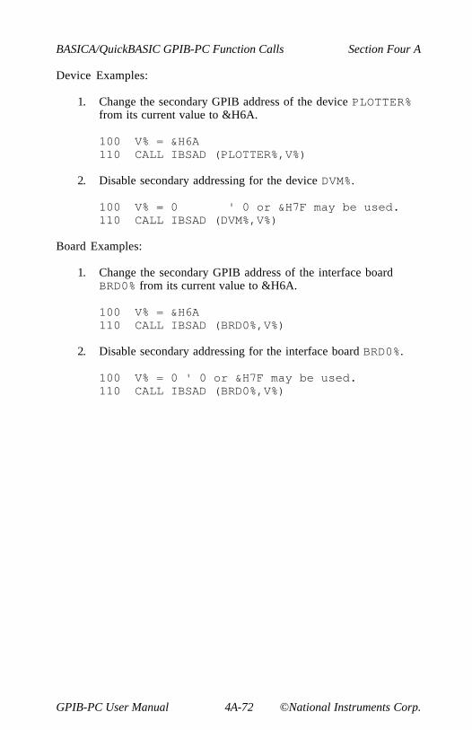
BASICA/QuickBASIC GPIB-PC Function Calls Section Four A
GPIB-PC User Manual 4A-72 ©National Instruments Corp.
Device Examples:
1. Change the secondary GPIB address of the device PLOTTER%from its current value to &H6A.
100 V% = &H6A110 CALL IBSAD (PLOTTER%,V%)
2. Disable secondary addressing for the device DVM%.
100 V% = 0 ' 0 or &H7F may be used.110 CALL IBSAD (DVM%,V%)
Board Examples:
1. Change the secondary GPIB address of the interface boardBRD0% from its current value to &H6A.
100 V% = &H6A110 CALL IBSAD (BRD0%,V%)
2. Disable secondary addressing for the interface board BRD0%.
100 V% = 0 ' 0 or &H7F may be used.110 CALL IBSAD (BRD0%,V%)
Section Four A BASICA/QuickBASIC GPIB-PC Function Calls
©National Instruments Corp. 4A-73 GPIB-PC User Manual
BASICA/QuickBASIC BASICA/QuickBASICIBSIC IBSIC
Purpose: Send interface clear for 100 microseconds
Format: CALL IBSIC (BD%)
Remarks: BD% specifies an interface board.
The IBSIC function causes the GPIB-PC to assert the IFCsignal for at least 100 microseconds, provided the GPIB-PChas System Controller capability. This action initializesthe GPIB and makes the interface board CIC and ActiveController with ATN asserted, and is generally used when abus fault condition is suspected.
The IFC signal resets only the GPIB interface functions ofbus devices and not the internal device functions. Devicefunctions are reset with the Device Clear (DCL) andSelected Device Clear (SDC) commands. To determinethe effect of these messages, consult the devicedocumentation.
The ESAC error occurs if the GPIB-PC does not haveSystem Controller capability.
Refer also to IBRSC.
Board Example:
1. Initialize the GPIB and become CIC and Active Controller atthe beginning of a program.
100 CALL IBSIC (BRD0%)

BASICA/QuickBASIC GPIB-PC Function Calls Section Four A
GPIB-PC User Manual 4A-74 ©National Instruments Corp.
BASICA/QuickBASIC BASICA/QuickBASICIBSRE IBSRE
Purpose: Set or clear the Remote Enable line
Format: CALL IBSRE (BD%,V%)
Remarks: BD% specifies an interface board. If V% is non-zero theRemote Enable (REN) signal is asserted. If V% is zero thesignal is unasserted.
The IBSRE function turns the REN signal on and off. RENis used by devices to select between local and remotemodes of operation. REN enables the remote mode. Adevice does not actually enter remote mode until itreceives its listen address.
The ESAC error occurs if the GPIB-PC is not SystemController.
When IBSRE is called and an error does not occur, theprevious value of V% is stored in IBERR%.
Refer also to IBRSC and Table 2.1.
Board Examples:
1. Place the device at listen address &H23 (ASCII #) in remotemode with local ability to return to local mode.
100 V% = 1 ' Any non-zero value will do.110 CALL IBSRE (BRD0%,V%)120 CMD$ = "#" ' LAD130 CALL IBCMD (BRD0%,CMD$)

Section Four A BASICA/QuickBASIC GPIB-PC Function Calls
©National Instruments Corp. 4A-75 GPIB-PC User Manual
2. To exclude the local ability of the device to return to localmode, send the Local Lockout (LLO or &H11) command orinclude it in the command string at 120 in Example 1.
100 CMD$ = CHR$(&H11)110 CALL IBCMD (BRD0%,CMD$)
or
100 CMD$ = "#" + CHR$(&H11)110 CALL IBCMD (BRD0%,CMD$)
3. Return all devices to local mode.
100 V% = 0 ' Set REN to false110 CALL IBSRE (BRD0%,V%)
BASICA/QuickBASIC GPIB-PC Function Calls Section Four A
GPIB-PC User Manual 4A-76 ©National Instruments Corp.
BASICA/QuickBASIC BASICA/QuickBASICIBSTOP IBSTOP
Purpose: Abort asynchronous operation
Format: CALL IBSTOP (BD%)
Remarks: BD% specifies a device or an interface board.
IBSTOP terminates any asynchronous read, write, orcommand operation in progress.
Device IBSTOP Function:
If BD% specifies a device, IBSTOP attempts to terminate any unfinishedasynchronous I/O operation to that device that had been started with adevice function for that device.
If the operation is aborted before completion, the ERR bit in the statusword is set and an EABO error is returned. No error indication results ifthe operation successfully completes before IBSTOP is called.
Board IBSTOP Function:
If BD% specifies a board, IBSTOP attempts to terminate any unfinishedasynchronous I/O operation that had been started with a board functionusing that board.
If the operation is aborted before completion, the ERR bit in the statusword is set and an EABO error is returned. No error indication results ifthe operation successfully completes before IBSTOP is called.
Device Example:
1. Stop any asynchronous operations associated with the deviceRDR%.
100 CALL IBSTOP (RDR%)
Section Four A BASICA/QuickBASIC GPIB-PC Function Calls
©National Instruments Corp. 4A-77 GPIB-PC User Manual
Board Example:
1. Stop any asynchronous operations associated with the interfaceboard BRD0%.
100 CALL IBSTOP (BRD0%)

BASICA/QuickBASIC GPIB-PC Function Calls Section Four A
GPIB-PC User Manual 4A-78 ©National Instruments Corp.
BASICA/QuickBASIC BASICA/QuickBASICIBTMO IBTMO
Purpose: Change or disable time limit
Format: CALL IBTMO (BD%,V%)
Remarks: BD% specifies a device or an interface board. V% is a codespecifying the time limit as follows:
Value Minimumof V% Timeout
0 disabled1 10 µsec2 30 µsec3 100 µsec4 300µsec5 1 msec6 3 msec7 10 msec8 30 msec9 100 msec
10 300 msec11 1 sec12 3 sec13 10 sec14 30 sec15 100 sec16 300 sec17 1000 sec
NOTE: If V% is zero, no limit is in effect.
IBTMO is needed only to alter the value from itsconfiguration setting.
The assignment made by this function remains in effectuntil IBTMO is called again, the IBONL or IBFINDfunction is called, or the system is rebooted.

Section Four A BASICA/QuickBASIC GPIB-PC Function Calls
©National Instruments Corp. 4A-79 GPIB-PC User Manual
The IBTMO function changes the length of time that thefollowing functions wait for the embedded I/O operation tofinish or for the specified event to occur before returningwith a timeout indication:
• IBCMD,
• IBRD,
• IBRDI,
• IBWRT, or
• IBWRTI.
The IBTMO function also changes the length of time thatdevice functions wait for commands to be accepted. If adevice does not accept commands within the time limit,the EBUS error will be returned.
When IBTMO is called and an error does not occur, theprevious value of ist is stored in IBERR%.
Device IBTMO Function:
When BD% specifies a device, the new time limit is used in subsequentdevice functions directed to that device.
Board IBTMO Function:
When BD% specifies a board, the new time limit is used in subsequentboard functions directed to that board.
Refer also to IBWAIT and to Table 2.1.
BASICA/QuickBASIC GPIB-PC Function Calls Section Four A
GPIB-PC User Manual 4A-80 ©National Instruments Corp.
Device Example:
1. Change the time limit for calls involving the device TAPE% toapproximately 300 msec.
100 V% = 10110 CALL IBTMO (TAPE%,V%)
Board Example:
1. Change the time limit for calls directed to the interface boardBRD0% to approximately 10 msec.
100 V% = 7110 CALL IBTMO (BRD0%,V%)

Section Four A BASICA/QuickBASIC GPIB-PC Function Calls
©National Instruments Corp. 4A-81 GPIB-PC User Manual
BASICA/QuickBASIC BASICA/QuickBASICIBTRAP IBTRAP
Purpose: Alter applications monitor trap and display modes
Format: CALL IBTRAP (MASK%,DISPLAY%)
Remarks: MASK% specifies a bit mask with the same bit assignmentsas the mask used with the function IBWAIT. Each MASK%bit is set, cleared to trap, or cleared not to trap,respectively, when the corresponding bit appears in thestatus word after a GPIB call. If all the bits are set, thenevery GPIB call is trapped.
MODE% determines when the recording and trapping occur.The valid values are:
1 Turn monitor off. No recording or trappingoccurs.
2 Turn record on. All calls are recorded butno trapping occurs.
3 Turn record and trap on. All calls arerecorded and the monitor is displayedwhenever a trap condition occurs.
If an error occurs during this call, the ERR bit of IBSTAwill be set and IBERR will be one of the following:
1 Applications monitor not installed.
2 Invalid monitor mode.
4 (EARG) IBTRAP not supported by installedhandler.
Otherwise, IBERR will contain the previous mask value.
Refer to Section Six for more information.

BASICA/QuickBASIC GPIB-PC Function Calls Section Four A
GPIB-PC User Manual 4A-82 ©National Instruments Corp.
Device Example:
1. Configure applications monitor to record and trap on SRQ orCMPL.
100 MASK% = &H1100 'SRQ or CMPL110 MODE% = 3 'Record and trap on120 CALL IBTRAP (MASK%, MODE%)
Section Four A BASICA/QuickBASIC GPIB-PC Function Calls
©National Instruments Corp. 4A-83 GPIB-PC User Manual
BASICA/QuickBASIC BASICA/QuickBASICIBTRG IBTRG
Purpose: Trigger selected device
Format: CALL IBTRG (BD%)
Remarks: BD% specifies a device.
The IBTRG function addresses and triggers the specifieddevice, then unaddresses all devices on the GPIB.
IBTRG calls the board IBCMD function to send thefollowing commands:
• Listen address of the device;
• Secondary address of the device, if applicable;
• Group Execute Trigger (GET); and
• Untalk (UNT) and Unlisten (UNL).
Other command bytes may be sent as necessary.
Refer to the IBCMD function for additional information.
Device Example:
1. Trigger the device ANALYZ%.
100 CALL IBTRG (ANALYZ%)
BASICA/QuickBASIC GPIB-PC Function Calls Section Four A
GPIB-PC User Manual 4A-84 ©National Instruments Corp.
BASICA/QuickBASIC BASICA/QuickBASICIBWAIT IBWAIT
Purpose: Wait for selected event
Format: CALL IBWAIT (BD%,MASK%)
Remarks: BD% specifies a device or an interface board. MASK% is abit mask with the same bit assignments as the status word,IBSTA%. Each MASK% bit is set or cleared to wait or notwait, respectively, for the corresponding event to occur.
The IBWAIT function is used to monitor the eventsselected in MASK% and to delay processing until any ofthem occur. These events and bit assignments are shown inTable 4A.4.
IBWAIT also updates all conditions of the status word,which may be read in the IBSTA% variable.
If MASK%=0 or MASK%=&H8000 (the ERR bit), the functionreturns immediately.
If the TIMO bit is 0, or the time limit is set to 0 with theIBTMO function, timeouts are disabled. Disabling timeoutsshould be done only when setting MASK%=0 or when it iscertain the selected event will occur; otherwise, theprocessor may wait indefinitely for the event to occur.

Section Four A BASICA/QuickBASIC GPIB-PC Function Calls
©National Instruments Corp. 4A-85 GPIB-PC User Manual
Table 4A.4 - Wait Mask Layout
Mnemonic Bit Hex DescriptionERR 15 8000 GPIB errorTIMO 14 4000 Time limit exceededEND 13 2000 GPIB-PC detected END or EOSSRQI 12 1000 SRQ onRQS 11 800 Device requesting serviceCMPL 8 100 I/O completedLOK 7 80 GPIB-PC is in lockout stateREM 6 40 GPIB-PC is in remote stateCIC 5 20 GPIB-PC is CICATN 4 10 Attention is assertedTACS 3 8 GPIB-PC is TalkerLACS 2 4 GPIB-PC is ListenerDTAS 1 2 GPIB-PC is in device trigger stateDCAS 0 1 GPIB-PC is in device clear state
Device IBWAIT Function:
When BD% specifies a device, only the ERR, TIMO, END, RQS, andCMPL bits of the wait mask and status word are applicable. On anIBWAIT for RQS, each time the GPIB SRQ line is asserted, the accessboard of the specified device serially polls all devices on its GPIB andsaves the responses, until the status byte returned by the device beingwaited for indicates that it was the device requesting service (bit &H40is set in the status byte). Note that an IBWAIT on RQS should only bedone on those devices that respond to serial polls. If the TIMO bit of themask is also set, IBWAIT returns if SRQ is not asserted within thedevice's timeout period. The serial polls are conducted with the boardfunctions IBCMD and IBRD.
Board IBWAIT Function:
When BD% specifies a board, all bits of the wait mask and status wordare applicable except RQS.
BASICA/QuickBASIC GPIB-PC Function Calls Section Four A
GPIB-PC User Manual 4A-86 ©National Instruments Corp.
Device Example:
1. Wait indefinitely for the device LOGGER% to request service.
100 MASK% = &H800 ' RQS110 CALL IBWAIT (LOGGER%,MASK%)
Board Examples:
1. Wait for a service request or a timeout.
100 MASK% = &H5000 ' TIMO SRQI110 CALL IBWAIT (BD%,MASK%)120 REM Check IBSTA% here to see which130 REM occurred.
2. Update the current status for IBSTA%.
100 MASK% = 0110 CALL IBWAIT (BD%,MASK%)
3. Wait indefinitely until control is passed from another CIC.
100 MASK% = &H20 ' CIC110 CALL IBWAIT (BD%,MASK%)
4. Wait indefinitely until addressed to talk or listen by anotherCIC.
100 MASK% = &H0C ' TACS LACS110 CALL IBWAIT (BD%,MASK%)
Section Four A BASICA/QuickBASIC GPIB-PC Function Calls
©National Instruments Corp. 4A-87 GPIB-PC User Manual
BASICA/QuickBASIC BASICA/QuickBASICIBWRT IBWRT
Purpose: Write data from string
Format: CALL IBWRT (BD%,WRT$)
Remarks: BD% specifies a device or an interface board. WRT$contains the data to be sent over the GPIB.
In BASICA, the IBWRT function writes from 1 to 255 bytesof data to a GPIB device. In QuickBASIC, the IBWRTfunction writes from 1 to 32K bytes of data to a GPIBdevice.
Device IBWRT Function:
When BD% specifies a device, the following board steps are performedautomatically to write to the device:
1. The IBCMD function is called to address the device to listenand the access board to talk.
2. The board IBWRT function is called to write the data to thedevice, as explained in the following discussion.
3. The IBCMD function is called to unaddress the access boardusing the Untalk command and all devices using the Unlistencommand.
Other command bytes may be sent as necessary.
When the device IBWRT function returns, IBSTA% holds the latestdevice status; IBCNT% is the actual number of data bytes written to thedevice; and IBERR% is the first error detected if the ERR bit in IBSTA%is set.
Board IBWRT Function:
When BD% specifies an interface board, the IBWRT function attempts towrite to a GPIB device that is assumed to already be properly initializedand addressed.
If the access board is CIC, the IBCMD function must be called prior toIBWRT to address the device to listen and the board to talk. Otherwise,the device on the GPIB that is the CIC must perform the addressing.

BASICA/QuickBASIC GPIB-PC Function Calls Section Four A
GPIB-PC User Manual 4A-88 ©National Instruments Corp.
If the access board is Active Controller, the board is first placed inStandby Controller state with ATN off and remains there after the writeoperation is completed. Otherwise, the write operation commencesimmediately.
An EADR error results if the board is CIC but has not been addressed totalk with the IBCMD function. An EABO error results if the board is notthe CIC and is not addressed to talk within the time limit. An EABOerror also results if the operation does not complete for whatever reasonwithin the time limit. An ENOL error occurs if there are no listeners onthe bus when the data bytes are sent.
Note that if you want to send an EOS character at the end of your datastring, you must place it there explicitly. See Device Example 2.
The board IBWRT operation terminates on any of the following events:
• All bytes are transferred;
• Error is detected;
• Time limit is exceeded; or
• Device Clear (DCL) or Selected Device Clear (SDC)command is received from another device which is the CIC.
After termination, IBCNT% contains the number of bytes written. Ashort count can occur on any event but the first.
Device Examples:
1. Write 10 instruction bytes to the device DVM%.
100 WRT$ = "F3R1X5P2G0"110 CALL IBWRT (DVM%,WRT$)
2. Write 5 instruction bytes terminated by a carriage return and alinefeed to the device PTR%. Linefeed is the device's EOScharacter.
100 WRT$ = "IP2X5" + CHR$(&H0D) + CHR$(&H0A)110 CALL IBWRT (PTR%,WRT$)

Section Four A BASICA/QuickBASIC GPIB-PC Function Calls
©National Instruments Corp. 4A-89 GPIB-PC User Manual
Board Example:
1. Write 10 instruction bytes to a device at listen address &H2F(ASCII /) and then unaddress it (the GPIB-PC talk address is&H40 or ASCII @).
100 REM Perform addressing.110 CMD$ = "?@/" ' UNL MTA LAD120 CALL IBCMD (BRD0%,CMD$)130 REM Perform board write.140 WRT$ = "F3R1X5P2G0"150 CALL IBWRT (BRD0%,WRT$)160 REM Unaddress the Talker and Listener.170 CMD$ = "_?" ' UNT UNL180 CALL IBCMD (BRD0%,CMD$)
BASICA/QuickBASIC GPIB-PC Function Calls Section Four A
GPIB-PC User Manual 4A-90 ©National Instruments Corp.
BASICA/QuickBASIC BASICA/QuickBASICIBWRTA IBWRTA
Purpose: Write data asynchronously from string
Format: CALL IBWRTA (BD%,WRT$)
Remarks: BD% specifies a device or an interface board. WRT$contains the data to be sent over the GPIB.
This is a special case of the IBWRTA function which inBASICA writes a maximum of 255 bytes from a characterstring to the GPIB. In QuickBASIC the function IBWRTAwrites a maximum of 32K bytes of data from a characterstring to the GPIB.
IBWRTA is used in place of IBWRT when the applicationprogram must perform other functions while processing theGPIB I/O operation. IBWRTA returns after starting the I/Ooperation. If the number of bytes to write is small and thebytes are received quickly by the GPIB device, theoperation may complete on the initial call. In this case,the CMPL bit will be set in IBSTA%. If the operation doesnot complete on the initial call, you should monitor theIBSTA% variable after subsequent calls (usually IBWAITcalls) to know that the I/O is completed. When CMPLbecomes set in IBSTA%, indicating that the I/O iscomplete, the number of bytes written is reported in theIBCNT% variable.
Device IBWRTA Function:
When BD% specifies a device, the following board steps are performedautomatically to write to the device:
1. The IBCMD function is called to address the device to listenand the assigned interface board to talk.
2. The board IBWRTA function is called to write the data to thedevice, as explained in the following discussion.
Other command bytes may be sent as necessary.
Section Four A BASICA/QuickBASIC GPIB-PC Function Calls
©National Instruments Corp. 4A-91 GPIB-PC User Manual
When the device IBWRTA function returns, IBSTA% holds the latestdevice status and IBERR% is the first error detected, if the ERR bit inIBSTA% is set. When the I/O finally completes and the CMPL bit is setin IBSTA%, the handler automatically unaddresses all devices.
Board IBWRTA Function:
When BD% specifies an interface board, the IBWRTA function attemptsto write to a GPIB device that is assumed to be already properlyinitialized and addressed.
If the board is CIC, the IBCMD function must be called prior to IBWRTAto address the device to listen and the board to talk. Otherwise, thedevice on the GPIB that is the CIC must perform the addressing.
If the board is Active Controller, the board is first placed in StandbyController state with ATN off and remains there after the write operationis completed. Otherwise, the write operation commences immediately.
An EADR error results if the board is CIC but has not been addressed totalk with the IBCMD function. An ENOL error occurs if there are nolisteners on the bus when the data bytes are sent.
Note that if you want to send an eos character at the end of your datastring, you must place it there explicitly.
Between the issuing of the IBWRTA call and the corresponding CMPL,other GPIB function calls to this device or to any other device with thesame access board, or any board calls to the access board itself, willreturn the error EOIP, with the following exceptions:
• IBSTOP - to cancel the asynchronous I/O;
• IBWAIT - to monitor other GPIB conditions; or
• IBONL - to cancel the I/O and reset the interface.
BASICA/QuickBASIC GPIB-PC Function Calls Section Four A
GPIB-PC User Manual 4A-92 ©National Instruments Corp.
Device Example:
1. Write 10 instruction bytes to the device DVM% while performingother processing.
100 WRT$ = "F3R1X5P2G0"110 CALL IBWRTA (DVM%,WRT$)120 MASK% = &H4100 'TIMO CMPL130 REM Perform other processing here then140 REM wait for I/O completion or a150 REM timeout.160 CALL IBWAIT (DVM%,MASK%)170 REM Check IBSTA% to see how the write180 REM terminated on: CMPL, END, TIMO, or190 REM ERR. If CMPL is not set,200 REM continue processing.210 IF (IBSTA% AND &H100) = 0 GOTO 130
Board Example:
1. Write 10 instruction bytes to a device at listen address &H2F(ASCII /), while testing for a high priority event to occur, andthen unaddress it (the GPIB-PC talk address is &H40 or ASCII@).
100 REM Perform addressing in preparation110 REM for board write.120 CMD$ = "?@/" ' UNL MTA LAD130 CALL IBCMD (BRD0%,CMD$)140 REM Perform board asynchronous write.150 WRT$ = "F3R1X5P2G0"160 CALL IBWRTA (BRD0%,WRT$)170 REM Perform other processing here then180 REM wait for I/O completion or a190 REM timeout.200 MASK% = &H4100 ' TIMO CMPL210 CALL IBWAIT (BRD0%,MASK%)220 REM Unaddress the Talker and Listener.230 CMD$ = "_?" ' UNT UNL240 CALL IBCMD (BRD0%,CMD$)
Section Four A BASICA/QuickBASIC GPIB-PC Function Calls
©National Instruments Corp. 4A-93 GPIB-PC User Manual
BASICA/QuickBASIC BASICA/QuickBASICIBWRTF IBWRTF
Purpose: Write data from file
Format: CALL IBWRTF (BD%,FLNAME$)
Remarks: BD% specifies a device or an interface board. FLNAME$indicates the filename from which the data is written to theGPIB. FLNAME$ may be up to 50 characters long,including a drive and path designation.
IBWRTF automatically opens the file. On exit, IBWRTFcloses the file.
An EFSO error results if it is not possible to open, seek,read, or close the file.
Device IBWRTF Function:
When BD% specifies a device, the device IBWRT function is called towrite to the device.
When the device IBWRTF function returns, IBSTA% holds the latestdevice status; IBCNT% is the actual number of data bytes written to thedevice, modulo 65,536; and IBERR% is the first error detected, if theERR bit in IBSTA% is set.
Board IBWRTF Function:
When BD% specifies an interface board, the board IBWRT function iscalled, which attempts to write to a GPIB device that is assumed to bealready properly initialized and addressed.
An EADR error results if the board is CIC but has not been addressed totalk with the IBCMD function. An EABO error results if the board is notthe CIC and is not addressed to talk within the time limit. An EABOerror also results if the operation does not complete for whatever reasonwithin the time limit. An ENOL error occurs if there are no listeners onthe bus when the data bytes are sent.

BASICA/QuickBASIC GPIB-PC Function Calls Section Four A
GPIB-PC User Manual 4A-94 ©National Instruments Corp.
The board IBWRTF operation terminates on any of the following events:
• All bytes sent;
• Error is detected;
• Time limit is exceeded; or
• Device Clear (DCL) or Selected Device Clear (SDC)command is received from another device which is the CIC.
After termination, IBCNT% contains the number of bytes written,modulo 65,536.
Device Example:
1. Write data to the device RDR% from the file Y.DAT on thecurrent disk drive.
100 FLNAME$ = "Y.DAT"110 CALL IBWRTF (RDR%,FLNAME$)
Board Example:
1. Write data to the device at listen address &H2C (ASCII ,) fromthe file Y.DAT on the current drive, and then unaddress theinterface board BRD0%.
100 REM Perform addressing in preparation110 REM for board write.120 CMD$ = "?@," ' UNL MTA LAD130 CALL IBCMD (BRD0%,CMD$)140 REM Perform board write.150 FLNAME$ = "Y.DAT"160 CALL IBWRTF (BRD0%,FLNAME$)170 REM Unaddress the Talker and Listener.180 CMD$ = "_?" ' UNT UNL190 CALL IBCMD (BRD0%,CMD$)

Section Four A BASICA/QuickBASIC GPIB-PC Function Calls
©National Instruments Corp. 4A-95 GPIB-PC User Manual
BASICA/QuickBASIC BASICA/QuickBASICIBWRTI IBWRTI
Purpose: Write data from integer array
Format:
BASICA and QuickBASIC Version 1.0:
Call IBWRTI (BD%,IARR%(0),CNT%)
QuickBASIC Version 2.0 and 3.0:
Call IBWRTI (BD%, VARPTR(IARR%(0)),CNT%)
QuickBASIC Version 4.0:
Call IBWRTI (BD%, IARR%(), CNT%)
Remarks: BD% specifies a device or an interface board. IARR% is aninteger array from which data is written to the GPIB. CNT%specifies the maximum number of bytes to be written.
Write CNT% bytes of data from IARR% to the GPIB. Thedata, stored as two-byte integers in IARR%, is sent in low-byte, high-byte order to the GPIB.
This is a special case of the IBWRT function, which writesa maximum of 255 bytes from a character string to theGPIB. This function is useful when those bytes are storedin integer format.
Refer to the IBWRT function and to the information aboutBASICA/QuickBASIC GPIB-PC I/O Functions at thebeginning of this section. Refer also to IBWRTIA.
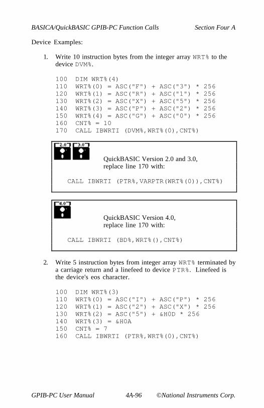
BASICA/QuickBASIC GPIB-PC Function Calls Section Four A
GPIB-PC User Manual 4A-96 ©National Instruments Corp.
Device Examples:
1. Write 10 instruction bytes from the integer array WRT% to thedevice DVM%.
100 DIM WRT%(4)110 WRT%(0) = ASC("F") + ASC("3") * 256120 WRT%(1) = ASC("R") + ASC("1") * 256130 WRT%(2) = ASC("X") + ASC("5") * 256140 WRT%(3) = ASC("P") + ASC("2") * 256150 WRT%(4) = ASC("G") + ASC("0") * 256160 CNT% = 10170 CALL IBWRTI (DVM%,WRT%(0),CNT%)
QuickBASIC Version 2.0 and 3.0,replace line 170 with:
CALL IBWRTI (PTR%,VARPTR(WRT%(0)),CNT%)
QuickBASIC Version 4.0,replace line 170 with:
CALL IBWRTI (BD%,WRT%(),CNT%)
2. Write 5 instruction bytes from integer array WRT% terminated bya carriage return and a linefeed to device PTR%. Linefeed isthe device's eos character.
100 DIM WRT%(3)110 WRT%(0) = ASC("I") + ASC("P") * 256120 WRT%(1) = ASC("2") + ASC("X") * 256130 WRT%(2) = ASC("5") + &H0D * 256140 WRT%(3) = &H0A150 CNT% = 7160 CALL IBWRTI (PTR%,WRT%(0),CNT%)

Section Four A BASICA/QuickBASIC GPIB-PC Function Calls
©National Instruments Corp. 4A-97 GPIB-PC User Manual
Board Example:
1. Write 10 instruction bytes from the integer array WRT% to adevice at listen address &H2F (ASCII /) and then unaddress it(the GPIB-PC talk address is &H40 or ASCII @).
100 REM Perform addressing.120 CMD$ = "?@/" ' UNL MTA LAD130 CALL IBCMD (BRD0%,CMD$)140 REM Perform board write.150 DIM WRT%(4)160 WRT%(0) = ASC("F") + ASC("3") * 256170 WRT%(1) = ASC("R") + ASC("1") * 256180 WRT%(2) = ASC("X") + ASC("5") * 256190 WRT%(3) = ASC("P") + ASC("2") * 256200 WRT%(4) = ASC("G") + ASC("0") * 256210 CNT% = 10220 CALL IBWRTI (BRD0%,WRT%(0),CNT%)230 REM Unaddress all Talkers and240 REM Listeners.250 CMD$ = "_?" ' UNT UNL260 CALL IBCMD (BRD0%,CMD$)
QuickBASIC Version 2.0 and 3.0,replace line 220 with:
CALL IBWRTI (PTR%,VARPTR(WRT%(0)),CNT%)
QuickBASIC Version 4.0,replace line 220 with:
CALL IBWRTI (BD%,WRT%(),CNT%)
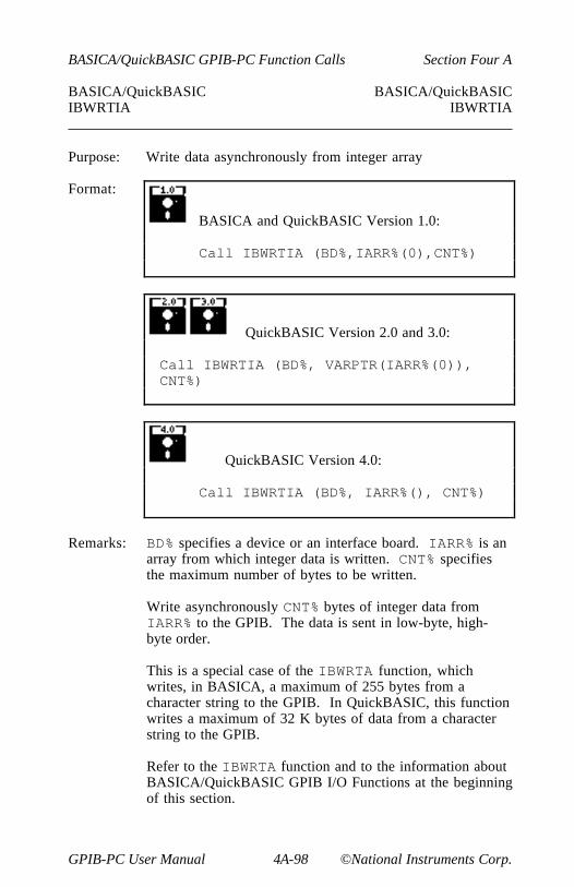
BASICA/QuickBASIC GPIB-PC Function Calls Section Four A
GPIB-PC User Manual 4A-98 ©National Instruments Corp.
BASICA/QuickBASIC BASICA/QuickBASICIBWRTIA IBWRTIA
Purpose: Write data asynchronously from integer array
Format:
BASICA and QuickBASIC Version 1.0:
Call IBWRTIA (BD%,IARR%(0),CNT%)
QuickBASIC Version 2.0 and 3.0:
Call IBWRTIA (BD%, VARPTR(IARR%(0)),CNT%)
QuickBASIC Version 4.0:
Call IBWRTIA (BD%, IARR%(), CNT%)
Remarks: BD% specifies a device or an interface board. IARR% is anarray from which integer data is written. CNT% specifiesthe maximum number of bytes to be written.
Write asynchronously CNT% bytes of integer data fromIARR% to the GPIB. The data is sent in low-byte, high-byte order.
This is a special case of the IBWRTA function, whichwrites, in BASICA, a maximum of 255 bytes from acharacter string to the GPIB. In QuickBASIC, this functionwrites a maximum of 32 K bytes of data from a characterstring to the GPIB.
Refer to the IBWRTA function and to the information aboutBASICA/QuickBASIC GPIB I/O Functions at the beginningof this section.
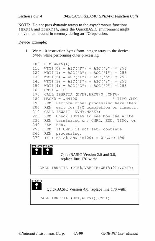
Section Four A BASICA/QuickBASIC GPIB-PC Function Calls
©National Instruments Corp. 4A-99 GPIB-PC User Manual
NOTE: Do not pass dynamic arrays to the asynchronous functionsIBRDIA and IBWRTIA, since the QuickBASIC environment mightmove them around in memory during an I/O operation.
Device Example:
1. Write 10 instruction bytes from integer array to the deviceDVM% while performing other processing.
100 DIM WRT%(4)110 WRT%(0) = ASC("F") + ASC("3") * 256120 WRT%(1) = ASC("R") + ASC("1") * 256130 WRT%(2) = ASC("X") + ASC("5") * 256140 WRT%(3) = ASC("P") + ASC("2") * 256150 WRT%(4) = ASC("G") + ASC("0") * 256160 CNT% = 10170 CALL IBWRTIA (DVM%,WRT%(0),CNT%)180 MASK% = &H4100 ' TIMO CMPL190 REM Perform other processing here then200 REM wait for I/O completion or timeout.210 CALL IBWAIT (DVM%,MASK%)220 REM Check IBSTA% to see how the write230 REM terminated on: CMPL, END, TIMO, or240 REM ERR.250 REM If CMPL is not set, continue260 REM processing.270 IF (IBSTA% AND &H100) = 0 GOTO 190
QuickBASIC Version 2.0 and 3.0,replace line 170 with:
CALL IBWRTIA (PTR%,VARPTR(WRT%(0)),CNT%)
QuickBASIC Version 4.0, replace line 170 with:
CALL IBWRTIA (BD%,WRT%(),CNT%)
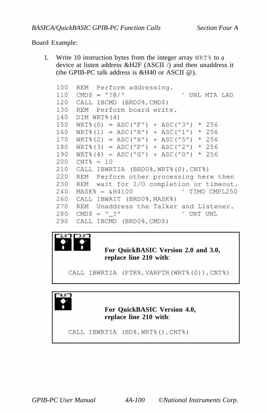
BASICA/QuickBASIC GPIB-PC Function Calls Section Four A
GPIB-PC User Manual 4A-100 ©National Instruments Corp.
Board Example:
1. Write 10 instruction bytes from the integer array WRT% to adevice at listen address &H2F (ASCII /) and then unaddress it(the GPIB-PC talk address is &H40 or ASCII @).
100 REM Perform addressing.110 CMD$ = "?@/" ' UNL MTA LAD120 CALL IBCMD (BRD0%,CMD$)130 REM Perform board write.140 DIM WRT%(4)150 WRT%(0) = ASC("F") + ASC("3") * 256160 WRT%(1) = ASC("R") + ASC("1") * 256170 WRT%(2) = ASC("X") + ASC("5") * 256180 WRT%(3) = ASC("P") + ASC("2") * 256190 WRT%(4) = ASC("G") + ASC("0") * 256200 CNT% = 10210 CALL IBWRTIA (BRD0%,WRT%(0),CNT%)220 REM Perform other processing here then230 REM wait for I/O completion or timeout.240 MASK% = &H4100 ' TIMO CMPL250260 CALL IBWAIT (BRD0%,MASK%)270 REM Unaddress the Talker and Listener.280 CMD$ = "_?" ' UNT UNL290 CALL IBCMD (BRD0%,CMD$)
For QuickBASIC Version 2.0 and 3.0,replace line 210 with:
CALL IBWRTIA (PTR%,VARPTR(WRT%(0)),CNT%)
For QuickBASIC Version 4.0,replace line 210 with:
CALL IBWRTIA (BD%,WRT%(),CNT%)

Section Four A BASICA/QuickBASIC GPIB-PC Function Calls
©National Instruments Corp. 4A-101 GPIB-PC User Manual
BASICA/QuickBASIC GPIB ProgrammingExamples
This section illustrates the programming steps that could be used toprogram a representative IEEE-488 instrument from your personalcomputer using the GPIB-PC handler functions. The applications arewritten in BASICA and QuickBASIC. The target instrument is a digitalvoltmeter (DVM). This instrument is otherwise unspecified (that is, it isnot a DVM manufactured by any particular manufacturer). The purposehere is to explain how to use the handler to execute certainprogramming and control sequences and not how to determine thosesequences.
Because the instructions that are sent to program a device as well as thedata that might be returned from the device are called devicedependent messages, the format and syntax of the messages used inthis example are unique to this device. Furthermore, the interfacemessages or bus commands that must be sent to devices will also vary,but to a lesser degree. The exact sequence of messages to program andto control a particular device are contained in its documentation.
For example, the following sequence of actions is assumed to benecessary to program this DVM to make and return measurements of ahigh frequency AC voltage signal in the autoranging mode:
1. Initialize the GPIB interface circuits of the DVM so that it canrespond to messages.
2. Place the DVM in remote programming mode and turn off frontpanel control.
3. Initialize the internal measurement circuits.
4. Program the DVM to the proper function (F3 for high frequencyAC volts), range (R7 for autoranging), and trigger source (T3for external or remote).
5. For each measurement:
a. Send the GET (Group Execute Trigger) command to triggerthe DVM.
b. Wait until the DVM asserts Service Request (SRQ) toindicate that the measurement is ready to be read.

BASICA/QuickBASIC GPIB-PC Function Calls Section Four A
GPIB-PC User Manual 4A-102 ©National Instruments Corp.
c. Serially poll the DVM to determine if the measured data isvalid (status byte = &HC0) or if a fault condition exists(the &H40 bit and another bit of the status byte, other than&H80, are set).
d. If the data is valid, read 16 bytes from the DVM.
6. End the session.
The example programs that follow are based on these assumptions:
• The GPIB-PC is the designated System Active Controller of theGPIB.
• There is no change to the GPIB-PC default hardware settings.
• The only changes made to the software parameters are thosenecessary to define the device DVM at primary address 3.
• There is only one GPIB-PC in use, which is designated GPIB0.
• Its primary listen and talk addresses are &H20 (ASCII spacecharacter) and &H40 (ASCII @ character), respectively.

Section Four A BASICA/QuickBASIC GPIB-PC Function Calls
©National Instruments Corp. 4A-103 GPIB-PC User Manual
BASICA Example Program - Device
BASICA - Using device function calls.
100 REM You must merge this code with DECL.BAS.105 REM110 REM Assign a unique identifier to device and120 REM store in variable DVM%.125 REM130 BDNAME$ = "DVM"140 CALL IBFIND (BDNAME$,DVM%)145 REM150 REM Check for error on IBFIND call.155 REM160 IF DVM% < 0 THEN GOTO 2000170 REM180 REM Clear the device.185 REM190 CALL IBCLR (DVM%)195 REM200 REM Check for an error on each GPIB call to210 REM be safe.215 REM220 IF IBSTA% < 0 THEN GOTO 3000230 REM240 REM Write the function, range, and trigger250 REM source instructions to the DVM.255 REM260 WRT$ = "F3R7T3" : CALL IBWRT (DVM%,WRT$)270 IF IBSTA% < 0 THEN GOTO 3000280 REM290 REM Trigger the device.295 REM300 CALL IBTRG (DVM%)310 IF IBSTA% < 0 THEN GOTO 3000320 REM330 REM Wait for the DVM to set RQS or for a340 REM timeout; if the current time limit is too350 REM short, use IBTMO to change it.355 REM360 MASK% = &H4800 : CALL IBWAIT (DVM%,MASK%)370 IF (IBSTA% AND &HC000) <> 0 THEN GOTO 3000380 REM390 REM Since neither a timeout nor an error400 REM occurred, IBWAIT must have returned on410 REM RQS. Next, serial poll the device.
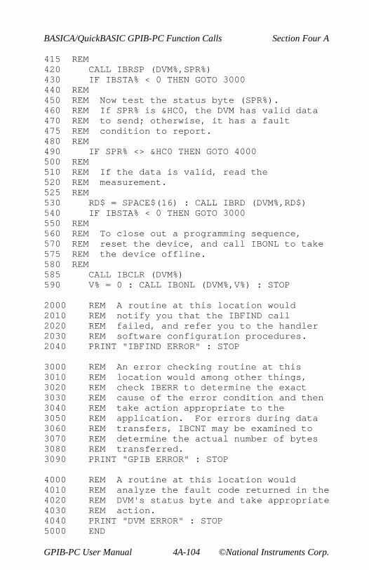
BASICA/QuickBASIC GPIB-PC Function Calls Section Four A
GPIB-PC User Manual 4A-104 ©National Instruments Corp.
415 REM420 CALL IBRSP (DVM%,SPR%)430 IF IBSTA% < 0 THEN GOTO 3000440 REM450 REM Now test the status byte (SPR%).460 REM If SPR% is &HC0, the DVM has valid data470 REM to send; otherwise, it has a fault475 REM condition to report.480 REM490 IF SPR% <> &HC0 THEN GOTO 4000500 REM510 REM If the data is valid, read the520 REM measurement.525 REM530 RD$ = SPACE$(16) : CALL IBRD (DVM%,RD$)540 IF IBSTA% < 0 THEN GOTO 3000550 REM560 REM To close out a programming sequence,570 REM reset the device, and call IBONL to take575 REM the device offline.580 REM585 CALL IBCLR (DVM%)590 V% = 0 : CALL IBONL (DVM%,V%) : STOP
2000 REM A routine at this location would2010 REM notify you that the IBFIND call2020 REM failed, and refer you to the handler2030 REM software configuration procedures.2040 PRINT "IBFIND ERROR" : STOP
3000 REM An error checking routine at this3010 REM location would among other things,3020 REM check IBERR to determine the exact3030 REM cause of the error condition and then3040 REM take action appropriate to the3050 REM application. For errors during data3060 REM transfers, IBCNT may be examined to3070 REM determine the actual number of bytes3080 REM transferred.3090 PRINT "GPIB ERROR" : STOP
4000 REM A routine at this location would4010 REM analyze the fault code returned in the4020 REM DVM's status byte and take appropriate4030 REM action.4040 PRINT "DVM ERROR" : STOP5000 END

Section Four A BASICA/QuickBASIC GPIB-PC Function Calls
©National Instruments Corp. 4A-105 GPIB-PC User Manual
BASICA Example Program - Board
BASICA - Using board function calls
100 REM You must merge this code with DECL.BAS.105 REM110 REM Assign a unique identifier to board 0 and120 REM store in the variable BRD0%.125 REM130 BDNAME$ = "GPIB0"140 CALL IBFIND (BDNAME$,BRD0%)145 REM150 REM Check for error on IBFIND call.153 REM155 IF BRD0% < 0 THEN GOTO 2000160 REM165 REM Send the Interface Clear (IFC) message to170 REM all devices.175 REM180 CALL IBSIC (BRD0%)190 REM200 REM Check for an error on each GPIB call.215 REM220 IF IBSTA% < 0 THEN GOTO 3000230 REM240 REM Turn on the Remote Enable (REN) signal.245 REM250 V% = 1 : CALL IBSRE (BRD0%,V%)260 IF IBSTA% < 0 THEN GOTO 3000270 REM280 REM Inhibit front panel control with the290 REM Local Lockout (LLO) command, place the300 REM DVM in remote mode by addressing it to310 REM listen, send the Device Clear (DCL)320 REM message to clear internal device330 REM functions, and address the GPIB0 to talk.345 REM350 CMD$ = CHR$(&H11)+ "#" +CHR$(&H14)+ "@"360 CALL IBCMD (BRD0%,CMD$)370 IF IBSTA% < 0 THEN GOTO 3000380 REM390 REM Write the function, range, and trigger400 REM source instructions to the DVM.405 REM410 WRT$ = "F3R7T3" : CALL IBWRT (BRD0%,WRT$)420 IF IBSTA% < 0 THEN GOTO 3000
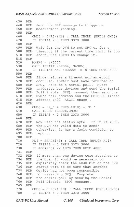
BASICA/QuickBASIC GPIB-PC Function Calls Section Four A
GPIB-PC User Manual 4A-106 ©National Instruments Corp.
430 REM440 REM Send the GET message to trigger a450 REM measurement reading.455 REM460 CMD$ = CHR$(&H8) : CALL IBCMD (BRD0%,CMD$)470 IF IBSTA% < 0 THEN GOTO 3000480 REM490 REM Wait for the DVM to set SRQ or for a500 REM timeout; if the current time limit is too510 REM short, use IBTMO to change it.515 REM520 MASK% = &H5000530 CALL IBWAIT (BRD0%, MASK%)540 IF (IBSTA% AND &HC000) <> 0 THEN GOTO 3000550 REM560 REM Since neither a timeout nor an error570 REM occurred, IBWAIT must have returned on580 REM SRQ. Next do a serial poll. First590 REM unaddress bus devices and send the Serial600 REM Poll Enable (SPE) command, then send the610 REM DVM's talk address and the GPIB-PC listen615 REM address &H20 (ASCII space).620 REM630 CMD$ = "?_" + CHR$(&H18) + "C "640 CALL IBCMD (BRD0%,CMD$)650 IF IBSTA% < 0 THEN GOTO 3000660 REM670 REM Now read the status byte. If it is &HC0,680 REM the DVM has valid data to send;690 REM otherwise, it has a fault condition to695 REM report.700 REM710 RD$ = SPACE$(1) : CALL IBRD (BRD0%,RD$)720 IF IBSTA% < 0 THEN GOTO 3000730 IF ASC(RD$) <> &HC0 THEN GOTO 4000731 REM732 REM If more than one device were attached to734 REM the bus, it would be necessary to735 REM explicitly check the &H40 bit of the DVM736 REM status word to be sure that another738 REM device had not been responsible740 REM for asserting SRQ. Complete750 REM the serial poll by sending the Serial760 REM Poll Disable (SPD) message.765 REM770 CMD$ = CHR$(&H19) : CALL IBCMD (BRD0%,CMD$)780 IF IBSTA% < 0 THEN GOTO 3000
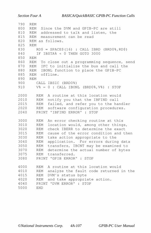
Section Four A BASICA/QuickBASIC GPIB-PC Function Calls
©National Instruments Corp. 4A-107 GPIB-PC User Manual
790 REM800 REM Since the DVM and GPIB-PC are still810 REM addressed to talk and listen, the815 REM measurement can be read820 REM as follows.825 REM830 RD$ = SPACE$(16) : CALL IBRD (BRD0%,RD$)840 IF IBSTA% < 0 THEN GOTO 3000850 REM860 REM To close out a programming sequence, send870 REM IFC to initialize the bus and call the880 REM IBONL function to place the GPIB-PC885 REM offline.890 REM900 CALL IBSIC (BRD0%)910 V% = 0 : CALL IBONL (BRD0%,V%) : STOP
2000 REM A routine at this location would2010 REM notify you that the IBFIND call2015 REM failed, and refer you to the handler2020 REM software configuration procedures.2040 PRINT "IBFIND ERROR" : STOP
3000 REM An error checking routine at this3010 REM location would, among other things,3020 REM check IBERR to determine the exact3015 REM cause of the error condition and then3030 REM take action appropriate to the3040 REM application. For errors during data3050 REM transfers, IBCNT may be examined to3070 REM determine the actual number of bytes3075 REM transferred.3080 PRINT "GPIB ERROR" : STOP
4000 REM A routine at this location would4010 REM analyze the fault code returned in the4015 REM DVM's status byte4020 REM and take appropriate action.4040 PRINT "DVM ERROR" : STOP5000 END

BASICA/QuickBASIC GPIB-PC Function Calls Section Four A
GPIB-PC User Manual 4A-108 ©National Instruments Corp.
QuickBASIC Example Program - Device
QuickBASIC - Using device function calls.
COMMON SHARED IBSTA%, IBERR%, IBCNT%REM Assign a unique identifier to deviceREM and store in variable DVM%.REMBDNAME$ = "DVM"CALL IBFIND (BDNAME$,DVM%)
REMREM Check for error on IBFIND call.REMIF DVM% < 0 THEN GOSUB FIND-ERROR:
REMREM Clear the device.REMCALL IBCLR (DVM%)
REMREM Check for an error on each GPIB callREM to be safe.REMIF IBSTA% < 0 THEN GOSUB GPIB-ERROR:
REMREM Write the function, range, and triggerREM source instructions to the DVM.REMWRT$ = "F3R7T3" : CALL IBWRT (DVM%,WRT$)IF IBSTA% < 0 THEN GOSUB GPIB-ERROR:
REMREM Trigger the device.REMCALL IBTRG (DVM%)IF IBSTA% < 0 THEN GOSUB GPIB-ERROR:
REMREM Wait for the DVM to set RQS or for aREM timeout; if the current time limitREM is too short, use IBTMO to change it.REMMASK% = &H4800 : CALL IBWAIT (DVM%,MASK%)IF (IBSTA% AND &HC000) <> 0 THEN GOSUB GPIB-ERROR:
REMREM Since neither a timeout nor an errorREM occurred, IBWAIT must have returnedREM on RQS. Next, serial poll the device.REM

Section Four A BASICA/QuickBASIC GPIB-PC Function Calls
©National Instruments Corp. 4A-109 GPIB-PC User Manual
CALL IBRSP (DVM%,SPR%)IF IBSTA% < 0 THEN GOSUB GPIB-ERROR:
REMREM Now test the status byte (SPR%).REM If SPR% is &HC0, the DVM has validREM data to send; otherwise, it has aREM fault condition to report.REMIF SPR% <> &HC0 THEN GOSUB DEVICE-ERROR:
REMREM If the data is valid, read theREM measurement.REMRD$ = SPACE$(16) : CALL IBRD (DVM%,RD$)IF IBSTA% < 0 THEN GOSUB GPIB-ERROR:
REMREM To close out a programming sequence,REM reset the device, and call IBONLREM to place the device offline.REMCALL IBCLR (DVM%)V% = 0CALL IBONL (DVM%,V%) : STOPEND
IBFIND-ERROR:REM A routine at this location would notifyREM you that the IBFIND call failed, andREM refer you to the handler softwareREM configuration procedures.PRINT "IBFIND ERROR" : STOP
GPIB-ERROR:REM An error checking routine at thisREM location would, among other things,REM check IBERR to determine the exact cause ofREM the error condition and then take actionREM appropriate to the application.REM For errors during data transfers,REM IBCNT may be examined to determine the actualREM number of bytes transferred.PRINT "GPIB ERROR" : STOP

BASICA/QuickBASIC GPIB-PC Function Calls Section Four A
GPIB-PC User Manual 4A-110 ©National Instruments Corp.
DEVICE-ERROR:REM A routine at this location would analyzeREM the fault code returned in the DVM's statusREM byte and take appropriate action.PRINT "DVM ERROR" : STOPEND

Section Four A BASICA/QuickBASIC GPIB-PC Function Calls
©National Instruments Corp. 4A-111 GPIB-PC User Manual
QuickBASIC Example Program - Board
QuickBASIC - Using board function calls.
COMMON SHARED IBSTA%, IBERR%, IBCNT%REMREM Assign a unique identified to board 0 andREM store in variable BRD0%.REMBDNAME$ = "GPIB0"CALL IBFIND (BDNAME$,BRD0%)
REMREM Check for error on IBFIND call.REMIF BRD0% < 0 THEN GOSUB FIND-ERROR:
REMREM Send the Interface Clear (IFC) message toREM all devices.REMCALL IBSIC (BRD0%)
REMREM Check for an error on each GPIB callREM to be safe.REMIF IBSTA% , 0 THEN GOSUB GPIB-ERROR:
REMREM Turn on the Remote Enable (REN) signal.REMV% = 1 : CALL IBSRE (BRD0%,V%)IF IBSTA% < 0 THEN GOSUB GPIB-ERROR:
REMREM Inhibit fron panel control with theREM Local Lockout (LLO) command, place theREM DVM in remote by addressing it to listen,REM send the Device Clear (DCL) message to clearREM internal device functions, and address theREM GPIB-PC to talk.REMCMD$ = CHR$(&H11)+"#" +CHR$(&H14)+"@"CALL IBCMD (BRD0%,CMD$)IF IBSTA% < 0 THEN GOSUB GPIB-ERROR:
REMREM Write the function, range, and triggerREM source instructions to the DVMREMWRT$ = "F3R7T3" : CALL IBWRT (BRD0%,WRT$)

BASICA/QuickBASIC GPIB-PC Function Calls Section Four A
GPIB-PC User Manual 4A-112 ©National Instruments Corp.
IF IBSTA% < 0 THEN GOSUB GPIB-ERROR:REMREM Send the GET message to trigger aREM measurement reading.REMCMD$ = CHR$(&H8) : CALL IBCMD (BRD0%,CMD$)IF IBSTA% < 0 THEN GOSUB GPIB-ERROR:
REMREM Wait for the DVM to set SRQ or for aREM timeout; if the current time limitREM is too short, use IBTMO to change it.REMMASK% = &H5000CALL IBWAIT (BRD0%,MASK%)IF (IBSTA% AND &HC000) <> 0 THEN GOSUB GPIB-
ERROR:REMREM Since neither a timeout nor an errorREM occurred, IBWAIT must have returnedREM on SRQ. Next do a serial poll.REM First unaddress bus devices and sendREM the Serial Poll Enable (SPE) command,REM then send the DVM's talk address andREM the GPIB0 listen address &H20 (ASCIIREM space).REMCMD$ = "?_" + CHR$(&H18) + "C"CALL IBCMD (BRD0%,CMD$)IF IBSTA% < 0 THEN GOSUB GPIB-ERROR:
REMREM Now read the status byte. If it isREM &HC0, the DVM has a valid data to send;REM otherwise, it has a fault conditionREM to report.REMRD$ = SPACE$(1) : CALL IBRD (BRD0%,RD$)IF IBSTA% < 0 THEN GOSUB GPIB-ERROR:IF ASC(RD$) <> &HC0 THEN GOSUB DEVICE-ERROR:
REMREM If more than one device were attached toREM the bus, it would be necessary to explicitlyREM check the &HC0 bit if the DVM statusREM word to be sure that another device hadREM not been responsible for asserting SRQ.REM Complete the serial poll by sendingREM the Serial Poll Disable (SPD) message.REM

Section Four A BASICA/QuickBASIC GPIB-PC Function Calls
©National Instruments Corp. 4A-113 GPIB-PC User Manual
CMD$ = CHR$(&H19) : CALL IBCMD (BRD0%,CMD$)IF IBSTA% < 0 THEN GOSUB GPIB-ERROR:
REMREM Since the DVM and GPIB-PC areREM still addressed to talk and listen,REM the measurement can be read as follows.REMRD$ = SPACE$(16) : CALL IBRD (BRD0%,RD$)IF IBSTA% < 0 THEN GOSUB GPIB-ERROR:
REMREM To close out a programming sequence,REM send IFC to initialize the bus andREM call the IBONL function to place theREM GPIB-PC offline.REMCALL IBSIC (BRD0%)V% = 0 : CALL IBONL (BRD0%,V%) : STOPEND
FIND-ERROR:REM A routine at this location wouldREM notify you that the IBFIND callREM failed, and refer you to theREM handler, software configurationREM procedures.PRINT "IBFIND ERROR" : STOP
GPIB-ERROR:REM An error checking routine at thisREM location would, among other things,REM check IBERR to determine the exactREM cause of the error condition andREM then take action appropriate toREM the application. For errors duringREM data transfers, IBCNT may beREM examined to determine the actualREM number of bytes transferred.PRINT "GPIB ERROR" : STOP
DEVICE-ERROR:REM A routine at this location wouldREM analyze the fault code returned inREM the DVM's status byte and takeREM appropriate action.PRINT "DVM ERROR" : STOPEND

©National Instruments Corp. 5-1 GPIB-PC User Manual
Section Five - IBIC
The IEEE-488 Bus Interactive Control program (IBIC) allows you tocontrol and communicate with the GPIB through functions you enter atthe keyboard. This feature helps you establish communication with thedevice, troubleshoot problems, and develop the application.
IBIC functions include most of the GPIB-PC functions described inSections Three and Four, plus auxiliary functions used only by IBIC.
In IBIC, the user can send data and GPIB commands to a device fromthe keyboard and display data on the screen received from a device.After each GPIB-PC function is executed, the numeric value andmnemonic representation of the status word IBSTA is displayed. Thebyte count IBCNT and error code IBERR are also shown whenappropriate.
This interactive method of data input and data/status output is designedto help you learn how to use the GPIB-PC functions to program yourdevice. Once you develop a sequence of steps that works successfullyfor your system, you can easily incorporate the sequence into anapplication program using the appropriate language and syntaxdescribed in Section Four.

IBIC Section Five
GPIB-PC User Manual 5-2 ©National Instruments Corp.
Running IBIC
The IBIC program, IBIC.EXE, is an executable file that was copiedfrom the distribution diskette to a subdirectory called GPIB-PC whenyou ran IBSTART at installation.
To run IBIC, change directory to C:\GPIB-PC and enter:
C:\GPIB-PC> ibic
National InstrumentsInterface Bus Interactive Control Program (IBIC)Copyright (c) 1984 National Instru ments, Inc.All Rights Reserved
Type "help" for help.
Use IBFIND to initially open a boa rd or device.Use SET to select an already opene d board or device.
Messages will appear on the screen that give you information about theHELP, IBFIND, and SET commands.
The first input prompt to IBIC is a colon (:).
NOTE: In using IBIC, the four most important functions are the HELP,IBFIND, IBWRT, and IBRD commands.

Section Five IBIC
©National Instruments Corp. 5-3 GPIB-PC User Manual
Using HELP
The HELP function gives on-line information about IBIC and thefunctions available within the environment. This facility provides aquick reference for checking the syntax and function of the GPIB call.
Using IBFIND
To execute any GPIB function, you must first use IBFIND to open thedevice or board you wish to use. When the device or board is opened,the symbolic name of that device or board is added to the prompt.
The following examples show IBFIND opening dev1 (Example 1) andgpib0 (Example 2). The user's inputs are italicized.
Example 1:
:ibfind dev1
dev1:
Example 2:
:ibfind gpib0
gpib0:
The name used with the IBFIND function must be a valid symbolicname known by the handler. Both dev1 and gpib0 are default namesfound in the handler. IBIC makes no distinction between uppercaseand lowercase.

IBIC Section Five
GPIB-PC User Manual 5-4 ©National Instruments Corp.
Using IBWRT
The IBWRT command sends data from one GPIB device to another. Forexample, to send a data string from the computer to a device calleddev1, the following command would suffice:
Example:
dev1: [0100] (cmpl)count: 6
ibwrt "F3R5T1"
This command sends the string "F3R5T1" to device called dev1. Thereturned Status Word [0100] indicates a successful I/O completion,while the Byte Count indicates that all six characters were sent fromthe computer and received by the device.
Using IBRD
The IBRD command causes a GPIB device to receive data from anotherGPIB device. The following example illustrates the use of the IBRDfunction.
Example:
N D C V ( 0 0 0. 0 0 4 7 E + 0• •
dev1:[2100] (end cmpl)count: 184E 44 43 56 28 30 30 302E 30 30 34 37 45 2B 300D 0A
ibrd 20
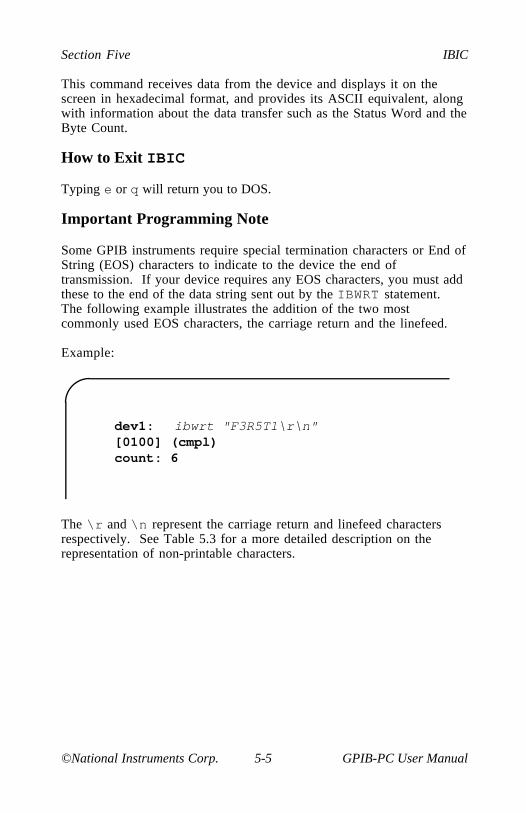
Section Five IBIC
©National Instruments Corp. 5-5 GPIB-PC User Manual
This command receives data from the device and displays it on thescreen in hexadecimal format, and provides its ASCII equivalent, alongwith information about the data transfer such as the Status Word and theByte Count.
How to Exit IBIC
Typing e or q will return you to DOS.
Important Programming Note
Some GPIB instruments require special termination characters or End ofString (EOS) characters to indicate to the device the end oftransmission. If your device requires any EOS characters, you must addthese to the end of the data string sent out by the IBWRT statement.The following example illustrates the addition of the two mostcommonly used EOS characters, the carriage return and the linefeed.
Example:
dev1:[0100] (cmpl)count: 6
ibwrt "F3R5T1\r\n"
The \r and \n represent the carriage return and linefeed charactersrespectively. See Table 5.3 for a more detailed description on therepresentation of non-printable characters.

IBIC Section Five
GPIB-PC User Manual 5-6 ©National Instruments Corp.
Using SET
Use IBFIND to open each device or board. Once the device or board isopened, use the auxiliary function SET to select which opened deviceor board to access. SET changes the prompt to the new symbolic name.
Example:
dev1:
plotter:
set plotter
This example assumes that IBCONF was used to give a device thename plotter.
The following example summarizes the use of IBFIND and SET in atypical program.
Example:
dev1:
plotter: ibwrt "F3T7G0"[0100] (cmpl)count: 6
plotter: set dev1
dev1: ibwrt "X7Y39G0"[0100] (cmpl)count: 7
dev1:
ibfind plotter
: ibfind dev1

Section Five IBIC
©National Instruments Corp. 5-7 GPIB-PC User Manual
IBIC Functions and Syntax
IBIC displays the following information about each function callimmediately after that call:
• IBRD and IBRDA data messages are displayed on the screen inhex and ASCII formats.
• The global variables IBSTA, IBCNT, and IBERR are displayedon the screen.
IBIC and programming languages of Section Four differ in the syntaxof the function call. These differences are shown in Table 5.1. Themain differences are that IBWRT, IBWRTA, IBCMD, and IBCMDAmessages are entered as strings from the keyboard.
The BD unit descriptor is not explicitly a part of IBIC function syntax.Before using any device or board, first call IBFIND to open that unitand to pass the unit descriptor to IBIC. The screen prompt identifieswhich of these opened units IBIC will use in subsequent calls. Use theSET function to change from one of these units to another.
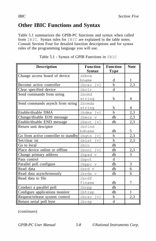
IBIC Section Five
GPIB-PC User Manual 5-8 ©National Instruments Corp.
Other IBIC Functions and Syntax
Table 5.1 summarizes the GPIB-PC functions and syntax when calledfrom IBIC. Syntax rules for IBIC are explained in the table notes.Consult Section Four for detailed function descriptions and for syntaxrules of the programming language you will use.
Table 5.1 - Syntax of GPIB Functions in IBIC
Description Function Function NoteSyntax Type
Change access board of device ibbnabname d 1
Become active controller ibcac [v] b 2,3Clear specified device ibclr dSend commands from string ibcmd
string b 4Send commands asynch from string ibcmda
string b 4Enable/disable DMA ibdma [v] b 2,3Change/disable EOS message ibeos v db 2,3Enable/disable END message ibeot [v] db 2,3Return unit desciptor ibfind
bdname db 5Go from active controller to standby ibgts [v] b 2,3Set/clear ist ibist [v] b 2,3Go to local iblo dbPlace device online or offline ibonl [v] db 2,3Change primary address ibpad v db 3Pass control ibpct dParallel poll configure ibppc v db 3Read data ibrd v db 6Read data asynchronously ibrda v db 6Read data to file ibrdf
flname db 7Conduct a parallel poll ibrpp dbConfigure applications monitor ibtrap db 1Request/release system control ibrsc [v] b 2,3Return serial poll byte ibrsp d
(continues)

Section Five IBIC
©National Instruments Corp. 5-9 GPIB-PC User Manual
Table 5.1 - Syntax of GPIB Functions in IBIC (continued)
Request service ibrsv v d 3Change seconday address ibsad v db 3Send interface clear ibsic b 3Set/clear remote enable line ibsre [v] b 2,3Abort asynchronous operation ibstop dbChange/disable time limit ibtmo v db 3Configure applications monitor ibtrap
mask v db 3,8Trigger selected device ibtrg dWait for selected event ibwait
[mask] db 2,8Write data ibwrt
stringd b 4Write data asynchronously ibwrta
string db 4Write data to file ibwrtf
flname db 7
NOTES
1. bname is the symbolic name of the new board, e.g., ibbnagpib1.
2. Values enclosed in square brackets ([]) are optional. Thedefault value is 0 for ibwait and 1 for all other functions.
3. v is a hex, octal, or decimal integer. Hex numbers must bepreceded by zero and x (e.g., 0xD). Octal numbers must bepreceded by zero only (e.g., 015). Other numbers are assumedto be decimal.
4. string consists of a list of ASCII characters, octal or hexbytes, or special symbols. The entire sequence of charactersmust be enclosed in quotes. An octal byte consists of abackslash character followed by the octal value. For example,octal 40 would be represented by \40. A hex byte consists of abackslash character and a character x followed by the hexvalue. For example, hex 40 would be represented by \x40.The two special symbols are \r for a carriage return characterand \n for a linefeed character. These symbols provide a moreconvenient method for inserting the carriage return and linefeed
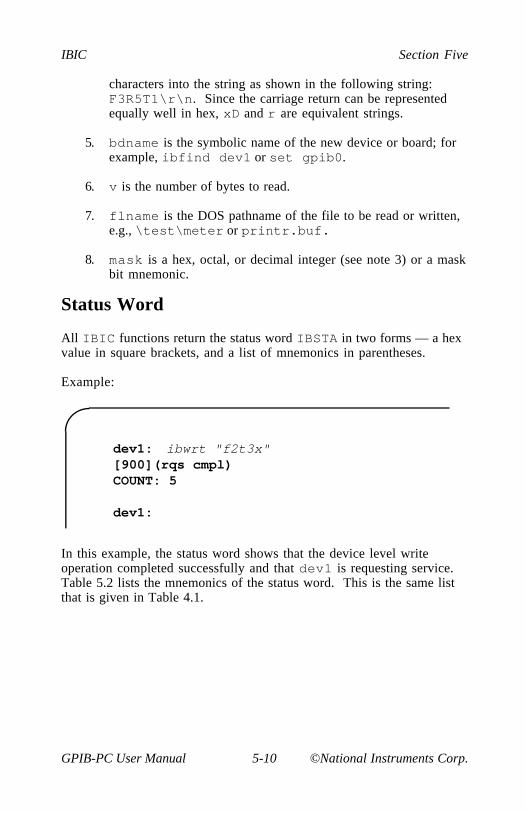
IBIC Section Five
GPIB-PC User Manual 5-10 ©National Instruments Corp.
characters into the string as shown in the following string:F3R5T1\r\n. Since the carriage return can be representedequally well in hex, xD and r are equivalent strings.
5. bdname is the symbolic name of the new device or board; forexample, ibfind dev1 or set gpib0.
6. v is the number of bytes to read.
7. flname is the DOS pathname of the file to be read or written,e.g., \test\meter or printr.buf.
8. mask is a hex, octal, or decimal integer (see note 3) or a maskbit mnemonic.
Status Word
All IBIC functions return the status word IBSTA in two forms — a hexvalue in square brackets, and a list of mnemonics in parentheses.
Example:
dev1:[900](rqs cmpl)COUNT: 5
dev1:
ibwrt "f2t3x"
In this example, the status word shows that the device level writeoperation completed successfully and that dev1 is requesting service.Table 5.2 lists the mnemonics of the status word. This is the same listthat is given in Table 4.1.

Section Five IBIC
©National Instruments Corp. 5-11 GPIB-PC User Manual
Table 5.2 - Status Word Layout
Mnemonics Bit Hex Function DescriptionPos. Value Type
ERR 15 8000 db GPIB errorTIMO 14 4000 db Time limit exceededEND 13 2000 db END or EOS detectedSRQI 12 1000 b SRQ interrupt receivedRQS 11 800 d Device requestingserviceCMPL 8 100 db I/O completedLOK 7 80 b Lockout StateREM 6 40 b Remote StateCIC 5 20 b Controller-In-ChargeATN 4 10 b Attention is assertedTACS 3 8 b TalkerLACS 2 4 b ListenerDTAS 1 2 b Device Trigger StateDCAS 0 1 b Device Clear State
Error Code
If a GPIB-PC function completes with an error, IBIC also displays theerror mnemonic. The following example illustrates an error conditionoccurred in the data transfer.
Example:
dev1:[8100] (err cmpl)ERROR: ENOLCOUNT: 1
dev1:
ibwrt "f2t3x"
In this example, there are no Listeners; perhaps dev1 is powered off.
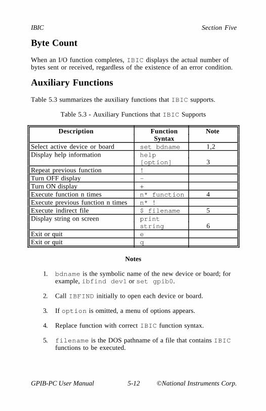
IBIC Section Five
GPIB-PC User Manual 5-12 ©National Instruments Corp.
Byte Count
When an I/O function completes, IBIC displays the actual number ofbytes sent or received, regardless of the existence of an error condition.
Auxiliary Functions
Table 5.3 summarizes the auxiliary functions that IBIC supports.
Table 5.3 - Auxiliary Functions that IBIC Supports
Description Function NoteSyntax
Select active device or board set bdname 1,2Display help information help
[option] 3Repeat previous function !Turn OFF display -Turn ON display +Execute function n times n* function 4Execute previous function n times n* !Execute indirect file $ filename 5Display string on screen print
string 6Exit or quit eExit or quit q
Notes
1. bdname is the symbolic name of the new device or board; forexample, ibfind dev1 or set gpib0.
2. Call IBFIND initially to open each device or board.
3. If option is omitted, a menu of options appears.
4. Replace function with correct IBIC function syntax.
5. filename is the DOS pathname of a file that contains IBICfunctions to be executed.

Section Five IBIC
©National Instruments Corp. 5-13 GPIB-PC User Manual
6. string consists of a list of ASCII characters, octal or hexbytes, or special symbols. The entire sequence of charactersmust be enclosed in quotes. An octal byte consists of abackslash character followed by the octal value. For example,octal 40 would be represented by 040. A hex byte consists of abackslash character and a character x followed by the hexvalue. For example, hex 40 would be represented by x40. Thetwo special symbols are \r for a carriage return character and\n for a linefeed character. These symbols provide a moreconvenient method for inserting the carriage return and linefeedcharacters into the string as shown in this string:"F3R5T1\r\n". Since the carriage return can be representedequally well in hex, \xD and \r are equivalent strings.
SET (Select Device or Board)
The SET function specifies a previously opened device or board to beused for subsequent GPIB-PC functions executed from IBIC. SETeliminates the need to include the BD unit descriptor in each GPIB-PCfunction call.
The argument bdname is any of the symbolic device or board namesrecognized by the handler. These are the default names gpib0,gpib1, and dev1 through dev16 unless the device names have beenchanged with IBCONF.
An example of the SET function appeared earlier in this section.
HELP (Display Help Information)
The HELP function gives causal information about IBIC and itsfunctions to be displayed on the screen.
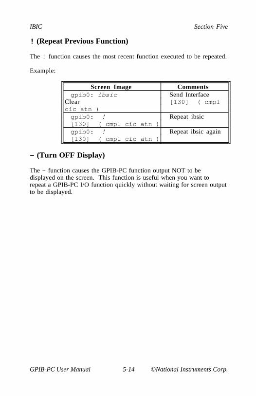
IBIC Section Five
GPIB-PC User Manual 5-14 ©National Instruments Corp.
! (Repeat Previous Function)
The ! function causes the most recent function executed to be repeated.
Example:
Screen Image Commentsgpib0: ibsic Send Interface
Clear [130] ( cmplcic atn )gpib0: ! Repeat ibsic[130] ( cmpl cic atn )gpib0: ! Repeat ibsic again[130] ( cmpl cic atn )
- (Turn OFF Display)
The - function causes the GPIB-PC function output NOT to bedisplayed on the screen. This function is useful when you want torepeat a GPIB-PC I/O function quickly without waiting for screen outputto be displayed.
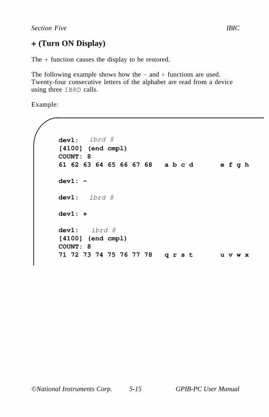
Section Five IBIC
©National Instruments Corp. 5-15 GPIB-PC User Manual
+ (Turn ON Display)
The + function causes the display to be restored.
The following example shows how the - and + functions are used.Twenty-four consecutive letters of the alphabet are read from a deviceusing three IBRD calls.
Example:
dev1:[4100] (end cmpl)COUNT: 861 62 63 64 65 66 67 68 a b c d e f g h
dev1: -
dev1:
dev1: +
dev1:[4100] (end cmpl)COUNT: 871 72 73 74 75 76 77 78 q r s t u v w x
ibrd 8
ibrd 8
ibrd 8
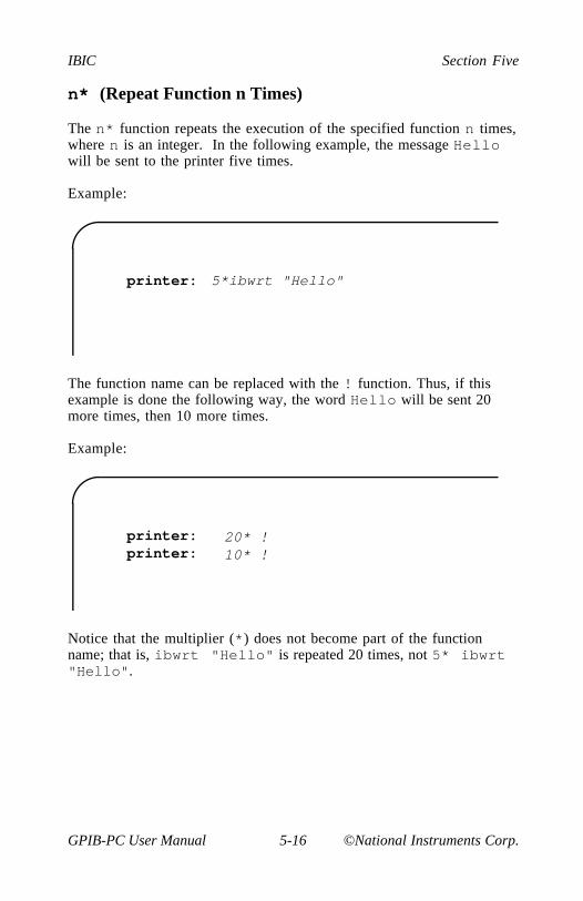
IBIC Section Five
GPIB-PC User Manual 5-16 ©National Instruments Corp.
n* (Repeat Function n Times)
The n* function repeats the execution of the specified function n times,where n is an integer. In the following example, the message Hellowill be sent to the printer five times.
Example:
printer: 5*ibwrt "Hello"
The function name can be replaced with the ! function. Thus, if thisexample is done the following way, the word Hello will be sent 20more times, then 10 more times.
Example:
printer:printer:
20* !10* !
Notice that the multiplier (*) does not become part of the functionname; that is, ibwrt "Hello" is repeated 20 times, not 5* ibwrt"Hello".

Section Five IBIC
©National Instruments Corp. 5-17 GPIB-PC User Manual
$ (Execute Indirect File)
In the $ function, an indirect file is a text file that contains IBICfunctions. It is similar to a DOS batch file and is created the same way.This function reads the specified indirect file and executes the IBICfunctions in sequence as if they were entered in that order from thekeyboard.
Example:
gpib0: $ usrfile
executes the IBIC functions listed in the file usrfile, and
gpib0: 3*$ usrfile
repeats that operation three times.
The display mode, in effect before this function is executed, is restoredafterward but may be changed by functions in the indirect file.

IBIC Section Five
GPIB-PC User Manual 5-18 ©National Instruments Corp.
PRINT (Display the ASCII String)
The PRINT function can be used to echo a string to the screen.
Example:
dev1:hellodev1: andgoodbye
print "hello"
print "and\r\n\x67\x6f\x6f\x64\x62\x79\x65"
PRINT can be used to display comments from indirect files. The printstrings will appear even if the display is suppressed with the - function.
The second PRINT example illustrates the use of hex values in IBICstrings.
E or Q (exit or quit)
The DOS exit command or the IBIC function E or Q returns you toDOS.

Section Five IBIC
©National Instruments Corp. 5-19 GPIB-PC User Manual
IBIC Sample Programs
Refer to Section Four A, BASICA/QuickBASIC GPIB ProgrammingExamples, for a description of the programming steps that could be usedto program a representative IEEE-488 instrument from your personalcomputer using the GPIB-PC handler functions. The applications arewritten using IBIC commands.
Device Function Calls
To communicate with a device, first "find" the device name which wasgiven to the device in the IBCONF program.
Example:
DVM:
:ibfind dvm
Clear the device. The user should check for ERR after each GPIBfunction call to be safe.
Example:
DVM:[0100] (cmpl)
ibclr

IBIC Section Five
GPIB-PC User Manual 5-20 ©National Instruments Corp.
Write the function, range, and trigger source instructions to the DVM.
Example:
DVM:[0100] (cmpl)count: 6
ibwrt "F3R7T3"
Trigger the device.
Example:
DVM:[0100] (cmpl)
ibtrg
Wait for the DVM to request service or for a timeout; if the currenttimeout limit is too short, use ibtmo to change it.
Example:
DVM:[800] (rqs)
ibwait (TIMO RQS)
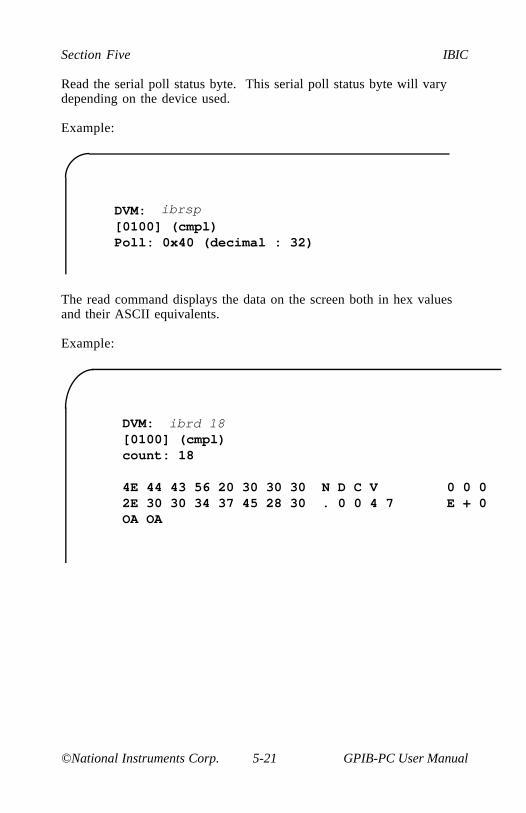
Section Five IBIC
©National Instruments Corp. 5-21 GPIB-PC User Manual
Read the serial poll status byte. This serial poll status byte will varydepending on the device used.
Example:
DVM:[0100] (cmpl)Poll: 0x40 (decimal : 32)
ibrsp
The read command displays the data on the screen both in hex valuesand their ASCII equivalents.
Example:
DVM:[0100] (cmpl)count: 18
4E 44 43 56 20 30 30 30 N D C V 0 0 02E 30 30 34 37 45 28 30 . 0 0 4 7 E + 0OA OA
ibrd 18
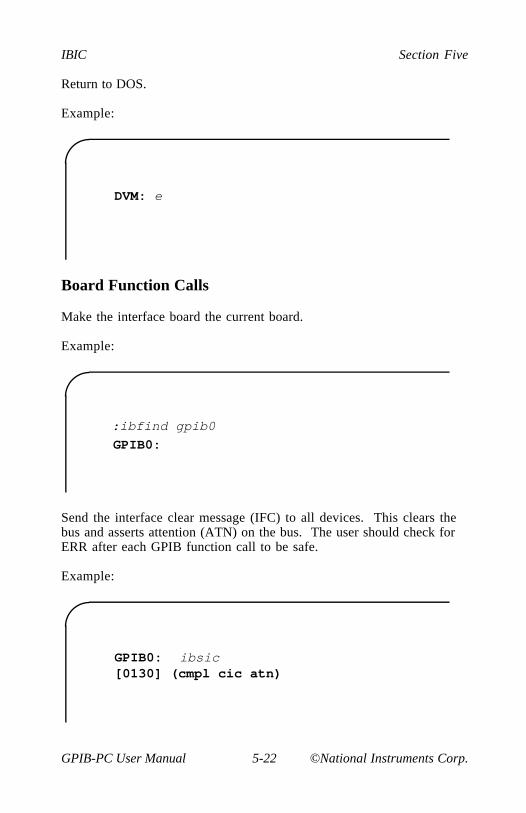
IBIC Section Five
GPIB-PC User Manual 5-22 ©National Instruments Corp.
Return to DOS.
Example:
DVM: e
Board Function Calls
Make the interface board the current board.
Example:
:ibfind gpib0
GPIB0:
Send the interface clear message (IFC) to all devices. This clears thebus and asserts attention (ATN) on the bus. The user should check forERR after each GPIB function call to be safe.
Example:
GPIB0:[0130] (cmpl cic atn)
ibsic
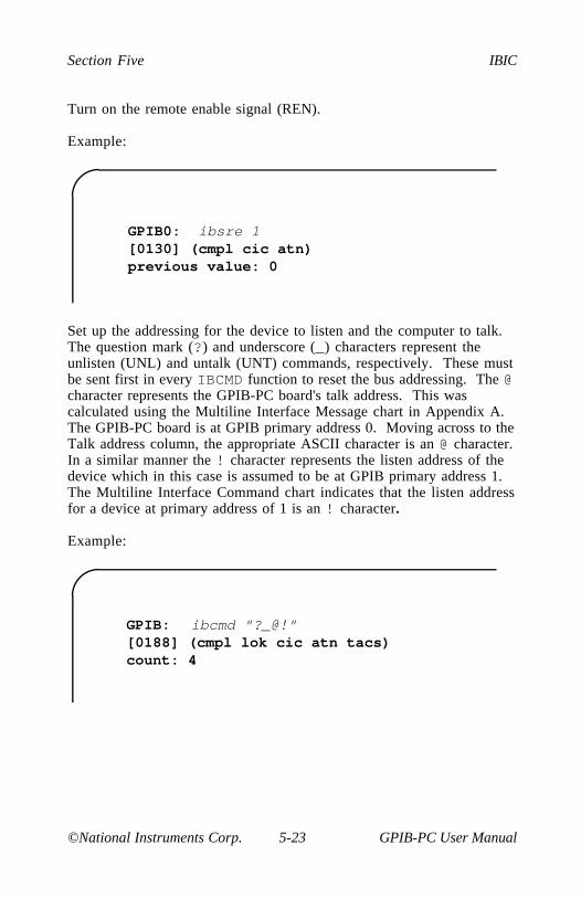
Section Five IBIC
©National Instruments Corp. 5-23 GPIB-PC User Manual
Turn on the remote enable signal (REN).
Example:
GPIB0:[0130] (cmpl cic atn)previous value: 0
ibsre 1
Set up the addressing for the device to listen and the computer to talk.The question mark (?) and underscore (_) characters represent theunlisten (UNL) and untalk (UNT) commands, respectively. These mustbe sent first in every IBCMD function to reset the bus addressing. The @character represents the GPIB-PC board's talk address. This wascalculated using the Multiline Interface Message chart in Appendix A.The GPIB-PC board is at GPIB primary address 0. Moving across to theTalk address column, the appropriate ASCII character is an @ character.In a similar manner the ! character represents the listen address of thedevice which in this case is assumed to be at GPIB primary address 1.The Multiline Interface Command chart indicates that the listen addressfor a device at primary address of 1 is an ! character.
Example:
GPIB:[0188] (cmpl lok cic atn tacs)count: 4
ibcmd "?_@!"
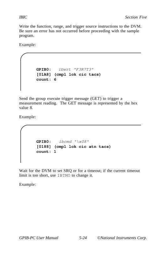
IBIC Section Five
GPIB-PC User Manual 5-24 ©National Instruments Corp.
Write the function, range, and trigger source instructions to the DVM.Be sure an error has not occurred before proceeding with the sampleprogram.
Example:
GPIB0: [01A8] (cmpl lok cic tacs)count: 6
ibwrt "F3R7T3"
Send the group execute trigger message (GET) to trigger ameasurement reading. The GET message is represented by the hexvalue 8.
Example:
GPIB0:[0188] (cmpl lok cic atn tacs)count: 1
ibcmd "\x08"
Wait for the DVM to set SRQ or for a timeout; if the current timeoutlimit is too short, use IBTMO to change it.
Example:
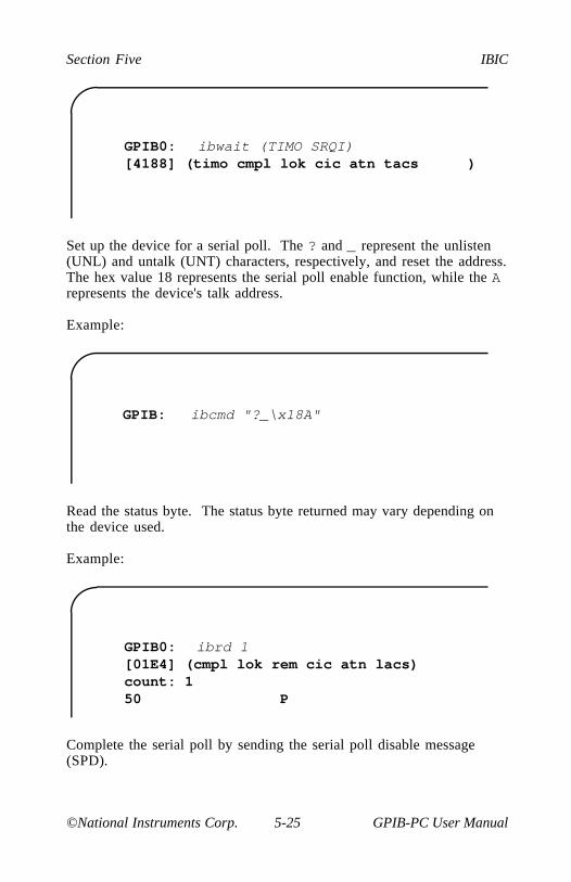
Section Five IBIC
©National Instruments Corp. 5-25 GPIB-PC User Manual
GPIB0:[4188] (timo cmpl lok cic atn tacs )
ibwait (TIMO SRQI)
Set up the device for a serial poll. The ? and _ represent the unlisten(UNL) and untalk (UNT) characters, respectively, and reset the address.The hex value 18 represents the serial poll enable function, while the Arepresents the device's talk address.
Example:
GPIB: ibcmd "?_\x18A"
Read the status byte. The status byte returned may vary depending onthe device used.
Example:
GPIB0:[01E4] (cmpl lok rem cic atn lacs)count: 150P
ibrd 1
Complete the serial poll by sending the serial poll disable message(SPD).

IBIC Section Five
GPIB-PC User Manual 5-26 ©National Instruments Corp.
Example:
GPIB0: [01F4] (cmpl lok rem cic atn lacs)count: 1
ibcmd "\x19"
Since the DVM and the GPIB-PC are still addressed to talk and tolisten, the measurement can be read.
Example:
GPIB0:[01E4] (cmpl lok rem cic lacs)0D 0A 4E 44 43 56 2D 30• • N D C V - 030 30 2E 30 30 34 37 450 0 . 0 0 4 7 E2B 30 0D 0A + 0 • •
ibrd 20
To close out a programming sequence, send the interface clear message(IFC) to initialize the bus.
Example:
GPIB:[0160} (cmpl lok rem cic)
ibsic
Return to DOS.

Section Five IBIC
©National Instruments Corp. 5-27 GPIB-PC User Manual
Example:
GPIB0: e

©National Instruments Corp. 6-1 GPIB-PC User Manual
Section Six - Applications Monitor
The applications monitor is a memory resident program which is usefulin debugging sequences of GPIB calls from within your application.The monitor provides the capability to trap on return from GPIB drivercalls, allowing you to inspect function arguments, buffers, return values,GPIB global variables, and other pertinent data. You may select thetrap so that it occurs on return from every GPIB handler call, returnsonly on those calls which return an error indication; or occurs only onthose calls which are returned with particular bit patterns in the GPIBstatus word.
While trapped, you will see a popup screen (Figure 6.1) that providesdetails of the call being trapped. In addition, you can view a listing ofup to 255 of the preceding calls to verify that the sequence of calls andtheir arguments have occurred as intended.
Figure 6.1 - Applications Monitor Popup Screen

IBIC Section Six
GPIB-PC User Manual 6-2 ©National Instruments Corp.
In many cases, use of the applications monitor allows you to omitexplicit error-checking code from the application. If a program isexpected to run without errors, trapping on errors will cause the monitorto be invoked only if an error occurs during a GPIB call. You may thentake the action necessary to fix the problem.
Currently, the applications monitor is only supported by the RevisionC.5.1 and later versions of the GPIB Rev. C handler.
Installing the Applications Monitor
The applications monitor is included on the distribution diskette as thefile APPMON.COM. To install it, type the following command inresponse to the DOS prompt:
APPMON
If the GPIB handler is not present or the monitor has been previouslyinstalled, it will not load and an error message will be printed.
Once run, the monitor will remain resident in memory until you rebootthe system. Should you later desire that you no longer wish to devotememory to the resident applications monitor, simply reboot your system;the monitor will no longer be loaded.
IBTRAP
The applications monitor provides the capability to trap on GPIBhandler calls which have particular bits set in the GPIB status word.The trap options are set by the special GPIB handler call, IBTRAP.This call can be made either from the application program, or from thespecial utility program called IBTRAP.EXE.
Both the function call and the DOS utility allow you to select a mask,which determines those functions which will be trapped, and a monitormode, which selects what is to be displayed when a call is trapped.
The exact syntax of the function call is dependent on the language youare using. See the description of IBTRAP in your language section fordetails on including IBTRAP calls in your application.
The utility program IBTRAP may be used to set the trap mode fromDOS. Simply type IBTRAP in response to the DOS prompt, specifying
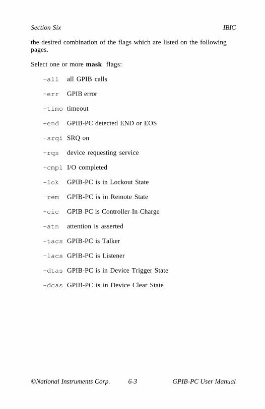
Section Six IBIC
©National Instruments Corp. 6-3 GPIB-PC User Manual
the desired combination of the flags which are listed on the followingpages.
Select one or more mask flags:
-all all GPIB calls
-err GPIB error
-timo timeout
-end GPIB-PC detected END or EOS
-srqi SRQ on
-rqs device requesting service
-cmpl I/O completed
-lok GPIB-PC is in Lockout State
-rem GPIB-PC is in Remote State
-cic GPIB-PC is Controller-In-Charge
-atn attention is asserted
-tacs GPIB-PC is Talker
-lacs GPIB-PC is Listener
-dtas GPIB-PC is in Device Trigger State
-dcas GPIB-PC is in Device Clear State
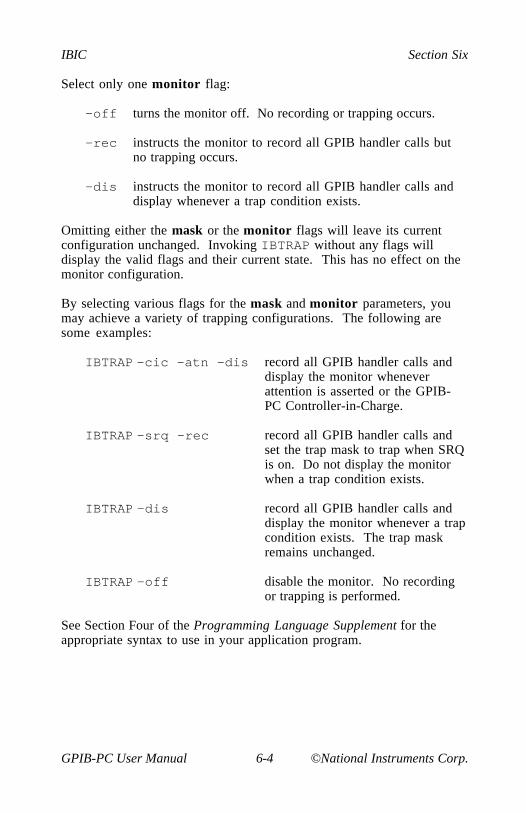
IBIC Section Six
GPIB-PC User Manual 6-4 ©National Instruments Corp.
Select only one monitor flag:
-off turns the monitor off. No recording or trapping occurs.
-rec instructs the monitor to record all GPIB handler calls butno trapping occurs.
-dis instructs the monitor to record all GPIB handler calls anddisplay whenever a trap condition exists.
Omitting either the mask or the monitor flags will leave its currentconfiguration unchanged. Invoking IBTRAP without any flags willdisplay the valid flags and their current state. This has no effect on themonitor configuration.
By selecting various flags for the mask and monitor parameters, youmay achieve a variety of trapping configurations. The following aresome examples:
IBTRAP -cic -atn -dis record all GPIB handler calls anddisplay the monitor wheneverattention is asserted or the GPIB-PC Controller-in-Charge.
IBTRAP -srq -rec record all GPIB handler calls andset the trap mask to trap when SRQis on. Do not display the monitorwhen a trap condition exists.
IBTRAP -dis record all GPIB handler calls anddisplay the monitor whenever a trapcondition exists. The trap maskremains unchanged.
IBTRAP -off disable the monitor. No recordingor trapping is performed.
See Section Four of the Programming Language Supplement for theappropriate syntax to use in your application program.

Section Six IBIC
©National Instruments Corp. 6-5 GPIB-PC User Manual
Applications Monitor Options
When displayed, the applications monitor allows you to view theparameters of the current GPIB call, change the display and trap modes,and scan the GPIB session summary. The monitor displays thefollowing information pertinent to the current GPIB call:
Device symbolic device name.
Function GPIB-PC function mnemonic and description.
Value for functions that have a number as their secondparameter, this contains its value, otherwise it isundefined.
Count for functions that have a count as their thirdparameter this contains its value, otherwise it isundefined.
IBSTA contains the GPIB status information.
IBERR contains the GPIB error information, or theprevious value of the value parameter if no erroroccurred.
IBCNT contains the number of bytes transferred.
Buffer for functions that have a buffer as a parameter, thisValue displays its contents. Each byte of the buffer is
shown with its index, character image, and ASCIIvalue.
Status shows the state of the individual bits of IBSTA. A"*" indicated the bit is active. The active bits ofthe trap mask are highlighted for easyidentification.
Error shows the state of the individual bits of IBERR. A"*" indicates the bit is active.
Information contains any message concerning the current GPIBcall.
IBIC Section Six
GPIB-PC User Manual 6-6 ©National Instruments Corp.
NOTE: All numbers are displayed in hexadecimal. Also, the monitor isunable to record IBFIND or IBTRAP calls.

Section Six IBIC
©National Instruments Corp. 6-7 GPIB-PC User Manual
Main Commands
When the main monitor screen is displayed, the following commandkeys are available:
F1 continue executing applications program
F2 display session summary
F5 configure trap mask
F6 configure monitor mode
F7 hide/show monitor
F8 clear session summary buffer
F10 display command key list
Cursor Up scroll buffer up one character
Cursor Down scroll buffer down one character
Page Up scroll buffer up one page
Page Down scroll buffer down one page
Home scroll to beginning of buffer
End scroll to end of buffer

IBIC Section Six
GPIB-PC User Manual 6-8 ©National Instruments Corp.
Session Summary Screen
This session summary can be viewed by pressing F2. Once displayed,the following keys can be used to manipulate the display:
Cursor Up scrolls summary up one line
Cursor Down scrolls summary down one line
Page Up scrolls summary up one page
Page Down scrolls summary down one page
Home scrolls to the top of summary
End scrolls to the end of summary
Escape or F2 exit the session summary display and return to themain monitor screen
Configuring the Trap Mask
Pressing F5 allows you to change the current configuration of the trapmask. It yields a popup menu with each of the status bits displayedalong with their current state (either ON or OFF). Use the UP andDOWN arrow keys to highlight the desired bit and press F1 to toggle itsstate. Pressing ENTER will record the changes. Pressing ESCAPE willcancel this action and leave the mask unchanged. Selecting all bits hasthe effect of trapping on every call, while turning them all off causes notrapping to occur.
Configuring the Monitor Mode
Pressing F6 allows you to change the current configuration of themonitor mode. It yields a popup menu with the current modecheckmarked. Use the up and down arrow keys to highlight the newmode and press ENTER to record the change. Pressing ESCAPE willcancel this action and leave the mode unchanged.

Section Six IBIC
©National Instruments Corp. 6-9 GPIB-PC User Manual
Hiding and Showing the Monitor
Pressing F7 will hide the monitor and restore the contents of the screen.This allows you to view program output written to the screen whileactive within the monitor. Pressing F7 again will restore the monitor.
©National Instruments Corp. A-1 GPIB-PC User Manual
Appendix A - Multiline InterfaceMessages
The following tables are multiline interface messages (sent andreceived with ATN TRUE).
The subsequent pages contain an interface message reference list,which describes the mnemonics and messages which correspond to theinterface functions.

Multiline Interface Messages Appendix A
GPIB-PC User Manual A-2 ©National Instruments Corp.
Multiline Interface Messages
H e x Oct D e c ASCII Msg H e x Oct D e c ASCII M s g
00 000 0 NUL 20 040 32 SP MLA001 001 1 SOH GTL 21 041 33 ! MLA102 002 2 STX 22 042 34 " MLA203 003 3 ETX 23 043 35 # MLA304 004 4 EOT SDC 24 044 36 $ MLA405 005 5 ENQ PPC 25 045 37 % MLA506 006 6 ACK 26 046 38 & MLA607 007 7 BEL 27 047 39 ' MLA7
08 010 8 BS GET 28 050 40 ( MLA809 011 9 HT TCT 29 051 41 ) MLA90A 012 10 LF 2A 052 42 * MLA100B 013 11 VT 2B 053 43 + MLA110C 014 12 FF 2C 054 44 , MLA120D 015 13 CR 2D 055 45 - MLA130E 016 14 SO 2E 056 46 . MLA140F 017 15 SI 2F 057 47 / MLA15
10 020 16 DLE 30 060 48 0 MLA1611 021 17 DC1 LLO 31 061 49 1 MLA1712 022 18 DC2 32 062 50 2 MLA1813 023 19 DC3 33 063 51 3 MLA1914 024 20 DC4 DCL 34 064 52 4 MLA2015 025 21 NAK PPU 35 065 53 5 MLA2116 026 22 SYN 36 066 54 6 MLA2217 027 23 ETB 37 067 55 7 MLA23
18 030 24 CAN SPE 38 070 56 8 MLA2419 031 25 E M SPD 39 071 57 9 MLA251A 032 26 SUB 3A 072 58 : MLA261B 033 27 ESC 3B 073 59 ; MLA271C 034 28 FS 3C 074 60 < MLA281D 035 29 GS 3D 075 61 = MLA291E 036 30 RS 3E 076 62 > MLA301F 037 31 US 3F 077 63 ? UNL
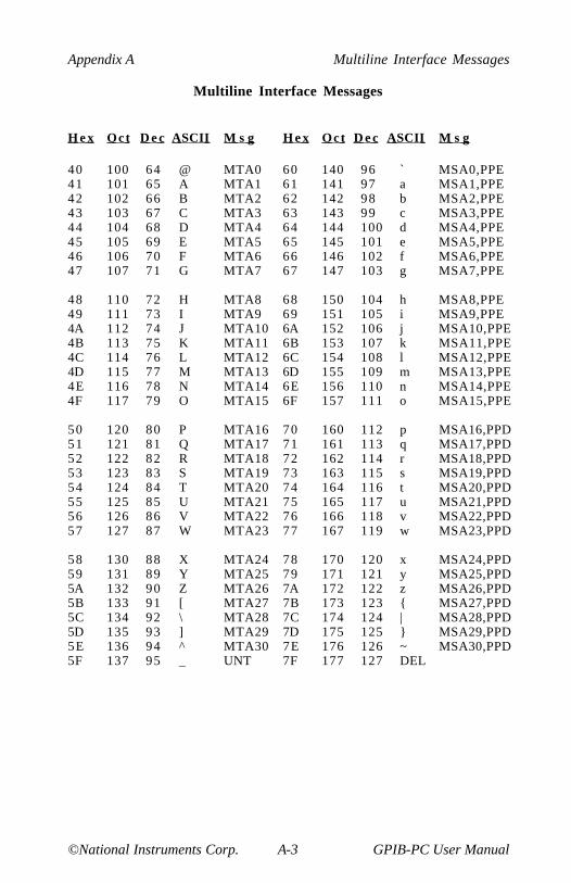
Appendix A Multiline Interface Messages
©National Instruments Corp. A-3 GPIB-PC User Manual
Multiline Interface Messages
H e x Oct D e c ASCII M s g H e x Oct D e c ASCII M s g
40 100 64 @ MTA0 60 140 96 ` MSA0,PPE41 101 65 A MTA1 61 141 97 a MSA1,PPE42 102 66 B MTA2 62 142 98 b MSA2,PPE43 103 67 C MTA3 63 143 99 c MSA3,PPE44 104 68 D MTA4 64 144 100 d MSA4,PPE45 105 69 E MTA5 65 145 101 e MSA5,PPE46 106 70 F MTA6 66 146 102 f MSA6,PPE47 107 71 G MTA7 67 147 103 g MSA7,PPE
48 110 72 H MTA8 68 150 104 h MSA8,PPE49 111 73 I MTA9 69 151 105 i MSA9,PPE4A 112 74 J MTA10 6A 152 106 j MSA10,PPE4B 113 75 K MTA11 6B 153 107 k MSA11,PPE4C 114 76 L MTA12 6C 154 108 l MSA12,PPE4D 115 77 M MTA13 6D 155 109 m MSA13,PPE4E 116 78 N MTA14 6E 156 110 n MSA14,PPE4F 117 79 O MTA15 6F 157 111 o MSA15,PPE
50 120 80 P MTA16 70 160 112 p MSA16,PPD51 121 81 Q MTA17 71 161 113 q MSA17,PPD52 122 82 R MTA18 72 162 114 r MSA18,PPD53 123 83 S MTA19 73 163 115 s MSA19,PPD54 124 84 T MTA20 74 164 116 t MSA20,PPD55 125 85 U MTA21 75 165 117 u MSA21,PPD56 126 86 V MTA22 76 166 118 v MSA22,PPD57 127 87 W MTA23 77 167 119 w MSA23,PPD
58 130 88 X MTA24 78 170 120 x MSA24,PPD59 131 89 Y MTA25 79 171 121 y MSA25,PPD5A 132 90 Z MTA26 7A 172 122 z MSA26,PPD5B 133 91 [ MTA27 7B 173 123 { MSA27,PPD5C 134 92 \ MTA28 7C 174 124 | MSA28,PPD5D 135 93 ] MTA29 7D 175 125 } MSA29,PPD5E 136 94 ^ MTA30 7E 176 126 ~ MSA30,PPD5F 137 95 _ UNT 7F 177 127 DEL

Multiline Interface Messages Appendix A
GPIB-PC User Manual A-4 ©National Instruments Corp.
Interface Message Reference List
Mnemonic M e s s a g e Interface Function(s)
LOCAL MESSAGES RECEIVED (by interface functions)
gts go to standby Cist individual status qualifier P Plon listen only L, LE[lpe] local poll enable P Pltn listen L, LElun local unlisten L, LEnba new byte available SHpon power on SH, AH, T, TE, L, LE, SR, RL, PP, Crdy ready AHrpp request parallel poll Crsc request system control Crsv request service SRrtl return to local R Lsic send interface clear Csre send remote enable Ctca take control asynchronously Ctcs take control synchronously AH, Cton talk only T, TE
REMOTE MESSAGES RECEIVED
ATN attention SH, AH, T, TE, L, LE, PP, CDAB data byte (via L, LE)DAC data accepted SHDAV data valid AHDCL device clear DCEND end (via L, LE)GET group execute trigger DTGTL go to local R LIDY identify L, LE, PPIFC interface clear T, TE, L, LE, CLLO local lockout R LMLA my listen address L, LE, RL[MLA] my listen address TMSA or [MSA] my secondary address TE, LEMTA my talk address T, TE[MTA] my talk address LOSA other secondary address TEOTA other talk address T, TEPCG primary command group TE, LE, PPPPC parallel poll configure P P[PPD] parallel poll disable P P[PPE] parallel poll enable P PPPRn parallel poll response n (via C)PPU parallel poll unconfigure P P

Appendix A Multiline Interface Messages
©National Instruments Corp. A-5 GPIB-PC User Manual
Interface Message Reference List (Continued)
Mnemonic M e s s a g e Interface Function(s)
REMOTE MESSAGES RECEIVED (continued)
REN remote enable R LRFD ready for data SHRQS request service (via L, LE)[SDC] selected device clear DCSPD serial poll disable T, TESPE serial poll enable T, TESRQ service request (via C)STB status byte (via L, LE)TCT or [TCT] take control CUNL unlisten L, LE
REMOTE MESSAGES SENT
ATN attention CDAB data byteDAC data accepted AHDAV data valid SHDCL device clear (via C)END end (via T)GET group execute trigger (via C)GTL go to local (via C)IDY identify CIFC interface clear CLLO local lockout (via C)MLA or [MLA] my listen address (via C)MSA or [MSA] my secondary address (via C)MTA or [MTA] my talk address (via C)OSA other secondary address (via C)OTA other talk address (via C)PCG primary command group (via C)PPC parallel poll configure (via C)[PPD] parallel poll disable (via C)[PPE] parallel poll enable (via C)PPRn parallel poll response n P PPPU parallel poll unconfigure (via C)REN remote enable CRFD ready for data AHRQS request service T, TE[SDC] selected device clear (via C)SPD serial poll disable (via C)SPE serial poll enable (via C)SRQ service request SRSTB status byte (via T, TE)TCT take control (via C)UNL unlisten (via C)UNT untalk (via C)
©National Instruments Corp. B-1 GPIB-PC User Manual
Appendix B - Common Errors andTheir Solutions Some errors occur more frequently than others. These common errorsand their solutions are listed in this appendix, according to the errorcode that was returned from the function as indicated by IBERR. A fullexplanation of all possible errors is in Section Four. Later in thisappendix are descriptions of error situations that do not return an errorcode.
EDVR(0)
Error Condition: DOS error (see IBCNT for DOS error code).
Solutions:
• Check that GPIB.COM, CONFIG.SYS, and IBCONF.EXE arein the root directory of your boot drive. (Enter DIR \ from theboot drive and verify that these files exist).
• Check that CONFIG.SYS contains the lineDEVICE=GPIB.COM. (Enter TYPE \CONFIG.SYS from theboot drive and verify that the line exists there).
• Reboot your system after you install the software.
ECIC(1)
Error Condition: Function requires GPIB-PC to be Controller-In-Charge.
Solutions:
• Run IBCONF and make sure the board being used (GPIB0 orGPIB1) is configured to be the System Controller.
• If executing board functions, call IBSIC to become Controller-In-Charge before any other function calls that require thatcapability.
• If control has been passed away with an IBPCT call, wait for itto be returned with the IBWAIT function.

Common Errors and Their Solutions Appendix B
GPIB-PC User Manual B-2 ©National Instruments Corp.
ENOL(2)
Error Condition: Write function detected no Listeners.
Solutions:
• Check that the device is powered on, and also that at least two-thirds of the devices on the GPIB are turned on.
• Inspect the interconnecting cable to see that the devices areattached and that the connectors are seated properly.
• Check the switches or control panel of the device and makesure its GPIB address is what you think it is. Check alsowhether the device uses extended addressing and requires aprimary and secondary address. (Some devices use multiplesecondary addresses to enable different internal functions).
• For device write functions, run IBCONF from the root directoryand check that the device's address (including secondaryaddress) is correct. If a change is made, reboot the system.Then run IBIC to verify that the address is correct, as follows.Open the device you want to write to using IBFIND andexecute IBPAD and IBSAD calls, passing each the addressvalue you believe is correct. If secondary addressing is notused, pass a value of zero to the IBSAD function. Assumingthese calls do NOT return with an error, IBIC will return theprevious address value, which will be the same as the new oneif you have correctly configured the device.
• For board write functions, make sure the device is addressedproperly using the IBCMD function before the write call. Verifythat the low five bits of the listen address (and if appropriatethe secondary address) used in the IBCMD call match thedevice's GPIB address(es) and also that the listen address is inthe range 20-3E hex (32-62 decimal) and the secondary addressis in the range 60-7E hex (92-126 decimal).

Appendix B Common Errors and Their Solutions
©National Instruments Corp. B-3 GPIB-PC User Manual
EADR(3)
Error Condition: GPIB-PC (GPIB0 or GPIB1) is not addressedcorrectly.
Solutions:
• Use IBCMD to send the appropriate Talk or Listen addressbefore attempting an IBWRT or IBRD.
• If calling IBGTS with the shadow handshake feature, callIBCMD to ensure that the GPIB ATN line is asserted.
EARG(4)
Error Condition: Invalid argument to function call.
Solutions:
• Errors received from IBIC:
- Verify syntax in Section Five.
- Make sure the address of the board in IBCONF does notconflict with that of a device.
• Errors received when running your application program:
- Verify syntax in Section Four.
- Make sure the address of the board in IBCONF does notconflict with that of a device.
Common Errors and Their Solutions Appendix B
GPIB-PC User Manual B-4 ©National Instruments Corp.
ESAC(5)
Error Condition: GPIB-PC not System Controller as required.
Solutions:
• Run IBCONF and make sure the board (GPIB0 or GPIB1) isconfigured to be System Controller.
• Issue a board IBRSC function call with a value of 1 to requestSystem Control.
EABO(6)
Error Condition: I/O operation aborted.
Solutions:
• Check that the device is powered on.
• Verify proper cable connections.
• Errors received from IBRD:
- Some devices will not send data unless they have receiveddata telling them what to send. This is caused by deviceshaving the capability of sending several types of data.Issue an IBWRT to set up the device, and then an IBRD toreceive the information.
- If you have not changed any of the default EOS or EOIsettings in IBCONF, the reads will terminate when thebuffer is full or when EOI is set. If your device sends anEOS terminating character such as a carriage return ratherthan EOI, then use IBCONF to change the devicecharacteristics. Remember to reboot after leaving IBCONFif you made any changes.
Appendix B Common Errors and Their Solutions
©National Instruments Corp. B-5 GPIB-PC User Manual
ENEB(7)
Error Condition: Non-existent GPIB-PC board.
Solution:
• Run IBCONF and make sure the board type (GPIB-PCII, PCIIAor PCIII) and base I/O address match the hardware and addressswitch settings. If you make any changes, reboot after leavingIBCONF.
EOIP(10)
Error Conditions: I/O started before previous operation completed.
Solution:
• When using asynchronous reads or writes, call IBWAIT to waitfor CMPL status before making another call.
ECAP(11)
Error Condition: No capability for operation.
Solution:
• Run IBCONF and verify that the capability to do a particularcall is enabled (e.g., you must be System Controller to executethe IBSRE function). Check both device and boardcapabilities. Reboot after leaving IBCONF if you made anychanges.
EFSO(12)
Error Condition: File system error.
Solutions:
• Check the disk files to make sure names are properly specifiedand that the file exists.
• If more room is needed on the disk, delete some files.
• Rename any files which have the same name given to a devicein IBCONF, or rename the device.

Common Errors and Their Solutions Appendix B
GPIB-PC User Manual B-6 ©National Instruments Corp.
EBUS(14)
Error Condition: Command error during device call.
Solutions:
• Find out which device is abnormally slow to accept commandsand fix the problem with the device.
• If more time is needed to send commands, lengthen the timelimit of the board in IBCONF or with IBTMO.
ESTB(15)
Error Condition: Serial poll status byte(s) lost.
Solutions:
• Call IBRSP more often to read the status bytes.
• Ignore ESTB.
ESRQ(16)
Error Condition: SRQ stuck in the ON position.
Solutions:
• Ignore ESRQ until all devices are found. It occurred becausethe device asserting SRQ was not opened with IBFIND. Theautomatic serial polling polls only the opened devices.
• Check that you have used IBFIND to open all devices on theGPIB that could assert SRQ. Remove any device from the busif it is not being accessed.
• Using IBIC, attach one device at a time and determine that itis unasserting SRQ after being polled.
• Inspect the interconnecting cable to see that the devices areattached and that the connectors are seated properly.

Appendix B Common Errors and Their Solutions
©National Instruments Corp. B-7 GPIB-PC User Manual
Other Error Conditions
Listed below are general errors which may occur when using the GPIB-PC hardware and software.
Error Condition: Attempts to run the GPIB utility programs, IBDIAG,IBTEST, or IBIC and returns Bad command or File Name errorfrom DOS. Also, the distribution files do not appear to be on the bootdisk after running IBSTART.
Solution:
• IBSTART copies the files to the subdirectory \GPIB-PC on theboot disk. Only GPIB.COM and IBCONF.EXE are copied tothe root directory. Change to the \GPIB-PC directory with theDOS command cd \GPIB-PC to run other programs.
Error Condition: Function call does not return and the program seemsto hang forever.
Solutions:
• Run IBCONF and confirm that the board's DMA channel andinterrupt line match the hardware settings. Then run IBTESTafter rebooting. Also check that the DMA channel and interruptline do not conflict with other devices in the computer.
• Check that the time limit is not set to zero, which results ininfinite time limits. To do this, run IBCONF and look at thetime limit value both for your device and your board. Or, fromIBIC, call IBTMO and pass to it the timeout argument valueyou believe is correct (the default is 13, which represents 10seconds). Assuming that the IBTMO call does not result in anerror, the previous value returned by the call will equal thevalue passed to it if the time limit was what you expected.
• Check that you do not call IBWAIT for an event that may nothappen without also waiting for TIMO as well. For example, ifyou fail to set the TIMO bit while waiting for RQS from adevice, and for some reason the device will not assert SRQ, theIBWAIT call will not return.
Common Errors and Their Solutions Appendix B
GPIB-PC User Manual B-8 ©National Instruments Corp.
• All device functions require the board to be Controller-In-Charge. If it is not, either because it is not System Controlleror because it has passed control away, the function will notreturn until control is passed back to the board. If this neverhappens, the function will never return. To check the board'sSystem Controller status, either run IBCONF and verify that theboard is configured to be System Controller, or run IBIC andexecute the function IBRSC with an argument of 1. Theprevious value is reported as 1 if the board was SystemController before your function call. To check that the boardhas not passed control, confirm that you never call IBPCT, norIBCMD with the Take Control command (9 hex) as anargument.
Error Condition: The computer crashes.
Solutions:
• Run IBCONF and confirm that the board's DMA channel andinterrupt line match the hardware settings. Also check that theDMA channel and interrupt line do not conflict with otherdevices in the computer.
• Configure the hardware and software to not use DMA and/orinterrupts. You may have a PC compatible that is not totallycompatible.
• Check that none of your device names is the same as any ofyour file or directory names, not including the file or directoryname suffix.
Error Condition: IBDIAG reports a DMA or interrupt problem.
Solutions:
• Reconfigure the hardware and software for another DMAchannel and/or interrupt line. You might have a conflict withanother device.
• With the GPIB-PCIIA and GPIB-PCIII, which have shareableinterrupt capability, check that another device on the same linereally has the shareable interrupt capability. Many do not.
• If an interrupt problem persists, configure the hardware andsoftware for non-DMA or non-interrupt operation. You mayhave a PC compatible that is not totally compatible.
Appendix B Common Errors and Their Solutions
©National Instruments Corp. B-9 GPIB-PC User Manual
Error Condition: IBIC reports an error on IBFIND or IBFIND returnsa negative unit descriptor.
Solutions:
• Check the solutions listed for EDVR, ENEB, or EARG errorcodes.
• Run IBCONF from the root directory to check that the device orboard name is correct.
Error Condition: The GPIB device being programmed appears toaccept the instruction but does not behave properly.
Solutions:
• Check that the instruction sent with the write function containsthe proper delimiters and message termination characters. Forexample, some devices require a carriage return and/or alinefeed character before they will execute the instruction.Other devices require special characters to separate multipleinstruction messages. Your instruction manual may beincomplete or ambiguous, so try several possible combinations.
• When running a program check for errors after each GPIB-PCfunction call . If an early call failed but you did not checkIBSTA, later functions will behave improperly and givemisleading status data.
• Check that the board you are using and the GPIB device youare programming are not at the same GPIB address. If usingdevice functions, run IBCONF to do this.

©National Instruments Corp. C-1 GPIB-PC User Manual
Appendix C - Differences BetweenSoftware Revisions
This appendix describes differences between current revisions of thesoftware.
Revision B and Revision C
Interrupts
In Rev. C, the software is interrupt driven, improving its performanceand taking advantage of the interrupt capabilities of the GPIB-PCinterface board.
Startup Program
The Rev. C standard software package includes a startup program(IBSTART.BAT) to get you started faster. Among other things, thisprogram creates or modifies your CONFIG.SYS file (IBCONF used todo this).
Configuration Program
In Rev. C, the configuration program, IBCONF.EXE, is streamlined andis easier to use. It no longer modifies CONFIG.SYS, since the start-upprogram now does this. The Automatic Serial Poll and Lockout featuresare now configurable at the board level.
Interface Bus Interactive Control Program (IBIC)
In Rev. C, IBIC.EXE includes a help feature. Also, you now callIBFIND as you would in your application program. It must be called atthe beginning of IBIC.EXE to enable a device or board, and be calledsubsequently to enable any previously unreferenced device or board.

Differences Between Software Revisions Appendix C
GPIB-PC User Manual C-2 ©National Instruments Corp.
New Functions
File I/O functions have been added to the handler, allowing data to beread into or written from a file. In Interpretive BASIC, integer I/Ofunctions have been added to allow the data to be stored in integerarrays instead of character strings.
Modified Functions
IBFIND no longer uses up available DOS file descriptors, so the TooMany Files error will not occur as a result of too many open boardsand devices. IBONL, when called with a 0, no longer invalidates theunit descriptor. It still disables the board or device, however.
Language Interfaces
If you customized a language interface for a compiler not supported inRev. B, it will need to be modified to work with Rev. C. This isbecause Rev. C language interfaces use a new, faster method ofentering the handler.
General
The Rev. C software package as a whole has been modified to allow itto run with a variety of GPIB-PC cards and systems.
Revision C and Revision D
Both Rev. C and Rev. D software are current and are actively supported.The one you receive depends on the GPIB-PC interface hardware youbuy.
Device Functions
Device I/O functions do not unaddress devices at the end of the call.Also, the functions do not address devices known to be alreadyaddressed from the previous call. This significantly improves through-put on multiple reads from or multiple writes to the same device.
Also in Rev. D, if the access board is not CIC when a device call ismade, the ECIC error is returned.
Non-Interrupt Mode
Rev. D has no non-interrupt mode. You must select interrupt level 2-7.

Appendix C Differences Between Software Revisions
©National Instruments Corp. C-3 GPIB-PC User Manual
Asynchronous I/O
There is no asynchronous capability on Rev. D. If you call anasynchronous function (IBRDA, IBRDIA, IBWRTA, IBWRTIA,IBCMDA, and IBSTOP) the ECAP error is returned immediately.
DMA on the GPIB-PCIII
The GPIB-PCIII board has additional DMA capability. If you have theGPIB-PCIII, consult the READ.ME file of the accompanying DistributionDiskette for details.
Local Lockout
In Rev. D there is no automatic local lockout configuration setting.Therefore, Rev. D does not place devices in lockout.
SRQI Status Bit
In Rev. D the SRQI status bit always reflects the current level of theSRQ line whether or not the GPIB-PC is CIC.
ATN and/or TIMO
With the IBWAIT function, it is not possible to wait for the ATN orTIMO conditions. If no other conditions exist, the function returnsimmediately.
DCAS and DTAS Status Bits
In Rev. D, these bits are cleared at the beginning of a new function call.Thus, if the application program must be sensitive to the messagesDevice Clear, Selected Device Clear, or Group Executive Trigger, thestatus bits must be checked after each function call.
Printer Support
Rev. C has printer support and Rev. D does not.
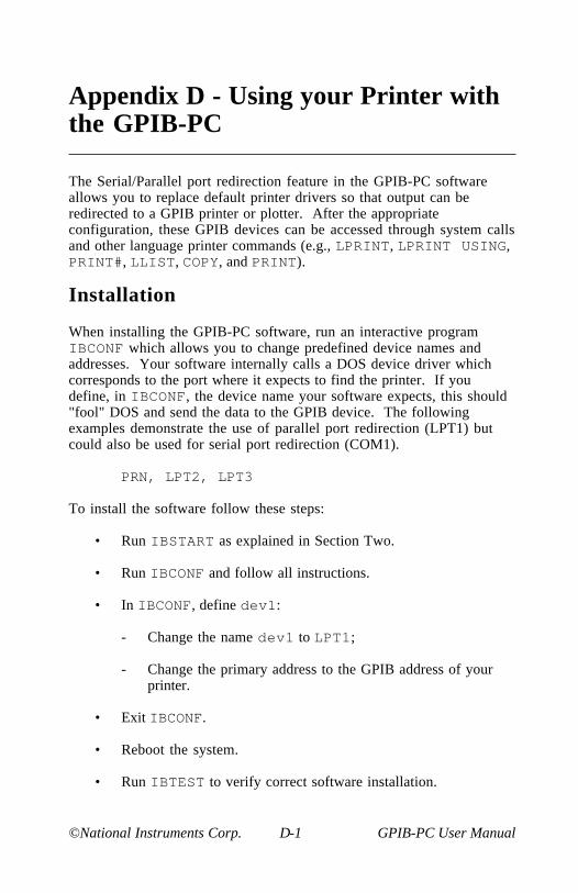
©National Instruments Corp. D-1 GPIB-PC User Manual
Appendix D - Using your Printer withthe GPIB-PC
The Serial/Parallel port redirection feature in the GPIB-PC softwareallows you to replace default printer drivers so that output can beredirected to a GPIB printer or plotter. After the appropriateconfiguration, these GPIB devices can be accessed through system callsand other language printer commands (e.g., LPRINT, LPRINT USING,PRINT#, LLIST, COPY, and PRINT).
Installation
When installing the GPIB-PC software, run an interactive programIBCONF which allows you to change predefined device names andaddresses. Your software internally calls a DOS device driver whichcorresponds to the port where it expects to find the printer. If youdefine, in IBCONF, the device name your software expects, this should"fool" DOS and send the data to the GPIB device. The followingexamples demonstrate the use of parallel port redirection (LPT1) butcould also be used for serial port redirection (COM1).
PRN, LPT2, LPT3
To install the software follow these steps:
• Run IBSTART as explained in Section Two.
• Run IBCONF and follow all instructions.
• In IBCONF, define dev1:
- Change the name dev1 to LPT1;
- Change the primary address to the GPIB address of yourprinter.
• Exit IBCONF.
• Reboot the system.
• Run IBTEST to verify correct software installation.

Using your Printer with the GPIB-PC Appendix D
GPIB-PC User Manual D-2 ©National Instruments Corp.
Examples:
System
PRINT FILECOPY FILE LPT1
BASIC
10 LPRINT "hello"
10 OPEN "LPT1" FOR OUTPUT AS #120 PRINT #1, "it works!"

©National Instruments Corp. E-1 GPIB-PC User Manual
Appendix E - Application Notes
Application Note 1 - Computer to Computer DataTransfer
A common application in the laboratory is the transfer of data betweentwo computers. The GPIB performs this function quite readily. Thefollowing discussion illustrates the data transfer between two computerscalled master and slave.
Step 1. Configure the Computers
Configure one computer as system controller and the second as a deviceor non-system controller. On the master computer, run the IBCONFprogram, rename DEV1 to SLAVE, ensure the primary address is set to1, and set 'Board Is System-Controller' to YES. On the secondcomputer, run the IBCONF program, set 'Board Is System-Controller toNO and set the primary address of GPIB0 to 1. Exit the IBCONFprograms and reboot both computers.
Step 2. Establish Communication
Run the IBIC facility on both computers, type the respectivecommands, and press the enter key.
Example:
Master Slave
ibfind SLAVE ibfind GPIB0: :

Application Notes Appendix E
GPIB-PC User Manual E-2 ©National Instruments Corp.
Each computer finds the appropriate device and should respond asfollows:
Example:
Master Slave
SLAVE: GPIB0:
Step 3. Transfer Data
In this example, you must press RETURN on the slave before you pressRETURN on the master.
Example:
Master Slave
SLAVE: GPIB0: ibwrt "hello" ibrd 5
The master sends a data string to the slave, which should appear asfollows:
Master Slave
[0100](cmpl)Count: 5
"hello"Count: 5
NOTE: The read and write commands must be executed here within acertain time limit of each other; otherwise the timeout factor whichcomes at a default of ten seconds will abort the operation.

©National Instruments Corp. F-1 GPIB-PC User Manual
Appendix FCustomer Communication
National Instruments provides comprehensive technical assistance aroundthe world. In the U.S. and Canada, applications engineers are availableMonday through Friday from 8:00 a.m. to 6:00 p.m. (central time). In othercountries, contact the nearest branch office. You may fax questions to us atany time.
Corporate Headquarters(512) 795-8248Technical support fax: (800) 328-2203
(512) 794-5678
Branch Offices Phone Number Fax NumberAustralia (03) 879 9422 (03) 879 9179Austria (0662) 435986 (0662) 437010-19Belgium 02/757.00.20 02/757.03.11Denmark 45 76 26 00 45 76 71 11Finland (90) 527 2321 (90) 502 2930France (1) 48 14 24 00 (1) 48 14 24 14Germany 089/741 31 30 089/714 60 35Italy 02/48301892 02/48301915Japan (03) 3788-1921 (03) 3788-1923Netherlands 03480-33466 03480-30673Norway 32-848400 32-848600Spain (91) 640 0085 (91) 640 0533Sweden 08-730 49 70 08-730 43 70Switzerland 056/20 51 51 056/20 51 55U.K. 0635 523545 0635 523154

Documentation Comment Form
National Instruments encourages you to comment on the documentationsupplied with our products. This information helps us provide qualityproducts to meet your needs.
Title: GPIB-PC User Manual for the IBM Personal Computer andCompatibles
Edition Date: April 1988
Part Number: 320014-01
Please comment on the completeness, clarity, and organization of themanual.
(continues)

If you find errors in the manual, please record the page numbers anddescribe the errors.
Thank you for your help.
Name
Title
Company
Address
Phone ( )
Mail to: Technical PublicationsNational Instruments Corporation6504 Bridge Point Parkway, MS 53-02Austin, TX 78730-5039
Fax to: Technical PublicationsNational Instruments CorporationMS 53-02(512) 794-5678

©National Instruments Corp. G-1 GPIB-PC User Manual
Glossary
ACCEPTOR HANDSHAKE - A GPIB interface function that receivesdata or commands. Listeners use this function to receive data, andall devices use it to receive commands. See Source Handshake andHandshake.
ACCESS BOARD - The GPIB-PC board that controls andcommunicates with the devices on the bus that are attached to it.
APPLICATIONS MONITOR - A resident program that is useful indebugging sequences of GPIB calls from within your application.
APPMON.COM - The file on the distribution diskette which contains theapplications monitor.
ATTENTION or ATN - A GPIB line that distinguishes betweencommands and data messages. When ATN is asserted, bytes on theGPIB DIO lines are commands.
AUTOMATIC SERIAL POLLING - A feature of the GPIB-PC softwarein which serial polls are executed automatically by the handlerwhenever a device asserts the GPIB SRQ line.
BD - A variable name and first argument of each function call thatcontains the unit descriptor of the GPIB-PC interface board or otherGPIB device that is the object of the function. See Unit Descriptor.
BOARD - One of the GPIB-PC interface boards in the computer. SeeDevice.
BOARD FUNCTION - A function that operates on or otherwise pertainsto one of the GPIB-PC interface boards in the computer. Theseboards are referred to as GPIB0, GPIB1, etc. See Device Function.
BOOT - To load the operating system programs from floppy or hard diskinto memory and to begin executing the code. A hard boot is whenpower is applied to the computer. A warm or soft boot is whenspecific keys are pressed, such as CTRL SHIFT DEL on the IBMPC.
BOOT DRIVE - The floppy or hard disk drive that is used to boot thecomputer.

Glossary
GPIB-PC User Manual G-2 ©National Instruments Corp.
COMMAND or COMMAND MESSAGE - Common term for interfacemessage.
CONFIG.SYS - The DOS file that contains the names of the loadabledevice driver or handler programs that DOS loads when it is booted.
CONFIGURATION - The process of altering the software parameters inthe handler that describe the key characteristics of the devices andboards that are manipulated by the handler. By keeping thisinformation, such as GPIB address, in the handler, it does not haveto be defined in each application program. IBCONF.EXE is theGPIB-PC configuration program.
CONTROLLER or CONTROLLER-IN-CHARGE (CIC) - The device thatmanages the GPIB by sending interface messages to other devices.
DATA or DATA MESSAGE - Common term for device dependentmessage.
DAV or DATA VALID - One of the three GPIB handshake lines. SeeHandshake.
DCL or DEVICE CLEAR - A GPIB command used to reset the device orinternal functions of all devices. See IFC and SDC.
DECLARATION FILE - A GPIB-PC file that contains code that must beplaced at the beginning of an application program to allow it toproperly access the handler. DECL.BAS is the Declaration File forprograms written in Interpretive BASICA. See Language Interface.
DEVICE - An instrument, peripheral, computer, or other electronicsequipment that can be programmed over the GPIB. See Board.
DEVICE DEPENDENT MESSAGE - A message sent from one device toanother device, such as a programming instructions, data, or devicestatus. See Commands or Interface Message.
DEVICE FUNCTION - A function that operates on or otherwise pertainsto a GPIB device rather than to the GPIB-PC interface board in thecomputer. See Board Function.
DIO1-DIO8 - The GPIB lines that are used to transmit command or databytes from one device to another.
Glossary
©National Instruments Corp. G-3 GPIB-PC User Manual
DMA or DIRECT MEMORY ACCESS - High speed data transferbetween the GPIB-PC and memory that is not handled directly bythe CPU. Not available on some systems. See Programmed I/O.
DRIVER - Common term for software used to manipulate a device orinterface board. See Handler.
END or END MESSAGE - A message that signals the end of a datastring. END is sent by asserting the GPIB End or Identify (EOI) linewith the last data byte.
EOI - A GPIB line that is used to signal either the last byte of a datamessage (END) or the parallel poll Identify (IDY) message.
EOS or EOS BYTE - A 7- or 8-bit end-of-string character that is sent asthe last byte of a data message.
GET or GROUP EXECUTE TRIGGER - A GPIB command to trigger adevice or internal function of an addressed Listener.
GPIB or GENERAL PURPOSE INTERFACE BUS - The common namefor the communications interface system defined in IEEE Std 488.Hewlett-Packard, the inventor of the bus, calls it the HP-IB.
GPIB ADDRESS - The address of a device on the GPIB, composed of aprimary address (MLA and MTA) and perhaps a secondary address(MSA). The GPIB-PC has both a GPIB address and an I/O address.
GPIB.COM - The GPIB-PC handler filename.
GPIB-PC - The name for the National Instruments family of GPIBinterface boards to personal computers. Family members includeGPIB-PCII, GPIB-PCIIA,GPIB-PCIII, GPIB-PCjr, GPIB-PC2000,and Rainbow GPIB-PC.
GTL or GO TO LOCAL - A GPIB command used to place an addressedListener in local (front panel) control mode.
HANDSHAKE - The mechanism used to transfer bytes from the SourceHandshake function of one device to the Acceptor Handshakefunction of another device. The three GPIB lines DAV, NRFD, andNDAC are used in an interlocked fashion to signal the phases of thetransfer, so that bytes can be sent asynchronously (e.g, without aclock) at the speed of the slowest device.

Glossary
GPIB-PC User Manual G-4 ©National Instruments Corp.
HANDLER - Device driver software installed within the operatingsystem. Same as a DOS installed device driver. See Driver.
HARD BOOT - See Boot.
HIGH-LEVEL FUNCTION - A device function that combines severalrudimentary board operations into one function so that the user doesnot have to be concerned with bus management or other GPIBprotocol matters. See Low-Level Function.
IBCONF.EXE - The GPIB-PC configuration program. See Configuration.
IBCNT - A global variable that is updated after each I/O function call toshow the actual number of bytes sent or received.
IBERR - A global variable that contains the specific error codeassociated with a function call that failed.
IBSTA - A global variable that is updated at the end of each functioncall with important status information such as the occurrence of anerror.
IBSTART.BAT - The GPIB-PC installation program.
IBTEST.BAT - The GPIB-PC diagnostic program.
IFC or INTERFACE CLEAR - A GPIB line used by the SystemController to initialize the bus. See DCL and SDC.
INTERFACE MESSAGE - A broadcast message sent from the Controllerto all devices and used to manage the GPIB. Common interfacemessages include Interface Clear, listen addresses, talk addresses,and Serial Poll Enable/Disable. See Data or Device DependentMessage.
I/O or INPUT/OUTPUT - In the context of this manual, the transmissionof commands or messages between the computer via the GPIB-PCand other devices on the GPIB.
I/O ADDRESS - The address of the GPIB-PC from the CPU's point ofview, as opposed to the GPIB address of the GPIB-PC. Also calledport address or board address.
LAD or LISTEN ADDRESS - See MLA.
Glossary
©National Instruments Corp. G-5 GPIB-PC User Manual
LANGUAGE INTERFACE - Code that enables an application programwritten in a particular language to call handler functions. BIB.M isthe language interface for Interpretive BASIC.
LISTENER - A GPIB device that receives data messages from a Talker.
LLO or LOCAL LOCKOUT - A GPIB command used to tell all devicesthat they may or should ignore remote (GPIB) data messages orlocal (front panel) controls, depending on whether the device is inlocal or remote program mode.
LOW-LEVEL FUNCTION - A rudimentary board or device function thatperforms a single operation. See High-Level Function.
MLA or MY LISTEN ADDRESS - A GPIB command used to address adevice to be a Listener. There are 31 of these primary addresses.
MTA or MY TALK ADDRESS - A GPIB command used to address adevice to be a Talker. There are 31 of these primary addresses.
MSA or MY SECONDARY ADDRESS - A GPIB command used toaddress a device to be a Listener or a Talker when extended (twobyte) addressing is used. The complete address is a MLA or MTAaddress followed by an MSA address. There are 31 of thesesecondary addresses for a total of 961 distinct listen or talkaddresses for devices.
NDAC or NOT DATA ACCEPTED - One of the three GPIB handshakelines. See Handshake.
NRFD or NOT READY FOR DATA - One of the three GPIB handshakelines. See Handshake.
ON PEN STATEMENT - National Instruments uses this statement tointercept SRQ interrupts and make them available to user programs.
OPENED DEVICE OR BOARD - One that has been enabled or placedonline by the IBFIND function.
PARALLEL POLL - The process of polling all configured devices atonce and reading a composite poll response. See Serial Poll.
PORT ADDRESS - See I/O Address.
Glossary
GPIB-PC User Manual G-6 ©National Instruments Corp.
PPC or PARALLEL POLL CONFIGURE - A GPIB command used toconfigure an addressed Listener to participate in polls.
PPD or PARALLEL POLL DISABLE - A GPIB command used todisable a configured device from participating in polls. There are16 PPD commands.
PPE or PARALLEL POLL ENABLE - A GPIB command used to enablea configured device to participate in polls and to assign a DIOresponse line. There are 16 PPE commands.
PPU or PARALLEL POLL UNCONFIGURE - A GPIB command used todisable any device from participating in polls.
PROGRAMMED I/O - Low speed data transfer between the GPIB-PCand memory in which the CPU moves each data byte according toprogram instructions. See DMA.
REN or REMOTE ENABLE - A GPIB line controlled by the SystemController but used by the CIC to place devices in remote programmode.
ROOT DIRECTORY - The top level directory on a floppy or hard disk.
SDC or SELECTED DEVICE CLEAR - A GPIB command used to resetinternal or device functions of an addressed Listener. See DCL andIFC.
SERIAL POLL - The process of polling and reading the status byte ofone device at a time. See Parallel Poll.
SOFT BOOT - See Boot.
SOURCE HANDSHAKE - The GPIB interface function that transmitsdata and commands. Talkers use this function to send data and theController uses it to send commands. See Acceptor Handshake andHandshake.
SPD or SERIAL POLL DISABLE - A GPIB command that cancels aSPE command.
SPE or SERIAL POLL ENABLE - A GPIB command used to enable aspecific device to be polled. That device must also be addressed totalk. See SPD.

Glossary
©National Instruments Corp. G-7 GPIB-PC User Manual
SRQ or SERVICE REQUEST - The GPIB line that a device asserts tonotify the CIC that the device needs servicing.
STATUS BYTE - The data byte sent by a device when it is seriallypolled.
STATUS WORD - Same as IBSTA.
SYSTEM CONTROLLER - The single designated controller that canassert control (become CIC of the GPIB) by sending the InterfaceClear (IFC) message. Other devices can become CIC only byhaving control passed to them.
T1 - A GPIB timing parameter primarily associated with the datasettling time, i.e., the time in which new bytes on the DIO lines areallowed to settle before the DAV signal is asserted. T1 ranges from350 nsec to above 2 µsec.
TAD or TALK ADDRESS - See MTA.
TALKER - A GPIB device that sends data messages to Listeners.
TCT or TAKE CONTROL - A GPIB command used to pass control ofthe bus from the current Controller to an addressed Talker.
TIMEOUT - A feature of the GPIB-PC handler that prevents I/Ofunctions from hanging indefinitely when there is a problem on theGPIB.
TLC - An integrated circuit that implements most of the GPIB Talker,Listener, and Controller functions in hardware.
UNIT DESCRIPTOR - A number that is used by the handler totemporarily identify a device or board that has been opened with theIBFIND function. The descriptor is not related to the unit's GPIBaddress.
UNL or UNLISTEN - A GPIB command that unaddresses any activeListeners.
UNT or UNTALK - A GPIB command that unaddresses an active Talker.
WARM BOOT - See Boot.

©National Instruments Corp, I-1GPIB-PC User Manual
Index
! (repeat previous function) 5-14$ (execute indirect file) 5-17+ (turn ON display) 5-15- (turn OFF display) 5-14
AApplications Monitor 6-1
APPMON.COM 2-2IBTRAP 6-2IBTRAP.EXE 2-2Installation 6-2Main Commands 6-6Options 6-5Session Summary 6-7
Auto serial polling (Boards Only), disable 2-15Automatic serial polling 4-13Auxiliary IBIC functions 5-12
BBase I/O address (Boards Only) 2-15BASICA
Files 4A-2GPIB-PC I/O Functions 4A-5ON SRQ 4A-6Programming Preparation 4A-3
Boardbase I/O address 2-15characteristics 2-12DMA Channel 2-16functions, purpose of 3-9, 3-14Internal Clock Frequency 2-16Primary GPIB Address 2-12Secondary GPIB Address 2-12Timeout Settings 2-12
Bootfrom floppy disk 2-3from hard disk 2-3
Byte count 5-12
Index
GPIB-PC User Manual I-2 ©National Instruments Corp.
CCalling Syntax 3-1Characteristics
device/board 2-11each GPIB 2-7electrical GPIB 1-5instruments 2-7physical GPIB 1-5
Clearingdevice 3-4the GPIB 3-4
Concepts and terms, device map 2-11Configuration
requirements 1-9linear 1-7star 1-8
Configurations, default 2-8Controller-In-Charge 1-2,Count variable 4-11
DData lines 1-3Data transfer termination method 4A-26Default characteristics, functions that alter 2-17Default configurations 2-8
Primary 2-8Device
characteristics 2-12clearing 3-4function calls 4-12functions 3-14Primary GPIB Address 2-12Secondary GPIB Address 2-12Timeout Settings 2-12
Device map for board GPIBx, upper level 2-10Device map, concepts and terms 2-11Device/board characteristics, lower level 2-11Differences between software revisions C-1Disable auto serial polling (Boards Only) 2-15DMA channel (Boards Only) 2-16

Index
©National Instruments Corp, I-3GPIB-PC User Manual
EElectrical characteristics 1-5EOI w/last byte of write, setting 2-14EOS
byte 2-14modes 2-14
Error codes 4-6, 5-11Errors and Solutions B-1Execute Indirect File ($) 5-17Exiting IBCONF 2-16
FFloppy disk, boot 2-3Functions and syntax, IBIC 5-7Functions
that alter default characteristics 2-17auxiliary 5-12MC-GPIB 5-7high level 3-1low level 3-1
GGeneral programming information 4-1Glossary F-1GPIB
address, primary 2-12address, secondary 2-12characteristics
electrical 1-5physical 1-5
clearing 3-4configuration requirements 1-9connector and the signal assignment 1-6data lines 1-3error codes 4-6functions 5-7messages 1-1operation 1-1
data lines 1-3handshake lines 1-3interface management lines 1-4
signals and lines 1-3,related documents 1-9GPIB-PC Model 2-14

Index
GPIB-PC User Manual I-4 ©National Instruments Corp.
GPIB-PCcharacteristics of 2-7functions
introduction to 3-1BASICA/QuickBASIC GPIB I/O 4A-2, 4A-5IBIC 5-7, 5-8
Introduction, GPIB-PC Functions 3-1model 2-14software installation 2-3Using 2-18using your printer with D-1
Group I 3-2Group II 3-3
Clearing the Device vs Clearing the GPIB 3-4Group III 3-5Group IV 3-8Group V 3-15Group VI 3-17
HHandshake lines 1-3,Hard disk, boot 2-3Hardware installation 2-1HELP (Display Help Information) 5-13High level functions 3-1High-speed timing (Boards Only) 2-15
IIBCONF,
exiting 2-16how to run 2-9more about 2-6lower levels 2-11upper levels 2-10
ibconf -m 2-9IBFIND 5-3, 3-3, 3-10IBIC
Auxiliary Functions 5-12byte count 5-12board function calls 5-22device function calls 5-19error code 5-11

Index
©National Instruments Corp, I-5GPIB-PC User Manual
E or Q (exit or quit) 5-18Execute Indirect File ($) 5-17functions and syntax 5-7, 5-8functions, auxiliary 5-12how to exit 5-5Important Programming Note 5-5Other IBIC Functions and Syntax 5-8PRINT (Display the ASCII String) 5-18Repeat Previous Function (!) 5-14Repeat Function n Times (n*) 5-16running 5-2sample programs 5-19SET (Select Device or Board) 5-13status word 5-10Turn OFF Display (-) 5-14Turn ON Display (+) 5-15using
HELP 5-3, 5-13IBFIND 5-3IBRD 5-4IBWRT 5-4SET 5-6, 5-13
IBSTART, how to run 2-4IBTRAP, description 6-2Installing the Applications Monitor 6-2Installation, hardware 2-1Installation, software 2-3Instruments, characteristics of 2-7Interface management lines 1-4Interrupt jumper setting (Boards Only) 2-15
LLinear configuration 1-7Local Lockout on all Devices 2-15Local mode, device 3-5Low level functions 3-1Lower level, device/board characteristics 2-12
MMessages, types of 1-1More about Device and Board Functions 3-14Multiboard capability 3-9Multiline interface messages A-1
Index
GPIB-PC User Manual I-6 ©National Instruments Corp.
Nn* (repeat function n times) 5-16
OOverview, GPIB-PC Functions 4-1
PPhysical characteristics 1-5Placing device
local mode 3-5remote mode 3-4
Preparation, software 2-3Preparations, programming 4A-3, 4A-4Primary default characteristics 2-18Primary GPIB address 2-12PRINT (display the ASCII string) 5-18Printer, installation D-1Programming preparations 4A-3, 4A-4Purpose of board functions 3-9
QQuickBASIC
Files 4A-2GPIB-PC I/O Functions 4A-5Programming Preparations 4A-4ON SRQ 4A-6
RRead termination 4-11Reboot 2-5Remote mode, device 3-4Repeat function n times (n*) 5-16Repeat previous function (!) 5-14Requirements, configuration 1-9Running IBIC 5-2
SSecondary GPIB address 2-12SET (Select Device or Board) 5-6, 5-13Software installation 2-3
Booting from a Floppy Disk 2-3Booting from a Hard Disk 2-3
Index
©National Instruments Corp, I-7GPIB-PC User Manual
Preparation 2-3Software, MC-GPIB 2-3Software, preparation 2-3Software, test installation 2-7Star configuration 1-8Status word 4-2, 5-10Syntax 3-1System Controller 1-2
TTalkers, Listeners, and Controllers 1-1Timeout setting 2-12Timing, high-speed (Boards Only) 2-15Turn OFF display (-) 5-14Turn ON display (+) 5-15
UUpper and lower levels of IBCONF 2-10Upper level, device map for board GPIBx 2-10Using your GPIB-PC 2-18Using your Printer with the MC-GPIB D-1
WWait mask layout 4A-84Write termination 4-11